EP3792405A1 - Facing element for a front wall of a stabilized soil structure, and stabilized soil structure built with such facing elements - Google Patents
Facing element for a front wall of a stabilized soil structure, and stabilized soil structure built with such facing elements Download PDFInfo
- Publication number
- EP3792405A1 EP3792405A1 EP19306084.5A EP19306084A EP3792405A1 EP 3792405 A1 EP3792405 A1 EP 3792405A1 EP 19306084 A EP19306084 A EP 19306084A EP 3792405 A1 EP3792405 A1 EP 3792405A1
- Authority
- EP
- European Patent Office
- Prior art keywords
- recess
- front wall
- upper face
- facing
- facing element
- Prior art date
- Legal status (The legal status is an assumption and is not a legal conclusion. Google has not performed a legal analysis and makes no representation as to the accuracy of the status listed.)
- Withdrawn
Links
- 239000002689 soil Substances 0.000 title claims abstract description 60
- 230000002787 reinforcement Effects 0.000 claims abstract description 65
- 239000000463 material Substances 0.000 claims abstract description 36
- 238000004873 anchoring Methods 0.000 claims description 22
- 230000001681 protective effect Effects 0.000 claims description 11
- 238000007373 indentation Methods 0.000 claims description 3
- XLYOFNOQVPJJNP-UHFFFAOYSA-N water Substances O XLYOFNOQVPJJNP-UHFFFAOYSA-N 0.000 description 6
- 238000000034 method Methods 0.000 description 2
- 239000004698 Polyethylene Substances 0.000 description 1
- 238000004891 communication Methods 0.000 description 1
- 238000010276 construction Methods 0.000 description 1
- 238000013461 design Methods 0.000 description 1
- 238000005516 engineering process Methods 0.000 description 1
- 239000000835 fiber Substances 0.000 description 1
- 238000012986 modification Methods 0.000 description 1
- 230000004048 modification Effects 0.000 description 1
- 238000000465 moulding Methods 0.000 description 1
- 229920000728 polyester Polymers 0.000 description 1
- -1 polyethylene Polymers 0.000 description 1
- 229920000573 polyethylene Polymers 0.000 description 1
- 239000004753 textile Substances 0.000 description 1
- 238000012546 transfer Methods 0.000 description 1
Images


Classifications
-
- E—FIXED CONSTRUCTIONS
- E02—HYDRAULIC ENGINEERING; FOUNDATIONS; SOIL SHIFTING
- E02D—FOUNDATIONS; EXCAVATIONS; EMBANKMENTS; UNDERGROUND OR UNDERWATER STRUCTURES
- E02D29/00—Independent underground or underwater structures; Retaining walls
- E02D29/02—Retaining or protecting walls
- E02D29/0225—Retaining or protecting walls comprising retention means in the backfill
- E02D29/0241—Retaining or protecting walls comprising retention means in the backfill the retention means being reinforced earth elements
-
- E—FIXED CONSTRUCTIONS
- E02—HYDRAULIC ENGINEERING; FOUNDATIONS; SOIL SHIFTING
- E02D—FOUNDATIONS; EXCAVATIONS; EMBANKMENTS; UNDERGROUND OR UNDERWATER STRUCTURES
- E02D29/00—Independent underground or underwater structures; Retaining walls
- E02D29/02—Retaining or protecting walls
- E02D29/025—Retaining or protecting walls made up of similar modular elements stacked without mortar
Definitions
- the present invention relates to facings for mechanically stabilized soil structures.
- a mechanically stabilized soil structure includes reinforcement members, such as wire mesh, textile webs, synthetic strips or grids that extend into a backfill. Friction between the reinforcement members and the soil material of the backfill stabilizes the backfill.
- reinforcement members such as wire mesh, textile webs, synthetic strips or grids that extend into a backfill. Friction between the reinforcement members and the soil material of the backfill stabilizes the backfill.
- Such a structure may have a front wall made from prefabricated facing elements.
- the front wall needs a connection system for attaching the reinforcement members which transfer forces mechanically to the facing elements, not by friction.
- One design type for mechanically stabilized soil structures uses pre-cast blocks as facing elements, for example made of concrete. Such facing blocks may be used with different types of soil reinforcement members.
- Providing a drainage system for the front wall is frequently required. If there are no drainage outlets at the front wall, for example through the joints between facing elements, water may accumulate in the backfill behind the front wall and weaken the structure.
- facing elements which, when assembled to form a front wall, provide a connection system for soil reinforcement members and also a drainage system for water which may appear in the backfill.
- the facing element for a front wall of a stabilized soil structure.
- the facing element comprises a body of molded material having a front side to be exposed to the outside of the stabilized soil structure and a rear side to retain soil material.
- An upper face of the body comprises a recess for connecting a reinforcement member extending in the soil material when the upper face of the body is covered by at least one other facing element of the front wall.
- the upper face of the body further comprises a first drain groove extending from the rear side of the body to the recess and a second drain groove extending from an end of the recess to a lateral side of the body.
- the recess formed in the body of the facing element provides a convenient means of assembling the front wall together with the reinforcement members.
- one or more reinforcement members can be brought and disposed in the recess, for example, with an anchoring rod.
- another facing element or a group of other facing elements is installed above the first facing element, it locks the reinforcement member(s) in place and erection of the soil structure can continue.
- the drain grooves provide an outlet for water that may accumulate behind the front wall of the structure.
- the reinforcement members act as drains within the backfill, so that water may preferentially reach the front wall at the places where the reinforcement members are connected. It is therefore advantageous to have the drain grooves in communication with the recesses where the reinforcement members are connected.
- the lateral side of the body has a protrusion extending between the upper face and a lower face of the body for cooperating with a lateral side of at least one adjacent facing element of the front wall, and wherein the second drain groove extends from the end of the recess to a portion of the lateral side of the body located in front of the protrusion.
- the second drain groove has a downward slope from the end of the recess to the lateral side of the body.
- the upper face of the body further comprises a notch between the recess and the rear side for receiving the reinforcement member, and wherein the first drain groove is formed at a bottom surface of the notch.
- the recess may be deeper and wider than the notch.
- the first drain groove has a downward slope from the rear side of the body to the recess.
- the recess extends horizontally and is configured to receive an anchoring rod with a loop of the reinforcement member formed around the anchoring rod.
- an upper edge of the front side of the body has an extension protruding above the upper face of the body for cooperating with an indentation formed at a lower edge of the at least one other facing element of the front wall covering the upper face.
- a stabilized soil structure comprising a front wall, soil material behind the front wall, and reinforcement members extending in the soil material and connected to the front wall.
- the front wall includes assembled facing elements each comprising a body of molded material having a front side to be exposed to the outside of the stabilized soil structure and a rear side to retain the soil material.
- the body of at least one of the facing elements has an upper face comprising a recess for connecting one of the reinforcement members when the upper face is covered by at least one other assembled facing element of the front wall.
- the upper face of the body of the at least one of the facing elements further comprises a first drain groove extending from the rear side of the body to the recess and a second drain groove extending from an end of the recess to a lateral side of the body.
- the reinforcement member connected to the front wall by means of the recess of the upper face of the at least one of the facing elements is strip-shaped and connected to the front wall by forming a loop around an anchoring rod received in the recess.
- An embodiment of the stabilized soil structure further comprises a protective clip mounted on the loop formed by the strip-shaped reinforcement member around the anchoring rod and received in the recess.
- the protective clip may include:
- the first drain groove is formed at a bottom surface of the notch under the second planar portion of the protective clip.
- the first drain groove has a downward slope from the rear side of the body to the recess
- the second drain groove has a downward slope from the end of the recess to the lateral side of the body.
- Fig. 1 The construction work shown by way of illustration in Fig. 1 is a mechanically stabilized soil structure. It includes a front wall 10 made of prefabricated facing elements 11 of the kind shown in Figs. 2-3 .
- the front wall 10 retains soil material 12 of a backfill stabilized by reinforcement members 13.
- the reinforcement members 13 may consist of flexible synthetic strips based on polyester fibers encased in polyethylene. Other types of reinforcement members are also usable as alternatives in the context of the technology described herein.
- the reinforcement members 13 extend in the soil material 12, and they are connected to the front wall 10.
- a facing element 11 is made of a body of molded material. Its front side 15 is exposed to the outside of the stabilized soil structure. Its rear side 16 retains the soil material 12 of the structure.
- the facing element 11 has a rectangular shape on its front side 15, and the rectangular facing elements 11 are assembled in horizontal rows. Two vertically adjacent rows are staggered such that each facing element 11 covers and/or is covered by two facing elements 11 of an adjacent row.
- the way of assembling rectangular facing elements 11 can be different.
- paving patterns other than rectangular can be used to assemble facing elements 11 on the front wall 10 of the stabilized soil structure. Examples include paving patterns made from hexagonal, octagonal, cross-shaped facing elements, etc.
- the facing elements 11 making up the front wall 10 may all have the same shape (like in Fig. 1 ), or they make a plurality of different shapes to be assembled together.
- Each facing element 11 has an upper face 17 and a lower face which are disposed horizontally when the front wall is assembled.
- the rows of facing elements 11 are stacked such that the upper faces 17 of the facing elements 11 of one row are in contact with the lower faces of the facing elements 11 of the overhanging row to support the weight of that overhanging row.
- the rear side 16 of the facing element 11 has an arch shape, with two vertical ribs 19 designed to project into the backfill.
- the facing element 11 may have edges configured to provide an interlocking system between adjacent facing elements 11, both vertically and horizontally.
- a lateral side of the body of molded material namely the right side (seen from the front of the facing element 11) in the example shown, has a protrusion 20 for contacting the left side of the adjacent facing element 11 of the same row.
- the protrusion 20 extends between the upper face 17 and the lower face of the body.
- the protrusion 20 cooperates with a depression 21 having a matched shape and formed on the left side of the adjacent rectangular facing element 11 between the upper face 17 and the lower face of the body.
- the upper and lower edges of the facing elements 11 may also have interlocking shapes.
- the upper edge of the front side 15 of the concrete body may have an extension 24 protruding above the upper face 17 of the body for cooperating with indentations 25 formed at the lower edge of the two facing elements 11 of the front wall 10 covering the upper face 17 of the body.
- the upper face 17 of the body comprises a recess 26.
- the recess 26 is located in a front portion of the upper face 17, behind the extension 24 of the front side 15, and it is essentially centered in relation to the ribs 19.
- the recess 26 may have an elongate shape parallel to the front side 15.
- the recess 26 extends horizontally over a shorter width than the width of the front side 15. In particular, the width and the depth of such recess 26 are adapted for connecting the reinforcement members 13.
- the upper face 17 of the body may further include a notch 27 that extends horizontally between the recess 26 and the rear side 16.
- the notch 27 has a substantially isosceles trapezoid shape, seen from above, in which the short base is in contact with the recess 26.
- the recess 26 is longer than the short base of the trapezoid-shaped notch 27.
- the notch 27 is formed to be less deep than the recess 26.
- the notch 27 is provided to accommodate a reinforcement member 13 connected to the facing element 11 when the front wall of the stabilized soil structure is assembled.
- a bottom surface of the notch 27 is provided with a first drain groove 28 that extends from the rear side 16 of the body to the recess 26.
- Such drain groove 28 splits the notch 27 in two halves.
- the first drain groove 28 may present a downward slope from the rear side 16 to the recess 26 of the body.
- the depth of the first drain groove 28 is determined in such a manner that every point of a bottom surface of the drain groove 28 is at an equal or higher vertical position than a bottom surface of the recess 26.
- the first drain groove 28 is formed at a centered position in the bottom surface of the notch 27.
- the upper face 17 of the body is further provided with a second drain groove 29 that extends from an end of the recess 26 to a lateral side of the body. More particularly, the second drain groove 29 may present a downward slope from the recess 26 to a portion 30 of the right side of the body.
- the depth of the second drain groove 29 is determined in such a manner that every point of a bottom surface of the drain groove 29 is at an equal or lower vertical position than the bottom surface of the recess 26.
- the portion 30 of right side of the body where the groove 29 ends is located in front of the protrusion 20.
- a facing element 11 as described above with reference to Figs. 2-3 may be manufactured using conventional molding techniques.
- the molded material may be concrete, without limitation.
- Rebars or some other kind of armatures may be embedded in the body of molded material.
- Special shapes such as cavities 22 may be provided, for example on the lateral sides of the body near its lower face, to facilitate handling of the element 11 at the factory, during transportation and on-site.
- the reinforcement members 13 are connected to the front wall 10 by means of the recess 26. As illustrated on Fig. 4 , a reinforcement member 13 is received by the recess 26 and the notch 27 of the facing element 11. In the example, each facing element 11 receives a single reinforcement member 13. However, there can be more than one reinforcement member per facing element. It is also possible that some of the facing elements 11 assembled to form the front wall of the structure have no reinforcement member attached thereto.
- Each reinforcement member 13 is embedded in the soil material 12.
- the reinforcement member 13 is connected to the front wall when the upper face 17 of the body is covered by at least one other facing element 11 of the front wall 10.
- the reinforcement member 13 is disposed transversely to the front side 15 of the facing element 11.
- the reinforcement member 13 may be connected to the recess 26 by means of an anchoring rod 31.
- the anchoring rod 31 has a cylindrical shape whose dimensions are adjusted to fit in the recess 26.
- the length of the anchoring rod 31 is slightly less than the width of the recess 26, whereas the diameter of the anchoring rod 31 is slightly less than the depth of the recess 26.
- the anchoring rod 31 may be longer than the short base of the trapezoid-shaped notch 27 to provide a more robust connection of the reinforcement member 13 to the front wall 10.
- the strip-shaped reinforcement member 13 is typically several meters in length.
- a first section of the reinforcement member 13 extends from the soil material 12 to the recess 26. In such recess 26, the reinforcement member 13 forms a loop around the anchoring rod 31.
- a second section of the reinforcement member 13 extends from the recess 26 back to the soil material 12. The first and second sections may be laid horizontally on the soil material with an angle between them.
- the width of the strip-shaped reinforcement member 13 is smaller than the short base of the trapezoid-shaped notch 27.
- a protective clip 32 is arranged around the loop formed by the strip-shaped reinforcement member 13 around the anchoring rod 31.
- the protective clip 32 may comprise a first planar portion 33 and a second planar portion 34.
- the first planar portion 33 is disposed substantially horizontally above the first and the second sections of the strip-shaped reinforcement member 13, and below the facing element(s) 11 of the overhanging row.
- the second planar portion 34 is disposed substantially horizontally below the first and the second sections of the strip-shaped reinforcement member 13, at the bottom of the notch 27 formed in the upper face 17 of the facing element 11. Both the first and the second planar portions 33 and 34, along with the first and second sections of the strip-shaped reinforcement member 13, are accommodated in the notch 27.
- the protective clip 32 may further comprise a loop portion 35 that connects the first and second planar portions 33 and 34.
- the loop portion 35 surrounds the looped part of the strip-shaped reinforcement member 13 disposed around the anchoring rod 31.
- the value of the diameter of the loop portion 35 is less than or equal to the depth of the recess 26, and greater than or equal to the diameter of the assembly formed by the anchoring rod 31 and the looped part of the reinforcement member 13.
- Fig. 6 represents a non-limiting way of assembling the facing elements 11 that constitute the front wall 10. Proper positioning of the facing elements 11 is facilitated by the interlocking shapes provided on the vertical and horizontal edges of their front sides 15.
- the facing elements 11 of a row are laterally shifted by a distance of half of the width of the front side 15.
- Each reinforcement member 13 is then covered by two facing elements 11 of the overhanging row.
- Other geometrical arrangements of the facing elements are, of course, possible.
- soil material 12 can be poured behind it and compacted. Then some of the reinforcement members 13 are put in place by laying them on the soil material 12 and disposing them around anchoring rods 31, with protective clips 32, in recesses 26 formed in the upper faces 17 of part or all of the facing elements 11 of the first row.
- the reinforcement members 13 may be laid on the soil material according to a zigzag pattern.
- the second row can then be installed, the lower faces of its facing elements 11 closing the recesses 26 of the first row to complete the anchoring of the reinforcement members 13. Then new soil material 12 is brought and the process is repeated until the prescribed height of the stabilized soil structure is reached.
- the arrangement of the drain grooves 28, 29 in the facing elements 11 allows of water that may accumulate in the soil material 12 to be evacuated. Water present in the backfill may migrate along the reinforcement members 13. Thus, it reaches the front wall 10 at the places where the drain grooves 28 are positioned, and it can be evacuated to the outside via the drain grooves 29.
Landscapes
- Engineering & Computer Science (AREA)
- Environmental & Geological Engineering (AREA)
- Life Sciences & Earth Sciences (AREA)
- General Life Sciences & Earth Sciences (AREA)
- Mining & Mineral Resources (AREA)
- Paleontology (AREA)
- Civil Engineering (AREA)
- General Engineering & Computer Science (AREA)
- Structural Engineering (AREA)
- Retaining Walls (AREA)
Abstract
The stabilized soil structure comprises a front wall (10), soil material (12) behind the front wall (10), and reinforcement members (13) extending in the soil material (12) and connected to the front wall (10). The front wall (10) includes assembled facing elements (11) each comprising a body of molded material having a front side (15) to be exposed to the outside of the stabilized soil structure and a rear side (16) to retain the soil material (12). The body of a facing element (11) has an upper face (17) comprising a recess (26) for connecting one of the reinforcement members (13) when the upper face (17) is covered by at least one other assembled facing element (11) of the front wall (10). The upper face (17) of the body of the facing element (11) further comprises a first drain groove (28) extending from the rear side (16) of the body to the recess (26) and a second drain groove (29) extending from an end of the recess (26) to a lateral side of the body.
Description
- The present invention relates to facings for mechanically stabilized soil structures.
- A mechanically stabilized soil structure includes reinforcement members, such as wire mesh, textile webs, synthetic strips or grids that extend into a backfill. Friction between the reinforcement members and the soil material of the backfill stabilizes the backfill. Such a structure may have a front wall made from prefabricated facing elements.
- The front wall needs a connection system for attaching the reinforcement members which transfer forces mechanically to the facing elements, not by friction.
- One design type for mechanically stabilized soil structures uses pre-cast blocks as facing elements, for example made of concrete. Such facing blocks may be used with different types of soil reinforcement members.
- Providing a drainage system for the front wall is frequently required. If there are no drainage outlets at the front wall, for example through the joints between facing elements, water may accumulate in the backfill behind the front wall and weaken the structure.
- There is thus a need for facing elements which, when assembled to form a front wall, provide a connection system for soil reinforcement members and also a drainage system for water which may appear in the backfill.
- There is provided a facing element for a front wall of a stabilized soil structure. The facing element comprises a body of molded material having a front side to be exposed to the outside of the stabilized soil structure and a rear side to retain soil material. An upper face of the body comprises a recess for connecting a reinforcement member extending in the soil material when the upper face of the body is covered by at least one other facing element of the front wall. The upper face of the body further comprises a first drain groove extending from the rear side of the body to the recess and a second drain groove extending from an end of the recess to a lateral side of the body.
- The recess formed in the body of the facing element provides a convenient means of assembling the front wall together with the reinforcement members. When a first facing element is installed and soil material is filled behind it, one or more reinforcement members can be brought and disposed in the recess, for example, with an anchoring rod. When another facing element or a group of other facing elements is installed above the first facing element, it locks the reinforcement member(s) in place and erection of the soil structure can continue. The drain grooves provide an outlet for water that may accumulate behind the front wall of the structure. Typically the reinforcement members act as drains within the backfill, so that water may preferentially reach the front wall at the places where the reinforcement members are connected. It is therefore advantageous to have the drain grooves in communication with the recesses where the reinforcement members are connected.
- In an embodiment of the facing element, the lateral side of the body has a protrusion extending between the upper face and a lower face of the body for cooperating with a lateral side of at least one adjacent facing element of the front wall, and wherein the second drain groove extends from the end of the recess to a portion of the lateral side of the body located in front of the protrusion.
- In an embodiment of the facing element, the second drain groove has a downward slope from the end of the recess to the lateral side of the body.
- In an embodiment of the facing element, the upper face of the body further comprises a notch between the recess and the rear side for receiving the reinforcement member, and wherein the first drain groove is formed at a bottom surface of the notch. The recess may be deeper and wider than the notch.
- In an embodiment of the facing element, the first drain groove has a downward slope from the rear side of the body to the recess.
- In an embodiment of the facing element, the recess extends horizontally and is configured to receive an anchoring rod with a loop of the reinforcement member formed around the anchoring rod.
- In an embodiment of the facing element, an upper edge of the front side of the body has an extension protruding above the upper face of the body for cooperating with an indentation formed at a lower edge of the at least one other facing element of the front wall covering the upper face.
- Another aspect of the present invention is about a stabilized soil structure, comprising a front wall, soil material behind the front wall, and reinforcement members extending in the soil material and connected to the front wall. The front wall includes assembled facing elements each comprising a body of molded material having a front side to be exposed to the outside of the stabilized soil structure and a rear side to retain the soil material. The body of at least one of the facing elements has an upper face comprising a recess for connecting one of the reinforcement members when the upper face is covered by at least one other assembled facing element of the front wall. The upper face of the body of the at least one of the facing elements further comprises a first drain groove extending from the rear side of the body to the recess and a second drain groove extending from an end of the recess to a lateral side of the body.
- In an embodiment of the stabilized soil structure, the reinforcement member connected to the front wall by means of the recess of the upper face of the at least one of the facing elements is strip-shaped and connected to the front wall by forming a loop around an anchoring rod received in the recess.
- An embodiment of the stabilized soil structure further comprises a protective clip mounted on the loop formed by the strip-shaped reinforcement member around the anchoring rod and received in the recess.
- The protective clip may include:
- first and second planar portions respectively disposed above and below two sections of the strip-shaped reinforcement member in a notch formed in the upper face between the recess and the rear side of the body of the at least one of the facing elements; and
- a loop portion between the first and second planar portions for housing the anchoring rod and the looped part of the strip-shaped reinforcement member.
- In an embodiment of the stabilized soil structure, the first drain groove is formed at a bottom surface of the notch under the second planar portion of the protective clip.
- In an embodiment of the stabilized soil structure, the first drain groove has a downward slope from the rear side of the body to the recess, and the second drain groove has a downward slope from the end of the recess to the lateral side of the body.
- Other features and advantages of the invention disclosed herein will become apparent from the following description of non-limiting embodiments, with reference to the appended drawings.
-
-
Fig. 1 is an overall view of a mechanically stabilized soil structure; -
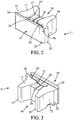
Figs. 2 and 3 are perspective views of a facing element used to build the front wall of such a structure, from its front and rear sides, respectively; -
Fig. 4 is a perspective view similar to that ofFig. 3 with a reinforcement member disposed on the facing element; -
Fig. 5 is a perspective view of a protective clip used in the embodiment ofFig. 4 ; and -
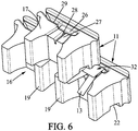
Fig. 6 is a perspective view of an assembly of a few facing elements of the front wall. - The construction work shown by way of illustration in
Fig. 1 is a mechanically stabilized soil structure. It includes afront wall 10 made of prefabricated facingelements 11 of the kind shown inFigs. 2-3 . - The
front wall 10 retainssoil material 12 of a backfill stabilized byreinforcement members 13. For example, thereinforcement members 13 may consist of flexible synthetic strips based on polyester fibers encased in polyethylene. Other types of reinforcement members are also usable as alternatives in the context of the technology described herein. Thereinforcement members 13 extend in thesoil material 12, and they are connected to thefront wall 10. - A facing
element 11 is made of a body of molded material. Itsfront side 15 is exposed to the outside of the stabilized soil structure. Itsrear side 16 retains thesoil material 12 of the structure. - In the non-limiting embodiment shown in
Figs. 1-3 , the facingelement 11 has a rectangular shape on itsfront side 15, and the rectangular facingelements 11 are assembled in horizontal rows. Two vertically adjacent rows are staggered such that each facingelement 11 covers and/or is covered by two facingelements 11 of an adjacent row. The way of assembling rectangular facingelements 11 can be different. Furthermore, it will be appreciated that paving patterns other than rectangular can be used to assemble facingelements 11 on thefront wall 10 of the stabilized soil structure. Examples include paving patterns made from hexagonal, octagonal, cross-shaped facing elements, etc. The facingelements 11 making up thefront wall 10 may all have the same shape (like inFig. 1 ), or they make a plurality of different shapes to be assembled together. - Each facing
element 11 has anupper face 17 and a lower face which are disposed horizontally when the front wall is assembled. The rows of facingelements 11 are stacked such that theupper faces 17 of the facingelements 11 of one row are in contact with the lower faces of the facingelements 11 of the overhanging row to support the weight of that overhanging row. - In the example shown in the drawings, the
rear side 16 of the facingelement 11 has an arch shape, with twovertical ribs 19 designed to project into the backfill. - On the
front side 15, the facingelement 11 may have edges configured to provide an interlocking system between adjacent facingelements 11, both vertically and horizontally. - More particularly, a lateral side of the body of molded material, namely the right side (seen from the front of the facing element 11) in the example shown, has a
protrusion 20 for contacting the left side of the adjacent facingelement 11 of the same row. Theprotrusion 20 extends between theupper face 17 and the lower face of the body. In the example shown in the drawings, theprotrusion 20 cooperates with adepression 21 having a matched shape and formed on the left side of the adjacent rectangular facingelement 11 between theupper face 17 and the lower face of the body. - At the interface between two horizontal rows, the upper and lower edges of the facing
elements 11 may also have interlocking shapes. In particular, the upper edge of thefront side 15 of the concrete body may have anextension 24 protruding above theupper face 17 of the body for cooperating withindentations 25 formed at the lower edge of the two facingelements 11 of thefront wall 10 covering theupper face 17 of the body. - The
upper face 17 of the body comprises arecess 26. In the example shown, therecess 26 is located in a front portion of theupper face 17, behind theextension 24 of thefront side 15, and it is essentially centered in relation to theribs 19. Therecess 26 may have an elongate shape parallel to thefront side 15. Therecess 26 extends horizontally over a shorter width than the width of thefront side 15. In particular, the width and the depth ofsuch recess 26 are adapted for connecting thereinforcement members 13. - The
upper face 17 of the body may further include anotch 27 that extends horizontally between therecess 26 and therear side 16. In the example shown in the drawings, thenotch 27 has a substantially isosceles trapezoid shape, seen from above, in which the short base is in contact with therecess 26. Advantageously, therecess 26 is longer than the short base of the trapezoid-shapednotch 27. In addition, thenotch 27 is formed to be less deep than therecess 26. - As shown in
Figs. 4 and6 , thenotch 27 is provided to accommodate areinforcement member 13 connected to the facingelement 11 when the front wall of the stabilized soil structure is assembled. - A bottom surface of the
notch 27 is provided with afirst drain groove 28 that extends from therear side 16 of the body to therecess 26.Such drain groove 28 splits thenotch 27 in two halves. In particular, thefirst drain groove 28 may present a downward slope from therear side 16 to therecess 26 of the body. The depth of thefirst drain groove 28 is determined in such a manner that every point of a bottom surface of thedrain groove 28 is at an equal or higher vertical position than a bottom surface of therecess 26. In the example shown in the drawings, thefirst drain groove 28 is formed at a centered position in the bottom surface of thenotch 27. - The
upper face 17 of the body is further provided with asecond drain groove 29 that extends from an end of therecess 26 to a lateral side of the body. More particularly, thesecond drain groove 29 may present a downward slope from therecess 26 to aportion 30 of the right side of the body. The depth of thesecond drain groove 29 is determined in such a manner that every point of a bottom surface of thedrain groove 29 is at an equal or lower vertical position than the bottom surface of therecess 26. Preferably, theportion 30 of right side of the body where thegroove 29 ends is located in front of theprotrusion 20. - A facing
element 11 as described above with reference toFigs. 2-3 may be manufactured using conventional molding techniques. The molded material may be concrete, without limitation. Rebars or some other kind of armatures may be embedded in the body of molded material. Special shapes such ascavities 22 may be provided, for example on the lateral sides of the body near its lower face, to facilitate handling of theelement 11 at the factory, during transportation and on-site. - In the present embodiment, the
reinforcement members 13 are connected to thefront wall 10 by means of therecess 26. As illustrated onFig. 4 , areinforcement member 13 is received by therecess 26 and thenotch 27 of the facingelement 11. In the example, each facingelement 11 receives asingle reinforcement member 13. However, there can be more than one reinforcement member per facing element. It is also possible that some of the facingelements 11 assembled to form the front wall of the structure have no reinforcement member attached thereto. - Each
reinforcement member 13 is embedded in thesoil material 12. In particular, thereinforcement member 13 is connected to the front wall when theupper face 17 of the body is covered by at least one other facingelement 11 of thefront wall 10. Thereinforcement member 13 is disposed transversely to thefront side 15 of the facingelement 11. - The
reinforcement member 13 may be connected to therecess 26 by means of an anchoringrod 31. In the example shown in the drawings, the anchoringrod 31 has a cylindrical shape whose dimensions are adjusted to fit in therecess 26. Advantageously, the length of the anchoringrod 31 is slightly less than the width of therecess 26, whereas the diameter of the anchoringrod 31 is slightly less than the depth of therecess 26. The anchoringrod 31 may be longer than the short base of the trapezoid-shapednotch 27 to provide a more robust connection of thereinforcement member 13 to thefront wall 10. - The strip-shaped
reinforcement member 13 is typically several meters in length. A first section of thereinforcement member 13 extends from thesoil material 12 to therecess 26. Insuch recess 26, thereinforcement member 13 forms a loop around the anchoringrod 31. A second section of thereinforcement member 13 extends from therecess 26 back to thesoil material 12. The first and second sections may be laid horizontally on the soil material with an angle between them. - The width of the strip-shaped
reinforcement member 13 is smaller than the short base of the trapezoid-shapednotch 27. - A
protective clip 32 is arranged around the loop formed by the strip-shapedreinforcement member 13 around the anchoringrod 31. As shown onFig. 5 , theprotective clip 32 may comprise a firstplanar portion 33 and a secondplanar portion 34. The firstplanar portion 33 is disposed substantially horizontally above the first and the second sections of the strip-shapedreinforcement member 13, and below the facing element(s) 11 of the overhanging row. The secondplanar portion 34 is disposed substantially horizontally below the first and the second sections of the strip-shapedreinforcement member 13, at the bottom of thenotch 27 formed in theupper face 17 of the facingelement 11. Both the first and the secondplanar portions reinforcement member 13, are accommodated in thenotch 27. - The
protective clip 32 may further comprise aloop portion 35 that connects the first and secondplanar portions loop portion 35 surrounds the looped part of the strip-shapedreinforcement member 13 disposed around the anchoringrod 31. Advantageously, the value of the diameter of theloop portion 35 is less than or equal to the depth of therecess 26, and greater than or equal to the diameter of the assembly formed by the anchoringrod 31 and the looped part of thereinforcement member 13. -
Fig. 6 represents a non-limiting way of assembling the facingelements 11 that constitute thefront wall 10. Proper positioning of the facingelements 11 is facilitated by the interlocking shapes provided on the vertical and horizontal edges of theirfront sides 15. - In relation to vertically adjacent rows, the facing
elements 11 of a row are laterally shifted by a distance of half of the width of thefront side 15. Eachreinforcement member 13 is then covered by two facingelements 11 of the overhanging row. Other geometrical arrangements of the facing elements are, of course, possible. - After a first row is installed,
soil material 12 can be poured behind it and compacted. Then some of thereinforcement members 13 are put in place by laying them on thesoil material 12 and disposing them around anchoringrods 31, withprotective clips 32, inrecesses 26 formed in the upper faces 17 of part or all of the facingelements 11 of the first row. Thereinforcement members 13 may be laid on the soil material according to a zigzag pattern. The second row can then be installed, the lower faces of its facingelements 11 closing therecesses 26 of the first row to complete the anchoring of thereinforcement members 13. Thennew soil material 12 is brought and the process is repeated until the prescribed height of the stabilized soil structure is reached. - It will be appreciated the assembly of the front wall and the connection of the
reinforcement members 13 thereto, as mentioned above, does not require metallic part that may become corroded. - The arrangement of the
drain grooves elements 11 allows of water that may accumulate in thesoil material 12 to be evacuated. Water present in the backfill may migrate along thereinforcement members 13. Thus, it reaches thefront wall 10 at the places where thedrain grooves 28 are positioned, and it can be evacuated to the outside via thedrain grooves 29. - It will be appreciated that the embodiments described above are illustrative of the invention disclosed herein and that various modifications can be made without departing from the scope as defined in the appended claims.
Claims (14)
- A facing element for a front wall (10) of a stabilized soil structure,
the facing element (11) comprising a body of molded material having a front side (15) to be exposed to the outside of the stabilized soil structure and a rear side (16) to retain soil material (12),
wherein an upper face (17) of the body comprises a recess (26) for connecting a reinforcement member (13) extending in the soil material (12) when the upper face (17) of the body is covered by at least one other facing element (11) of the front wall (10),
wherein the upper face (17) of the body further comprises a first drain groove (28) extending from the rear side (16) of the body to the recess (26) and a second drain groove (29) extending from an end of the recess (26) to a lateral side of the body. - A facing element as claimed in claim 1, wherein the lateral side of the body has a protrusion (20) extending between the upper face (17) and a lower face of the body for cooperating with a lateral side of at least one adjacent facing element (11) of the front wall (10), and wherein the second drain groove (29) extends from the end of the recess (26) to a portion (30) of the lateral side of the body located in front of the protrusion (20).
- A facing element as claimed in any one of the preceding claims, wherein the second drain groove (29) has a downward slope from the end of the recess (26) to the lateral side of the body.
- A facing element as claimed in any one of the preceding claims, wherein the upper face (17) of the body further comprises a notch (27) between the recess (26) and the rear side (16) for receiving the reinforcement member (13), and wherein the first drain groove (28) is formed at a bottom surface of the notch (27).
- A facing element as claimed in any claim 4, wherein the recess (26) is deeper and wider than the notch (27).
- A facing element as claimed in any one of the preceding claims, wherein the first drain groove (28) has a downward slope from the rear side (16) of the body to the recess (26).
- A facing element as claimed in any one of the preceding claims, wherein the recess (26) extends horizontally and is configured to receive an anchoring rod (31) with a loop of the reinforcement member (13) formed around the anchoring rod (31).
- A facing element as claimed in any one of the preceding claims, wherein an upper edge of the front side (15) of the body has an extension (24) protruding above the upper face (17) of the body for cooperating with an indentation (25) formed at a lower edge of the at least one other facing element (11) of the front wall (10) covering the upper face (17).
- A stabilized soil structure, comprising:a front wall (10);soil material (12) behind the front wall (10); andreinforcement members (13) extending in the soil material (12) and connected to the front wall (10),wherein the front wall (10) includes assembled facing elements (11) each comprising a body of molded material having a front side (15) to be exposed to the outside of the stabilized soil structure and a rear side (16) to retain the soil material (12),wherein the body of at least one of the facing elements (11) has an upper face (17) comprising a recess (26) for connecting one of the reinforcement members (13) when the upper face (17) is covered by at least one other assembled facing element (11) of the front wall (10),wherein the upper face (17) of the body of the at least one of the facing elements (11) further comprises a first drain groove (28) extending from the rear side (16) of the body to the recess (26) and a second drain groove (29) extending from an end of the recess (26) to a lateral side of the body.
- A stabilized soil structure as claimed in claim 9, wherein the reinforcement member (13) connected to the front wall (10) by means of the recess (26) of the upper face (17) of the at least one of the facing elements (11) is strip-shaped and connected to the front wall (10) by forming a loop around an anchoring rod (31) received in the recess (26).
- A stabilized soil structure as claimed in claim 10, further comprising a protective clip (32) mounted on the loop formed by the strip-shaped reinforcement member (13) around the anchoring rod (31) and received in the recess (26).
- A stabilized soil structure as claimed in claim 11, wherein the protective clip (32) includes:first and second planar portions (33, 34) respectively disposed above and below two sections of the strip-shaped reinforcement member (13) in a notch (27) formed in the upper face (17) between the recess (26) and the rear side (16) of the body of the at least one of the facing elements (11); anda loop portion (35) between the first and second planar portions (33, 34) for housing the anchoring rod (31) and the looped part of the strip-shaped reinforcement member (13).
- A stabilized soil structure as claimed in claim 12, wherein the first drain groove (28) is formed at a bottom surface of the notch (27) under the second planar portion (34) of the protective clip (32).
- A stabilized soil structure as claimed in any one of claims 9 to 13, wherein the first drain groove (28) has a downward slope from the rear side (16) of the body to the recess (26), and the second drain groove (29) has a downward slope from the end of the recess (26) to the lateral side of the body.
Priority Applications (1)
| Application Number | Priority Date | Filing Date | Title |
|---|---|---|---|
| EP19306084.5A EP3792405A1 (en) | 2019-09-10 | 2019-09-10 | Facing element for a front wall of a stabilized soil structure, and stabilized soil structure built with such facing elements |
Applications Claiming Priority (1)
| Application Number | Priority Date | Filing Date | Title |
|---|---|---|---|
| EP19306084.5A EP3792405A1 (en) | 2019-09-10 | 2019-09-10 | Facing element for a front wall of a stabilized soil structure, and stabilized soil structure built with such facing elements |
Publications (1)
| Publication Number | Publication Date |
|---|---|
| EP3792405A1 true EP3792405A1 (en) | 2021-03-17 |
Family
ID=68062874
Family Applications (1)
| Application Number | Title | Priority Date | Filing Date |
|---|---|---|---|
| EP19306084.5A Withdrawn EP3792405A1 (en) | 2019-09-10 | 2019-09-10 | Facing element for a front wall of a stabilized soil structure, and stabilized soil structure built with such facing elements |
Country Status (1)
| Country | Link |
|---|---|
| EP (1) | EP3792405A1 (en) |
Citations (4)
| Publication number | Priority date | Publication date | Assignee | Title |
|---|---|---|---|---|
| US5484235A (en) * | 1994-06-02 | 1996-01-16 | Hilfiker; William K. | Retaining wall system |
| US5487623A (en) * | 1993-03-31 | 1996-01-30 | Societe Civile Des Brevets Henri C. Vidal | Modular block retaining wall construction and components |
| KR20070102775A (en) * | 2006-04-17 | 2007-10-22 | 정재영 | Construction method of block type reinforced earth retaining wall |
| KR101374053B1 (en) * | 2013-09-23 | 2014-03-12 | (주)그린코리아 | A block for constructing reinforced earth wall |
-
2019
- 2019-09-10 EP EP19306084.5A patent/EP3792405A1/en not_active Withdrawn
Patent Citations (4)
| Publication number | Priority date | Publication date | Assignee | Title |
|---|---|---|---|---|
| US5487623A (en) * | 1993-03-31 | 1996-01-30 | Societe Civile Des Brevets Henri C. Vidal | Modular block retaining wall construction and components |
| US5484235A (en) * | 1994-06-02 | 1996-01-16 | Hilfiker; William K. | Retaining wall system |
| KR20070102775A (en) * | 2006-04-17 | 2007-10-22 | 정재영 | Construction method of block type reinforced earth retaining wall |
| KR101374053B1 (en) * | 2013-09-23 | 2014-03-12 | (주)그린코리아 | A block for constructing reinforced earth wall |
Similar Documents
| Publication | Publication Date | Title |
|---|---|---|
| US5607262A (en) | Retaining wall block for use with geogrids | |
| KR100981258B1 (en) | The retaining wall block and the construction method of retaining wall with retaining wall block and geogrid | |
| CN101400861B (en) | Stabilized soil structure and facing elements for its construction | |
| KR101501930B1 (en) | Retaining wall block and the construction method | |
| US20050069389A1 (en) | Interlocking and securable retaining wall block and system | |
| AU2003210567A1 (en) | Interlocking and securable retaining wall block and system | |
| KR20140047924A (en) | Construction method of cast-in-place step retaining wall using pc panel needless of concrete forms for slope reinforcement | |
| US7544014B1 (en) | Retaining wall anchor system | |
| RU194151U1 (en) | ARMOGROUND SUPPORT WALL FROM FACING BLOCKS | |
| JP7715383B2 (en) | Slope crushed stone laying structure and slope protection structure | |
| RU2330142C1 (en) | Facing block-anchor for mortarless brickwork of back wall and back wall | |
| KR102448199B1 (en) | Prefabricated Composite Block | |
| JPH0739700B2 (en) | Insulated wall structure | |
| KR101437845B1 (en) | Fabricated trench | |
| RU224782U1 (en) | Modular retaining wall block | |
| KR20130001219U (en) | Drainage panel | |
| CA2816186A1 (en) | Retaining wall system | |
| JP4194185B2 (en) | Seawall block | |
| KR200404658Y1 (en) | Prefabricated Buttressed Retaining Wall | |
| KR101724077B1 (en) | Reinforced retaining wall | |
| KR100647071B1 (en) | Retaining Wall Block Construction Method | |
| EP1726721A1 (en) | A system for anchoring a wall structure of concrete blocks | |
| KR102592440B1 (en) | Insert typed Load-Bearing Insulation for preventing thermal bridge at junctions between parapet and roof slab, and construction method using thereof | |
| KR100940339B1 (en) | Reinforced retainaing wall easily constructed and constructing method thereof | |
| KR20120051299A (en) | Drainage panel |
Legal Events
| Date | Code | Title | Description |
|---|---|---|---|
| PUAI | Public reference made under article 153(3) epc to a published international application that has entered the european phase |
Free format text: ORIGINAL CODE: 0009012 |
|
| STAA | Information on the status of an ep patent application or granted ep patent |
Free format text: STATUS: THE APPLICATION HAS BEEN PUBLISHED |
|
| AK | Designated contracting states |
Kind code of ref document: A1 Designated state(s): AL AT BE BG CH CY CZ DE DK EE ES FI FR GB GR HR HU IE IS IT LI LT LU LV MC MK MT NL NO PL PT RO RS SE SI SK SM TR |
|
| AX | Request for extension of the european patent |
Extension state: BA ME |
|
| STAA | Information on the status of an ep patent application or granted ep patent |
Free format text: STATUS: THE APPLICATION IS DEEMED TO BE WITHDRAWN |
|
| 18D | Application deemed to be withdrawn |
Effective date: 20210918 |