EP3791938B1 - Mobile weight training system - Google Patents
Mobile weight training system Download PDFInfo
- Publication number
- EP3791938B1 EP3791938B1 EP20204244.6A EP20204244A EP3791938B1 EP 3791938 B1 EP3791938 B1 EP 3791938B1 EP 20204244 A EP20204244 A EP 20204244A EP 3791938 B1 EP3791938 B1 EP 3791938B1
- Authority
- EP
- European Patent Office
- Prior art keywords
- end portion
- barbell
- collar
- sleeve
- weight
- Prior art date
- Legal status (The legal status is an assumption and is not a legal conclusion. Google has not performed a legal analysis and makes no representation as to the accuracy of the status listed.)
- Active
Links
Images


Classifications
-
- A—HUMAN NECESSITIES
- A63—SPORTS; GAMES; AMUSEMENTS
- A63B—APPARATUS FOR PHYSICAL TRAINING, GYMNASTICS, SWIMMING, CLIMBING, OR FENCING; BALL GAMES; TRAINING EQUIPMENT
- A63B21/00—Exercising apparatus for developing or strengthening the muscles or joints of the body by working against a counterforce, with or without measuring devices
- A63B21/06—User-manipulated weights
- A63B21/072—Dumb-bells, bar-bells or the like, e.g. weight discs having an integral peripheral handle
- A63B21/075—Dumb-bells, bar-bells or the like, e.g. weight discs having an integral peripheral handle with variable weights, e.g. weight systems with weight selecting means for bar-bells or dumb-bells
-
- A—HUMAN NECESSITIES
- A63—SPORTS; GAMES; AMUSEMENTS
- A63B—APPARATUS FOR PHYSICAL TRAINING, GYMNASTICS, SWIMMING, CLIMBING, OR FENCING; BALL GAMES; TRAINING EQUIPMENT
- A63B21/00—Exercising apparatus for developing or strengthening the muscles or joints of the body by working against a counterforce, with or without measuring devices
- A63B21/06—User-manipulated weights
- A63B21/0601—Special physical structures of used masses
- A63B21/0602—Fluids, e.g. water
-
- A—HUMAN NECESSITIES
- A63—SPORTS; GAMES; AMUSEMENTS
- A63B—APPARATUS FOR PHYSICAL TRAINING, GYMNASTICS, SWIMMING, CLIMBING, OR FENCING; BALL GAMES; TRAINING EQUIPMENT
- A63B21/00—Exercising apparatus for developing or strengthening the muscles or joints of the body by working against a counterforce, with or without measuring devices
- A63B21/06—User-manipulated weights
- A63B21/0601—Special physical structures of used masses
- A63B21/0603—Fluid-like particles, e.g. gun shot or sand
-
- A—HUMAN NECESSITIES
- A63—SPORTS; GAMES; AMUSEMENTS
- A63B—APPARATUS FOR PHYSICAL TRAINING, GYMNASTICS, SWIMMING, CLIMBING, OR FENCING; BALL GAMES; TRAINING EQUIPMENT
- A63B21/00—Exercising apparatus for developing or strengthening the muscles or joints of the body by working against a counterforce, with or without measuring devices
- A63B21/06—User-manipulated weights
- A63B21/072—Dumb-bells, bar-bells or the like, e.g. weight discs having an integral peripheral handle
- A63B21/0722—Dumb-bells, bar-bells or the like, e.g. weight discs having an integral peripheral handle transformable, e.g. from dumb-bell to bar-bell
-
- A—HUMAN NECESSITIES
- A63—SPORTS; GAMES; AMUSEMENTS
- A63B—APPARATUS FOR PHYSICAL TRAINING, GYMNASTICS, SWIMMING, CLIMBING, OR FENCING; BALL GAMES; TRAINING EQUIPMENT
- A63B21/00—Exercising apparatus for developing or strengthening the muscles or joints of the body by working against a counterforce, with or without measuring devices
- A63B21/06—User-manipulated weights
- A63B21/072—Dumb-bells, bar-bells or the like, e.g. weight discs having an integral peripheral handle
- A63B21/0724—Bar-bells; Hand bars
-
- A—HUMAN NECESSITIES
- A63—SPORTS; GAMES; AMUSEMENTS
- A63B—APPARATUS FOR PHYSICAL TRAINING, GYMNASTICS, SWIMMING, CLIMBING, OR FENCING; BALL GAMES; TRAINING EQUIPMENT
- A63B21/00—Exercising apparatus for developing or strengthening the muscles or joints of the body by working against a counterforce, with or without measuring devices
- A63B21/40—Interfaces with the user related to strength training; Details thereof
- A63B21/4041—Interfaces with the user related to strength training; Details thereof characterised by the movements of the interface
- A63B21/4049—Rotational movement
-
- A—HUMAN NECESSITIES
- A63—SPORTS; GAMES; AMUSEMENTS
- A63B—APPARATUS FOR PHYSICAL TRAINING, GYMNASTICS, SWIMMING, CLIMBING, OR FENCING; BALL GAMES; TRAINING EQUIPMENT
- A63B71/00—Games or sports accessories not covered in groups A63B1/00 - A63B69/00
- A63B71/0036—Accessories for stowing, putting away or transporting exercise apparatus or sports equipment
-
- A—HUMAN NECESSITIES
- A63—SPORTS; GAMES; AMUSEMENTS
- A63B—APPARATUS FOR PHYSICAL TRAINING, GYMNASTICS, SWIMMING, CLIMBING, OR FENCING; BALL GAMES; TRAINING EQUIPMENT
- A63B71/00—Games or sports accessories not covered in groups A63B1/00 - A63B69/00
- A63B71/06—Indicating or scoring devices for games or players, or for other sports activities
- A63B71/0619—Displays, user interfaces and indicating devices, specially adapted for sport equipment, e.g. display mounted on treadmills
- A63B2071/065—Visualisation of specific exercise parameters
-
- A—HUMAN NECESSITIES
- A63—SPORTS; GAMES; AMUSEMENTS
- A63B—APPARATUS FOR PHYSICAL TRAINING, GYMNASTICS, SWIMMING, CLIMBING, OR FENCING; BALL GAMES; TRAINING EQUIPMENT
- A63B71/00—Games or sports accessories not covered in groups A63B1/00 - A63B69/00
- A63B71/06—Indicating or scoring devices for games or players, or for other sports activities
- A63B71/0619—Displays, user interfaces and indicating devices, specially adapted for sport equipment, e.g. display mounted on treadmills
- A63B2071/0658—Position or arrangement of display
-
- A—HUMAN NECESSITIES
- A63—SPORTS; GAMES; AMUSEMENTS
- A63B—APPARATUS FOR PHYSICAL TRAINING, GYMNASTICS, SWIMMING, CLIMBING, OR FENCING; BALL GAMES; TRAINING EQUIPMENT
- A63B71/00—Games or sports accessories not covered in groups A63B1/00 - A63B69/00
- A63B71/06—Indicating or scoring devices for games or players, or for other sports activities
- A63B2071/0675—Input for modifying training controls during workout
- A63B2071/0683—Input by handheld remote control
-
- A—HUMAN NECESSITIES
- A63—SPORTS; GAMES; AMUSEMENTS
- A63B—APPARATUS FOR PHYSICAL TRAINING, GYMNASTICS, SWIMMING, CLIMBING, OR FENCING; BALL GAMES; TRAINING EQUIPMENT
- A63B71/00—Games or sports accessories not covered in groups A63B1/00 - A63B69/00
- A63B71/06—Indicating or scoring devices for games or players, or for other sports activities
- A63B2071/0694—Visual indication, e.g. Indicia
-
- A—HUMAN NECESSITIES
- A63—SPORTS; GAMES; AMUSEMENTS
- A63B—APPARATUS FOR PHYSICAL TRAINING, GYMNASTICS, SWIMMING, CLIMBING, OR FENCING; BALL GAMES; TRAINING EQUIPMENT
- A63B21/00—Exercising apparatus for developing or strengthening the muscles or joints of the body by working against a counterforce, with or without measuring devices
- A63B21/06—User-manipulated weights
- A63B21/072—Dumb-bells, bar-bells or the like, e.g. weight discs having an integral peripheral handle
- A63B21/0728—Dumb-bells, bar-bells or the like, e.g. weight discs having an integral peripheral handle with means for fixing weights on bars, i.e. fixing olympic discs or bumper plates on bar-bells or dumb-bells
-
- A—HUMAN NECESSITIES
- A63—SPORTS; GAMES; AMUSEMENTS
- A63B—APPARATUS FOR PHYSICAL TRAINING, GYMNASTICS, SWIMMING, CLIMBING, OR FENCING; BALL GAMES; TRAINING EQUIPMENT
- A63B2209/00—Characteristics of used materials
- A63B2209/10—Characteristics of used materials with adhesive type surfaces, i.e. hook and loop-type fastener
-
- A—HUMAN NECESSITIES
- A63—SPORTS; GAMES; AMUSEMENTS
- A63B—APPARATUS FOR PHYSICAL TRAINING, GYMNASTICS, SWIMMING, CLIMBING, OR FENCING; BALL GAMES; TRAINING EQUIPMENT
- A63B2210/00—Space saving
- A63B2210/50—Size reducing arrangements for stowing or transport
-
- A—HUMAN NECESSITIES
- A63—SPORTS; GAMES; AMUSEMENTS
- A63B—APPARATUS FOR PHYSICAL TRAINING, GYMNASTICS, SWIMMING, CLIMBING, OR FENCING; BALL GAMES; TRAINING EQUIPMENT
- A63B2220/00—Measuring of physical parameters relating to sporting activity
- A63B2220/50—Force related parameters
- A63B2220/51—Force
-
- A—HUMAN NECESSITIES
- A63—SPORTS; GAMES; AMUSEMENTS
- A63B—APPARATUS FOR PHYSICAL TRAINING, GYMNASTICS, SWIMMING, CLIMBING, OR FENCING; BALL GAMES; TRAINING EQUIPMENT
- A63B2220/00—Measuring of physical parameters relating to sporting activity
- A63B2220/50—Force related parameters
- A63B2220/51—Force
- A63B2220/52—Weight, e.g. weight distribution
-
- A—HUMAN NECESSITIES
- A63—SPORTS; GAMES; AMUSEMENTS
- A63B—APPARATUS FOR PHYSICAL TRAINING, GYMNASTICS, SWIMMING, CLIMBING, OR FENCING; BALL GAMES; TRAINING EQUIPMENT
- A63B2220/00—Measuring of physical parameters relating to sporting activity
- A63B2220/50—Force related parameters
- A63B2220/56—Pressure
-
- A—HUMAN NECESSITIES
- A63—SPORTS; GAMES; AMUSEMENTS
- A63B—APPARATUS FOR PHYSICAL TRAINING, GYMNASTICS, SWIMMING, CLIMBING, OR FENCING; BALL GAMES; TRAINING EQUIPMENT
- A63B71/00—Games or sports accessories not covered in groups A63B1/00 - A63B69/00
- A63B71/06—Indicating or scoring devices for games or players, or for other sports activities
- A63B71/0619—Displays, user interfaces and indicating devices, specially adapted for sport equipment, e.g. display mounted on treadmills
- A63B71/0622—Visual, audio or audio-visual systems for entertaining, instructing or motivating the user
Definitions
- US 5,997,442 A describes a portable, multi-purpose exercise system that includes dumbbell bars configured for interconnection to form a barbell and a plurality of hollow, rigid discs configured for attachment to the dumbbell bars. The discs are fillable with water to provide a consistent and accurate amount of weight.
- the discs and dumbbell bars are stored within a portable transport and storage case that may be used as a bench for weightlifting exercises and a bench step for aerobic exercise.
- a headrest is included that is attachable to the storage case and extension blocks are provided for adjusting the height of the storage case when used for exercise.
- the extension blocks also provide extra storage space for other items, along with a separate storage compartment that is configured for storing the headrest when not in use.
- three dumbbell bars are interconnected to form a barbell bar.
- Weight discs include a through-hole that is used to engage a dumbbell bar.
- This specification relates to a barbell.
- a mobile weight training system can include a mobile barbell, several weight holders, and a system of filler bags.
- the filler bags can be filled with various readily available materials (e.g., sand, dirt, water, gravel, etc.) and inserted into the weight holders to create weights for use with the barbell.
- the system of filler bags can include several filler bags of different sizes, each size designed to hold an approximate weight of a material.
- such a mobile weight training system can include enough weight holders and filler bags to produce 270 pounds of weight when filled, but with a travel weight (e.g., weight of the system with empty filler bags) not much greater that the weight of the barbell alone. Consequently, the weight training system may be adaptable to a user's needs while minimizing the storage weight and size of the system.
- a first general aspect of the subject matter described in this specification can be embodied in a barbell including a first end portion, a second end portion, and a middle portion, where the middle portion is couplable to the first end portion and the second end portion along only a portion of a length of the corresponding male coupling.
- the first and second coupling mechanisms can include plunger buttons and corresponding holes.
- the first and second coupling mechanisms can include pins.
- the first and second coupling mechanisms can include locking sleeves.
- the female coupling of the first end portion and the male coupling of the second end portion can be corresponding couplings so as to couple the first end portion with the second end portion without the middle portion.
- the first end portion can be configured to hold a weight at an end of the first end portion opposite the female coupling on the first end portion
- the second end portion can be configured to hold a weight at an end of the second end portion opposite the male coupling on the second end portion.
- the barbell can include a first cylindrical collar coaxially attached to the first end portion, the first collar having a channel formed around an outer circumference of the collar, and a second a second cylindrical collar coaxially attached to the second end portion, the second collar having a channel formed around an outer circumference of the collar.
- a weight sensing device can be mounted on one of the first end portion or the second end portion.
- the weight sensing device can be a mechanical scale.
- the weight sensing device can be integrated into a collar attached to the first end portion or the second end portion.
- the weight sensing device can be a pressure sensor communicatively coupled to an electronic display.
- a second general aspect, combinable with the first general aspect, can be embodied in an exercise weight including a flexible weight holder having a plurality of sealable chambers, the chambers arranged along a length of the weight holder and oriented transverse to the length of the weight holder, and each chamber having a closure device for securing one or more weights within each chamber.
- One or more straps attached to a first end of the weight holder, the first end being transverse to the length of the weight holder.
- one or more strap fastening devices attached at a second end of the weight holder, the second end being transverse to the length of the weight holder, where the weight holder is rolled into a cylinder shape when each of the straps are fastened to corresponding ones of the strap fastening devices.
- the strap fastening devices can be hook and loop fasteners, where the straps include one of the hooks or the loops of the hook and loop fasteners and the other of the hooks of the loops of the hook and loop fasteners are attached to a surface of the weight holder at the second end.
- the strap fastening devices can include one of double D-rings, buckles, clips, or snaps. At least one handle can be attached to a surface of the weight holder.
- the weight holder when rolled into the cylinder shape, can define an passage running transverse to the length of the weight holder, such that the weight holder can be wrapped around an end of a barbell.
- a third general aspect, combinable with any of the previous aspects, can be embodied in a weight training system including a barbell and two or more exercise weights.
- the barbell including a first end portion, a second end portion, and a middle portion couplable to the first end portion and the second end portion.
- the middle portion having a male coupling extending from a first end of the middle portion, the male coupling providing a first coupling mechanism that engages with a corresponding female coupling of the first end portion, and a female coupling providing a second coupling mechanism that engages with a corresponding male coupling of the second end portion.
- Each of the two or more exercise weights including a flexible weight holder having a plurality of chambers, the chambers arranged along a length of the weight holder and oriented transverse to the length of the weight holder, and each chamber having a closure device for securing one or more weights within each chamber, one or more straps attached to a first end of the weight holder, the first end being transverse to the length of the weight holder, and one or more strap fastening devices attached at a second end of the weight holder, the second end being transverse to the length of the weight holder, wherein the weight holder is rolled into a cylinder shape when each of the straps are fastened to corresponding ones of the strap fastening devices.
- a plurality of filler bags each filler bag being sized to accommodate an amount of a material that approximates a weight of each filler bag, and each filler bag fitting within the chambers of the weight holders.
- the material can be one of water, sand, dirt, or gravel.
- a fourth general aspect, combinable with any of the previous aspects, can be embodied in a method of assembling a weight training system including the steps of assembling a barbell by: coupling a male coupling of a first end portion to a female coupling of a middle portion, and coupling a male coupling of the middle portion to a female coupling of a second end portion.
- Assembling a first weight for the barbell by: adding a material to a filler bag and sealing the filler bag, inserting the filler bag in a chamber of a first weight holder, and sealing the chamber of the weight holder. And, attaching the first weight to the barbell by wrapping the first weight holder around the first end portion or the second end portion, and securing straps on the first weight holder to corresponding strap fasteners on the first weight holder.
- Assembling a second weight for the barbell by: adding a material to a second filler bag and sealing the second filler bag, inserting the second filler bag in a chamber of a second weight holder, and sealing the chamber of the second weight holder. Attaching the second weight to the barbell by placing a handle of a second weight holder into a channel of a collar on the first end portion or the second end portion of the barbell. Attaching the second weight to the barbell by wrapping the second weight holder around the first weight, and securing straps on the second weight holder to corresponding strap fasteners on the second weight holder.
- Implementations may provide a compact and light-weight weight training system. Implementations may be adaptable to different training styles. Further, implementations may permit use with both conventional plate weights and non-conventional weights with a barbell.
- FIG. 1 depicts an example mobile weight training system 100 in accordance with implementations of the present disclosure.
- the system 100 includes a collapsible barbell 102, a set of weight holders 104, a system of filler bags 106, and a case 108 that can double as a weight-bench.
- the filler bags 106 can be filled with various readily available materials such as, but not limited to, sand, dirt, water, or gravel, and attached to the weight holders 104 to create weights for use with the barbell.
- the weight holders 104 can be attached to the barbell 102 by wrapping the weight holders 104 around the ends of the barbell 102 or, in some examples, by hanging the weight holders 104 from the barbell using a handle on the weight holder 104 (e.g., as shown in FIGs. 2D and 9C ).
- the system of filler bags 106 can include several filler bags 106 of different sizes, each size designed to hold an approximate weight of material (e.g., 5, 10, and 15 pounds, wherein 1 Pound corresponds to 0,45kg).
- a mobile weight training system 100 can include enough weight holders 104 and filler bags 106 to produce 270 pounds of weight when filled (e.g., 6 weight holders, 12 - 15lb bags, 6 - 10lb bags, and 6 - 5lb bags, wherein 1 lb corresponds to 0,45kg), but with a travel weight (e.g., weight of the system with empty filler bags) not much greater that the weight of the barbell 102 alone.
- a travel weight e.g., weight of the system with empty filler bags
- FIGs. 2A-2D depict various views of an example mobile barbell 102 in accordance with implementations of the present disclosure.
- FIGs. 2A-2C show various configurations of the barbell 102
- FIG. 2D shows the barbell 102 with weight holders 104 attached.
- the barbell 102 can be broken down into three separate parts (202, 204, 206) for storage and travel.
- the parts include two end portions (female end portion 202 and male end portion 204) and a middle portion 206.
- Each end portion 202, 204 has either a male coupling 210a (male end portion 204) or a female coupling 210b (female end portion 202).
- the middle section 206 has a male coupling 210a at one end and a female coupling 210b the opposite end.
- the couplings 210a, 210b secure the end portions 202, 204 of the barbell to the middle portion 206.
- the male coupling 210a on the male end portion 204 fastens to the female coupling 210b of the middle portion 206
- the female coupling 210b of female end portion 202 fastens to the male coupling 210a of the middle portion 206.
- the couplings 210a, 210b can include any of several different coupling mechanisms (e.g., threading, pins, or plunger buttons) to fasten the parts of the barbell 102 together.
- FIGs. 3A-3C and 4A-4C depict detail and perspective views, respectively, of each of the parts (portions 202, 204, 206) of the barbell 102.
- FIGs. 3A and 4A show detail and perspective views of the female end portion 202.
- the female end portion 202 includes a collar 212 and a hollow cylindrical sleeve 214 attached coaxially to the female end portion 202. Either the collar 212, the sleeve 214, or both can be attached to the female end portion 202 such that they are free to rotate around the female end portion 202.
- the collar 212 and sleeve 214 can be mounted on bearings (e.g., brass bushings) placed between the female end portion 202, and the collar and sleeve 214.
- the collar 212 and the sleeve 214 can form a single assembly, for example, by affixing the collar 212 to the sleeve (e.g., by welding or press fitting the two together).
- the sleeve 214 and collar 212 can be formed in one piece.
- the sleeve 214 and collar 212 be machined from one piece of material.
- a seal 218 (e.g., a gasket or V-seal) can be placed between the female end portion 202 and the collar 212, and/or between the female end portion 202 and the sleeve 214 to prevent debris from fouling the bearings and impeding the rotation of the collar 212 and/or the sleeve 214.
- the V-seal is mounted axially on the bar, with a lip in contact with the bushing inside the collar/sleeve assembly to prevent debris from fouling the bushing from the interior side of the collar/sleeve assembly.
- FIGs. 3B and 4B show detail and perspective views of the male end portion 204.
- the male end portion 204 includes a collar 212 and a hollow cylindrical sleeve 214 attached coaxially to the male end portion 204.
- Either the collar 212, the sleeve 214, or both can be attached to the male end portion 204 such that they are free to rotate around the female end portion 204.
- the collar 212 and sleeve 214 can be mounted on bearings placed between male end portion 204, and the collar and sleeve 214.
- the collar 212 and the sleeve 214 can form a single assembly, for example, by affixing the collar 212 to the sleeve (e.g., by welding or press fitting the two together).
- the sleeve 214 and collar 212 can be formed in one piece.
- the sleeve 214 and collar 212 be machined from one piece of material..
- a seal 218 (e.g., a gasket or v-seal) can be placed between the male end portion 204 and the collar 212, and/or between male end portion 204 and the sleeve 214 to prevent debris from fouling the bearings and impeding the rotation of the collar 212 and/or the sleeve 214.
- the V-seal is mounted axially on the bar, with a lip in contact with the bushing inside the collar/sleeve assembly to prevent debris from fouling the bushing from the interior side of the collar/sleeve assembly.
- the weight holders 104 are attached to the sleeves 214 of the barbell 102.
- the sleeves 214 can have a diameter similar to industry standard Olympic barbell sleeves of, for example, 1 and 31/32 inches, such that the barbell 102 can be used with standard weights in addition to the weight holders 104.
- the collars 212 can serve as a hanger for additional weight holders 104 (e.g., as shown in FIG. 2D ).
- the collar 212 has a channel 216 formed in the outer surface and running along the circumference of the collar 212. The channel 216 can be sized to cradle a handle on the weight holders 104, thereby preventing a weight holder 104 hung from the barbell 102 from sliding during lifts.
- the barbell 102 when fully assembled, has standard Olympic dimensions, for example, 2.2m (7.2ft) long and weighing 20kg (44lb), however, implementations may vary in weight and length, for example, to suit differing training routines.
- the barbell 102 can be slightly longer than an Olympic barbell, for example, to accommodate the longer weight holders 104 the sleeves 214 can be extended an appropriate distance, as compared to a standard Olympic barbell.
- the two end portions 202, 204 can be fastened together without the middle portion 206 by, for example, coupling the respective male 210a and female 210b couplings of the male 204 and female 202 end portions together to form a shorter barbell 102, for example, a curl bar (as shown in FIG. 2C ).
- the barbell 102 can be made of more than three portions to, for example, make the barbell 102 even more compact for travel and storage.
- the middle portion 206 can be formed from two separate middle portions 206a, 206b. Each middle portion 206a, 206b has both male 210a and female 210b couplings. Further, the middle portions 206a, 206b can be of different lengths, for example, to permit more adaptability in barbell sizes.
- the middle portions 206a, 206b can be sized such that a woman's Olympic bar (e.g., 2.01m (6.6ft) long and weighing 15kg (33lb)) can formed using only one of the middle portions, and a men's Olympic bar can be formed using both of the middle portions.
- a woman's Olympic bar e.g., 2.01m (6.6ft) long and weighing 15kg (33lb)
- FIG. 5 depicts example threading configurations that can be used as coupling mechanisms for the male 210a and female 210b couplings.
- Threading configurations 502 and 504 show threads extending from an end of a barbell portion (e.g., portion 204, 206) along only a portion the male coupling 210a. Further, threading configuration 502 shows a finer thread pitch than that of threading configuration 504. Also, threading configurations 502 and 504 represent undercut threading configurations (e.g., a configuration in which the shank of the male coupling has a diameter equal to the pitch diameter of the threads).
- threading configurations 502 and 504 can be modified, in some examples, such that the threaded portion of the male coupling 210a is at the distal end (e.g., the end away from the barbell portion 204, 206).
- the unthreaded portion of the male coupling 210a is proximate to the barbell portion 204, 206 and the threaded portion of the male coupling 210a is at the distal end of the male portion 210a.
- Threading configuration 506 shows an example threading configuration in which the threads extend along the entire length of the male coupling 210a. Further, threading configuration 506 represents a full-bodied threading configuration (e.g., a configuration in which the shank of the male coupling has a diameter equal to the maj or diameter of the threads). Although not shown, the female couplings 210b are tapped with corresponding thread grooves.
- FIGs. 6A and 6B depict another example coupling mechanism for the male 210a and female 210b couplings.
- FIG. 6A shows a cross-sectional view of a pin and hole type of coupling mechanism 600.
- the male 210a and female coupling 210b each have corresponding holes 604 and 606, respectively, which can be aligned when the male coupling 210a is inserted into the female coupling 210b.
- the two couplings 210a, 210b are secured together by pins 602 inserted through the aligned holes 604, 606.
- the holes 604 in the male coupling 210a can be tapped to accept a spring and plunger assembly 650.
- the assembly 650 includes a threaded body 652 and a movable plunger 654 held under spring pressure by a spring (not shown) within the body 652. The plunger 654 can be moved into the body 652 against the spring pressure.
- the assembly 650 can include a thread locking element 656 (e.g., nylon, thread locking tape, or thread locking liquid).
- FIG. 7 depicts an example weight holder 104 in accordance with implementations of the present disclosure.
- a front side of the weight holder 104 is shown in FIG. 7 .
- the weight holder 104 is made of a strong but flexible material, for example, a fabric such as 1000 Denier Mil-Spec Cordura Nylon or other appropriate high strength fabric.
- the weight holder 104 has several sealable chambers 702 in which weights (e.g., filler bags 106) can be inserted.
- the chambers 702 have an opening 704 at one end, and a closure mechanism 706.
- the closure mechanism 706 can be, for example, a zipper or a flap with a fastening device such as, but not limited to, hook and loop fasteners, snaps, metal or plastic clips.
- each chamber 702 has a separate closure mechanism (e.g., a separate flap).
- the weight holder 104 has a single closure mechanism 706 (e.g., a single flap) that encloses all of the chambers 702.
- the weight holder 104 has one or more straps 708 and corresponding strap fastening devices 710.
- the straps 708 are attached to an end of the weight holder 104 that is transverse to the orientation of the chambers 702, and the strap fastening devices 710 are attached at an opposite end of the weight holder 104, also transvers to the orientation of the chambers 702.
- the straps 708 and strap fastening devices 710 are positioned on the weight holder 104 such that, when the straps 708 are secured to corresponding strap fastening devices 710, the weight holder is wrapped into a hollow cylindrical shape (e.g., see FIGs. 8B and 9C ), thereby allowing weight holders 104 to be wrapped around the sleeve 214 of a barbell 102.
- the weight holder is made to lie flat when not wrapped into the cylinder shape, for example, making the weight holder more space-efficient during storage.
- the strap fastening devices 710 can be hook or loop fasteners corresponding to respective loop or hook fasteners on the straps 708.
- the strap fastening devices 710 can be fastening devices such as, but not limited to, double D-ring loops, buckles, S-hook straps, ladder lock buckles, metal or plastic clips (e.g., corresponding clips on the straps 708), or snaps.
- the weight holder 104 has three chambers 702, and the chambers are oriented on the weight holder such that, when the weight holder 104 is rolled up and the straps 708 secured, the weight holder 104 has a triangular cross-section (e.g., as shown in FIGs. 8B and 9C ).
- design e.g., the cross section
- each chamber 702 of the weight holder 104 is sized to hold fifteen pounds of filler bags 106 (e.g., 1 - 15lb filler bag; 1 - 10lb and 1 - 5lb filler bag; or 3 - 5lb filler bags), with a total fillable weight of 45lbs.
- filler bags 106 e.g., 1 - 15lb filler bag; 1 - 10lb and 1 - 5lb filler bag; or 3 - 5lb filler bags
- the weight holder 104 includes one or more handles 712, 714.
- the handles can be, for example, fabric handles 712 (e.g., nylon webbing) or molded plastic handles 714.
- FIGs. 8A and 8B depict example filler bags 106 and an example weight holder 104 in accordance with implementations of the present disclosure.
- FIG. 8A shows a back side of the weight holder 104 and filler bags 106 being inserted into the weight holder 104.
- FIG. 8B shows an example weight holder 104 loaded with filler bags 106 and rolled up to be placed on an end of a barbell 102.
- the weight holder 104 is rolled into a cylindrical shape.
- FIG. 8A shows filler bags 106 being inserted into the chambers 702 of a weight holder 104.
- weight holder 104 When a weight holder 104 is filled with a desired weight of filler bags 106, the weight holder 104 can be rolled into the configuration shown in FIG. 8B by attaching the straps 708 to corresponding strap fastening devices 710..
- the filler bags 106 are made of a high strength flexible material such as, for example, 1000 Denier Mil-Spec Cordura Nylon.
- the filler bags 106 also have a closure mechanism 802, for example, similar to the closure mechanism 706 of the weight holder 104.
- the closure mechanism 802 can be, for example, a zipper or a flap with a fastening device such as, but not limited to, hook and loop fasteners, snaps, metal or plastic clips.
- the filler bags 106 can have a double closure mechanism 802.
- the filler bags can have two overlapping closure mechanisms 802 of the same (e.g., overlapping flaps with hook and loop fasteners) or different type (e.g., a zipper and a flap with hook and loop fasteners).
- the filler bags 106 may have a water tight liner and water tight closure 802 such that the filler bags 106 can be filled with water.
- the filler bags 106 can have a handle attached to an outer surface of the bag.
- FIGs. 9A-9C depict various methods of attaching weight bags 104 to a barbell 102 in accordance with implementations of the present disclosure.
- FIG. 9A shows one weight holder 104 attached at each end of the barbell 102.
- the weight holders 104 are wrapped around the sleeves 214 of the barbell 102.
- the straps 708 can be pulled snug and attached to the strap fastening devices 710 to securely fasten the weight holders 104 to the barbell 102.
- FIG. 9B shows a barbell 102 with four weight holders 104 attached.
- the straps of the weight holders 104 are long enough that weight holders 104 can be wrapped around each other on a barbell sleeve 214.
- the first two weight holders 104 are attached as described above in reference to FIG. 9A .
- Each of the second two weight holders 104 are then wrapped around one of the first two weight holders 104 previously attached to the barbell sleeves 214.
- FIG. 9C shows a barbell 102 with six weight holders 104 attached (e.g., a third set of two weight holders 104).
- a weight holder 104 is hung on each collar 212 of the barbell.
- the weight holders 104 can be hung on the collars 212 by placing one of the weight holder handles 712 in the channel 216 of the collar 212.
- the collar channel 216 prevents weight holders 104 hung in this fashion from sliding during lifts.
- FIG. 10 depicts an example barbell scale 1000.
- the scale 1000 may be attached to or integrated with a barbell 102.
- the scale 1000 can be attached to or integrated with the collar 212 on either the male portion 204, the female portion 202, or both.
- the scale 1000 can be a mechanical scale, as shown in FIGs. 11A and 11B .
- the scale 1000 can include a moveable element 1102 positioned in a notch 1104 of the collar 212. Springs 1106 are positioned between an inner surface of the notch 1104 and the moveable element 1102. When a weight holder 104 is hung on the collar 212 (e.g., as shown in FIG.
- the weight of the weight holder compresses the springs 1106, thereby translating the moveable element 1102 within the notch 1104.
- a tab 1108 of the moveable element 1102 extends through a side surface of the collar 212 and can serve as a pointer to a calibrated set of weight markings 1110 on the side of the collar 212.
- the scale 1000 in pressure sensing device includes an electronic pressure sensor 1002 in electronic communication with an electronic display device 1006, for example, through a detachable wire 1004.
- the electronic display device 1006 includes one or more processors and a data store storing instructions for processing electrical signals from the electronic pressure sensing device 1002 and displaying a weight.
- the display device can be a mobile computing device such as, for example, a tablet computer or a smartphone.
- an application executed by the mobile computing device can process the signals from the electronic pressure sensor and display a weight.
- the electronic pressure sensor 1102 can be integrated with a mechanical scale, such as shown in FIGs. 11A and 11B .
Landscapes
- Health & Medical Sciences (AREA)
- General Health & Medical Sciences (AREA)
- Physical Education & Sports Medicine (AREA)
- Life Sciences & Earth Sciences (AREA)
- Biophysics (AREA)
- Orthopedic Medicine & Surgery (AREA)
- Purses, Travelling Bags, Baskets, Or Suitcases (AREA)
- Instructional Devices (AREA)
- Percussion Or Vibration Massage (AREA)
- Mutual Connection Of Rods And Tubes (AREA)
Description
- Individuals involved in certain professions such as, for example, the military, law enforcement, and extreme sports, may travel to locations where traditional weight training equipment is unavailable. Yet, these professions demand that their members maintain peak fitness. Moreover, traditional weight systems are heavy and unwieldy, hence limiting the type of workout equipment or amount of weights that can be transported to such locations.
US 5,997,442 A describes a portable, multi-purpose exercise system that includes dumbbell bars configured for interconnection to form a barbell and a plurality of hollow, rigid discs configured for attachment to the dumbbell bars. The discs are fillable with water to provide a consistent and accurate amount of weight. The discs and dumbbell bars are stored within a portable transport and storage case that may be used as a bench for weightlifting exercises and a bench step for aerobic exercise. A headrest is included that is attachable to the storage case and extension blocks are provided for adjusting the height of the storage case when used for exercise. The extension blocks also provide extra storage space for other items, along with a separate storage compartment that is configured for storing the headrest when not in use. In one example, three dumbbell bars are interconnected to form a barbell bar. Weight discs include a through-hole that is used to engage a dumbbell bar. - This specification relates to a barbell.
- The invention is defined by the appended claims.
- A mobile weight training system can include a mobile barbell, several weight holders, and a system of filler bags. The filler bags can be filled with various readily available materials (e.g., sand, dirt, water, gravel, etc.) and inserted into the weight holders to create weights for use with the barbell. The system of filler bags can include several filler bags of different sizes, each size designed to hold an approximate weight of a material. For example, such a mobile weight training system can include enough weight holders and filler bags to produce 270 pounds of weight when filled, but with a travel weight (e.g., weight of the system with empty filler bags) not much greater that the weight of the barbell alone. Consequently, the weight training system may be adaptable to a user's needs while minimizing the storage weight and size of the system.
- A first general aspect of the subject matter described in this specification can be embodied in a barbell including a first end portion, a second end portion, and a middle portion, where the middle portion is couplable to the first end portion and the second end portion along only a portion of a length of the corresponding male coupling. The first and second coupling mechanisms can include plunger buttons and corresponding holes. The first and second coupling mechanisms can include pins. The first and second coupling mechanisms can include locking sleeves. The female coupling of the first end portion and the male coupling of the second end portion can be corresponding couplings so as to couple the first end portion with the second end portion without the middle portion.
- The first end portion can be configured to hold a weight at an end of the first end portion opposite the female coupling on the first end portion, and the second end portion can be configured to hold a weight at an end of the second end portion opposite the male coupling on the second end portion. The barbell can include a first cylindrical collar coaxially attached to the first end portion, the first collar having a channel formed around an outer circumference of the collar, and a second a second cylindrical collar coaxially attached to the second end portion, the second collar having a channel formed around an outer circumference of the collar.
- A weight sensing device can be mounted on one of the first end portion or the second end portion. The weight sensing device can be a mechanical scale. The weight sensing device can be integrated into a collar attached to the first end portion or the second end portion. The weight sensing device can be a pressure sensor communicatively coupled to an electronic display.
- A second general aspect, combinable with the first general aspect, can be embodied in an exercise weight including a flexible weight holder having a plurality of sealable chambers, the chambers arranged along a length of the weight holder and oriented transverse to the length of the weight holder, and each chamber having a closure device for securing one or more weights within each chamber. One or more straps attached to a first end of the weight holder, the first end being transverse to the length of the weight holder. And, one or more strap fastening devices attached at a second end of the weight holder, the second end being transverse to the length of the weight holder, where the weight holder is rolled into a cylinder shape when each of the straps are fastened to corresponding ones of the strap fastening devices.
- This and other implementations can each optionally include one or more of the following features. The strap fastening devices can be hook and loop fasteners, where the straps include one of the hooks or the loops of the hook and loop fasteners and the other of the hooks of the loops of the hook and loop fasteners are attached to a surface of the weight holder at the second end.
- The strap fastening devices can include one of double D-rings, buckles, clips, or snaps. At least one handle can be attached to a surface of the weight holder. The weight holder, when rolled into the cylinder shape, can define an passage running transverse to the length of the weight holder, such that the weight holder can be wrapped around an end of a barbell.
- A third general aspect, combinable with any of the previous aspects, can be embodied in a weight training system including a barbell and two or more exercise weights. The barbell including a first end portion, a second end portion, and a middle portion couplable to the first end portion and the second end portion. The middle portion having a male coupling extending from a first end of the middle portion, the male coupling providing a first coupling mechanism that engages with a corresponding female coupling of the first end portion, and a female coupling providing a second coupling mechanism that engages with a corresponding male coupling of the second end portion. Each of the two or more exercise weights including a flexible weight holder having a plurality of chambers, the chambers arranged along a length of the weight holder and oriented transverse to the length of the weight holder, and each chamber having a closure device for securing one or more weights within each chamber, one or more straps attached to a first end of the weight holder, the first end being transverse to the length of the weight holder, and one or more strap fastening devices attached at a second end of the weight holder, the second end being transverse to the length of the weight holder, wherein the weight holder is rolled into a cylinder shape when each of the straps are fastened to corresponding ones of the strap fastening devices.
- This and other implementations can each optionally include one or more of the following features. A plurality of filler bags, each filler bag being sized to accommodate an amount of a material that approximates a weight of each filler bag, and each filler bag fitting within the chambers of the weight holders. The material can be one of water, sand, dirt, or gravel.
- A fourth general aspect, combinable with any of the previous aspects, can be embodied in a method of assembling a weight training system including the steps of assembling a barbell by: coupling a male coupling of a first end portion to a female coupling of a middle portion, and coupling a male coupling of the middle portion to a female coupling of a second end portion. Assembling a first weight for the barbell by: adding a material to a filler bag and sealing the filler bag, inserting the filler bag in a chamber of a first weight holder, and sealing the chamber of the weight holder. And, attaching the first weight to the barbell by wrapping the first weight holder around the first end portion or the second end portion, and securing straps on the first weight holder to corresponding strap fasteners on the first weight holder.
- This and other implementations can each optionally include one or more of the following features. Assembling a second weight for the barbell by: adding a material to a second filler bag and sealing the second filler bag, inserting the second filler bag in a chamber of a second weight holder, and sealing the chamber of the second weight holder. Attaching the second weight to the barbell by placing a handle of a second weight holder into a channel of a collar on the first end portion or the second end portion of the barbell. Attaching the second weight to the barbell by wrapping the second weight holder around the first weight, and securing straps on the second weight holder to corresponding strap fasteners on the second weight holder.
- Particular implementations of the subject matter described in this specification can be implemented so as to realize one or more of the following advantages. Implementations may provide a compact and light-weight weight training system. Implementations may be adaptable to different training styles. Further, implementations may permit use with both conventional plate weights and non-conventional weights with a barbell.
- The details of one or more implementations of the subject matter described in this specification are set forth in the accompanying drawings and the description below. Other features, aspects, and advantages of the subject matter will become apparent from the description, the drawings, and the embodiments.
-
-
FIG. 1 depicts an example mobile weight training system in accordance with implementations of the present disclosure. -
FIGs. 2A-2D depict various views of an example mobile barbell in accordance with implementations of the present disclosure. -
FIGs. 3A-3C depict detail views of parts of the example mobile barbell in accordance with implementations of the present disclosure. -
FIGs. 4A-4C depict perspective views of the parts of the example mobile barbell in accordance with implementations of the present disclosure. -
FIG. 5 depicts example threading configurations for coupling parts of a mobile barbell in accordance with implementations of the present disclosure. -
FIGs. 6A and 6B depict example coupling mechanism for coupling parts of a mobile barbell in accordance with implementations of the present disclosure. -
FIG. 7 depicts an example weight holder in accordance with implementations of the present disclosure. -
FIGs. 8A and 8B depict example filler bags and an example weight holder in accordance with implementations of the present disclosure. -
FIGs. 9A-9C depict various methods of attaching weight bags to a barbell in accordance with implementations of the present disclosure. -
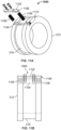
FIGs. 10 ,11A and 11B depict an example barbell scale in accordance with implementations of the present disclosure. - Like reference numbers and designations in the various drawings indicate like elements.
-
FIG. 1 depicts an example mobileweight training system 100 in accordance with implementations of the present disclosure. Thesystem 100 includes acollapsible barbell 102, a set ofweight holders 104, a system offiller bags 106, and acase 108 that can double as a weight-bench. Thefiller bags 106 can be filled with various readily available materials such as, but not limited to, sand, dirt, water, or gravel, and attached to theweight holders 104 to create weights for use with the barbell. Theweight holders 104 can be attached to thebarbell 102 by wrapping theweight holders 104 around the ends of thebarbell 102 or, in some examples, by hanging theweight holders 104 from the barbell using a handle on the weight holder 104 (e.g., as shown inFIGs. 2D and9C ). - The system of
filler bags 106 can includeseveral filler bags 106 of different sizes, each size designed to hold an approximate weight of material (e.g., 5, 10, and 15 pounds, wherein 1 Pound corresponds to 0,45kg). For example, such a mobileweight training system 100 can includeenough weight holders 104 andfiller bags 106 to produce 270 pounds of weight when filled (e.g., 6 weight holders, 12 - 15lb bags, 6 - 10lb bags, and 6 - 5lb bags, wherein 1 lb corresponds to 0,45kg), but with a travel weight (e.g., weight of the system with empty filler bags) not much greater that the weight of thebarbell 102 alone. -
FIGs. 2A-2D depict various views of an examplemobile barbell 102 in accordance with implementations of the present disclosure.FIGs. 2A-2C show various configurations of thebarbell 102, andFIG. 2D shows thebarbell 102 withweight holders 104 attached. Referring first toFIGs. 2A-2C , thebarbell 102 can be broken down into three separate parts (202, 204, 206) for storage and travel. The parts include two end portions (female end portion 202 and male end portion 204) and amiddle portion 206. Eachend portion male coupling 210a (male end portion 204) or afemale coupling 210b (female end portion 202). Themiddle section 206 has amale coupling 210a at one end and afemale coupling 210b the opposite end. Thecouplings end portions middle portion 206. Specifically, to assemble thebarbell 102, themale coupling 210a on themale end portion 204 fastens to thefemale coupling 210b of themiddle portion 206, and thefemale coupling 210b offemale end portion 202 fastens to themale coupling 210a of themiddle portion 206. As described in more detail below in reference toFIGs. 5, 6A, and 6B , thecouplings barbell 102 together. -
FIGs. 3A-3C and 4A-4C depict detail and perspective views, respectively, of each of the parts (portions barbell 102.FIGs. 3A and 4A show detail and perspective views of thefemale end portion 202. Thefemale end portion 202 includes acollar 212 and a hollowcylindrical sleeve 214 attached coaxially to thefemale end portion 202. Either thecollar 212, thesleeve 214, or both can be attached to thefemale end portion 202 such that they are free to rotate around thefemale end portion 202. For example, thecollar 212 andsleeve 214 can be mounted on bearings (e.g., brass bushings) placed between thefemale end portion 202, and the collar andsleeve 214. In some examples, thecollar 212 and thesleeve 214 can form a single assembly, for example, by affixing thecollar 212 to the sleeve (e.g., by welding or press fitting the two together). In some implementations, thesleeve 214 andcollar 212 can be formed in one piece. For example, thesleeve 214 andcollar 212 be machined from one piece of material. - In some examples, a seal 218 (e.g., a gasket or V-seal) can be placed between the
female end portion 202 and thecollar 212, and/or between thefemale end portion 202 and thesleeve 214 to prevent debris from fouling the bearings and impeding the rotation of thecollar 212 and/or thesleeve 214. In some examples, the V-seal is mounted axially on the bar, with a lip in contact with the bushing inside the collar/sleeve assembly to prevent debris from fouling the bushing from the interior side of the collar/sleeve assembly. -
FIGs. 3B and 4B show detail and perspective views of themale end portion 204. Themale end portion 204 includes acollar 212 and a hollowcylindrical sleeve 214 attached coaxially to themale end portion 204. Either thecollar 212, thesleeve 214, or both can be attached to themale end portion 204 such that they are free to rotate around thefemale end portion 204. For example, thecollar 212 andsleeve 214 can be mounted on bearings placed betweenmale end portion 204, and the collar andsleeve 214. As noted above, in some examples, thecollar 212 and thesleeve 214 can form a single assembly, for example, by affixing thecollar 212 to the sleeve (e.g., by welding or press fitting the two together). In some implementations, thesleeve 214 andcollar 212 can be formed in one piece. For example, thesleeve 214 andcollar 212 be machined from one piece of material.. - In some examples, a seal 218 (e.g., a gasket or v-seal) can be placed between the
male end portion 204 and thecollar 212, and/or betweenmale end portion 204 and thesleeve 214 to prevent debris from fouling the bearings and impeding the rotation of thecollar 212 and/or thesleeve 214. In some examples, the V-seal is mounted axially on the bar, with a lip in contact with the bushing inside the collar/sleeve assembly to prevent debris from fouling the bushing from the interior side of the collar/sleeve assembly. - As shown in
FIG. 2D , theweight holders 104 are attached to thesleeves 214 of thebarbell 102. Further, thesleeves 214 can have a diameter similar to industry standard Olympic barbell sleeves of, for example, 1 and 31/32 inches, such that thebarbell 102 can be used with standard weights in addition to theweight holders 104. In addition to serving as a stopper for weights placed on thesleeves 214, thecollars 212 can serve as a hanger for additional weight holders 104 (e.g., as shown inFIG. 2D ). For example, referring again toFIGs. 3A-3B and 4A-4B , thecollar 212 has achannel 216 formed in the outer surface and running along the circumference of thecollar 212. Thechannel 216 can be sized to cradle a handle on theweight holders 104, thereby preventing aweight holder 104 hung from thebarbell 102 from sliding during lifts. - In some implementations, as shown in
FIG. 2B , thebarbell 102, when fully assembled, has standard Olympic dimensions, for example, 2.2m (7.2ft) long and weighing 20kg (44lb), however, implementations may vary in weight and length, for example, to suit differing training routines. In some implementations, thebarbell 102 can be slightly longer than an Olympic barbell, for example, to accommodate thelonger weight holders 104 thesleeves 214 can be extended an appropriate distance, as compared to a standard Olympic barbell. In addition, the twoend portions middle portion 206 by, for example, coupling the respective male 210a and female 210b couplings of the male 204 and female 202 end portions together to form ashorter barbell 102, for example, a curl bar (as shown inFIG. 2C ). - Although a
barbell 102 made up of three separate portions (202, 204, 206) is shown, in some examples, thebarbell 102 can be made of more than three portions to, for example, make thebarbell 102 even more compact for travel and storage. For example, as shown inFIGs. 3C and 4C , which show detail and perspective views of example middle portions, themiddle portion 206 can be formed from two separatemiddle portions middle portion middle portions middle portions -
FIG. 5 depicts example threading configurations that can be used as coupling mechanisms for the male 210a and female 210b couplings. Threadingconfigurations portion 204, 206) along only a portion themale coupling 210a. Further, threadingconfiguration 502 shows a finer thread pitch than that of threadingconfiguration 504. Also, threadingconfigurations configurations male coupling 210a is at the distal end (e.g., the end away from thebarbell portion 204, 206). In other words, the unthreaded portion of themale coupling 210a is proximate to thebarbell portion male coupling 210a is at the distal end of themale portion 210a. -
Threading configuration 506 shows an example threading configuration in which the threads extend along the entire length of themale coupling 210a. Further, threadingconfiguration 506 represents a full-bodied threading configuration (e.g., a configuration in which the shank of the male coupling has a diameter equal to the maj or diameter of the threads). Although not shown, thefemale couplings 210b are tapped with corresponding thread grooves. -
FIGs. 6A and 6B depict another example coupling mechanism for the male 210a and female 210b couplings. Referring first toFIG. 6A, FIG. 6A shows a cross-sectional view of a pin and hole type ofcoupling mechanism 600. The male 210a andfemale coupling 210b each have correspondingholes male coupling 210a is inserted into thefemale coupling 210b. The twocouplings pins 602 inserted through the alignedholes - In some implementations, the
holes 604 in themale coupling 210a can be tapped to accept a spring andplunger assembly 650. Theassembly 650 includes a threadedbody 652 and amovable plunger 654 held under spring pressure by a spring (not shown) within thebody 652. Theplunger 654 can be moved into thebody 652 against the spring pressure. When theassembly 650 is installed in themale coupling 210a, the plunger extends past the outer circumference of themale coupling 210a and can lock into acorresponding hole 606 in thefemale coupling 210b. In some examples, theassembly 650 can include a thread locking element 656 (e.g., nylon, thread locking tape, or thread locking liquid). -
FIG. 7 depicts anexample weight holder 104 in accordance with implementations of the present disclosure. A front side of theweight holder 104 is shown inFIG. 7 . Theweight holder 104 is made of a strong but flexible material, for example, a fabric such as 1000 Denier Mil-Spec Cordura Nylon or other appropriate high strength fabric. Theweight holder 104 has severalsealable chambers 702 in which weights (e.g., filler bags 106) can be inserted. Thechambers 702 have anopening 704 at one end, and aclosure mechanism 706. Theclosure mechanism 706 can be, for example, a zipper or a flap with a fastening device such as, but not limited to, hook and loop fasteners, snaps, metal or plastic clips. In some examples, eachchamber 702 has a separate closure mechanism (e.g., a separate flap). In some examples, theweight holder 104 has a single closure mechanism 706 (e.g., a single flap) that encloses all of thechambers 702. - The
weight holder 104 has one ormore straps 708 and correspondingstrap fastening devices 710. Thestraps 708 are attached to an end of theweight holder 104 that is transverse to the orientation of thechambers 702, and thestrap fastening devices 710 are attached at an opposite end of theweight holder 104, also transvers to the orientation of thechambers 702. Thestraps 708 andstrap fastening devices 710 are positioned on theweight holder 104 such that, when thestraps 708 are secured to correspondingstrap fastening devices 710, the weight holder is wrapped into a hollow cylindrical shape (e.g., seeFIGs. 8B and9C ), thereby allowingweight holders 104 to be wrapped around thesleeve 214 of abarbell 102. In some examples, the weight holder is made to lie flat when not wrapped into the cylinder shape, for example, making the weight holder more space-efficient during storage. In some examples, thestrap fastening devices 710 can be hook or loop fasteners corresponding to respective loop or hook fasteners on thestraps 708. In some examples, thestrap fastening devices 710 can be fastening devices such as, but not limited to, double D-ring loops, buckles, S-hook straps, ladder lock buckles, metal or plastic clips (e.g., corresponding clips on the straps 708), or snaps. - In some implementations, the
weight holder 104 has threechambers 702, and the chambers are oriented on the weight holder such that, when theweight holder 104 is rolled up and thestraps 708 secured, theweight holder 104 has a triangular cross-section (e.g., as shown inFIGs. 8B and9C ). In some examples, design (e.g., the cross section) of the weight holder 104 (when wrapped) makes the weight holder self-tightening around thebarbell sleeves 214. In some implementations, eachchamber 702 of theweight holder 104 is sized to hold fifteen pounds of filler bags 106 (e.g., 1 - 15lb filler bag; 1 - 10lb and 1 - 5lb filler bag; or 3 - 5lb filler bags), with a total fillable weight of 45lbs. - In some examples, the
weight holder 104 includes one ormore handles -
FIGs. 8A and 8B depictexample filler bags 106 and anexample weight holder 104 in accordance with implementations of the present disclosure.FIG. 8A shows a back side of theweight holder 104 andfiller bags 106 being inserted into theweight holder 104.FIG. 8B shows anexample weight holder 104 loaded withfiller bags 106 and rolled up to be placed on an end of abarbell 102. For example, in order to attach thestraps 708 to thestrap fastening devices 710, theweight holder 104 is rolled into a cylindrical shape. More specifically,FIG. 8A showsfiller bags 106 being inserted into thechambers 702 of aweight holder 104. For example, 15lb filler bags are shown as being inserted into chambers A and B, and a 10lb and a 5lb filler bag are shown as being inserted into chamber C, for a total weight of 45lbs. When aweight holder 104 is filled with a desired weight offiller bags 106, theweight holder 104 can be rolled into the configuration shown inFIG. 8B by attaching thestraps 708 to correspondingstrap fastening devices 710.. - The
filler bags 106 are made of a high strength flexible material such as, for example, 1000 Denier Mil-Spec Cordura Nylon. Thefiller bags 106 also have aclosure mechanism 802, for example, similar to theclosure mechanism 706 of theweight holder 104. Theclosure mechanism 802 can be, for example, a zipper or a flap with a fastening device such as, but not limited to, hook and loop fasteners, snaps, metal or plastic clips. In some examples, thefiller bags 106 can have adouble closure mechanism 802. For example, the filler bags can have two overlappingclosure mechanisms 802 of the same (e.g., overlapping flaps with hook and loop fasteners) or different type (e.g., a zipper and a flap with hook and loop fasteners). In some examples, thefiller bags 106 may have a water tight liner and watertight closure 802 such that thefiller bags 106 can be filled with water. In some examples, thefiller bags 106 can have a handle attached to an outer surface of the bag. -
FIGs. 9A-9C depict various methods of attachingweight bags 104 to abarbell 102 in accordance with implementations of the present disclosure.FIG. 9A shows oneweight holder 104 attached at each end of thebarbell 102. For example, theweight holders 104 are wrapped around thesleeves 214 of thebarbell 102. Thestraps 708 can be pulled snug and attached to thestrap fastening devices 710 to securely fasten theweight holders 104 to thebarbell 102. -
FIG. 9B shows abarbell 102 with fourweight holders 104 attached. In some implementations, the straps of theweight holders 104 are long enough thatweight holders 104 can be wrapped around each other on abarbell sleeve 214. The first twoweight holders 104 are attached as described above in reference toFIG. 9A . Each of the second twoweight holders 104 are then wrapped around one of the first twoweight holders 104 previously attached to thebarbell sleeves 214. -
FIG. 9C shows abarbell 102 with sixweight holders 104 attached (e.g., a third set of two weight holders 104). In this example, aweight holder 104 is hung on eachcollar 212 of the barbell. For example, theweight holders 104 can be hung on thecollars 212 by placing one of the weight holder handles 712 in thechannel 216 of thecollar 212. Thecollar channel 216 preventsweight holders 104 hung in this fashion from sliding during lifts. -
FIG. 10 depicts anexample barbell scale 1000. In some implementation, thescale 1000 may be attached to or integrated with abarbell 102. For example, thescale 1000 can be attached to or integrated with thecollar 212 on either themale portion 204, thefemale portion 202, or both. In some implementations, thescale 1000 can be a mechanical scale, as shown inFIGs. 11A and 11B . For example, thescale 1000 can include amoveable element 1102 positioned in anotch 1104 of thecollar 212.Springs 1106 are positioned between an inner surface of thenotch 1104 and themoveable element 1102. When aweight holder 104 is hung on the collar 212 (e.g., as shown inFIG. 9C ), the weight of the weight holder compresses thesprings 1106, thereby translating themoveable element 1102 within thenotch 1104. Atab 1108 of themoveable element 1102 extends through a side surface of thecollar 212 and can serve as a pointer to a calibrated set ofweight markings 1110 on the side of thecollar 212. - In some implementations, the
scale 1000 in pressure sensing device includes anelectronic pressure sensor 1002 in electronic communication with anelectronic display device 1006, for example, through adetachable wire 1004. Theelectronic display device 1006 includes one or more processors and a data store storing instructions for processing electrical signals from the electronicpressure sensing device 1002 and displaying a weight. In some examples, the display device can be a mobile computing device such as, for example, a tablet computer or a smartphone. In such implementations, an application executed by the mobile computing device can process the signals from the electronic pressure sensor and display a weight. In some examples, theelectronic pressure sensor 1102 can be integrated with a mechanical scale, such as shown inFIGs. 11A and 11B . - While a number of examples have been described for illustration purposes, the foregoing description is not intended to limit the scope of the invention, which is defined by the scope of the appended claims.
Claims (20)
- A barbell comprising:a first end portion (202, 204) including a first collar (212) and a first hollow cylindrical sleeve (214) coaxially attached to the first end portion, wherein the first collar (212) and the first sleeve (214) form a first single assembly or are formed in a first single piece;a second end portion (202, 204);one or more seals (218) placed between the first end portion (202, 204) and the collar (212), and/or between the first end portion (202, 204) and the sleeve (214); anda middle portion (206, 206a, 206b) couplable to the first end portion and the second end portion, the middle portion comprising:a male coupling extending from a first end of the middle portion, the male coupling providing a first coupling mechanism that engages with a corresponding female coupling of the first end portion, anda female coupling extending from a second end of the middle portion, the female coupling providing a second coupling mechanism that engages with a corresponding male coupling of the second end portion.
- The barbell of claim 1, wherein the first end portion is configured to hold a weight at an end of the first end portion opposite the female coupling on the first end portion, and wherein the second end portion is configured to hold a weight at an end of the second end portion opposite the male coupling on the second end portion.
- The barbell of claim 1, wherein the first collar (212) has a first channel formed around an outer circumference of the first collar.
- The barbell of claim 1, wherein the first and second coupling mechanisms are threading, and wherein the threading extends from the first end of the middle portion (206, 206a, 206b) along only a portion of a length of the male coupling.
- The barbell of any one of claims 1 to 4, wherein the first and second coupling mechanisms include: plunger buttons and corresponding holes, pins, or locking sleeves.
- The barbell of any one of claims 1 to 5, further comprising one or more seals (218) placed between the second end portion (202, 204) and the collar (212), and/or between the second end portion (202, 204) and the sleeve (214).
- The barbell of any one of claims 1 to 6, wherein each of the one or more seals (218) comprisesa gasket, ora V-seal, optionally wherein the V-seal is mounted axially on a respective first or second end portion (202, 204), or with a lip in contact with a respective bushing inside the respective collar (212) and/or sleeve (214).
- The barbell of claim 1, wherein the female coupling of the first end portion and the male coupling of the second end portion are corresponding couplings so as to couple the first end portion with the second end portion without the middle portion (206, 206a, 206b).
- The barbell of any one of claims 1 to 8, wherein the first collar (212) and the first sleeve (214) form the first single assembly, and the first single assembly is formed by affixing the first collar (212) to the first sleeve (214) by welding or press fitting.
- The barbell of any one of claims 1 to 8, wherein the first collar (212) and the first sleeve (214) form the first single piece, and the first collar (212) and the first sleeve (214) are machined from one piece of material to form the first single piece.
- The barbell of any one of claims 1 to 10, wherein the first collar (212) and the first hollow cylindrical sleeve (214) are attachable to the first end portion (202) such that they are free to rotate around the first end portion.
- The barbell of any one of claims 1 to 11, wherein the second end portion (202, 204) includes a second collar (212) and a second hollow cylindrical sleeve (214) coaxially attached to the second end portion, and the second collar (212) and the second sleeve (214) form a second single assembly or are formed in a second single piece.
- The barbell of claim 12, wherein the second collar (212) has a second channel formed around an outer circumference of the second collar.
- The barbell of any one of claims 12 or 13, wherein the second collar (212) and the second sleeve (214) form the second single assembly, and the second single assembly is formed by affixing the second collar (212) to the second sleeve (214) by welding or press fitting.
- The barbell of any one of claims 12 to 13, wherein the second collar (212) and the second sleeve (214) form the second single piece, and the second collar (212) and the second sleeve (214) are machined from one piece of material to form the second single piece.
- The barbell of any one of claims 12 to 15, wherein the second collar (212) and the second hollow cylindrical sleeve (214) are attachable to the second end portion (202) such that they are free to rotate around the second end portion.
- The barbell of any one of claims 1 to 16, wherein the first end portion (202, 204) and the second end portion (202, 204) are configured to form a bar, optionally in combination with the middle portion (206, 206a, 206b).
- The barbell of any one of claims 1 to 16, wherein the first end portion (202, 204) and the second end portion (202, 204) are configured to be fastened together without the middle portion (206, 206a, 206b).
- The barbell of claim 18, wherein the first end portion (204) has a male coupling (210a) and the second end portion (202) has a female coupling (210b), and the first end portion (204) and the second end portion (202) are fastened together by coupling the male coupling of the first end portion to the female coupling of the second end portion to form a bar.
- The barbell of any one of claims 1 to 19, further comprising a first middle portion (206a) and a second middle portion (206b) configured to form the middle portion (206); optionally wherein the first and second middle portions (206a, 206b) have different lengths; further optionally wherein the first end portion (204) and the second end portion (202) are configured to form a bar using one or both of the first and second middle portions (206a, 206b).
Applications Claiming Priority (3)
| Application Number | Priority Date | Filing Date | Title |
|---|---|---|---|
| US201562158498P | 2015-05-07 | 2015-05-07 | |
| EP16790078.6A EP3291892B1 (en) | 2015-05-07 | 2016-05-05 | Mobile weight training system |
| PCT/US2016/030962 WO2016179380A1 (en) | 2015-05-07 | 2016-05-05 | Mobile weight training system |
Related Parent Applications (2)
| Application Number | Title | Priority Date | Filing Date |
|---|---|---|---|
| EP16790078.6A Division EP3291892B1 (en) | 2015-05-07 | 2016-05-05 | Mobile weight training system |
| EP16790078.6A Division-Into EP3291892B1 (en) | 2015-05-07 | 2016-05-05 | Mobile weight training system |
Publications (4)
| Publication Number | Publication Date |
|---|---|
| EP3791938A2 EP3791938A2 (en) | 2021-03-17 |
| EP3791938A3 EP3791938A3 (en) | 2021-06-02 |
| EP3791938C0 EP3791938C0 (en) | 2025-01-01 |
| EP3791938B1 true EP3791938B1 (en) | 2025-01-01 |
Family
ID=57218375
Family Applications (2)
| Application Number | Title | Priority Date | Filing Date |
|---|---|---|---|
| EP20204244.6A Active EP3791938B1 (en) | 2015-05-07 | 2016-05-05 | Mobile weight training system |
| EP16790078.6A Active EP3291892B1 (en) | 2015-05-07 | 2016-05-05 | Mobile weight training system |
Family Applications After (1)
| Application Number | Title | Priority Date | Filing Date |
|---|---|---|---|
| EP16790078.6A Active EP3291892B1 (en) | 2015-05-07 | 2016-05-05 | Mobile weight training system |
Country Status (4)
| Country | Link |
|---|---|
| US (3) | US10493313B2 (en) |
| EP (2) | EP3791938B1 (en) |
| ES (1) | ES3002957T3 (en) |
| WO (1) | WO2016179380A1 (en) |
Families Citing this family (21)
| Publication number | Priority date | Publication date | Assignee | Title |
|---|---|---|---|---|
| US10744366B1 (en) * | 2015-02-05 | 2020-08-18 | Albert Sorin | Collapsible weightlifting bar and methods of manufacture and use |
| US10493313B2 (en) | 2015-05-07 | 2019-12-03 | Xmt Solutions Llc | Mobile weight training system |
| USD831762S1 (en) * | 2016-10-21 | 2018-10-23 | Fitbench Llc | Combined workout and storage bench |
| US10092791B2 (en) * | 2016-10-26 | 2018-10-09 | Fitbench Llc | Workout bench |
| US10960256B2 (en) | 2016-10-26 | 2021-03-30 | Fitbench | Multipurpose workout and storage bench |
| US20230145445A1 (en) * | 2016-11-15 | 2023-05-11 | Initiate Launch, Llc | Kettle bell and methods of use thereof |
| GB2559323B (en) * | 2017-01-25 | 2020-04-29 | High Street Tv Group Ltd | Multiple movement exercise device |
| US11027166B1 (en) * | 2017-12-20 | 2021-06-08 | Kenroy Anthony Francis | Portable weight-based exercise system and method |
| US10843028B2 (en) * | 2018-06-22 | 2020-11-24 | Mark Nalley | Electronically actuated dumbbell weight training device having selectively connected weight plates |
| US11857826B2 (en) * | 2018-07-18 | 2024-01-02 | Abraham Freig | Versatile weight bar assembly |
| US20240123277A1 (en) * | 2018-07-18 | 2024-04-18 | Abraham Freig | Weight Bar Exercise Apparatus |
| US20210331021A1 (en) * | 2018-07-18 | 2021-10-28 | Abraham Freig | Weight Bar Assembly |
| US11364407B2 (en) | 2018-10-19 | 2022-06-21 | Coulter Ventures, Llc. | Connector assembly |
| USD885864S1 (en) * | 2018-10-19 | 2020-06-02 | Coulter Ventures, Llc. | Locking pin |
| WO2020167596A1 (en) * | 2019-02-11 | 2020-08-20 | Keith Cyzen | Travel exercise equipment assemblies |
| US11007393B2 (en) | 2019-06-28 | 2021-05-18 | Nucleus Core Llc | Variable weight equipment with liquid resistance |
| US20210331027A1 (en) * | 2020-04-28 | 2021-10-28 | Andrew John Mizzoni | Exercise apparatus |
| US20230026251A1 (en) * | 2021-07-22 | 2023-01-26 | Nautilus, Inc. | Exercise system with translatable and rotatable display |
| CN113713357B (en) * | 2021-08-19 | 2022-06-21 | 湖南机电职业技术学院 | Sports goods rack and sports goods subassembly |
| US12324945B1 (en) * | 2024-05-08 | 2025-06-10 | Cap Barbell, Inc. | Exercise bar connector assembly |
| US12465804B1 (en) * | 2024-05-08 | 2025-11-11 | Cap Barbell, Inc. | Exercise bar connector assembly |
Family Cites Families (40)
| Publication number | Priority date | Publication date | Assignee | Title |
|---|---|---|---|---|
| US113966A (en) | 1871-04-25 | Improvement in dumb-bells | ||
| US1536048A (en) | 1923-09-17 | 1925-05-05 | Wiljo U Alastalo | Hand bar for physical training |
| US3185476A (en) | 1962-08-30 | 1965-05-25 | Walter W Fechner | Spherical ball including an internal resilient hand grip |
| GB1217328A (en) * | 1967-07-24 | 1970-12-31 | Apollo Distributors Ltd | Exercising device |
| US3726522A (en) * | 1971-05-17 | 1973-04-10 | Diversified Prod Corp | Combination of a barbell with weight and collet device |
| US3781007A (en) * | 1972-11-01 | 1973-12-25 | R Baker | Sectional,folding,combination dumbell-bar bell |
| US4029312A (en) | 1975-12-22 | 1977-06-14 | Wright Forrest S | Exercising device |
| US7878952B2 (en) | 2008-06-24 | 2011-02-01 | Fenelon Paul J | Balanced circular free weights |
| US4743016A (en) * | 1985-10-07 | 1988-05-10 | Derworp Mary K Van | Variable therapeutic and exercise weights |
| US4896880A (en) | 1987-09-14 | 1990-01-30 | Dar Products Corporation | Exercise devices |
| US4911434A (en) * | 1989-01-26 | 1990-03-27 | Herring Wesley B | Weight apparatus for exercising |
| US5314394A (en) * | 1991-12-31 | 1994-05-24 | Ronan John J | Spotting apparatus for assisting a weightlifter |
| US5300001A (en) * | 1993-05-03 | 1994-04-05 | Sealy Anthony J | Portable dumbbell apparatus |
| US5868652A (en) * | 1996-07-08 | 1999-02-09 | Spletzer; David E. | Exercise thigh weight system |
| US6123651A (en) * | 1998-02-24 | 2000-09-26 | Ultima Fitness, Inc. | Barbell holder and methods for its use |
| US5997442A (en) * | 1998-05-15 | 1999-12-07 | Cordes; Richard A. | Portable multi-purpose exercise system |
| US6099441A (en) * | 1998-12-28 | 2000-08-08 | Bonnet; Darrell B. | Water weight exercise kit |
| US8343019B2 (en) * | 2001-10-15 | 2013-01-01 | Issac Friend | Tai Chi yoga bag |
| US20030130070A1 (en) * | 2002-01-07 | 2003-07-10 | Nolan Timothy J. | Adjustable weight training belt |
| EP1858601B1 (en) | 2004-04-14 | 2010-11-24 | Long's Striking Tiger Kenpo Karate, Inc. | Hammer head training target |
| US20070099772A1 (en) * | 2005-11-02 | 2007-05-03 | David Fu | Adjustable punching bag |
| GB2441977B (en) * | 2006-06-13 | 2008-05-28 | Escape Fitness Ltd | An exercise device |
| US7674214B2 (en) * | 2007-10-01 | 2010-03-09 | David Marethouse | Barbell handles |
| US7828703B1 (en) * | 2008-03-07 | 2010-11-09 | Boesch Don E | Portable exercise device |
| US7585262B1 (en) | 2008-10-27 | 2009-09-08 | Vladimir Vayntraub | Convex push-up handles |
| GB201005728D0 (en) * | 2010-04-07 | 2010-05-19 | Swain Edmund | Dumbbell |
| US8047974B1 (en) * | 2010-08-03 | 2011-11-01 | Kanelos Stephen A | Exercise apparatus and methods of assembling and using the same |
| US8672815B1 (en) * | 2011-11-09 | 2014-03-18 | Jonathan C. Springer | Barbell system |
| US9126079B2 (en) * | 2012-07-12 | 2015-09-08 | Edward M. Jordan | Adapter for exercise bar |
| US20140155234A1 (en) * | 2012-12-04 | 2014-06-05 | Jeffrey Justice | Wraps For Improving Grip On Exercise Equipment |
| US10874896B1 (en) * | 2013-05-06 | 2020-12-29 | Anthony A. Little | Exerciser device |
| US20150038302A1 (en) * | 2013-08-02 | 2015-02-05 | Andrew Daniel O'Brien | Weightlifting Barbell |
| GB2522257A (en) * | 2014-01-20 | 2015-07-22 | Escape Fitness Ltd | A weight training apparatus |
| US9776032B2 (en) * | 2014-06-20 | 2017-10-03 | Nautilus, Inc. | Adjustable dumbbell system having a weight sensor |
| CN106659921B (en) * | 2014-08-28 | 2019-01-04 | 爱康保健健身有限公司 | Weight selector relieving mechanism |
| US10143885B2 (en) * | 2015-03-13 | 2018-12-04 | William James DuMee | Portable exercise device for resistance exercises |
| US9314661B1 (en) * | 2015-04-10 | 2016-04-19 | Jih Ming CHEN | Pivotal unit for barbell |
| US10493313B2 (en) | 2015-05-07 | 2019-12-03 | Xmt Solutions Llc | Mobile weight training system |
| US10039949B2 (en) * | 2015-06-23 | 2018-08-07 | Prx Performance, Llc | Barbell collar system |
| US10092791B2 (en) * | 2016-10-26 | 2018-10-09 | Fitbench Llc | Workout bench |
-
2016
- 2016-05-05 US US15/572,421 patent/US10493313B2/en active Active
- 2016-05-05 WO PCT/US2016/030962 patent/WO2016179380A1/en not_active Ceased
- 2016-05-05 EP EP20204244.6A patent/EP3791938B1/en active Active
- 2016-05-05 EP EP16790078.6A patent/EP3291892B1/en active Active
- 2016-05-05 ES ES20204244T patent/ES3002957T3/en active Active
-
2019
- 2019-12-02 US US16/700,694 patent/US11369827B2/en active Active
-
2022
- 2022-06-27 US US17/850,460 patent/US11857828B2/en active Active
Also Published As
| Publication number | Publication date |
|---|---|
| EP3291892A1 (en) | 2018-03-14 |
| EP3791938A2 (en) | 2021-03-17 |
| EP3791938A3 (en) | 2021-06-02 |
| US11369827B2 (en) | 2022-06-28 |
| EP3291892A4 (en) | 2019-06-05 |
| US20180133538A1 (en) | 2018-05-17 |
| WO2016179380A1 (en) | 2016-11-10 |
| US11857828B2 (en) | 2024-01-02 |
| EP3791938C0 (en) | 2025-01-01 |
| EP3291892B1 (en) | 2021-05-05 |
| US10493313B2 (en) | 2019-12-03 |
| US20220401788A1 (en) | 2022-12-22 |
| US20200101344A1 (en) | 2020-04-02 |
| ES3002957T3 (en) | 2025-03-10 |
Similar Documents
| Publication | Publication Date | Title |
|---|---|---|
| US11857828B2 (en) | Mobile weight training system | |
| US10343009B2 (en) | Multi-use exercise bag with removeable weights | |
| US20130190144A1 (en) | Weighted Vest | |
| US9700122B2 (en) | Central osteoarticular relief and performance structured load distribution system device and modular scalable vest system | |
| US20190041167A1 (en) | Load bearing harness | |
| US20160367848A1 (en) | Modular Weight Vest | |
| US20080127461A1 (en) | Multiple purpose strap-pack system | |
| EP3945911B1 (en) | Vest assembly | |
| US11666794B2 (en) | Weight training vest | |
| US11786416B2 (en) | Quick release, back carry, first aid kit | |
| EP2926870A1 (en) | A weight training apparatus | |
| US20160128394A1 (en) | Vest garment with multi-purpose, universal hydration system carrier compartment | |
| US20130316880A1 (en) | Adjustable Apparatus for Addition of Weights to Dumbbells | |
| US20180056107A1 (en) | Multifunctional Lumbar Support Harness | |
| US9427069B1 (en) | Drill holster | |
| EP2803391B1 (en) | Accessory for gymnastic exercises | |
| US12588715B2 (en) | Multi-functional vest with integrated weight and hydration features | |
| US20090057358A1 (en) | Reusable, adjustable carriers for toting awkward handle-less items and related methods | |
| HK40044759B (en) | Mobile weight training system | |
| US12478821B2 (en) | Weight exercise system and apparatus | |
| HK40044759A (en) | Mobile weight training system | |
| US11096471B2 (en) | Carrying device | |
| US20120292355A1 (en) | Piggyback duffel | |
| US11330878B2 (en) | Sports bag | |
| US20260033560A1 (en) | Wearable vest for holding one or more articles |
Legal Events
| Date | Code | Title | Description |
|---|---|---|---|
| PUAI | Public reference made under article 153(3) epc to a published international application that has entered the european phase |
Free format text: ORIGINAL CODE: 0009012 |
|
| STAA | Information on the status of an ep patent application or granted ep patent |
Free format text: STATUS: REQUEST FOR EXAMINATION WAS MADE |
|
| 17P | Request for examination filed |
Effective date: 20201028 |
|
| AC | Divisional application: reference to earlier application |
Ref document number: 3291892 Country of ref document: EP Kind code of ref document: P |
|
| AK | Designated contracting states |
Kind code of ref document: A2 Designated state(s): AL AT BE BG CH CY CZ DE DK EE ES FI FR GB GR HR HU IE IS IT LI LT LU LV MC MK MT NL NO PL PT RO RS SE SI SK SM TR |
|
| PUAL | Search report despatched |
Free format text: ORIGINAL CODE: 0009013 |
|
| AK | Designated contracting states |
Kind code of ref document: A3 Designated state(s): AL AT BE BG CH CY CZ DE DK EE ES FI FR GB GR HR HU IE IS IT LI LT LU LV MC MK MT NL NO PL PT RO RS SE SI SK SM TR |
|
| RIC1 | Information provided on ipc code assigned before grant |
Ipc: A63B 21/075 20060101AFI20210423BHEP Ipc: A63B 21/06 20060101ALI20210423BHEP Ipc: A63B 21/072 20060101ALI20210423BHEP |
|
| REG | Reference to a national code |
Ref country code: HK Ref legal event code: DE Ref document number: 40044759 Country of ref document: HK |
|
| STAA | Information on the status of an ep patent application or granted ep patent |
Free format text: STATUS: EXAMINATION IS IN PROGRESS |
|
| 17Q | First examination report despatched |
Effective date: 20231102 |
|
| REG | Reference to a national code |
Ref country code: DE Ref legal event code: R079 Free format text: PREVIOUS MAIN CLASS: A63B0021075000 Ipc: A63B0021000000 Ref country code: DE Ref legal event code: R079 Ref document number: 602016090857 Country of ref document: DE Free format text: PREVIOUS MAIN CLASS: A63B0021075000 Ipc: A63B0021000000 |
|
| GRAP | Despatch of communication of intention to grant a patent |
Free format text: ORIGINAL CODE: EPIDOSNIGR1 |
|
| STAA | Information on the status of an ep patent application or granted ep patent |
Free format text: STATUS: GRANT OF PATENT IS INTENDED |
|
| RIC1 | Information provided on ipc code assigned before grant |
Ipc: A63B 21/00 20060101AFI20240805BHEP |
|
| INTG | Intention to grant announced |
Effective date: 20240819 |
|
| GRAS | Grant fee paid |
Free format text: ORIGINAL CODE: EPIDOSNIGR3 |
|
| GRAA | (expected) grant |
Free format text: ORIGINAL CODE: 0009210 |
|
| STAA | Information on the status of an ep patent application or granted ep patent |
Free format text: STATUS: THE PATENT HAS BEEN GRANTED |
|
| AC | Divisional application: reference to earlier application |
Ref document number: 3291892 Country of ref document: EP Kind code of ref document: P |
|
| AK | Designated contracting states |
Kind code of ref document: B1 Designated state(s): AL AT BE BG CH CY CZ DE DK EE ES FI FR GB GR HR HU IE IS IT LI LT LU LV MC MK MT NL NO PL PT RO RS SE SI SK SM TR |
|
| REG | Reference to a national code |
Ref country code: GB Ref legal event code: FG4D |
|
| REG | Reference to a national code |
Ref country code: CH Ref legal event code: EP |
|
| REG | Reference to a national code |
Ref country code: DE Ref legal event code: R096 Ref document number: 602016090857 Country of ref document: DE |
|
| REG | Reference to a national code |
Ref country code: IE Ref legal event code: FG4D |
|
| U01 | Request for unitary effect filed |
Effective date: 20250110 |
|
| U07 | Unitary effect registered |
Designated state(s): AT BE BG DE DK EE FI FR IT LT LU LV MT NL PT RO SE SI Effective date: 20250117 |
|
| REG | Reference to a national code |
Ref country code: ES Ref legal event code: FG2A Ref document number: 3002957 Country of ref document: ES Kind code of ref document: T3 Effective date: 20250310 |
|
| U20 | Renewal fee for the european patent with unitary effect paid |
Year of fee payment: 10 Effective date: 20250509 |
|
| PG25 | Lapsed in a contracting state [announced via postgrant information from national office to epo] |
Ref country code: PL Free format text: LAPSE BECAUSE OF FAILURE TO SUBMIT A TRANSLATION OF THE DESCRIPTION OR TO PAY THE FEE WITHIN THE PRESCRIBED TIME-LIMIT Effective date: 20250101 |
|
| PGFP | Annual fee paid to national office [announced via postgrant information from national office to epo] |
Ref country code: GB Payment date: 20250501 Year of fee payment: 10 Ref country code: ES Payment date: 20250605 Year of fee payment: 10 |
|
| PG25 | Lapsed in a contracting state [announced via postgrant information from national office to epo] |
Ref country code: IS Free format text: LAPSE BECAUSE OF FAILURE TO SUBMIT A TRANSLATION OF THE DESCRIPTION OR TO PAY THE FEE WITHIN THE PRESCRIBED TIME-LIMIT Effective date: 20250501 Ref country code: NO Free format text: LAPSE BECAUSE OF FAILURE TO SUBMIT A TRANSLATION OF THE DESCRIPTION OR TO PAY THE FEE WITHIN THE PRESCRIBED TIME-LIMIT Effective date: 20250401 |
|
| PG25 | Lapsed in a contracting state [announced via postgrant information from national office to epo] |
Ref country code: HR Free format text: LAPSE BECAUSE OF FAILURE TO SUBMIT A TRANSLATION OF THE DESCRIPTION OR TO PAY THE FEE WITHIN THE PRESCRIBED TIME-LIMIT Effective date: 20250101 |
|
| PG25 | Lapsed in a contracting state [announced via postgrant information from national office to epo] |
Ref country code: GR Free format text: LAPSE BECAUSE OF FAILURE TO SUBMIT A TRANSLATION OF THE DESCRIPTION OR TO PAY THE FEE WITHIN THE PRESCRIBED TIME-LIMIT Effective date: 20250402 |
|
| PG25 | Lapsed in a contracting state [announced via postgrant information from national office to epo] |
Ref country code: CZ Free format text: LAPSE BECAUSE OF FAILURE TO SUBMIT A TRANSLATION OF THE DESCRIPTION OR TO PAY THE FEE WITHIN THE PRESCRIBED TIME-LIMIT Effective date: 20250101 |
|
| PG25 | Lapsed in a contracting state [announced via postgrant information from national office to epo] |
Ref country code: SM Free format text: LAPSE BECAUSE OF FAILURE TO SUBMIT A TRANSLATION OF THE DESCRIPTION OR TO PAY THE FEE WITHIN THE PRESCRIBED TIME-LIMIT Effective date: 20250101 |
|
| PG25 | Lapsed in a contracting state [announced via postgrant information from national office to epo] |
Ref country code: SK Free format text: LAPSE BECAUSE OF FAILURE TO SUBMIT A TRANSLATION OF THE DESCRIPTION OR TO PAY THE FEE WITHIN THE PRESCRIBED TIME-LIMIT Effective date: 20250101 |
|
| PLBE | No opposition filed within time limit |
Free format text: ORIGINAL CODE: 0009261 |
|
| STAA | Information on the status of an ep patent application or granted ep patent |
Free format text: STATUS: NO OPPOSITION FILED WITHIN TIME LIMIT |
|
| REG | Reference to a national code |
Ref country code: CH Ref legal event code: L10 Free format text: ST27 STATUS EVENT CODE: U-0-0-L10-L00 (AS PROVIDED BY THE NATIONAL OFFICE) Effective date: 20251112 |
|
| 26N | No opposition filed |
Effective date: 20251002 |
|
| REG | Reference to a national code |
Ref country code: CH Ref legal event code: H13 Free format text: ST27 STATUS EVENT CODE: U-0-0-H10-H13 (AS PROVIDED BY THE NATIONAL OFFICE) Effective date: 20251223 |
|
| PG25 | Lapsed in a contracting state [announced via postgrant information from national office to epo] |
Ref country code: CH Free format text: LAPSE BECAUSE OF NON-PAYMENT OF DUE FEES Effective date: 20250531 |
|
| PG25 | Lapsed in a contracting state [announced via postgrant information from national office to epo] |
Ref country code: MC Free format text: LAPSE BECAUSE OF FAILURE TO SUBMIT A TRANSLATION OF THE DESCRIPTION OR TO PAY THE FEE WITHIN THE PRESCRIBED TIME-LIMIT Effective date: 20250101 |
|
| PG25 | Lapsed in a contracting state [announced via postgrant information from national office to epo] |
Ref country code: IE Free format text: LAPSE BECAUSE OF NON-PAYMENT OF DUE FEES Effective date: 20250505 |