EP3791016B1 - Wäschetrockner - Google Patents
Wäschetrockner Download PDFInfo
- Publication number
- EP3791016B1 EP3791016B1 EP18723480.2A EP18723480A EP3791016B1 EP 3791016 B1 EP3791016 B1 EP 3791016B1 EP 18723480 A EP18723480 A EP 18723480A EP 3791016 B1 EP3791016 B1 EP 3791016B1
- Authority
- EP
- European Patent Office
- Prior art keywords
- evaporator
- condenser
- laundry dryer
- laundry
- drum
- Prior art date
- Legal status (The legal status is an assumption and is not a legal conclusion. Google has not performed a legal analysis and makes no representation as to the accuracy of the status listed.)
- Active
Links
Images


Classifications
-
- D—TEXTILES; PAPER
- D06—TREATMENT OF TEXTILES OR THE LIKE; LAUNDERING; FLEXIBLE MATERIALS NOT OTHERWISE PROVIDED FOR
- D06F—LAUNDERING, DRYING, IRONING, PRESSING OR FOLDING TEXTILE ARTICLES
- D06F58/00—Domestic laundry dryers
- D06F58/20—General details of domestic laundry dryers
-
- D—TEXTILES; PAPER
- D06—TREATMENT OF TEXTILES OR THE LIKE; LAUNDERING; FLEXIBLE MATERIALS NOT OTHERWISE PROVIDED FOR
- D06F—LAUNDERING, DRYING, IRONING, PRESSING OR FOLDING TEXTILE ARTICLES
- D06F2103/00—Parameters monitored or detected for the control of domestic laundry washing machines, washer-dryers or laundry dryers
- D06F2103/50—Parameters monitored or detected for the control of domestic laundry washing machines, washer-dryers or laundry dryers related to heat pumps, e.g. pressure or flow rate
-
- D—TEXTILES; PAPER
- D06—TREATMENT OF TEXTILES OR THE LIKE; LAUNDERING; FLEXIBLE MATERIALS NOT OTHERWISE PROVIDED FOR
- D06F—LAUNDERING, DRYING, IRONING, PRESSING OR FOLDING TEXTILE ARTICLES
- D06F2103/00—Parameters monitored or detected for the control of domestic laundry washing machines, washer-dryers or laundry dryers
- D06F2103/58—Parameters monitored or detected for the control of domestic laundry washing machines, washer-dryers or laundry dryers related to condensation, e.g. condensate water level
-
- D—TEXTILES; PAPER
- D06—TREATMENT OF TEXTILES OR THE LIKE; LAUNDERING; FLEXIBLE MATERIALS NOT OTHERWISE PROVIDED FOR
- D06F—LAUNDERING, DRYING, IRONING, PRESSING OR FOLDING TEXTILE ARTICLES
- D06F2105/00—Systems or parameters controlled or affected by the control systems of washing machines, washer-dryers or laundry dryers
- D06F2105/26—Heat pumps
-
- D—TEXTILES; PAPER
- D06—TREATMENT OF TEXTILES OR THE LIKE; LAUNDERING; FLEXIBLE MATERIALS NOT OTHERWISE PROVIDED FOR
- D06F—LAUNDERING, DRYING, IRONING, PRESSING OR FOLDING TEXTILE ARTICLES
- D06F25/00—Washing machines with receptacles, e.g. perforated, having a rotary movement, e.g. oscillatory movement, the receptacle serving both for washing and for centrifugally separating water from the laundry and having further drying means, e.g. using hot air
-
- D—TEXTILES; PAPER
- D06—TREATMENT OF TEXTILES OR THE LIKE; LAUNDERING; FLEXIBLE MATERIALS NOT OTHERWISE PROVIDED FOR
- D06F—LAUNDERING, DRYING, IRONING, PRESSING OR FOLDING TEXTILE ARTICLES
- D06F58/00—Domestic laundry dryers
- D06F58/02—Domestic laundry dryers having dryer drums rotating about a horizontal axis
-
- D—TEXTILES; PAPER
- D06—TREATMENT OF TEXTILES OR THE LIKE; LAUNDERING; FLEXIBLE MATERIALS NOT OTHERWISE PROVIDED FOR
- D06F—LAUNDERING, DRYING, IRONING, PRESSING OR FOLDING TEXTILE ARTICLES
- D06F58/00—Domestic laundry dryers
- D06F58/20—General details of domestic laundry dryers
- D06F58/206—Heat pump arrangements
-
- D—TEXTILES; PAPER
- D06—TREATMENT OF TEXTILES OR THE LIKE; LAUNDERING; FLEXIBLE MATERIALS NOT OTHERWISE PROVIDED FOR
- D06F—LAUNDERING, DRYING, IRONING, PRESSING OR FOLDING TEXTILE ARTICLES
- D06F58/00—Domestic laundry dryers
- D06F58/20—General details of domestic laundry dryers
- D06F58/22—Lint collecting arrangements
-
- D—TEXTILES; PAPER
- D06—TREATMENT OF TEXTILES OR THE LIKE; LAUNDERING; FLEXIBLE MATERIALS NOT OTHERWISE PROVIDED FOR
- D06F—LAUNDERING, DRYING, IRONING, PRESSING OR FOLDING TEXTILE ARTICLES
- D06F58/00—Domestic laundry dryers
- D06F58/20—General details of domestic laundry dryers
- D06F58/24—Condensing arrangements
-
- D—TEXTILES; PAPER
- D06—TREATMENT OF TEXTILES OR THE LIKE; LAUNDERING; FLEXIBLE MATERIALS NOT OTHERWISE PROVIDED FOR
- D06F—LAUNDERING, DRYING, IRONING, PRESSING OR FOLDING TEXTILE ARTICLES
- D06F58/00—Domestic laundry dryers
- D06F58/32—Control of operations performed in domestic laundry dryers
Definitions
- the present invention relates to a domestic laundry-dryer, i.e. to a household device for drying laundry.
- a washer-dryer i.e. laundry dryer that can also wash laundry.
- WO 2017/174766 relates to a laundry washing and/or drying machine comprising a heat pump which is arranged in the rear part of the machine.
- EP 2 471 998 describes a laundry drying appliance with a heat pump arranged in the rear part of the machine. The evaporator can automatically be cleaned in order to remove possible fluff that is not retained by the defluff filter.
- the problem to be solved by the present invention is therefore to provide a compact domestic laundry dryer.
- the invention relates to a laundry dryer with a cabinet and a drum, wherein the drum is rotatably placed within the cabinet.
- the drum has an essentially cylindrical shape with the axis of the cylinder extending horizontally within the cabinet.
- the drum has an opening at its front side for loading the laundry, and it is closed at its back side, i.e. at the end of the drum facing away from the front side.
- the laundry dryer further comprises a heat pump with a condenser and an evaporator.
- the condenser and the evaporator are arranged on the back side of the drum.
- the laundry dryer further comprises an air circulating system connecting the drum to the condenser and the evaporator.
- the air circulating system comprises a ventilator configured to circulate the air in the system from the drum to the evaporator, the condenser, and back to the drum.
- the ventilator is located between the condenser and the drum, i.e . the air from the condenser passes the ventilator and then enters the drum.
- the laundry drier further comprises a control unit adapted and structured to control the operation of the individual components of the device.
- At least part of the condenser and of the evaporator are arranged at the back side of the drum.
- at least part of the condenser and the evaporator are arranged behind the drum. This allows to exploit space behind the drum.
- the condenser as well as the evaporator comprise plates for exchanging heat between the fluid ducts of the heat pump and the process air. Said plates can be aligned vertically.
- the shortest distance between individual plates of the condenser is larger than the shortest distance between individual plates of the evaporator.
- the distance between the plates of the condenser can be at least twice the distance between the plates of the evaporator.
- the laundry dryer is configured to be a washer-dryer with a tub.
- the drum is rotatably arranged in the tub.
- the tub retains the process water while washing the laundry.
- the condenser and the evaporator are arranged above each other.
- the condenser is positioned vertically above at least a part of the evaporator. In other words, when seen from above, the condenser and evaporator overlap.
- At least part of a lower end of the condenser is adjacent to at least part of an upper end of the evaporator.
- the lower end of the condenser fully aligns with the upper end of the evaporator.
- Arranging the evaporator below the condenser provides a compact design. Further, it prevents water from the evaporator from entering the condenser as well as from entering the parts of the air ducts that lead air from the condenser back to the drum.
- the condenser and/or the evaporator horizontally extends along at least 60%, in particular at least 75%, of the full width of the cabinet, therefore, exploiting the space within the cabinet.
- the width of the condenser and/or the evaporator is defined to be the widest extension of the condenser or evaporator in the horizontal direction perpendicular to the rotation axis of the drum.
- At least a section of the condenser and/or the evaporator is arranged horizontally behind the drum.
- at least part of the condenser and/or the evaporator is hidden behind it.
- the laundry dryer comprises a water trough arranged below the evaporator. It can be configured and positioned to collect water, in particular condensed water and/or rinsing water, from the evaporator and or condenser. Further, a water duct connecting the trough to the tub can be provided.
- the laundry dryer comprises at least one first rinsing duct.
- Said first rinsing duct is arranged adjacent to the evaporator and has or is connected to a plurality of nozzles directed towards the evaporator.
- a further advantageous embodiment comprises at least one further rinsing duct having or being connected to a plurality of nozzles directed towards the evaporator and/or condenser.
- the further rinsing duct is advantageously arranged above the first rinsing duct.
- the laundry dryer comprises three or four rinsing ducts.
- the first rinsing duct and the further rinsing duct are mounted directly onto a housing forming an air duct around the evaporator and/or the condenser.
- said first and further rinsing ducts are adapted to rinse lint from the condenser and/or evaporator.
- the rinsing ducts are advantageously fed by either water already processed during the washing cycle or by fresh water.
- the device comprises a lint filter arranged in the air circulation system between the drum and the evaporator, i.e. the air from the drum has first to pass the lint filter before it reaches the evaporator, thus reducing the amount of lint accumulating in the evaporator.
- the water duct further comprises a siphon.
- a siphon is an essentially "U"-shaped duct section that forms a trap for water, such that after flushing, an amount of residual water is retained in the siphon.
- the siphon prevents air from passing through the water duct (and thereby circumventing the filter) while drying the laundry.
- the lowest part of the lint filter is arranged higher than a lower end of the evaporator, in particular higher than all the evaporator. This makes it unlikely that water from the evaporator flows into the lint filter.
- a further advantageous embodiment of the invention is free of any lint filter apart from the evaporator and condenser.
- the air circulation system does not comprise any dedicated lint filter.
- the water duct can be used to guide the moisture-loaded air from the drum to the evaporator and also as a drain for guiding condensed water and rinsing water from the evaporator to the tub or a drain pipe.
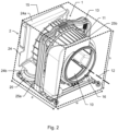
- Figs. 1 and 2 show an embodiment of a washer dryer comprising a laundry recipient 1 with a drum 10 arranged in a tub 11.
- Drum 10 is rotatable about an axis of rotation 12 by means of a rotation drive (not shown).
- Axis of rotation 12 is substantially horizontal.
- Laundry recipient 1 is suspended from a yoke 13, which rests on a base frame 14.
- the device comprises a cabinet 15, which is also mounted to frame 14.
- Cabinet 15 is substantially a cuboid having a width w, a height h, and a depth d ( Fig. 2 ).
- Figs. 3 and 4 show views of heat exchanging device 2 and laundry container 1.
- a water duct 41 connects heat exchanging device 2 to drum 10.
- Heat exchanging device 2 comprises a condenser 21 and an evaporator 22 of a heat pump 8.
- Heat pump 8 is schematically shown in Fig. 4 . It comprises a compressor 80 that feeds a heat pump medium to condenser 21, from where it passes an expansion valve 81 and enters evaporator 22. From evaporator 22, the fluid returns to compressor 80.
- the fluid condenses in condenser 21, thereby heating condenser 21 up, and it evaporates in evaporator 22, thereby cooling evaporator 22 down.
- a motor 82 is provided for operating pump 80.
- motor 82 and compressor 80 can be arranged in a foot section of the device.
- motor 82 and compressor 80 are vertically arranged. In a further advantageous embodiment, motor 82 can further be arranged horizontally beside the compressor 80. Such arrangement allows to exploit unused volume below heat exchanging device 2 and/or laundry recipient 1.
- Condenser 21 is arranged on top of evaporator 22.
- Heat exchanging device 2 comprises at least a first rinsing duct 31. In addition, there may be further rinsing ducts 32.
- Each rinsing duct 31, 32 extends in a substantially horizontal direction.
- the rinsing ducts 31, 32 are arranged, as shown, under a small angle to the horizontal direction, with said angle being e.g. larger than 1° and/or smaller than 10°.
- First rinsing duct 31 and, in the shown embodiment, the bottommost of the further rinsing ducts 32, are arranged adjacent to evaporator 22.
- the remaining further rinsing ducts 32 are arranged adjacent to condenser 21.
- a trough 4 is arranged adjacent to the lower end of the evaporator 22. It is configured to collect water from the heat exchanging device 2 and in particular from evaporator 22. The water might result from condensation in the evaporator 22 or from water that entered heat exchanging device 2 through the rinsing ducts 31, 32.
- a water duct 41 is connected to trough 4 and is configured to guide the collected water from trough 4 to laundry recipient 1, in particular to a bottom section of tub 11.
- water duct 41 can be connected to a drain pipe of the device.
- water duct 41 also serves to guide moisture-loaded air from the drum to evaporator 22.
- heat exchanging device 2 is arranged horizontally behind laundry recipient 1 and drum 10.
- Condenser 21 and evaporator 22 both have vertically arranged plates 201, 202 in order to increase the heat exchanging surface.
- condenser 21 comprises a smaller number of plates 201 than evaporator 22.
- Heat exchanging device 2 forms part of an air circulating system best explained in reference to Figs. 1 and 2 .
- the air circulating system comprises, apart from heat exchanging device 2, at least the following components:
- Ventilator 20 is advantageously arranged at the bottom of the device, i.e. in the lowest 25% of the device. This allows to exploit room that is available there. Also, this design allows to mount ventilator 20 on the bottom parts of the device, in particular on frame 14, which allows to reduce the amount of vibration and noise transmitted to cabinet 15.
- ventilator 20 is a radial ventilator with a substantially vertical axis of rotation, which allows to better exploit the room available at the bottom of the device.
- First air duct 24 has an input end 24a located at a top end of condenser 21. Further, it has an output end 24b located below evaporator 22 and connected to ventilator 20.
- Second air duct 25 is connected, at its input end 25a, to ventilator 20 at the bottom of the device. Its output end 25b is located at a level higher than the axis of rotation 12, in particular at a level higher than a maximum water level during washing the laundry. This prevents water from entering second air duct 25 from that end.
- the ducts 31, 32 are mounted directly to a housing 2a forming an air duct around evaporator 22 and condenser 21.
- the nozzles 300 are e.g. located at openings in housing 2a.
- the nozzles 300 are elongate slits or other openings arranged in the wall of each rinsing duct 31, 32.
- the nozzles may also be formed by separate elements from the rinsing ducts 31, 32 and be connected thereto.
- Fig. 7 shows a schematic of a laundry dryer, in particular washer-drier. This may e.g. be the device of Figs. 1 - 6 or any other similar device.
- the device comprises heat exchanging device 2 with condenser 21 and evaporator 22.
- Condenser 21 and evaporator 22 each can comprise the plates 201, 202.
- Trough 4 is arranged underneath heat exchanging device 2 to collect water therefrom.
- Heat exchanging device 2 is connected to ventilator 20.
- Ventilator 20 is configured to circulate air in the device.
- a control unit 9 is provided to control the components of the device. It is e.g. a microprocessor equipped with suitable software to carry out all operations of the methods described herein.
- control unit 9 controls ventilator 20 and therefore the transport of air through the air circulating system. It can also control the rotation of drum 10, the operation of heat pump 8, the feeding of water through the water ducts 31, 32, etc.
- control unit 9 activates heat pump 8 and ventilator 20. Further, drum 10 is rotated.
- evaporator 22 In evaporator 22, the air is cooled and loses moisture. Condensed water accumulates on the plates 202 and/or other parts of evaporator 22 and drops down into trough 4.
- this hot, dry air is designated as a1.
- the air a1 coming from heat exchanging device 2 enters drum 10 through front opening 16.
- drum 10 the heated and dry air a1 coming from the condenser 21 absorbs the water of the wet laundry, whereupon it is returned to evaporator 22.
- Control unit 9 can operate a drain pump to convey the water from the device.
- the lowest part of trough 4 is located at a higher level m1 than the lowest part of tub 11, which is at a level m2. This design allows to convey water from trough 4 to tub 11 by means of gravity.
- the device does not contain a fluff filter separate from heat exchanging device 2. Hence, fluff will accumulate in heat exchanging device 2 and in particular in evaporator 22.
- control unit 9 can feed water to one or more of the rinsing ducts 31, 32. When doing so, the water will leave the rinsing ducts 31, 32 through the nozzles 300 and enter the evaporator 22 and/or condenser 21 for washing the same.
- This rinsing water will enter trough 4 and water duct 41, where it is guided to tub 11 and/or to the drain pipe.
- Such a rinsing process can e.g. take place when required, e.g. before, during, or after drying laundry.
- the present device can be designed to not only dry laundry but also to wash it. In that case, process water for washing the laundry has to be fed to laundry recipient 1.
- At least part of said process water is fed to laundry recipient 1 and therefore drum 11 through the rinsing pipes 31, 32.
- This allows to re-use the rinsing water for rinsing the evaporator 22 and/or condenser 21 as process water in the washing process, thereby reducing the total water consumption.
- control unit 9 is adapted to first feed a first batch of water from the rinsing pipe(s) 31, 32 through the condenser 21 and/or evaporator 22 and to discard this first batch from the machine without it coming into contact with the laundry.
- control unit 9 can feed a second batch of water from the rinsing pipe(s) 31, 32 through the condenser 21 and/or evaporator 22 and to use this second batch for washing the laundry.
- This process is based on the understanding that the first batch of water will be heavily contaminated with lint. Hence, discarding it and not using it for washing reduces the amount of lint that comes into contact with the laundry.
- the user may select, depending on the type of laundry and the desired quality of the washing, if the first batch of rinsing water is to be discarded or not.
- washing proceeds basically as in a conventional machine.
- the bottom end of evaporator 22 is at a level m3 that is higher than a maximum level m4 of the process water in drum 10 while washing the laundry.
- Control unit 9 is adapted to keep the water level in drum 10 during washing below said maximum level m4. This design prevents washing water from flooding evaporator 22 and/or condenser 21.
- Fig. 8 shows a schematic of another advantageous laundry dryer.
- this embodiment comprises a lint filter 5 arranged in the path of the air a2 between laundry recipient 1 and evaporator 22.
- lint filter 5 To avoid lint filter 5 from coming into contact with water, it is, in this embodiment, not arranged in water duct 41. Rather, a separate air duct 51 is provided between laundry container 1 and evaporator 22, with laundry filter 5 arranged therein.
- water collected by trough 4 still flows through water duct 41 into tub 11.
- a siphon 6 is located in water duct 41.
- Control unit 9 is adapted to make sure that water is present in siphon 6 while drying. This water blocks water duct 41 for air.
- control unit 9 activates ventilator 20
- the wet air a2 from drum 10 passes through air duct 51 and filter 5 but not through water duct 41. Thus, it is filtered before entering heat exchanging device 2.
- the lowest part of lint filter 5 is advantageously arranged at a level m5 that is above maximum level m4 of the water in drum 10 and/or above the level m3 of the lower end of evaporator 22.
- the machine may comprise several rinsing ducts 31, 32, and control unit 9 can be adapted to individually and selectively feed water to said ducts.
- Control unit 9 is advantageously adapted to control the rinsing cycle in a sequence of first rinsing evaporator 22 and second rinsing condenser 21. This gives the condenser more time to cool before it is flushed with water, which avoids an excessive calcification of condenser 21.
- control unit 9 is adapted to only rinse the condenser 21 if it has a temperature below a threshold temperature T P , in particular with T P ⁇ 50°C.
- the rinsing water can, as mentioned, be collected by means of trough 4. It can be drained from trough 4 to drum 10 and be reused for the next washing cycle. Alternatively, part or all of it may be discarded and drained from the machine without using it for washing.
- control unit 9 can be adapted to rinse evaporator 22 and/or condenser 21 with water from the rinsing duct(s) 31 and/or 32 while turning on and off ventilator 20 in cycles. While ventilator 20 is running, air is pushed against the top-down-flow of the water into heat exchanging device 2 from below. This allows to keep at least part of the water in heat exchanging device 2, to be released once ventilator 20 is switched off. At that time, the trapped water will leave heat exchanging device 2 in a gush, which increases the cleaning efficiency of the process.
Landscapes
- Engineering & Computer Science (AREA)
- Textile Engineering (AREA)
- Detail Structures Of Washing Machines And Dryers (AREA)
Claims (18)
- Wäschetrockner, insbesondere ein Waschtrockner, umfassend- ein Gehäuse (15),- eine Trommel (10), die drehbar in dem Gehäuse (15) angeordnet ist und eine Öffnung (16) an einer Vorderseite zum Laden von Wäsche aufweist- eine Wärmepumpe mit einem Verflüssiger (21) und einem Verdampfer (22),- ein Luftzirkulationssystem, das die Trommel (10) mit dem Kondensator (21) und dem Verdampfer (22) verbindet, wobei das Luftzirkulationssystem einen Ventilator (20) umfasst, der so konfiguriert ist, dass er Luft in dem Luftzirkulationssystem (2) zwischen der Trommel (10) und dem Verdampfer (22) und dem Kondensator (21) zirkulieren lässt,- eine Steuereinheit (9),- zumindest ein Teil des Kondensators (21) und des Verdampfers (22) an einer Rückseite der Trommel (10) angeordnet sind, wobei die Rückseite von der Öffnung (16) weggerichtet ist,wobei der Kondensator (21) und der Verdampfer (22) jeweils, insbesondere vertikal ausgerichtete, Platten (201, 202) zum Wärmeaustausch zwischen Fluidleitungen der Wärmepumpe und Prozessluft des Umluftsystems aufweisen,dadurch gekennzeichnet, dass ein kürzester Abstand zwischen den einzelnen Platten (201) des Verflüssigers (21) grösser ist als ein kürzester Abstand zwischen den einzelnen Platten (202) des Verdampfers (22).
- Wäschetrockner nach Anspruch 1, der ein Waschtrockner ist und ferner einen Bottich (11) umfasst, wobei die Trommel (10) drehbar im Bottich (10) angeordnet ist.
- Wäschetrockner nach einem der vorhergehenden Ansprüche, wobei der Kondensator (21) vertikal über, insbesondere neben, zumindest einem Teil des Verdampfers (22) angeordnet ist.
- Wäschetrockner nach einem der vorangehenden Ansprüche, wobei sich der Kondensator (21) und/oder der Verdampfer (22) horizontal über mindestens 60 %, insbesondere mindestens 75 %, der gesamten Breite des Gehäuses (15) erstreckt.
- Wäschetrockner nach einem der vorhergehenden Ansprüche, wobei zumindest ein Abschnitt des Kondensators (21) und/oder des Verdampfers (22) horizontal hinter der Trommel angeordnet ist.
- Wäschetrockner nach einem der vorhergehenden Ansprüche, mit mindestens einem ersten Spülkanal (31), der benachbart zum Verdampfer (22) angeordnet ist, wobei der erste Spülkanal (31) eine Vielzahl von Düsen (200) aufweist oder mit diesen verbunden ist, die auf den Verdampfer (22) gerichtet sind.
- Wäschetrockner nach Anspruch 6, umfassend mindestens einen weiteren Spülkanal (32), wobei der weitere Spülkanal (32) eine Mehrzahl von auf den Kondensator (21) gerichteten Düsen (200) aufweist oder mit diesen verbunden ist,
und wobei insbesondere der weitere Spülkanal oberhalb des ersten Spülkanals (31) angeordnet ist. - Wäschetrockner nach Anspruch 7, wobei die Steuereinheit (9) dazu ausgestaltet ist, zuerst den Verdampfer (22) und anschliessend den Kondensator (21) zu spülen.
- Wäschetrockner nach Anspruch 7 oder 8, wobei die Steuereinheit (9) so ausgestaltet ist, dass sie den Kondensator (21) nur spült, wenn die Temperatur des Kondensators unter einer Schwellentemperatur TP liegt.
- Wäschetrockner nach einem der vorhergehenden Ansprüche mit einer unterhalb des Verdampfers (22) angeordneten Wasserwanne (4).
- Wäschetrockner nach Anspruch 10 mit einer Wasserleitung (41), die die Wasserwanne (4) mit einem Bottich (11) oder einem Ablaufrohr verbindet.
- Wäschetrockner nach einem der vorhergehenden Ansprüche, der ferner einen Flusenfilter (5) umfasst, der in dem Luftzirkulationssystem zwischen der Trommel (10) und dem Verdampfer (22) angeordnet ist.
- Wäschetrockner nach einem der Ansprüche 11 und 12, wobei die Wasserleitung (41) einen Siphon (6) umfasst.
- Wäschetrockner nach einem der Ansprüche 12 oder 13, bei dem der Flusenfilter (5) höher als ein unteres Ende des Verdampfers (22) angeordnet ist.
- Wäschetrockner nach einem der vorhergehenden Ansprüche 1 bis 11, ohne dass ein Flusensieb (5) im Luftumlaufsystem angeordnet ist.
- Wäschetrockner nach einem der vorhergehenden Ansprüche, wobei die Wärmepumpe (8) einen Kompressor (80) mit einem senkrecht oder waagerecht neben dem Kompressor (80) angeordneten Motor (82) aufweist.
- Wäschetrockner nach einem der vorhergehenden Ansprüche, wobei das Gehäuse (15) die maximalen Abmessungen von 60 cm Höhe, 60 cm Breite und 60 cm Tiefe aufweist.
- Wäschetrockner nach einem der vorhergehenden Ansprüche, bei dem der Ventilator (20) auf einem niedrigeren Niveau als der Verdampfer (22) angeordnet ist, wobei der Wäschetrockner ferner umfasst- einen ersten Luftkanal (24) mit einem Eingangsende (24a), das sich an einem oberen Ende des Kondensators (21) befindet, und einem Ausgangsende (24b), das sich unterhalb des Verdampfers (22) befindet und mit dem Ventilator (20) verbunden ist.- einen zweiten Luftkanal (25), der an einem Eingangsende (25a) mit dem Ventilator (20) verbunden ist und ein Ausgangsende (25b) aufweist, das höher als eine Drehachse (12) der Trommel (10) angeordnet ist, insbesondere auf einem Niveau, das höher als ein maximaler Wasserstand während des Waschens der Wäsche ist.
Applications Claiming Priority (1)
| Application Number | Priority Date | Filing Date | Title |
|---|---|---|---|
| PCT/EP2018/061831 WO2019214805A1 (en) | 2018-05-08 | 2018-05-08 | Laundry dryer |
Publications (2)
| Publication Number | Publication Date |
|---|---|
| EP3791016A1 EP3791016A1 (de) | 2021-03-17 |
| EP3791016B1 true EP3791016B1 (de) | 2025-06-25 |
Family
ID=62143159
Family Applications (1)
| Application Number | Title | Priority Date | Filing Date |
|---|---|---|---|
| EP18723480.2A Active EP3791016B1 (de) | 2018-05-08 | 2018-05-08 | Wäschetrockner |
Country Status (2)
| Country | Link |
|---|---|
| EP (1) | EP3791016B1 (de) |
| WO (1) | WO2019214805A1 (de) |
Families Citing this family (2)
| Publication number | Priority date | Publication date | Assignee | Title |
|---|---|---|---|---|
| WO2021164863A1 (en) * | 2020-02-19 | 2021-08-26 | V-Zug Ag | Dryer with self-cleaning program |
| CN115874426A (zh) * | 2022-10-10 | 2023-03-31 | 青州市坦博尔服饰股份有限公司 | 一种羽绒服脱水烘干装置 |
Citations (1)
| Publication number | Priority date | Publication date | Assignee | Title |
|---|---|---|---|---|
| EP3312334A1 (de) * | 2015-06-18 | 2018-04-25 | LG Electronics Inc. | Kleidungsbehandlungsvorrichtung mit trocknungsfunktion |
Family Cites Families (5)
| Publication number | Priority date | Publication date | Assignee | Title |
|---|---|---|---|---|
| ES2639179T3 (es) * | 2007-09-04 | 2017-10-25 | Lg Electronics Inc. | Aparato deshumidificador para secador |
| EP2471998B1 (de) * | 2011-01-04 | 2019-04-10 | Electrolux Home Products Corporation N.V. | Vorrichtung zum Wäschetrocknen |
| CN104593992A (zh) * | 2013-10-30 | 2015-05-06 | 海尔集团公司 | 一种波轮式热泵洗干一体机及烘干方法 |
| KR20160049848A (ko) * | 2014-10-28 | 2016-05-10 | 엘지전자 주식회사 | 의류처리장치 |
| WO2017174766A1 (en) * | 2016-04-08 | 2017-10-12 | Arcelik Anonim Sirketi | A heat pump laundry washing and/or drying machine |
-
2018
- 2018-05-08 WO PCT/EP2018/061831 patent/WO2019214805A1/en not_active Ceased
- 2018-05-08 EP EP18723480.2A patent/EP3791016B1/de active Active
Patent Citations (1)
| Publication number | Priority date | Publication date | Assignee | Title |
|---|---|---|---|---|
| EP3312334A1 (de) * | 2015-06-18 | 2018-04-25 | LG Electronics Inc. | Kleidungsbehandlungsvorrichtung mit trocknungsfunktion |
Also Published As
| Publication number | Publication date |
|---|---|
| EP3791016A1 (de) | 2021-03-17 |
| WO2019214805A1 (en) | 2019-11-14 |
Similar Documents
| Publication | Publication Date | Title |
|---|---|---|
| KR102343262B1 (ko) | 의류처리장치 | |
| RU2528354C2 (ru) | Электроприбор для сушки белья | |
| KR102300343B1 (ko) | 의류처리장치 | |
| JP6023976B2 (ja) | 衣類乾燥機 | |
| US9903067B2 (en) | Laundry machine | |
| JP6037500B2 (ja) | 洗濯乾燥機 | |
| EP1936022A1 (de) | Wäschetrockner | |
| EP2412861B1 (de) | Maschine zum Waschen und Trocknen von Wäsche | |
| JP7709774B2 (ja) | 洗濯機 | |
| JP2005304987A (ja) | 衣類乾燥装置 | |
| CN107109765A (zh) | 具有热交换器和冷凝物收集器的衣物处理设备 | |
| EP3791016B1 (de) | Wäschetrockner | |
| JP5948608B2 (ja) | 衣類乾燥機 | |
| KR101199392B1 (ko) | 건조기 | |
| JP6353005B2 (ja) | 洗濯乾燥機 | |
| KR102742785B1 (ko) | 의류 처리장치 및 이의 자동 세척운전 제어방법 | |
| JP2015054109A (ja) | 衣類乾燥機 | |
| WO2019214807A1 (en) | Method for operating a washer-dryer | |
| US12398501B2 (en) | Laundry appliance drainage | |
| CN103237936B (zh) | 用于清洁洗涤干燥机中的空气通道的方法以及适用所述方法的洗涤干燥机 | |
| CN117642537A (zh) | 衣物干燥机和洗衣机 | |
| CN103938422B (zh) | 衣物干燥机 | |
| JP2019068895A (ja) | 洗濯乾燥機 | |
| JP7561707B2 (ja) | 衣類乾燥機 | |
| JP4286847B2 (ja) | 洗濯乾燥機 |
Legal Events
| Date | Code | Title | Description |
|---|---|---|---|
| STAA | Information on the status of an ep patent application or granted ep patent |
Free format text: STATUS: UNKNOWN |
|
| STAA | Information on the status of an ep patent application or granted ep patent |
Free format text: STATUS: THE INTERNATIONAL PUBLICATION HAS BEEN MADE |
|
| PUAI | Public reference made under article 153(3) epc to a published international application that has entered the european phase |
Free format text: ORIGINAL CODE: 0009012 |
|
| STAA | Information on the status of an ep patent application or granted ep patent |
Free format text: STATUS: REQUEST FOR EXAMINATION WAS MADE |
|
| 17P | Request for examination filed |
Effective date: 20201008 |
|
| AK | Designated contracting states |
Kind code of ref document: A1 Designated state(s): AL AT BE BG CH CY CZ DE DK EE ES FI FR GB GR HR HU IE IS IT LI LT LU LV MC MK MT NL NO PL PT RO RS SE SI SK SM TR |
|
| AX | Request for extension of the european patent |
Extension state: BA ME |
|
| DAV | Request for validation of the european patent (deleted) | ||
| DAX | Request for extension of the european patent (deleted) | ||
| STAA | Information on the status of an ep patent application or granted ep patent |
Free format text: STATUS: EXAMINATION IS IN PROGRESS |
|
| 17Q | First examination report despatched |
Effective date: 20230809 |
|
| GRAP | Despatch of communication of intention to grant a patent |
Free format text: ORIGINAL CODE: EPIDOSNIGR1 |
|
| STAA | Information on the status of an ep patent application or granted ep patent |
Free format text: STATUS: GRANT OF PATENT IS INTENDED |
|
| INTG | Intention to grant announced |
Effective date: 20250310 |
|
| RIC1 | Information provided on ipc code assigned before grant |
Ipc: D06F 105/26 20200101ALN20250228BHEP Ipc: D06F 105/00 20200101ALN20250228BHEP Ipc: D06F 103/58 20200101ALN20250228BHEP Ipc: D06F 103/50 20200101ALN20250228BHEP Ipc: D06F 58/32 20200101ALN20250228BHEP Ipc: D06F 58/24 20060101ALN20250228BHEP Ipc: D06F 58/22 20060101ALN20250228BHEP Ipc: D06F 58/02 20060101ALN20250228BHEP Ipc: D06F 25/00 20060101ALN20250228BHEP Ipc: D06F 58/20 20060101AFI20250228BHEP |
|
| GRAS | Grant fee paid |
Free format text: ORIGINAL CODE: EPIDOSNIGR3 |
|
| GRAA | (expected) grant |
Free format text: ORIGINAL CODE: 0009210 |
|
| STAA | Information on the status of an ep patent application or granted ep patent |
Free format text: STATUS: THE PATENT HAS BEEN GRANTED |
|
| P01 | Opt-out of the competence of the unified patent court (upc) registered |
Free format text: CASE NUMBER: APP_20263/2025 Effective date: 20250429 |
|
| AK | Designated contracting states |
Kind code of ref document: B1 Designated state(s): AL AT BE BG CH CY CZ DE DK EE ES FI FR GB GR HR HU IE IS IT LI LT LU LV MC MK MT NL NO PL PT RO RS SE SI SK SM TR |
|
| REG | Reference to a national code |
Ref country code: GB Ref legal event code: FG4D |
|
| REG | Reference to a national code |
Ref country code: CH Ref legal event code: EP |
|
| REG | Reference to a national code |
Ref country code: CH Ref legal event code: EP |
|
| REG | Reference to a national code |
Ref country code: IE Ref legal event code: FG4D |
|
| REG | Reference to a national code |
Ref country code: DE Ref legal event code: R096 Ref document number: 602018082892 Country of ref document: DE |
|
| PG25 | Lapsed in a contracting state [announced via postgrant information from national office to epo] |
Ref country code: FI Free format text: LAPSE BECAUSE OF FAILURE TO SUBMIT A TRANSLATION OF THE DESCRIPTION OR TO PAY THE FEE WITHIN THE PRESCRIBED TIME-LIMIT Effective date: 20250625 |
|
| REG | Reference to a national code |
Ref country code: LT Ref legal event code: MG9D |
|
| PG25 | Lapsed in a contracting state [announced via postgrant information from national office to epo] |
Ref country code: NO Free format text: LAPSE BECAUSE OF FAILURE TO SUBMIT A TRANSLATION OF THE DESCRIPTION OR TO PAY THE FEE WITHIN THE PRESCRIBED TIME-LIMIT Effective date: 20250925 Ref country code: GR Free format text: LAPSE BECAUSE OF FAILURE TO SUBMIT A TRANSLATION OF THE DESCRIPTION OR TO PAY THE FEE WITHIN THE PRESCRIBED TIME-LIMIT Effective date: 20250926 |
|
| PG25 | Lapsed in a contracting state [announced via postgrant information from national office to epo] |
Ref country code: BG Free format text: LAPSE BECAUSE OF FAILURE TO SUBMIT A TRANSLATION OF THE DESCRIPTION OR TO PAY THE FEE WITHIN THE PRESCRIBED TIME-LIMIT Effective date: 20250625 |
|
| PG25 | Lapsed in a contracting state [announced via postgrant information from national office to epo] |
Ref country code: HR Free format text: LAPSE BECAUSE OF FAILURE TO SUBMIT A TRANSLATION OF THE DESCRIPTION OR TO PAY THE FEE WITHIN THE PRESCRIBED TIME-LIMIT Effective date: 20250625 |
|
| PG25 | Lapsed in a contracting state [announced via postgrant information from national office to epo] |
Ref country code: RS Free format text: LAPSE BECAUSE OF FAILURE TO SUBMIT A TRANSLATION OF THE DESCRIPTION OR TO PAY THE FEE WITHIN THE PRESCRIBED TIME-LIMIT Effective date: 20250925 |
|
| PG25 | Lapsed in a contracting state [announced via postgrant information from national office to epo] |
Ref country code: LV Free format text: LAPSE BECAUSE OF FAILURE TO SUBMIT A TRANSLATION OF THE DESCRIPTION OR TO PAY THE FEE WITHIN THE PRESCRIBED TIME-LIMIT Effective date: 20250625 |
|
| REG | Reference to a national code |
Ref country code: NL Ref legal event code: MP Effective date: 20250625 |
|
| PG25 | Lapsed in a contracting state [announced via postgrant information from national office to epo] |
Ref country code: NL Free format text: LAPSE BECAUSE OF FAILURE TO SUBMIT A TRANSLATION OF THE DESCRIPTION OR TO PAY THE FEE WITHIN THE PRESCRIBED TIME-LIMIT Effective date: 20250625 |
|
| PG25 | Lapsed in a contracting state [announced via postgrant information from national office to epo] |
Ref country code: PT Free format text: LAPSE BECAUSE OF FAILURE TO SUBMIT A TRANSLATION OF THE DESCRIPTION OR TO PAY THE FEE WITHIN THE PRESCRIBED TIME-LIMIT Effective date: 20251027 |
|
| REG | Reference to a national code |
Ref country code: AT Ref legal event code: MK05 Ref document number: 1806536 Country of ref document: AT Kind code of ref document: T Effective date: 20250625 |
|
| PG25 | Lapsed in a contracting state [announced via postgrant information from national office to epo] |
Ref country code: IS Free format text: LAPSE BECAUSE OF FAILURE TO SUBMIT A TRANSLATION OF THE DESCRIPTION OR TO PAY THE FEE WITHIN THE PRESCRIBED TIME-LIMIT Effective date: 20251025 |
|
| PG25 | Lapsed in a contracting state [announced via postgrant information from national office to epo] |
Ref country code: SM Free format text: LAPSE BECAUSE OF FAILURE TO SUBMIT A TRANSLATION OF THE DESCRIPTION OR TO PAY THE FEE WITHIN THE PRESCRIBED TIME-LIMIT Effective date: 20250625 Ref country code: AT Free format text: LAPSE BECAUSE OF FAILURE TO SUBMIT A TRANSLATION OF THE DESCRIPTION OR TO PAY THE FEE WITHIN THE PRESCRIBED TIME-LIMIT Effective date: 20250625 |
|
| PG25 | Lapsed in a contracting state [announced via postgrant information from national office to epo] |
Ref country code: CZ Free format text: LAPSE BECAUSE OF FAILURE TO SUBMIT A TRANSLATION OF THE DESCRIPTION OR TO PAY THE FEE WITHIN THE PRESCRIBED TIME-LIMIT Effective date: 20250625 |
|
| PG25 | Lapsed in a contracting state [announced via postgrant information from national office to epo] |
Ref country code: PL Free format text: LAPSE BECAUSE OF FAILURE TO SUBMIT A TRANSLATION OF THE DESCRIPTION OR TO PAY THE FEE WITHIN THE PRESCRIBED TIME-LIMIT Effective date: 20250625 |
|
| PG25 | Lapsed in a contracting state [announced via postgrant information from national office to epo] |
Ref country code: EE Free format text: LAPSE BECAUSE OF FAILURE TO SUBMIT A TRANSLATION OF THE DESCRIPTION OR TO PAY THE FEE WITHIN THE PRESCRIBED TIME-LIMIT Effective date: 20250625 |
|
| PG25 | Lapsed in a contracting state [announced via postgrant information from national office to epo] |
Ref country code: SK Free format text: LAPSE BECAUSE OF FAILURE TO SUBMIT A TRANSLATION OF THE DESCRIPTION OR TO PAY THE FEE WITHIN THE PRESCRIBED TIME-LIMIT Effective date: 20250625 |
|
| PG25 | Lapsed in a contracting state [announced via postgrant information from national office to epo] |
Ref country code: ES Free format text: LAPSE BECAUSE OF FAILURE TO SUBMIT A TRANSLATION OF THE DESCRIPTION OR TO PAY THE FEE WITHIN THE PRESCRIBED TIME-LIMIT Effective date: 20250625 |