EP3790733B1 - Method and machine for making flexible packages with side gussets - Google Patents
Method and machine for making flexible packages with side gussets Download PDFInfo
- Publication number
- EP3790733B1 EP3790733B1 EP19726513.5A EP19726513A EP3790733B1 EP 3790733 B1 EP3790733 B1 EP 3790733B1 EP 19726513 A EP19726513 A EP 19726513A EP 3790733 B1 EP3790733 B1 EP 3790733B1
- Authority
- EP
- European Patent Office
- Prior art keywords
- strip
- tubular element
- package
- along
- welding
- Prior art date
- Legal status (The legal status is an assumption and is not a legal conclusion. Google has not performed a legal analysis and makes no representation as to the accuracy of the status listed.)
- Active
Links
- 238000000034 method Methods 0.000 title claims description 54
- 238000003466 welding Methods 0.000 claims description 128
- 239000000463 material Substances 0.000 claims description 34
- 238000005520 cutting process Methods 0.000 claims description 21
- 238000011144 upstream manufacturing Methods 0.000 claims description 7
- 230000008569 process Effects 0.000 description 15
- 230000008878 coupling Effects 0.000 description 14
- 238000010168 coupling process Methods 0.000 description 14
- 238000005859 coupling reaction Methods 0.000 description 14
- 241001212149 Cathetus Species 0.000 description 5
- 235000013305 food Nutrition 0.000 description 5
- 230000008901 benefit Effects 0.000 description 3
- 230000015572 biosynthetic process Effects 0.000 description 3
- 238000004519 manufacturing process Methods 0.000 description 3
- 230000009977 dual effect Effects 0.000 description 2
- 238000003780 insertion Methods 0.000 description 2
- 230000037431 insertion Effects 0.000 description 2
- 238000012986 modification Methods 0.000 description 2
- 230000004048 modification Effects 0.000 description 2
- 238000007789 sealing Methods 0.000 description 2
- 230000002123 temporal effect Effects 0.000 description 2
- 239000002699 waste material Substances 0.000 description 2
- 241000282472 Canis lupus familiaris Species 0.000 description 1
- 241000282326 Felis catus Species 0.000 description 1
- 241001465754 Metazoa Species 0.000 description 1
- 238000005452 bending Methods 0.000 description 1
- 235000013351 cheese Nutrition 0.000 description 1
- 230000003247 decreasing effect Effects 0.000 description 1
- 239000012467 final product Substances 0.000 description 1
- 235000013312 flour Nutrition 0.000 description 1
- 238000005304 joining Methods 0.000 description 1
- 238000011017 operating method Methods 0.000 description 1
- 238000004806 packaging method and process Methods 0.000 description 1
- 239000000047 product Substances 0.000 description 1
- 230000009467 reduction Effects 0.000 description 1
- 230000000284 resting effect Effects 0.000 description 1
- 238000000926 separation method Methods 0.000 description 1
- 238000005728 strengthening Methods 0.000 description 1
- 230000007704 transition Effects 0.000 description 1
- 238000013519 translation Methods 0.000 description 1
Images


Classifications
-
- B—PERFORMING OPERATIONS; TRANSPORTING
- B31—MAKING ARTICLES OF PAPER, CARDBOARD OR MATERIAL WORKED IN A MANNER ANALOGOUS TO PAPER; WORKING PAPER, CARDBOARD OR MATERIAL WORKED IN A MANNER ANALOGOUS TO PAPER
- B31B—MAKING CONTAINERS OF PAPER, CARDBOARD OR MATERIAL WORKED IN A MANNER ANALOGOUS TO PAPER
- B31B70/00—Making flexible containers, e.g. envelopes or bags
- B31B70/60—Uniting opposed surfaces or edges; Taping
- B31B70/64—Uniting opposed surfaces or edges; Taping by applying heat or pressure
- B31B70/645—Making seals transversally to the direction of movement
-
- B—PERFORMING OPERATIONS; TRANSPORTING
- B31—MAKING ARTICLES OF PAPER, CARDBOARD OR MATERIAL WORKED IN A MANNER ANALOGOUS TO PAPER; WORKING PAPER, CARDBOARD OR MATERIAL WORKED IN A MANNER ANALOGOUS TO PAPER
- B31B—MAKING CONTAINERS OF PAPER, CARDBOARD OR MATERIAL WORKED IN A MANNER ANALOGOUS TO PAPER
- B31B70/00—Making flexible containers, e.g. envelopes or bags
- B31B70/005—Making flexible containers, e.g. envelopes or bags involving a particular layout of the machinery or relative arrangement of its subunits
-
- B—PERFORMING OPERATIONS; TRANSPORTING
- B65—CONVEYING; PACKING; STORING; HANDLING THIN OR FILAMENTARY MATERIAL
- B65D—CONTAINERS FOR STORAGE OR TRANSPORT OF ARTICLES OR MATERIALS, e.g. BAGS, BARRELS, BOTTLES, BOXES, CANS, CARTONS, CRATES, DRUMS, JARS, TANKS, HOPPERS, FORWARDING CONTAINERS; ACCESSORIES, CLOSURES, OR FITTINGS THEREFOR; PACKAGING ELEMENTS; PACKAGES
- B65D31/00—Bags or like containers made of paper and having structural provision for thickness of contents
- B65D31/10—Bags or like containers made of paper and having structural provision for thickness of contents with gusseted sides
-
- B—PERFORMING OPERATIONS; TRANSPORTING
- B31—MAKING ARTICLES OF PAPER, CARDBOARD OR MATERIAL WORKED IN A MANNER ANALOGOUS TO PAPER; WORKING PAPER, CARDBOARD OR MATERIAL WORKED IN A MANNER ANALOGOUS TO PAPER
- B31B—MAKING CONTAINERS OF PAPER, CARDBOARD OR MATERIAL WORKED IN A MANNER ANALOGOUS TO PAPER
- B31B2100/00—Rigid or semi-rigid containers made by folding single-piece sheets, blanks or webs
-
- B—PERFORMING OPERATIONS; TRANSPORTING
- B31—MAKING ARTICLES OF PAPER, CARDBOARD OR MATERIAL WORKED IN A MANNER ANALOGOUS TO PAPER; WORKING PAPER, CARDBOARD OR MATERIAL WORKED IN A MANNER ANALOGOUS TO PAPER
- B31B—MAKING CONTAINERS OF PAPER, CARDBOARD OR MATERIAL WORKED IN A MANNER ANALOGOUS TO PAPER
- B31B2155/00—Flexible containers made from webs
- B31B2155/001—Flexible containers made from webs by folding webs longitudinally
- B31B2155/0014—Flexible containers made from webs by folding webs longitudinally having their openings facing transversally to the direction of movement
-
- B—PERFORMING OPERATIONS; TRANSPORTING
- B31—MAKING ARTICLES OF PAPER, CARDBOARD OR MATERIAL WORKED IN A MANNER ANALOGOUS TO PAPER; WORKING PAPER, CARDBOARD OR MATERIAL WORKED IN A MANNER ANALOGOUS TO PAPER
- B31B—MAKING CONTAINERS OF PAPER, CARDBOARD OR MATERIAL WORKED IN A MANNER ANALOGOUS TO PAPER
- B31B2155/00—Flexible containers made from webs
- B31B2155/002—Flexible containers made from webs by joining superimposed webs, e.g. with separate bottom webs
-
- B—PERFORMING OPERATIONS; TRANSPORTING
- B31—MAKING ARTICLES OF PAPER, CARDBOARD OR MATERIAL WORKED IN A MANNER ANALOGOUS TO PAPER; WORKING PAPER, CARDBOARD OR MATERIAL WORKED IN A MANNER ANALOGOUS TO PAPER
- B31B—MAKING CONTAINERS OF PAPER, CARDBOARD OR MATERIAL WORKED IN A MANNER ANALOGOUS TO PAPER
- B31B2160/00—Shape of flexible containers
- B31B2160/20—Shape of flexible containers with structural provision for thickness of contents
-
- B—PERFORMING OPERATIONS; TRANSPORTING
- B31—MAKING ARTICLES OF PAPER, CARDBOARD OR MATERIAL WORKED IN A MANNER ANALOGOUS TO PAPER; WORKING PAPER, CARDBOARD OR MATERIAL WORKED IN A MANNER ANALOGOUS TO PAPER
- B31B—MAKING CONTAINERS OF PAPER, CARDBOARD OR MATERIAL WORKED IN A MANNER ANALOGOUS TO PAPER
- B31B70/00—Making flexible containers, e.g. envelopes or bags
- B31B70/14—Cutting, e.g. perforating, punching, slitting or trimming
- B31B70/16—Cutting webs
- B31B70/18—Cutting webs longitudinally
-
- B—PERFORMING OPERATIONS; TRANSPORTING
- B31—MAKING ARTICLES OF PAPER, CARDBOARD OR MATERIAL WORKED IN A MANNER ANALOGOUS TO PAPER; WORKING PAPER, CARDBOARD OR MATERIAL WORKED IN A MANNER ANALOGOUS TO PAPER
- B31B—MAKING CONTAINERS OF PAPER, CARDBOARD OR MATERIAL WORKED IN A MANNER ANALOGOUS TO PAPER
- B31B70/00—Making flexible containers, e.g. envelopes or bags
- B31B70/26—Folding sheets, blanks or webs
- B31B70/262—Folding sheets, blanks or webs involving longitudinally folding, i.e. along a line parallel to the direction of movement
-
- B—PERFORMING OPERATIONS; TRANSPORTING
- B31—MAKING ARTICLES OF PAPER, CARDBOARD OR MATERIAL WORKED IN A MANNER ANALOGOUS TO PAPER; WORKING PAPER, CARDBOARD OR MATERIAL WORKED IN A MANNER ANALOGOUS TO PAPER
- B31B—MAKING CONTAINERS OF PAPER, CARDBOARD OR MATERIAL WORKED IN A MANNER ANALOGOUS TO PAPER
- B31B70/00—Making flexible containers, e.g. envelopes or bags
- B31B70/26—Folding sheets, blanks or webs
- B31B70/36—Folding sheets, blanks or webs by continuously feeding them to stationary members, e.g. plates, ploughs or cores
-
- B—PERFORMING OPERATIONS; TRANSPORTING
- B31—MAKING ARTICLES OF PAPER, CARDBOARD OR MATERIAL WORKED IN A MANNER ANALOGOUS TO PAPER; WORKING PAPER, CARDBOARD OR MATERIAL WORKED IN A MANNER ANALOGOUS TO PAPER
- B31B—MAKING CONTAINERS OF PAPER, CARDBOARD OR MATERIAL WORKED IN A MANNER ANALOGOUS TO PAPER
- B31B70/00—Making flexible containers, e.g. envelopes or bags
- B31B70/60—Uniting opposed surfaces or edges; Taping
- B31B70/64—Uniting opposed surfaces or edges; Taping by applying heat or pressure
- B31B70/642—Uniting opposed surfaces or edges; Taping by applying heat or pressure using sealing jaws or sealing dies
-
- B—PERFORMING OPERATIONS; TRANSPORTING
- B31—MAKING ARTICLES OF PAPER, CARDBOARD OR MATERIAL WORKED IN A MANNER ANALOGOUS TO PAPER; WORKING PAPER, CARDBOARD OR MATERIAL WORKED IN A MANNER ANALOGOUS TO PAPER
- B31B—MAKING CONTAINERS OF PAPER, CARDBOARD OR MATERIAL WORKED IN A MANNER ANALOGOUS TO PAPER
- B31B70/00—Making flexible containers, e.g. envelopes or bags
- B31B70/74—Auxiliary operations
- B31B70/81—Forming or attaching accessories, e.g. opening devices, closures or tear strings
- B31B70/813—Applying closures
- B31B70/8131—Making bags having interengaging closure elements
- B31B70/8132—Applying the closure elements in the machine direction
Definitions
- the present invention relates to the field of sealable packages. More specifically, the present invention relates to the field of sealable packages made of flexible material having side gussets, which preferably further have reclosable openings. Moreover, the present invention relates to the field of machines for making sealable packages and a method for making such packages.
- Packages made of flexible material are commonly used in various fields: from the food to the industrial field.
- Packages made of flexible material for example, are commonly used to contain flour, grated cheese or the like, or alternatively for storing animal food, such as kibble for dogs or for cats.
- Such packages have various sizes according to the use made of such packages. In the case of pet food for example, such packages have also very large sizes to allow storing an increased quantity of food.
- such packages are provided with side gussets which allow the package to extend in depth so as to allow a significant increase of the inner volume.
- Such side gussets normally are an accordion structure, which most times is a simple sheet made of flexible material folded in half and placed at opposite ends of the front panel and of the back panel of the package so as to connect the front panel to the back panel.
- PTL1 shows a method for making such packages.
- Figure 13 of PTL1 shows that the tubular element 1, from which right and left side gussets of two successive packages are made, is conveyed between two layers of strip 2 which form the front panel and the back panel of the final package.
- tubular element 1 first is secured to the strips 2 by means of three seal spots 24 and then the two end portions of the tubular element are folded, at which slits 17 are positioned that allow the passage of the air.
- PTL1 clearly shows the formation of an open, and therefore not sealable, package that allows the passage of air from the outside to the inside of the package by means of the slits 17.
- the folding is ensured by the folding means 22 and 25 which, by means of the cooperation thereof, allow having an end portion of the tubular element 1 having a pointed shape.
- Such pointed portion is formed by two right-angled triangles placed adjacent to each other. After such folding, the folding is secured by means of a forth seal spot 24.
- a first disadvantage is that the author of PTL1 has positioned the tubular element 1 between two strips 2 that are completely free to move with respect to each other. If on the one hand this solution might seem advantageous because it allows having more space to position the various sealers and the folding means between the two strips, on the other it implies a significant slowing down of the package forming process because an increased number of operations at the same point in space are to be performed for such purpose on the strips 2 and on the tubular element 1 before conveying the strip 2 towards a successive sub-station.
- a second disadvantage is that there is an increased difficulty in achieving an increased accuracy in positioning the tubular element 1 with respect to the strips 2 in the system described in PTL1. This is because the increased number of components present therein and the simultaneous increased degree of freedom of the various components results in an increased level of difficulty in positioning the tubular element at a more accurate point of the strips 2 with a given accuracy.
- US 2001/053253 A1 relates to a method and a machine for making flexible packages wherein a first strip of flexible material is secured to a second strip of flexible material by means of a welding surface, the first and second strip being positioned on top of each other and being moved in a conveying direction.
- Said welding surface extends in a direction perpendicular to said conveying direction and is positioned at a first side edge of said first and of said second strip.
- the flexible packages do not comprise side gussets.
- US 2004/258332 A1 discloses a method and a machine for making flexible packages wherein tubular elements which will form side gussets are conveyed between a first and a second strip which strips are completely spaced apart from each other.
- the present invention is based on the idea of making a welding surface that allows pre-securing the two strips so that the first strip and the second strip can be partially moved with respect to each other in the successive stations without however them being completely moved with respect to one another because they are already pre-secured.
- a method for making packages comprising the following steps:
- This solution is particularly advantageous because it allows pre-securing the two strips before the tubular element is introduced between the two strips. Indeed, having defined that the extension of the welding surface is less than the width of each of the first and the second strip clearly implies that such welding surface does not correspond to the one made for the actual closure of the package, rather corresponds to a pre-securing configured so as to pre-secure the two strips. Therefore, this pre-securing is particularly advantageous because it allows securing the two strips upstream and leaving free a portion of the strips for introducing the tubular element that forms the side gussets of the package.
- this solution is particularly advantageous because it allows both allowing an increased accuracy in the successive positioning of the tubular element and reducing the number of operations to be performed in the coupling station, while at the same time ensuring a sufficient space for introducing the tubular element.
- due to such welding surface it is possible to position the side gussets at a predetermined distance from the first side edge of the strips so as to have an upper portion of the final package free from gussets, thus allowing to apply a reclosable opening at such portion.
- the two strips have the same width, it is possible to position the side edges of the two strips at each other so as to use such side edges of the strips as upper and lower edge of the final package.
- a method for making packages wherein a distance between two midpoints of two of the welding surfaces that are positioned consecutively along the conveying direction is equal to the width of the package, wherein the distance is measured along the conveying direction.
- a method for making packages wherein an edge of the welding surface is positioned along the first side edge of the first and the second strip.
- This solution is particularly advantageous because it allows positioning such welding surface along an edge of the strips and leaving free the opposite edge so as to convey for example, the tubular element that serves to make the gussets at the other side edge of the strips.
- a method for making packages wherein the first length, along which the welding surface extends, is less than half the width of the first strip and the second strip, the first length preferably being comprised between 35 mm and 50 mm, more preferably the length is equal to 50 mm.
- the first length preferably being comprised between 35 mm and 50 mm, more preferably the length is equal to 50 mm.
- Such solution is particularly advantageous because it allows having an upper portion of the final package free from gussets wherein such portion is less than half the axial extension of the package.
- the above-indicated preferable range wherein the first length is comprised allows having an upper portion free from gussets equal to at least 35 mm. This contrivance allows for example, installing a reclosable opening at this area.
- a method for making packages wherein during step a), the first and the second strip are made from a third strip coming from reel, wherein the first and the second strip preferably are obtained by folding the third strip coming from reel along a fold line coinciding with the axis of the third strip so as to arrange the side edges of the third strip at one another and by cutting the third strip along such fold line.
- This solution is particularly advantageous because it allows having a single reel from which the two strips are obtained. This implies for example, being able to effectively reduce the sizes of the machine and replacing one reel alone, if it is used up.
- the term axis of the third strip here means the axis along which the third strip is unrolled and passing through the midpoint of the third strip.
- a method for making packages wherein the method further comprises the following step: d) providing a reclosable opening between the first strip and the second strip so as to position the reclosable opening, along a direction parallel to the conveying direction, at a distance from the first edge that is less than the first length so as to secure the reclosable opening between the first strip and the second strip by means of the welding surface.
- reclosable opening is conveyed along a direction parallel to the one of the strips so as to effectively position such opening parallel to the upper edge of the package.
- reclosable opening preferably is provided from reel so as to be provided in continuous manner.
- reclosable opening preferably is a reclosable zipper length that is secured both to the front strip and to the back strip so as to secure a portion to each of the strips and thereby to ensure a closure of the final package. Indeed, by engaging the first portion of the reclosable opening with the second portion of the reclosable opening, it is possible to close the upper opening of the package after the package itself was opened the first time.
- a method for making packages wherein after the first strip is secured to the second strip by means of the welding surface, a second side edge of the first strip and a second side edge of the second strip, which are opposite to the first side edge, are moved away from each other so as to form an empty space between the first strip and the second strip, wherein the empty space extends from the second edge to the welding surface.
- This solution is particularly advantageous because it allows opening the first strip from the second strip without there being the risk for the two strips to move laterally with respect to each other because they were pre-secured as mentioned above, by the welding surface. Therefore, this opening allows moving the first strip away from the second strip along a side edge and therefore, conveying the tubular element that forms the side gussets of the package by means of such opening.
- the method further comprises the following step: c) conveying a tubular element that forms side gussets of the package into the empty space until an end portion of the tubular element reaches a first distance from the first side edge, wherein the first distance is greater than or equal to the first length; wherein the tubular element preferably is conveyed along a direction perpendicular to the conveying direction of the first and the second strip.
- This solution is particularly advantageous because it allows using the space formed between the two strips to introduce the tubular element itself, which as mentioned, forms the side gussets of the package.
- this solution allows uncoupling the point wherein the welding of the welding surface occurs and the point wherein the tubular element is inserted, due to the provision of the above-described welding surface.
- the fact that the first distance is greater than or equal to the first length allows positioning the tubular element at the bottom with respect to the welding surface, thus allowing to have a package having an upper portion free from gussets.
- a method for making packages wherein the tubular element is made by folding a sheet made of flexible material along two mutually parallel first fold lines so as to form the tubular element, and by folding an end portion of the tubular element along two second fold lines that are oblique with respect to the direction of the two first fold lines so as to form an end portion of the tubular element that has two triangular portions having two mutually parallel sides.
- This solution is particularly advantageous because it allows obtaining side gussets having an inclined surface.
- this solution allows providing such empty space with an already “ready" tubular element without the need to perform the various folding operations in such empty space. This therefore allows significantly reducing the time for producing the packages.
- a method for making packages wherein, after the tubular element is conveyed into the empty space between the first strip and the second strip, the tubular element is secured to the first strip and to the second strip by means of a second welding surface.
- a method for making packages wherein the packages are sealable packages.
- the package allows sealing the atmosphere inside the package with respect to the atmosphere outside the package, for example by allowing the organoleptic properties of the material contained in the package to be kept.
- a machine for making packages made of flexible material comprises a preparing station configured so as to provide a first strip and a second strip positioned on top of each other along a conveying direction; wherein the preparing station comprises first welding means configured so as to make a welding surface which extends in a direction perpendicular to the conveying direction of the first and the second strip for a first length which is less than the width of each of the first and the second strip; the welding surface is positioned at a first side edge of the first and the second strip.
- this pre-securing is particularly advantageous because it allows securing the two strips upstream and leaving free a portion for introducing the tubular element that forms the side gussets of the package.
- this solution is particularly advantageous because it allows both allowing an increased accuracy in the successive positioning of the tubular element and reducing the number of operations to be performed in the coupling station, while at the same time ensuring a sufficient space for introducing the tubular element.
- a machine for making packages made of flexible material wherein the first length is less than half the width of the first strip and the second strip, the first length preferably being comprised between 35 mm and 50 mm, more preferably the length is equal to 50 mm.
- the first length is less than half the width of the first strip and the second strip, the first length preferably being comprised between 35 mm and 50 mm, more preferably the length is equal to 50 mm.
- Such solution is particularly advantageous because it allows having an upper portion of the final package free from gussets wherein such portion is less than half the axial extension of the package.
- the above-indicated preferable range wherein the first length is comprised allows having an upper portion free from gussets equal to at least 35 mm. This contrivance allows for example, installing a reclosable opening at this area.
- a machine for making packages made of flexible material wherein the preparing station further comprises folding means configured so as to fold a third strip coming from reel along a fold line that coincides with the axis of the third strip so as to arrange the side edges of the third strip one at the other, and cutting means configured so as to cut a third strip along the fold line so as to allow obtaining the first and the second strip.
- folding means configured so as to fold a third strip coming from reel along a fold line that coincides with the axis of the third strip so as to arrange the side edges of the third strip one at the other
- cutting means configured so as to cut a third strip along the fold line so as to allow obtaining the first and the second strip.
- a machine for making packages made of flexible material wherein the preparing station further comprises second welding means configured so as to seal a reclosable opening at the first and the second strip, the second welding means being positioned at the first edge along a direction parallel to the conveying direction.
- This solution is particularly advantageous because it allows welding the reclosable opening to each of the two strips along the direction wherein the reclosable opening extends.
- reclosable opening preferably is provided from reel so as to be provided in continuous manner.
- Such reclosable opening preferably is a reclosable zipper length that is secured both to the front strip and to the back strip so as to secure a portion to each of the strips and thereby to ensure a closure of the final package. Indeed, by engaging the first portion of the reclosable opening with the second portion of the reclosable opening, it is possible to close the upper opening of the package after the package itself was opened the first time.
- a machine for making packages made of flexible material wherein the welding surface allows securing the reclosable opening in a side area of the package.
- This solution is particularly advantageous because it allows effectively taking advantage of the welding surface that as mentioned, allowed pre-securing the two strips also to secure the reclosable opening between the first strip and the second strip, thus serving a dual purpose.
- the reclosable opening is conveyed along a direction parallel to the one of the strips so as to effectively position such opening parallel to the upper edge of the package.
- this solution also allows flattening a side portion of the reclosable opening, therefore decreasing the thickness resulting therefrom.
- a machine for making packages made of flexible material wherein the second welding means are positioned upstream of the first welding means.
- This solution is particularly advantageous because it allows inserting an element, such as a contrast element, between the two welding means so as to allow the continuous opening of the reclosable opening after it is coupled to the front and back strip.
- the plane on which the sealable package 100 rests is a plane which is at the opposite side with respect to the one wherein the opening of the package is positioned. Therefore, the term “top” means a portion of the package placed at the opening of the package, through which the contents of the package may be inserted.
- right refers to the right side of the reader and similarly, left refers to the left side of the reader; finally, front is the portion of package facing the side of the reader and similarly, back refers to the opposite side with respect to the reader.
- conveying direction in the present invention means a direction along which the package 100, or parts thereof, is made.
- conveying direction in the present invention means a direction along which the package 100, or parts thereof, is made.
- one process is performed “downstream” with respect to another, it means that during the process leading to making the package 100, such process is performed after another process was performed.
- one process is performed "upstream” with respect to another, it means that during the process leading to making the package 100, a process is performed before another process was performed.
- Figure 1 diagrammatically illustrates a sealable package 100 according to an embodiment of the present invention.
- Figure 1 shows a front view of the package 100; in particular, the upper opening 5 of the package is positioned at an upper end of the drawing, while the lower edge 12 of the package 100 is positioned in the lower part of the drawing.
- the package 100 is sealable because, as will be apparent from the following description, after filling the package 100 through the upper opening 5 and having made, at such opening 5, a welding surface adapted to close the opening of the package, it will be impossible for the atmosphere outside the package to enter the package. Therefore, the environment inside the package 100 will be completely isolated with respect to the external environment of the package 100.
- the sealable package 100 made of flexible material comprises a front panel 1 and a back panel 2.
- the front panel 1 and the back panel 2 are connected by two side gussets: a right side gusset 3 and a left side gusset 4.
- Such side gussets 3, 4 are provided at opposite ends of the front panel 1 and of the back panel 2.
- the two side gussets 3, 4 comprise a sheet folded along a fold line L1 that is parallel to the axis Ax1 of the package. In this manner, an accordion structure is formed which allows increasing the distance between the front panel 1 and the back panel 2.
- the side gussets 3, 4 to comprise more than one fold line so as to significantly increase the distance between the two panels, and therefore significantly increase the volume of the package.
- the front panel 1, the back panel 2 and the two side gussets 3, 4 preferably are made of sheets made of flexible and sealable material. Such sheets preferably are sealable only on one of the two surfaces.
- the front panel 1 and the back panel 2 have the sealable surfaces facing the inside of the package 100.
- the side gussets 3 and 4 have sealable surfaces facing the inside of the package 100.
- the side gussets 3, 4 have sealable surfaces facing the front panel 1 and the back panel 2 so as to allow a seal between the side gussets 3, 4 and the front and back panels 1, 2, so as to allow a side closure of the package 100 to be ensured.
- the package has a reclosable opening 15 positioned at an area close to the opening 5 of the package 100.
- Such reclosable opening 15 preferably extends along a direction perpendicular to the axis Ax1 of the package 100.
- the reclosable opening is comprised between the side welding surfaces 22, 23.
- An example of reclosable opening is given by a zipper which allows reversibly opening and closing such package 100.
- the reclosable opening 15 therefore extends between the front panel 1 and the back panel 2: a first portion of the reclosable opening 15 is installed on the inner surface of the front panel 1 of the package 100, while a second portion of the reclosable opening 15 is installed on the inner surface of the back panel 2 of the package 100. In this manner, the first portion can be engaged with the second portion so as to ensure the closure of the package 100 also after the package 100 has been opened for the first time.
- An upper end portion of the side gussets 3 and 4 is folded along a fold line L2 which is inclined with respect to the axis Ax1 of the package 100.
- the portion folded along the fold line L2 therefore is an end portion of each side gusset 3, 4 which is in the vicinity of the opening 5 of the package 100.
- triangular portions 6 and 7 of the side gussets 3 and 4 results from folding the end portion of the side gussets 3,4, and therefore the possibility of having an upper portion of the package 100 free from gussets. This allows positioning the reclosable opening 15 in the area where there are only two layers of material (area having two thicknesses): the layer of the front panel 1 and the layer of the back panel 2.
- the triangular portions 6, 7 have the shape of a right-angled triangle having a hypotenuse that is inclined with respect to the axis Ax1 of the package and wherein the vertex of each triangular portion 6, 7, which is higher in the package 100, is positioned in a side area of the package at which the seal is made (which is further explained later), which allows joining the front panel 1 to the back one 2 with the side gussets 3, 4 comprised therebetween.
- Each of the two triangular portions 6, 7 therefore has a cathetus 8, 9 parallel to the outer edge 10, 11 of the package and another cathetus 13, 14 perpendicular to the outer edge 10, 11 of the package 100.
- each cathetus 8, 9 parallel to the outer edge 10, 11 of the package is positioned at a predetermined distance D1 from the outer edge of the package.
- this allows welding the front panel 1 to the gussets 3, 4 and then to the back panel 2, therefore “trapping" each triangular portion 6, 7. This therefore allows ensuring an effective sealing of the environment inside the package with respect to the external environment.
- side seals 22, 23 are made at the right 10 and left 11 side edges of the package, said seals allowing to close the package 100 along the right side and the left side.
- Such seals 22, 23 extend along the whole height h3 of the package. The width of such seals is greater than the above-described predetermined distance D1.
- the width of the welding surface 22 and 23 is greater than the first predetermined distance D1 so as to allow "trapping" the triangular portion between the front panel 1 and the back panel 2.
- predetermined distance D1 may preferably be greater than or equal to 1 mm, and in certain cases, also have larger sizes.
- the distance D1 preferably is greater than or equal to 4 mm. It is apparent that such distance strongly depends on the sizes of the package. For example, smaller packages have a smaller distance D1. Vice versa, larger packages have a larger distance D1.
- the distance D1 depends on the width of the side welding surfaces 22 and 23. To this end, the wider such surfaces, the greater the distance D1.
- a lower welding surface 27 adapted to close the bottom of the package 100 so as to prevent the material contained in the package to come out from the bottom, is positioned along the lower edge 12 of the package 100. Furthermore, there are two welding surfaces 25 and 26 that are inclined with respect both to the welding surface 22 and 23 and to the welding surface 27 to allow effectively emptying the package and at the same time strengthening the lower edges. The effective emptying is due to the fact that the welding surfaces 25 and 26 allow having a bottom of the package that is flat, and therefore easier to empty.
- This contrivance allows the material contained in the package 100 to effectively exit, which otherwise could be trapped at the lower corners of the package 100. Indeed, it is the object of the welding surfaces 25 and 26 to also reduce the possibility of part of the contents of the package to remain trapped at the lower edges.
- the side gussets 3 and 4 are positioned at a predetermined distance D2 with respect to the lower edge 12 of the package 100. This is due to the fact that in this manner, the lower portion of the gussets may be "trapped" between the front panel 1 and the back panel 2.
- distance D2 may vary according to the size of the package 100. As an indicative value, such distance preferably is greater than or equal to 1 mm. Moreover, most of the time such distance preferably is less than 5 mm.
- Packages like the ones shown in figure 1 may have a wide range of sizes. For example, they may have a size that varies from relatively small packages, configured so as to contain 0.1 kg of material, to much larger packages, that allow containing up to 20 kg of material.
- the right side gusset 3 and the left side gusset 4 extend along the side edge 10, 11, of the package up to a height h1 from the lower edge 12 of the package 100. Therefore as shown in the drawing, the height h3 of the package 100 is equal to the sum of the distance h2 of the upper end portion of the gussets 3, 4 up to the upper edge 5, with the distance h1.
- Such gussets 3, 4 are positioned at the predetermined distance D2 with respect to the lower edge 12 of the package 100 which therefore is represented by the lower edge of the front panel 1 and of the back panel 2.
- the upper end portion of the right 3 and left 4 side gusset is positioned at a distance h2 of the opening 5 of the package 100. This allows having an inner portion of the package 100 free from gussets and therefore also an effective exit of the material contained in the package 100.
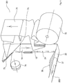
- Figure 2 shows a machine 200 according to an embodiment of the present invention.
- the machine 200 shown in the drawing comprises four stations.
- a first station 201 is configured so as to prepare a strip of material which is then coupled in station 202 with the tubular element coming from the station 203.
- the station 203 is then configured so as to form the side gussets 2 and 3 of the package 100, which are shown in figure 1 .
- Downstream of the coupling station 202 there is positioned a packaging station 204 wherein the package produced in the coupling station 202 is opened, filled with the contents of the package and finally closed at the opening 5 of the package 100 so as to seal the environment inside the package with respect to the external environment.
- the preparing station 201 which is a vertical station in the particular example depicted in the drawing, the coupling station 202 and the tubular element forming station 203, are described in detail.
- the method for making the package 100 will be apparent from the description of the various stations of the machine 200 and of how such stations contribute to making the package 100.
- the preparing station 201 comprises a reel 72 on which a sheet 70 made of flexible material is wound, which as mentioned above, is sealable on one of the two sides.
- the sheet 70 is unrolled from the reel 72 and conducted towards a forming device 73 which allows bending the sheet in half so as to form a folded sheet having a width equal to half the width that the sheet 70 had when it was positioned on the reel 72.
- the sheet 70 is unrolled from the reel 72 and conveyed along the conveying direction indicated by the arrow in figure 3 towards the forming device 73, where it is folded.
- a blade 71 is positioned immediately downstream of the forming device 73, which blade allows cutting the sheet 70, therefore dividing it into two equal parts along the fold line that was provided by the forming device 73.
- the sheets 19, 20 have the sealable surfaces facing each other while the outer surfaces are not sealable, thus allowing the two sheets to be sealed to each other.
- a reel 74 is placed downstream of the blade 71, on which reel a zipper length 15 is wound, which may be used as reclosable opening of the package 100.
- the zipper length 15 is unrolled from the reel 74 and coupled to both sheets 19, 20 produced downstream of the blade 71.
- the zipper length 15 is coupled to the front sheet 19 and the back sheet 20 by means of welding bars 42 which allow welding the reclosable opening 15 to what will be the panels 1, 2 of the package 100.
- the reclosable zipper 15 is provided from reel 74 and is coupled both with the front sheet and with the back sheet by means of the seal provided by the welding bars 42.
- the reclosable opening 15 is opened, that is after a first portion of the reclosable opening 15 is uncoupled from a second portion of the reclosable opening 15, the first portion of the reclosable opening 15 is constrained to the front sheet 19 and the second portion to the back sheet 20.
- the reclosable zipper 15, which comprises such first and second portion, is conveyed into the portion comprised between the sheet 19 and the sheet 20 and is sealed thereto.
- Such portions preferably are then uncoupled from each other, after the welding has been performed by means of the welding bars 42.
- a contrast element (not shown in the drawing) with the purpose of separating the first portion of the reclosable opening 15 from the second one preferably is positioned downstream of the welding bars 42.
- Welding grippers 43 are placed downstream of the welding bars 42, which as mentioned, are configured so as to longitudinally seal the zipper 15, the welding grippers allowing to make welding surfaces 24 along a direction perpendicular to the conveying direction of the sheets 19 and 20. In the case wherein there is the above-described contrast element, it is between the welding bars 42 and the welding grippers 43.
- welding surfaces 24 which are introduced in greater detail with reference to the following drawings, allow securing the front sheet 19 to the back sheet 20 with the reclosable opening 15 comprised between such sheets 19, 20. Moreover, it is possible to flatten the zipper 15 at such welding surfaces 24 in order to reduce the thickness thereof. This then allows facilitating the side seals of the package, which are described later.
- Each welding surface 24 produced by the welding grippers 43 is positioned close to the edge of the sheets 19 and 20.
- the term "close to” here means that there may also be a given distance between the edge of the sheets 19 and 20 and such welding surface 24, which is due for example, to margins of error required when positioning the welding grippers 43. In any case, it is preferable for such welding surface to be positioned next to the edge of the sheets 19, 20.
- the closing surface which then is the upper edge of the package 100 at which the opening 5 of the package 100 is positioned, extends along a direction parallel to the edge of the sheets 19, 20, i.e. longitudinal to the conveying direction of the sheets 19, 20. It therefore is apparent that given that the distance (see distance M1 in figure 13 ) between two consecutive midpoints of welding surfaces 24 is measured along the conveying direction of the sheets 19, 20, it is equal to the width of the package 100 that is then formed.
- the length h4 (shown in figure 10 ) of such welding surfaces 24 preferably is comprised between 35 mm and 50 mm. According to a particular embodiment, such extension preferably is equal to 40 mm. In any case, the above-mentioned extensions strongly depend on the height of the final package 100 and therefore on the width of the sheets 19, 20 which as described later, coincides with the longitudinal extension h3 of the package.
- the sheets 19 and 20 are conveyed downstream of the welding grippers 43 in downstream direction by means of the aid of movement elements (not shown in the drawing), which for example, are simple rollers.
- the procedure used by the preparing station 201 is shown in greater detail with reference to figure 4 .
- Figure 4 clearly shows how the front sheet and the back sheet 19 and 20, at a given distance downstream of the portion where the welding surfaces 24 are made, are separated from each other along an edge 37, 38 that is opposite to the edge along which the above-described welding surfaces 24 are made.
- Such procedure may be performed by means of a simple protruding element (not shown in the drawing), known from the prior art (and simply called separating means hereinafter), which is configured so as to be inserted between the sheets 19, 20 and to increase the distance between the front sheet and the back sheet 19 and 20 so as to allow the insertion of the tubular element 61.
- Such separating means may then be represented by any system known from the prior art and capable of separating two sheets placed on top of each other and of forming an empty space therebetween, such as for example shown in WO 2015/040631 A1 .
- the edge 37 of the back sheet 20 and the edge 38 of the front sheet 19 therefore are positioned at the one which forms the lower edge 12 of the package 100.
- the coupling station 202 is positioned downstream of such first preparing station 201, the coupling station being configured so as to couple the sheet 19 and the sheet 20 coming from the first station 201 with the tubular element 61 coming from the tubular element forming station 203, which is described later.
- the conveying direction of the tubular element 61 is perpendicular to the conveying direction of the front sheet 19 and of the back sheet 20 described above.
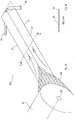
- a sheet 60 is rolled along a reel 62 configured to rotate about an axis 63.
- the sheet 60 is unrolled and the tubular element 61 is formed with the aid of a commonly known forming device (not shown in the drawing).
- Tubular element means a sheet having a flattened tube structure that extends along a direction.
- the tubular element is formed from a sheet through two mutually parallel fold lines L1.
- the two fold lines L1 allow moving the outer edges of the sheet 60 closet to each other so that the right edge of the sheet is positioned at the left edge of the sheet. The point wherein the right edge of the sheet meets with the left edge of the sheet coincides with the midpoint of the tubular element.
- the fold lines L1 indeed are arranged at the same distance with respect to the outer edges of the sheet 60.
- FIG. 5B An example of the structure having tubular element 61 is clearly shown in the section view A-A in figure 5B .
- Such drawing shows the fact that the tubular structure 61 has a lower edge that is continuous, while an upper edge has a slight discontinuity.
- the reason for the discontinuity lies in the fact that as described above, the upper edge of the tubular element 61 comprises the right edge of the sheet 60 and the left edge of the sheet 60 placed at each other. Therefore, there is a central portion of the upper edge of the tubular element 61 that represents a transition portion between the left edge and the right edge of the sheet 60.
- the forming device that folds the sheet 60 along the fold lines L1 allows positioning the outer edges of the sheet 60 at each other so as to substantially make such discontinuity zero. It is worth noting that for illustrative purposes, such distance between the left and right edges is rather accentuated in figure 5B so as to allow the reader to understand that it is a tubular element and that the portion where there is such discontinuity is the portion where the right edge and the left edge of the sheet 60 meet. In reality, it is apparent that the area of discontinuity provided by the forming device is much less apparent.
- FIG. 6A and 6B show the elements that allow the tubular element 61 to be folded and conveyed.
- figure 6A shows that the conveying of the tubular element 61 along a direction perpendicular to the conveying direction of the sheets 19 and 20 shown in figure 3 , is ensured by counter-rotating rollers 66 placed at two different levels.
- the tubular element 61 is conveyed below a plate 67 on which there are provided two openings 68 which allow the counter-rotating rollers 66 to directly contact the tubular element and to convey it along a conveying direction by means of the rotation thereof.
- the number of openings 68 is equal to two, the number of rollers is therefore equal to four.
- the sheet 60 is a sheet made of flexible material having a welding surface and a non-welding surface.
- the welding surface is the one external to the tubular element 61 that therefore forms the outer surface of the tubular element, while the non-welding surface is the inner one with respect to the tubular element 61.
- each pair of rollers 66 positioned respectively above and below the plate 67 comprises two rollers 66, wherein one roller is configured so as to rotate in opposite direction with respect to the roller positioned above/below it.
- the folding means 64 and 65 are positioned at the bottom with respect to the tubular element 61 so that the tubular element 61 may slide over them.
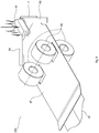
- folding means 64 and 65 are shown more clearly with reference to figure 7A .
- such means have a substantially rectangular shape.
- such folding means 64 and 65 have an inner edge having a form that deviates from the rectilinear one in the particular state shown in figure 7A (that is, after they have performed the rotation about the axis thereof, thus forming the arrow structure).
- the central "pointed" end portion allows optimizing the folding process.
- the cavity positioned at the central end portion of the folding means 64 and 65 allows securing the fold by means of welding, as will be more apparent when the welding means 44 are described.
- the fold of the end portion of the tubular element 61 is ensured by the joint operation carried out by the folding means 64 and 65 and by the inclined edges 67a of the end edge of the plate 67 that have a similar shape to the one of the folding means 64 and 65.
- the end edge of the plate 67 has two portions 67a that are inclined with respect to the axis of the tubular element 61 and are symmetrical with respect thereto. Such inclined portions 67a substantially are arranged parallel to the folding means 64 and 65.
- the end edge of the plate 67 has a substantially rectangular opening 67b positioned at the axis of the tubular element 61.
- an end portion of the tubular element having a substantially trapezoidal shape is formed by means of the fold of the end portion of the tubular element 61.
- Figure 7B shows a section view along the cutting line B-B in figure 7A .
- the section view there are two triangular portions 6 and 7 that, after the fold is made, are not perfectly resting on the tubular element 61 itself due to the fact that the end portion of the plate 67 is comprised between the tubular element 61 and the triangular portions 6 and 7.
- Figure 8 clearly shows a top view of the state of the end portion of the tubular element 61 after the fold is made by means rotating the folding means 64 and 65 about the axis thereof, with the coparticipation of the oblique end portion 67a of the plate 67 that allowed making the fold along the fold lines L2 that coincide with the inclination of the oblique end portion 67a.
- Figure 9 shows a successive state with respect to the one shown in figure 8 .
- a seal between the triangular portions 6 and 7 and the central portion of the tubular element 61 is made in this state due to the fact that the oblique portions 67a are placed at a given distance due to the rectangular opening 67b, as mentioned above.
- the triangular portions 6, 7 it is possible to secure the triangular portions 6, 7 to the tubular element 61 itself so that the fold line L2 that was provided in the preceding step is kept following a successive movement of the tubular element 61.
- the welding means 44 allow welding the triangular portions 6 and 7 to the tubular element 61 by means of two seal stretches 28 that extend mutually parallel along the sides of the triangular portions 6, 7.
- each of the two seal stretches 28 seals respectively one of the triangular portions 6, 7 to the tubular element 61.
- the number of seal stretches 28 may vary, as the shape of such stretches may vary.
- the triangular portions 6, 7 could also be "tacked" to the tubular element 61 by means of one or more circular seal spots positioned at the axis of the tubular element 61, wherein such seal spots preferably would allow simultaneously welding both triangular portions 6, 7 to the tubular element 61.
- shape of the tacking can also be other than circular, such as for example ellipsoid-shaped.
- tack spots alternatively can also be made in side portions with respect to the axis of the tubular element 61.
- the tubular element 61 is conducted into a portion comprised between the front sheet 19 and the back sheet 20 along a direction perpendicular to the conveying direction of the sheets 19 and 20.
- the tubular element 61 is conveyed into the inner area between the sheet 19 and the sheet 20, at the welding surface 24 that was made before, so that the axis of the tubular element 61 coincides with the symmetry axis (perpendicular to the edges 19, 20) of the welding surface 24. This contrivance is important because in this manner, it is possible to make packages having a central symmetry axis.
- the conveying of the tubular element 61 is ensured by the rotation means 66 that allow the insertion thereof into the portion comprised between the front sheet 19 and the back sheet 20.
- the tubular element 61 is inserted until the upper base 16 reaches a distance h2 with respect to the edge of the sheet 19, 20 that is opposite to the one 37, 38 at which the tubular element 61 was inserted.
- the distance h2 preferably is in the range of tens of a millimetre, for example greater than or equal to 40 mm, more preferably greater than or equal to 50 mm. Such distance strongly depends on the sizes of the package 100. As described above with respect to the package 100, this distance h2 allows having the great advantage that an upper portion of the package 100 is free from gussets at which a reclosable opening 15 can be positioned.
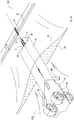
- the tubular element 61 After the tubular element 61 has reached such distance h2 from the opposite edge with respect to which it was inserted, the tubular element 61 is cut through cutting means 33 along the cutting line L3 placed at a distance D2 with respect to the lower edge of the package so as to separate a tubular element portion 69.
- This distance D2 was already described above with reference to the package in figure 1 and as mentioned above, serves to allow effectively closing the side gussets 3, 4 within a lower welding surface 27. Therefore, the cutting means 33 are positioned between the front sheet 19 and the back sheet 20 to allow such cutting.
- the tubular element portion 69 is conveyed into the area comprised between the sheets 19 and 20 until the tubular element portion 69 reaches the distance h2 from the above-described edge and therefore, accordingly reaches the distance D2 from the edge at which such tubular element portion 69 is inserted.
- a further welding surface 29 is made that allows welding the three components together.
- Such welding surface 29 can have various shapes.
- the seal is obtained by means of a welding surface 29 that circumscribes both the seal stretches 28 shown in figure 10 .
- welding could alternatively be obtained by means of one or more seal spots having for example, circular shape.
- welding surfaces may be obtained.
- larger welding surfaces can also be applied, that also interact with the welding surface 24 made beforehand.
- the tubular element 61 to which the tubular element portion 69 cut beforehand was secured is brought back, following the direction shown by the arrow in figure 12 .
- Such translation is ensured by the rotation of the rotation means 66 that rotate in the opposite direction with respect to what is described for example, in figure 10 . It is apparent that such rotation of the rotation means 66 to cause the tubular element 61 to retract towards the folding means 64, 65 becomes necessary because the tubular element 61 was cut at the area comprised between the two sheets 19, 20.
- Such rotation described here is not necessary if the cutting means 33 are positioned at a given distance from the sheets 19, 20, for example upstream of the folding means 64 and 65.
- the folding means 64 and 65 make a new fold on the end portion of the tubular element 61 and in the same manner, the front and back sheets 19, 20 to which the tubular element portion 69 was sealed are caused to slide along the conveying line shown in the drawing, which allows reaching the successive stations that are described with reference to figure 14 .
- FIG 14 indeed shows that the welding 21 that allows making the actual package 100 occurs in a successive section of the coupling station 202. Indeed, welding surfaces 21 are obtained perpendicular to the conveying direction, which form the side seals 22, 23 of the package 100, as described with reference to figure 1 .
- the welding surface 21 overlaps the welding surface 24 obtained by the welding grippers 43 and the welding surface 29 obtained to secure the tubular element portion 69 to the sheets 19, 20 so as to prevent the tubular element portion 69 from moving during a conveying towards the area of the machine wherein the welding surface 21 is obtained.
- the central axis of the welding surface 21 coincides with the central axis of the sealed surface 24.
- the seal 21 has a width equal to twice the above-described distance D1, plus a predetermined quantity that will allow forming the triangular portions 6, 7 of the tubular element at the edges of the package 100.
- seals 27 for the lower closure of the package and the oblique seals 25 and 26 that as described above, allow preventing the content of the package to possibly remain in the corners of the package itself and to provide the package 100 with a flat bottom.
- the package 100 is ready to be separated from the sheet itself so as to form a true package. Therefore, it is possible to separate the packages 100 from one another by making a cut along the cutting line L4 by means of the cutting means 34.
- the cutting line L4 is perpendicular to the conveying direction of the packages and divides the seal 21 into two perfectly equal parts.
- the reclosable opening 15 preferably is in an open state, that is in a state wherein the first portion of the reclosable opening 15 positioned on the inner side of the front panel 1 is uncoupled from the second portion of the reclosable opening 15 positioned on the inner side of the back panel 2. In this manner, it is possible to provide packages 100 that are ready to be filled without the need to uncouple the first portion from the second portion of the reclosable opening 15, which could result in an increased waste of time.
- a carousel may be placed at this point that is configured so as to receive the packages 100 provided by the coupling station 202, to open them so as to insert the contents of the package through the opening 5 of the package 100.
- the package 100 is opened in a successive step, forming an open package 101, the open package 101 is then filled by means of a funnel, thus forming a filled package 102.
- the filled package 102 is then closed, forming a closed package 103 that is then sealed, thus forming the package 105 shown in the drawing that can then be provided to the outside.
- the preparing station 201 can perform the operations described above while the tubular element forming station 203 makes the tubular element 61.
- continuous means a process that allows making packages one after another, thus with a temporal distance between making one package and the next.
- continuous here therefore means that while one station performs a given process on a package, another station performs another process on another package, that is that each station preferably can work continuously.
- the temporal distance between making two successive packages is due to the fact that the different steps are to be performed along the production line of the packages: from the various seals to the various folds.
- the present invention is also valid for packages that do not have a reclosable opening.
- the machine comprises four stations, it is possible to make a machine that contains only some of such stations.
- the filling station 204 may be omitted in many cases wherein the production of packages and not the filling thereof, is required.
- the preparing station 201 is a vertical station, it also is alternatively possible for such station to be a horizontal preparing station. Moreover, both with regards to the preparing station 201 and to the tubular element forming station 203, when reel is discussed, it means more generally any system capable of continuously providing a strip of sheet or a reclosable opening.
Landscapes
- Engineering & Computer Science (AREA)
- Mechanical Engineering (AREA)
- Bag Frames (AREA)
- Containers And Plastic Fillers For Packaging (AREA)
- Making Paper Articles (AREA)
- Auxiliary Devices For And Details Of Packaging Control (AREA)
Description
- The present invention relates to the field of sealable packages. More specifically, the present invention relates to the field of sealable packages made of flexible material having side gussets, which preferably further have reclosable openings. Moreover, the present invention relates to the field of machines for making sealable packages and a method for making such packages.
- Packages made of flexible material are commonly used in various fields: from the food to the industrial field. Packages made of flexible material for example, are commonly used to contain flour, grated cheese or the like, or alternatively for storing animal food, such as kibble for dogs or for cats.
- Such packages have various sizes according to the use made of such packages. In the case of pet food for example, such packages have also very large sizes to allow storing an increased quantity of food.
- For this purpose, to allow an increase of material stored in the packages, front area of the package being equal, such packages are provided with side gussets which allow the package to extend in depth so as to allow a significant increase of the inner volume.
- Such side gussets normally are an accordion structure, which most times is a simple sheet made of flexible material folded in half and placed at opposite ends of the front panel and of the back panel of the package so as to connect the front panel to the back panel.
- An example of a method that allows making such packages is shown in Japanese Patent
JP 3 733 085 B2 Figure 13 of PTL1 shows that thetubular element 1, from which right and left side gussets of two successive packages are made, is conveyed between two layers ofstrip 2 which form the front panel and the back panel of the final package. - Once conveyed between the two
strips 2, suchtubular element 1 first is secured to thestrips 2 by means of threeseal spots 24 and then the two end portions of the tubular element are folded, at which slits 17 are positioned that allow the passage of the air. Indeed, PTL1 clearly shows the formation of an open, and therefore not sealable, package that allows the passage of air from the outside to the inside of the package by means of the slits 17. - As shown in
figure 15 of PTL1, the folding is ensured by the folding means 22 and 25 which, by means of the cooperation thereof, allow having an end portion of thetubular element 1 having a pointed shape. Such pointed portion is formed by two right-angled triangles placed adjacent to each other. After such folding, the folding is secured by means of a forthseal spot 24. - As is apparent from the above description of PTL1, this system has several disadvantages, two of which are described here.
- A first disadvantage is that the author of PTL1 has positioned the
tubular element 1 between twostrips 2 that are completely free to move with respect to each other. If on the one hand this solution might seem advantageous because it allows having more space to position the various sealers and the folding means between the two strips, on the other it implies a significant slowing down of the package forming process because an increased number of operations at the same point in space are to be performed for such purpose on thestrips 2 and on thetubular element 1 before conveying thestrip 2 towards a successive sub-station. - A second disadvantage is that there is an increased difficulty in achieving an increased accuracy in positioning the
tubular element 1 with respect to thestrips 2 in the system described in PTL1. This is because the increased number of components present therein and the simultaneous increased degree of freedom of the various components results in an increased level of difficulty in positioning the tubular element at a more accurate point of thestrips 2 with a given accuracy. -
US 2001/053253 A1 relates to a method and a machine for making flexible packages wherein a first strip of flexible material is secured to a second strip of flexible material by means of a welding surface, the first and second strip being positioned on top of each other and being moved in a conveying direction. Said welding surface extends in a direction perpendicular to said conveying direction and is positioned at a first side edge of said first and of said second strip. The flexible packages do not comprise side gussets. -
US 2004/258332 A1 discloses a method and a machine for making flexible packages wherein tubular elements which will form side gussets are conveyed between a first and a second strip which strips are completely spaced apart from each other. - For this reason, the author of the present invention has looked for a solution that would allow resolving such problems and would therefore provide a method and a machine capable of allowing an effective positioning of the tubular element with respect to the strips and would simultaneously allow achieving higher speeds for making packages with respect to that shown in PTL1.
- This problem is solved with a method comprising the features of
claim 1 and a machine comprising the features ofclaim 9. - The present invention is based on the idea of making a welding surface that allows pre-securing the two strips so that the first strip and the second strip can be partially moved with respect to each other in the successive stations without however them being completely moved with respect to one another because they are already pre-secured.
- According to the present invention, a method for making packages is provided, the method comprising the following steps:
- a) providing a first strip and a second strip made of flexible material, positioned on top of each other along a conveying direction and preferably having the same width;
- b) securing the first strip to the second strip by means of a welding surface which extends in a direction perpendicular to the conveying direction of the first and the second strip for a first length which is less than the width of each of the first and the second strip; the welding surface is positioned at the first side edge of the first strip and the second strip.
- This solution is particularly advantageous because it allows pre-securing the two strips before the tubular element is introduced between the two strips. Indeed, having defined that the extension of the welding surface is less than the width of each of the first and the second strip clearly implies that such welding surface does not correspond to the one made for the actual closure of the package, rather corresponds to a pre-securing configured so as to pre-secure the two strips. Therefore, this pre-securing is particularly advantageous because it allows securing the two strips upstream and leaving free a portion of the strips for introducing the tubular element that forms the side gussets of the package. With respect to the background art, and more particularly with respect to PTL1, this solution is particularly advantageous because it allows both allowing an increased accuracy in the successive positioning of the tubular element and reducing the number of operations to be performed in the coupling station, while at the same time ensuring a sufficient space for introducing the tubular element. Moreover, due to such welding surface, it is possible to position the side gussets at a predetermined distance from the first side edge of the strips so as to have an upper portion of the final package free from gussets, thus allowing to apply a reclosable opening at such portion. In the same manner, if the two strips have the same width, it is possible to position the side edges of the two strips at each other so as to use such side edges of the strips as upper and lower edge of the final package.
- According to a particular embodiment of the present invention, a method for making packages is provided, wherein a distance between two midpoints of two of the welding surfaces that are positioned consecutively along the conveying direction is equal to the width of the package, wherein the distance is measured along the conveying direction. This solution is particularly advantageous because it allows having welding surfaces that allow pre-securing the two strips that have a distance equal to the final package, thus allowing the welding surfaces to be "encompassed" in the side seals of the package. Therefore once the package is made, such welding surfaces are not visible from the outside, thus allowing to have a final product that is visually similar to the one that would be obtained without the presence of such welding surfaces. According to a particular embodiment of the present invention, a method for making packages is provided, wherein an edge of the welding surface is positioned along the first side edge of the first and the second strip. This solution is particularly advantageous because it allows positioning such welding surface along an edge of the strips and leaving free the opposite edge so as to convey for example, the tubular element that serves to make the gussets at the other side edge of the strips.
- According to a particular embodiment of the present invention, a method for making packages is provided, wherein the first length, along which the welding surface extends, is less than half the width of the first strip and the second strip, the first length preferably being comprised between 35 mm and 50 mm, more preferably the length is equal to 50 mm. Such solution is particularly advantageous because it allows having an upper portion of the final package free from gussets wherein such portion is less than half the axial extension of the package. Moreover, the above-indicated preferable range wherein the first length is comprised allows having an upper portion free from gussets equal to at least 35 mm. This contrivance allows for example, installing a reclosable opening at this area.
- According to a particular embodiment of the present invention, a method for making packages is provided, wherein during step a), the first and the second strip are made from a third strip coming from reel, wherein the first and the second strip preferably are obtained by folding the third strip coming from reel along a fold line coinciding with the axis of the third strip so as to arrange the side edges of the third strip at one another and by cutting the third strip along such fold line. This solution is particularly advantageous because it allows having a single reel from which the two strips are obtained. This implies for example, being able to effectively reduce the sizes of the machine and replacing one reel alone, if it is used up. It is apparent that the term axis of the third strip here means the axis along which the third strip is unrolled and passing through the midpoint of the third strip.
- According to a particular embodiment of the present invention, a method for making packages is provided, wherein the method further comprises the following step:
d) providing a reclosable opening between the first strip and the second strip so as to position the reclosable opening, along a direction parallel to the conveying direction, at a distance from the first edge that is less than the first length so as to secure the reclosable opening between the first strip and the second strip by means of the welding surface. - This solution is particularly advantageous because it allows effectively taking advantage of the welding surface that as mentioned, allowed pre-securing the two strips also to secure the reclosable opening between the first strip and the second strip, thus serving a dual purpose. This means that the reclosable opening is conveyed along a direction parallel to the one of the strips so as to effectively position such opening parallel to the upper edge of the package. Moreover, such reclosable opening preferably is provided from reel so as to be provided in continuous manner. Such reclosable opening preferably is a reclosable zipper length that is secured both to the front strip and to the back strip so as to secure a portion to each of the strips and thereby to ensure a closure of the final package. Indeed, by engaging the first portion of the reclosable opening with the second portion of the reclosable opening, it is possible to close the upper opening of the package after the package itself was opened the first time.
- According to the present invention, a method for making packages is provided, wherein after the first strip is secured to the second strip by means of the welding surface, a second side edge of the first strip and a second side edge of the second strip, which are opposite to the first side edge, are moved away from each other so as to form an empty space between the first strip and the second strip, wherein the empty space extends from the second edge to the welding surface. This solution is particularly advantageous because it allows opening the first strip from the second strip without there being the risk for the two strips to move laterally with respect to each other because they were pre-secured as mentioned above, by the welding surface. Therefore, this opening allows moving the first strip away from the second strip along a side edge and therefore, conveying the tubular element that forms the side gussets of the package by means of such opening.
- According to a the present invention, the method further comprises the following step:
c) conveying a tubular element that forms side gussets of the package into the empty space until an end portion of the tubular element reaches a first distance from the first side edge, wherein the first distance is greater than or equal to the first length; wherein the tubular element preferably is conveyed along a direction perpendicular to the conveying direction of the first and the second strip. - This solution is particularly advantageous because it allows using the space formed between the two strips to introduce the tubular element itself, which as mentioned, forms the side gussets of the package. As is apparent from what is described, this solution allows uncoupling the point wherein the welding of the welding surface occurs and the point wherein the tubular element is inserted, due to the provision of the above-described welding surface. This has allowed the inventor to allow an actual reduction of the production times of a single package. Moreover, the fact that the first distance is greater than or equal to the first length allows positioning the tubular element at the bottom with respect to the welding surface, thus allowing to have a package having an upper portion free from gussets.
- According to a particular embodiment of the present invention, a method for making packages is provided, wherein the tubular element is made by folding a sheet made of flexible material along two mutually parallel first fold lines so as to form the tubular element, and by folding an end portion of the tubular element along two second fold lines that are oblique with respect to the direction of the two first fold lines so as to form an end portion of the tubular element that has two triangular portions having two mutually parallel sides. This solution is particularly advantageous because it allows obtaining side gussets having an inclined surface. Moreover, this solution allows providing such empty space with an already "ready" tubular element without the need to perform the various folding operations in such empty space. This therefore allows significantly reducing the time for producing the packages.
- According to a particular embodiment of the invention, a method for making packages is provided wherein, after the tubular element is conveyed into the empty space between the first strip and the second strip, the tubular element is secured to the first strip and to the second strip by means of a second welding surface. This solution is advantageous because it allows securing together all the elements, thus effectively avoiding a movement that could occur between the various components. In this manner, it is thus possible in a successive step to convey the two strips without the tubular element portion moving with respect thereto.
- According to a particular embodiment of the present invention, a method for making packages is provided, wherein the packages are sealable packages. This implies that the package allows sealing the atmosphere inside the package with respect to the atmosphere outside the package, for example by allowing the organoleptic properties of the material contained in the package to be kept.
- According to the present invention, a machine for making packages made of flexible material is provided; the machine comprises a preparing station configured so as to provide a first strip and a second strip positioned on top of each other along a conveying direction; wherein the preparing station comprises first welding means configured so as to make a welding surface which extends in a direction perpendicular to the conveying direction of the first and the second strip for a first length which is less than the width of each of the first and the second strip; the welding surface is positioned at a first side edge of the first and the second strip. This solution is particularly advantageous because it allows pre-securing the two strips before the tubular element is introduced between the two strips due to the first welding means. Indeed, having defined that the extension of the welding surface is less than the width of each of the first and the second strip clearly implies that such welding surface does not correspond to the one made for the actual closure of the package, rather corresponds to a pre-securing configured so as to pre-secure the two strips. Therefore, this pre-securing is particularly advantageous because it allows securing the two strips upstream and leaving free a portion for introducing the tubular element that forms the side gussets of the package. With respect to the background art, and more particularly with respect to PTL1, this solution is particularly advantageous because it allows both allowing an increased accuracy in the successive positioning of the tubular element and reducing the number of operations to be performed in the coupling station, while at the same time ensuring a sufficient space for introducing the tubular element. Moreover, due to such welding surface, it is possible to position the side gussets at a predetermined distance from the first side edge of the strips so as to have an upper portion of the final package free from gussets, thus allowing to apply a reclosable opening at such portion. In the same manner, if the two strips have the same width, it is possible to position the side edges of the two strips at each other so as to use such side edges of the strips as upper and lower edge of the final package.
- According to a further embodiment of the present invention, a machine for making packages made of flexible material is provided, wherein the first length is less than half the width of the first strip and the second strip, the first length preferably being comprised between 35 mm and 50 mm, more preferably the length is equal to 50 mm. Such solution is particularly advantageous because it allows having an upper portion of the final package free from gussets wherein such portion is less than half the axial extension of the package. Moreover, the above-indicated preferable range wherein the first length is comprised allows having an upper portion free from gussets equal to at least 35 mm. This contrivance allows for example, installing a reclosable opening at this area.
- According to a further embodiment of the present invention, a machine for making packages made of flexible material is provided, wherein the preparing station further comprises folding means configured so as to fold a third strip coming from reel along a fold line that coincides with the axis of the third strip so as to arrange the side edges of the third strip one at the other, and cutting means configured so as to cut a third strip along the fold line so as to allow obtaining the first and the second strip. This solution is particularly advantageous because it allows having a single reel from which the two strips are obtained. This implies for example, being able to effectively reduce the sizes of the machine and replacing one reel alone, if it is used up. It is apparent that the term axis of the third strip here means the axis along which the third strip is unrolled and passing through the midpoint of the third strip.
- According to a further embodiment of the present invention, a machine for making packages made of flexible material is provided, wherein the preparing station further comprises second welding means configured so as to seal a reclosable opening at the first and the second strip, the second welding means being positioned at the first edge along a direction parallel to the conveying direction. This solution is particularly advantageous because it allows welding the reclosable opening to each of the two strips along the direction wherein the reclosable opening extends. Moreover, such reclosable opening preferably is provided from reel so as to be provided in continuous manner. Such reclosable opening preferably is a reclosable zipper length that is secured both to the front strip and to the back strip so as to secure a portion to each of the strips and thereby to ensure a closure of the final package. Indeed, by engaging the first portion of the reclosable opening with the second portion of the reclosable opening, it is possible to close the upper opening of the package after the package itself was opened the first time.
- According to a further embodiment of the present invention, a machine for making packages made of flexible material is provided, wherein the welding surface allows securing the reclosable opening in a side area of the package. This solution is particularly advantageous because it allows effectively taking advantage of the welding surface that as mentioned, allowed pre-securing the two strips also to secure the reclosable opening between the first strip and the second strip, thus serving a dual purpose. This means that the reclosable opening is conveyed along a direction parallel to the one of the strips so as to effectively position such opening parallel to the upper edge of the package. Moreover, this solution also allows flattening a side portion of the reclosable opening, therefore decreasing the thickness resulting therefrom.
- According to a further embodiment of the present invention, a machine for making packages made of flexible material is provided, wherein the second welding means are positioned upstream of the first welding means. This solution is particularly advantageous because it allows inserting an element, such as a contrast element, between the two welding means so as to allow the continuous opening of the reclosable opening after it is coupled to the front and back strip.
- The present invention is described with reference to the accompanying drawings wherein the same reference numbers and/or marks indicate the same parts and/or similar parts and/or corresponding parts of the system.
-
Figure 1 shows a front view of a package made of flexible material according to an embodiment of the present invention. -
Figure 2 shows a three-dimensional schematic view of a machine for making a package shown infigure 1 , according to a particular embodiment of the present invention; wherein the dotted lines show ideal separation lines between the different stations of the machine. -
Figure 3 more specifically shows the various components of the machine for producing packages depicted infigure 2 , according to a particular embodiment of the present invention. -
Figure 4 shows a detail of a first station of the machine described infigure 3 . -
Figure 5A shows a detail of a second station of the machine described infigure 3 , wherein there is formed a tubular element according to a particular embodiment of the present invention, whilefigure 5B shows a section view of thetubular element 61 taken along the cutting line A-A infigure 5A . -
Figure 6A shows a detail of the tubular element forming station, more specifically it shows the system for moving the tubular element and for forming the fold lines that are oblique with respect to the axis of the tubular element, whilefigure 6B shows a section view taken along the cutting line A-A shown infigure 6A . -
Figure 7A shows the detail of the tubular element forming station shown infigure 6A , in a successive state, after an end portion of the tubular element was folded along fold lines that are inclined with respect to the axis of the tubular element;figure 7B instead shows a section view along the cutting line B-B shown infigure 7a , and in particular it shows a section view of thetriangular portions -
Figure 8 shows a top view of the detail shown infigure 7A . -
Figure 9 shows a three-dimensional view of the detail shown infigure 7A , in a successive state after thetriangular portions tubular element 61. -
Figure 10 shows a three-dimensional view of the tubular element forming station shown infigure 9 , and of a coupling station wherein the tubular element is inserted between the sheets coming from the first station shown infigure 4 . -
Figure 11 shows a three-dimensional view of the stations depicted infigure 10 , in a successive state, after the tubular element is cut along a cutting line. -
Figure 12 shows a three-dimensional view of a successive state with respect to the one shown infigure 11 . -
Figure 13 shows a three-dimensional view of the detail shown infigure 12 , in a successive state with respect to the one shown infigure 12 . -
Figure 14 shows a top view of the portion of machine shown infigure 13 , showing the various seals made. -
Figure 15 shows a top view similar to the one shown infigure 14 , which shows a successive state to the one shown infigure 14 , that is when one package is separated from the following one. -
Figure 16 shows a final state wherein the packages shown infigure 15 are brought into a closing station configured so as to fill the packages with product, close them and supply them to the outside. - The present invention is described hereinbelow by making reference to particular embodiments, as illustrated in the accompanying drawings. However, the present invention is not limited to the particular embodiments described in the following detailed description and depicted in the drawings, rather the embodiments described simply exemplify the various aspects of the present invention, the scope of which is defined by the appended claims. Further modifications and variations of the present invention will be apparent to those skilled in art.
- Reference is made to the plane on which the
sealable package 100 rests when reference in the present description is made to the terms "right", "left", "top", "bottom", "front" and "back". Therefore, the plane on which thesealable package 100 rests is a plane which is at the opposite side with respect to the one wherein the opening of the package is positioned. Therefore, the term "top" means a portion of the package placed at the opening of the package, through which the contents of the package may be inserted. Moreover, with respect to the plane on which thepackage 100 rests, right refers to the right side of the reader and similarly, left refers to the left side of the reader; finally, front is the portion of package facing the side of the reader and similarly, back refers to the opposite side with respect to the reader. - The term conveying direction in the present invention means a direction along which the
package 100, or parts thereof, is made. In this logic, if one process is performed "downstream" with respect to another, it means that during the process leading to making thepackage 100, such process is performed after another process was performed. In the same manner, if one process is performed "upstream" with respect to another, it means that during the process leading to making thepackage 100, a process is performed before another process was performed. -
Figure 1 diagrammatically illustrates asealable package 100 according to an embodiment of the present invention. -
Figure 1 shows a front view of thepackage 100; in particular, theupper opening 5 of the package is positioned at an upper end of the drawing, while thelower edge 12 of thepackage 100 is positioned in the lower part of the drawing. - The
package 100 is sealable because, as will be apparent from the following description, after filling thepackage 100 through theupper opening 5 and having made, atsuch opening 5, a welding surface adapted to close the opening of the package, it will be impossible for the atmosphere outside the package to enter the package. Therefore, the environment inside thepackage 100 will be completely isolated with respect to the external environment of thepackage 100. - The details of the
package 100 described infigure 1 are now described, which will be apparent in the continuation of the description when the method for making the package is explained with reference to the following drawings. - The
sealable package 100 made of flexible material comprises afront panel 1 and aback panel 2. Thefront panel 1 and theback panel 2 are connected by two side gussets: aright side gusset 3 and aleft side gusset 4.Such side gussets front panel 1 and of theback panel 2. The twoside gussets front panel 1 and theback panel 2. - Clearly, it is also possible for the
side gussets - The
front panel 1, theback panel 2 and the twoside gussets - Forthis reason, the
front panel 1 and theback panel 2 have the sealable surfaces facing the inside of thepackage 100. In the same manner, theside gussets package 100. In particular, theside gussets front panel 1 and theback panel 2 so as to allow a seal between theside gussets back panels package 100 to be ensured. - As shown in the drawing, the package has a
reclosable opening 15 positioned at an area close to theopening 5 of thepackage 100. Suchreclosable opening 15 preferably extends along a direction perpendicular to the axis Ax1 of thepackage 100. Moreover as described later, the reclosable opening is comprised between the side welding surfaces 22, 23. An example of reclosable opening is given by a zipper which allows reversibly opening and closingsuch package 100. Thereclosable opening 15 therefore extends between thefront panel 1 and the back panel 2: a first portion of thereclosable opening 15 is installed on the inner surface of thefront panel 1 of thepackage 100, while a second portion of thereclosable opening 15 is installed on the inner surface of theback panel 2 of thepackage 100. In this manner, the first portion can be engaged with the second portion so as to ensure the closure of thepackage 100 also after thepackage 100 has been opened for the first time. - An upper end portion of the
side gussets package 100. The portion folded along the fold line L2 therefore is an end portion of eachside gusset opening 5 of thepackage 100. - The formation of
triangular portions side gussets side gussets package 100 free from gussets. This allows positioning thereclosable opening 15 in the area where there are only two layers of material (area having two thicknesses): the layer of thefront panel 1 and the layer of theback panel 2. - The
triangular portions triangular portion package 100, is positioned in a side area of the package at which the seal is made (which is further explained later), which allows joining thefront panel 1 to theback one 2 with theside gussets - Each of the two
triangular portions cathetus outer edge cathetus outer edge package 100. - As shown in the drawing, each
cathetus outer edge package 100 is explained, this allows welding thefront panel 1 to thegussets back panel 2, therefore "trapping" eachtriangular portion - Contrarily, if the
cathetus edge package 100, the risk would exist of not having a perfect seal of thepackage 100 with respect to the outside. Moreover, there would also be the problem of the formation of a kind of "side tab" placed at the upper portion of the gusset, which would in some manner risk breaking, therefore resulting in a particularly weak and fragile package. - As is shown in the drawing and as mentioned above, side seals 22, 23 are made at the right 10 and left 11 side edges of the package, said seals allowing to close the
package 100 along the right side and the left side.Such seals - In this manner, a portion of the
cathetus side welding area triangular portion - As mentioned, the width of the
welding surface front panel 1 and theback panel 2. In particular, such predetermined distance D1 may preferably be greater than or equal to 1 mm, and in certain cases, also have larger sizes. For larger packages for example, the distance D1 preferably is greater than or equal to 4 mm. It is apparent that such distance strongly depends on the sizes of the package. For example, smaller packages have a smaller distance D1. Vice versa, larger packages have a larger distance D1. In the same manner, the distance D1 depends on the width of the side welding surfaces 22 and 23. To this end, the wider such surfaces, the greater the distance D1. - In addition as shown in the drawing, a
lower welding surface 27 adapted to close the bottom of thepackage 100 so as to prevent the material contained in the package to come out from the bottom, is positioned along thelower edge 12 of thepackage 100. Furthermore, there are two weldingsurfaces welding surface welding surface 27 to allow effectively emptying the package and at the same time strengthening the lower edges. The effective emptying is due to the fact that the welding surfaces 25 and 26 allow having a bottom of the package that is flat, and therefore easier to empty. - This contrivance allows the material contained in the
package 100 to effectively exit, which otherwise could be trapped at the lower corners of thepackage 100. Indeed, it is the object of the welding surfaces 25 and 26 to also reduce the possibility of part of the contents of the package to remain trapped at the lower edges. - For example, in the case wherein the value of the material contained in the package is particularly high, for example in the case of food products, there would be a serious waste which in any case is to be reduced.
- Moreover, the
side gussets lower edge 12 of thepackage 100. This is due to the fact that in this manner, the lower portion of the gussets may be "trapped" between thefront panel 1 and theback panel 2. Such distance D2 may vary according to the size of thepackage 100. As an indicative value, such distance preferably is greater than or equal to 1 mm. Moreover, most of the time such distance preferably is less than 5 mm. - Packages like the ones shown in
figure 1 may have a wide range of sizes. For example, they may have a size that varies from relatively small packages, configured so as to contain 0.1 kg of material, to much larger packages, that allow containing up to 20 kg of material. - Summarizing therefore, the
right side gusset 3 and theleft side gusset 4 extend along theside edge lower edge 12 of thepackage 100. Therefore as shown in the drawing, the height h3 of thepackage 100 is equal to the sum of the distance h2 of the upper end portion of thegussets upper edge 5, with the distance h1.Such gussets lower edge 12 of thepackage 100 which therefore is represented by the lower edge of thefront panel 1 and of theback panel 2. Moreover, the upper end portion of the right 3 and left 4 side gusset is positioned at a distance h2 of theopening 5 of thepackage 100. This allows having an inner portion of thepackage 100 free from gussets and therefore also an effective exit of the material contained in thepackage 100. - With reference to
figures 2 to 16 , amachine 200 for makingpackages 100 like the ones infigure 1 and a method for makingsuch packages 100, are described. -
Figure 2 shows amachine 200 according to an embodiment of the present invention. Themachine 200 shown in the drawing comprises four stations. Afirst station 201 is configured so as to prepare a strip of material which is then coupled instation 202 with the tubular element coming from thestation 203. Thestation 203 is then configured so as to form theside gussets package 100, which are shown infigure 1 . Downstream of thecoupling station 202, there is positioned apackaging station 204 wherein the package produced in thecoupling station 202 is opened, filled with the contents of the package and finally closed at theopening 5 of thepackage 100 so as to seal the environment inside the package with respect to the external environment. - With reference now to
figure 3 , the preparingstation 201, which is a vertical station in the particular example depicted in the drawing, thecoupling station 202 and the tubularelement forming station 203, are described in detail. - The method for making the
package 100 will be apparent from the description of the various stations of themachine 200 and of how such stations contribute to making thepackage 100. - The preparing
station 201 comprises areel 72 on which asheet 70 made of flexible material is wound, which as mentioned above, is sealable on one of the two sides. - The
sheet 70 is unrolled from thereel 72 and conducted towards a formingdevice 73 which allows bending the sheet in half so as to form a folded sheet having a width equal to half the width that thesheet 70 had when it was positioned on thereel 72. - As mentioned, the
sheet 70 is unrolled from thereel 72 and conveyed along the conveying direction indicated by the arrow infigure 3 towards the formingdevice 73, where it is folded. Ablade 71 is positioned immediately downstream of the formingdevice 73, which blade allows cutting thesheet 70, therefore dividing it into two equal parts along the fold line that was provided by the formingdevice 73. - Therefore, downstream of the blade, there will be 71 two
sheets sheets - Alternatively, it is obviously also possible to replace the above-described system with two reels configured so as to provide the two
sheets - A
reel 74 is placed downstream of theblade 71, on which reel azipper length 15 is wound, which may be used as reclosable opening of thepackage 100. - Thus, the
zipper length 15 is unrolled from thereel 74 and coupled to bothsheets blade 71. For example, in the particular example depicted in the drawing, thezipper length 15 is coupled to thefront sheet 19 and theback sheet 20 by means of welding bars 42 which allow welding thereclosable opening 15 to what will be thepanels package 100. - As shown in the drawing, the
reclosable zipper 15 is provided fromreel 74 and is coupled both with the front sheet and with the back sheet by means of the seal provided by the welding bars 42. In particular, after thereclosable opening 15 is opened, that is after a first portion of thereclosable opening 15 is uncoupled from a second portion of thereclosable opening 15, the first portion of thereclosable opening 15 is constrained to thefront sheet 19 and the second portion to theback sheet 20. Thus, it is effectively possible to reversibly open/seal thepackage 100 by means of a successive uncoupling/coupling of the first portion from/to the second portion. - Thus as mentioned, the
reclosable zipper 15, which comprises such first and second portion, is conveyed into the portion comprised between thesheet 19 and thesheet 20 and is sealed thereto. Such portions preferably are then uncoupled from each other, after the welding has been performed by means of the welding bars 42. - Thus, a contrast element (not shown in the drawing) with the purpose of separating the first portion of the
reclosable opening 15 from the second one preferably is positioned downstream of the welding bars 42. - In this manner, as seen in the continuation of the description, it is preferable to have the two portions of the
zipper 15 uncoupled from each other in the final station where thevarious packages 100 are separated from one another so as to allow thepackage 100 to be filled without the need to first uncouple the two portion so as to provide the package with an opening for filling the same. - Welding
grippers 43 are placed downstream of the welding bars 42, which as mentioned, are configured so as to longitudinally seal thezipper 15, the welding grippers allowing to makewelding surfaces 24 along a direction perpendicular to the conveying direction of thesheets welding grippers 43. - These welding surfaces 24, which are introduced in greater detail with reference to the following drawings, allow securing the
front sheet 19 to theback sheet 20 with thereclosable opening 15 comprised betweensuch sheets zipper 15 at such welding surfaces 24 in order to reduce the thickness thereof. This then allows facilitating the side seals of the package, which are described later. - Each
welding surface 24 produced by thewelding grippers 43 is positioned close to the edge of thesheets sheets such welding surface 24, which is due for example, to margins of error required when positioning thewelding grippers 43. In any case, it is preferable for such welding surface to be positioned next to the edge of thesheets - The closing surface, which then is the upper edge of the
package 100 at which theopening 5 of thepackage 100 is positioned, extends along a direction parallel to the edge of thesheets sheets figure 13 ) between two consecutive midpoints of welding surfaces 24 is measured along the conveying direction of thesheets package 100 that is then formed. - The length h4 (shown in
figure 10 ) of such welding surfaces 24 preferably is comprised between 35 mm and 50 mm. According to a particular embodiment, such extension preferably is equal to 40 mm. In any case, the above-mentioned extensions strongly depend on the height of thefinal package 100 and therefore on the width of thesheets - It is important for such welding surfaces 24 to have a length which as described later, allows introducing a tubular element that will form the
side gussets sheets opening 5 of thepackage 100 is positioned, as described later. - The
sheets welding grippers 43 in downstream direction by means of the aid of movement elements (not shown in the drawing), which for example, are simple rollers. The procedure used by the preparingstation 201 is shown in greater detail with reference tofigure 4 . -
Figure 4 clearly shows how the front sheet and theback sheet edge welding surfaces 24 are made. Such procedure may be performed by means of a simple protruding element (not shown in the drawing), known from the prior art (and simply called separating means hereinafter), which is configured so as to be inserted between thesheets back sheet tubular element 61. Such separating means may then be represented by any system known from the prior art and capable of separating two sheets placed on top of each other and of forming an empty space therebetween, such as for example shown inWO 2015/040631 A1 . - The
edge 37 of theback sheet 20 and theedge 38 of thefront sheet 19 therefore are positioned at the one which forms thelower edge 12 of thepackage 100. - Returning again to
figure 3 , thecoupling station 202 is positioned downstream of such first preparingstation 201, the coupling station being configured so as to couple thesheet 19 and thesheet 20 coming from thefirst station 201 with thetubular element 61 coming from the tubularelement forming station 203, which is described later. - Therefore, the operating method of the tubular
element forming station 203 that provides the tubular element to thecoupling station 202 is described in detail before getting into the description of thecoupling station 202. - As shown in
figure 3 , the conveying direction of thetubular element 61 is perpendicular to the conveying direction of thefront sheet 19 and of theback sheet 20 described above. - With reference to
figures 5A and 5B , the method with which such tubular element is made is described in detail. As shown in the drawing, asheet 60 is rolled along areel 62 configured to rotate about anaxis 63. By rotating thereel 62, thesheet 60 is unrolled and thetubular element 61 is formed with the aid of a commonly known forming device (not shown in the drawing). - Tubular element means a sheet having a flattened tube structure that extends along a direction. The tubular element is formed from a sheet through two mutually parallel fold lines L1. As shown in the drawings, the two fold lines L1 allow moving the outer edges of the
sheet 60 closet to each other so that the right edge of the sheet is positioned at the left edge of the sheet. The point wherein the right edge of the sheet meets with the left edge of the sheet coincides with the midpoint of the tubular element. The fold lines L1 indeed are arranged at the same distance with respect to the outer edges of thesheet 60. - An example of the structure having
tubular element 61 is clearly shown in the section view A-A infigure 5B . Such drawing shows the fact that thetubular structure 61 has a lower edge that is continuous, while an upper edge has a slight discontinuity. The reason for the discontinuity lies in the fact that as described above, the upper edge of thetubular element 61 comprises the right edge of thesheet 60 and the left edge of thesheet 60 placed at each other. Therefore, there is a central portion of the upper edge of thetubular element 61 that represents a transition portion between the left edge and the right edge of thesheet 60. - In any case, the forming device that folds the
sheet 60 along the fold lines L1 allows positioning the outer edges of thesheet 60 at each other so as to substantially make such discontinuity zero. It is worth noting that for illustrative purposes, such distance between the left and right edges is rather accentuated infigure 5B so as to allow the reader to understand that it is a tubular element and that the portion where there is such discontinuity is the portion where the right edge and the left edge of thesheet 60 meet. In reality, it is apparent that the area of discontinuity provided by the forming device is much less apparent. - With reference to
figure 6A and 6B , they show the elements that allow thetubular element 61 to be folded and conveyed. - In particular,
figure 6A shows that the conveying of thetubular element 61 along a direction perpendicular to the conveying direction of thesheets figure 3 , is ensured bycounter-rotating rollers 66 placed at two different levels. - The
tubular element 61 is conveyed below aplate 67 on which there are provided twoopenings 68 which allow thecounter-rotating rollers 66 to directly contact the tubular element and to convey it along a conveying direction by means of the rotation thereof. In the particular example shown in the drawing, given that the number ofopenings 68 is equal to two, the number of rollers is therefore equal to four. - However, it also is possible to increase or decrease the number of
openings 68, and therefore ofrollers 66, as desired according for example, to the sizes of thetubular element 61 or also for example, to the thickness or the rigidity of the material with which thetubular element 61 is made. - As mentioned above, like the
sheet 70, thesheet 60 is a sheet made of flexible material having a welding surface and a non-welding surface. In the particular example shown in the drawing, the welding surface is the one external to thetubular element 61 that therefore forms the outer surface of the tubular element, while the non-welding surface is the inner one with respect to thetubular element 61. - As mentioned, each pair of
rollers 66 positioned respectively above and below theplate 67 comprises tworollers 66, wherein one roller is configured so as to rotate in opposite direction with respect to the roller positioned above/below it. - Folding means 64 and 65 placed oblique to the conveying direction of the
tubular element 61 shown in the drawing, are positioned at the end portion of theplate 67. The folding means 64 and 65 are positioned at the bottom with respect to thetubular element 61 so that thetubular element 61 may slide over them. As described below, it is possible to provide the end portion of the tubular element with an arrow structure by means of rotating the folding means 64 and 65 about the axis thereof. - Such folding means 64 and 65 are shown more clearly with reference to
figure 7A . As shown, such means have a substantially rectangular shape. In particular, such folding means 64 and 65 have an inner edge having a form that deviates from the rectilinear one in the particular state shown infigure 7A (that is, after they have performed the rotation about the axis thereof, thus forming the arrow structure). Firstly, the central "pointed" end portion allows optimizing the folding process. Otherwise, the cavity positioned at the central end portion of the folding means 64 and 65 allows securing the fold by means of welding, as will be more apparent when the welding means 44 are described. - In particular, the fold of the end portion of the
tubular element 61 is ensured by the joint operation carried out by the folding means 64 and 65 and by theinclined edges 67a of the end edge of theplate 67 that have a similar shape to the one of the folding means 64 and 65. - In particular, the end edge of the
plate 67 has twoportions 67a that are inclined with respect to the axis of thetubular element 61 and are symmetrical with respect thereto. Suchinclined portions 67a substantially are arranged parallel to the folding means 64 and 65. In addition, the end edge of theplate 67 has a substantiallyrectangular opening 67b positioned at the axis of thetubular element 61. - Therefore, when the
tubular element 61 that slides below theplate 67 arrives close to the end portion of theplate 67, it will be visible at the centralrectangular portion 67b of theplate 67. This configuration is advantageous because it is possible to seal thetriangular portions tubular element 61 to thetubular element 61 itself, at therectangular opening 67b, after the fold was made by the folding means 64 and 65 with the aid of theinclined edges 67a of theplate 67. As described above, the access to therectangular portion 67b is also ensured by the particular shape of the end portion of the folding means 64 and 65. - As shown in
figure 7A , by rotating the folding means 64 and 65 about the axis thereof, they rotate an end portion of thetubular element 61 so as to form twotriangular portions tubular element 61. After the fold is made, the two right-angled triangles tubular element 61, are at a predetermined distance that is equal to twice the distance D1 that was described with reference tofigure 1 . - In this manner, an end portion of the tubular element having a substantially trapezoidal shape, therefore an
upper base 16 equal to twice the predetermined distance D1, is formed by means of the fold of the end portion of thetubular element 61. -
Figure 7B shows a section view along the cutting line B-B infigure 7A . As is shown in the section view, there are twotriangular portions tubular element 61 itself due to the fact that the end portion of theplate 67 is comprised between thetubular element 61 and thetriangular portions -
Figure 8 clearly shows a top view of the state of the end portion of thetubular element 61 after the fold is made by means rotating the folding means 64 and 65 about the axis thereof, with the coparticipation of theoblique end portion 67a of theplate 67 that allowed making the fold along the fold lines L2 that coincide with the inclination of theoblique end portion 67a. -
Figure 9 shows a successive state with respect to the one shown infigure 8 . A seal between thetriangular portions tubular element 61 is made in this state due to the fact that theoblique portions 67a are placed at a given distance due to therectangular opening 67b, as mentioned above. In this manner, it is possible to secure thetriangular portions tubular element 61 itself so that the fold line L2 that was provided in the preceding step is kept following a successive movement of thetubular element 61. - In the particular example shown in the drawing, the welding means 44 allow welding the
triangular portions tubular element 61 by means of two seal stretches 28 that extend mutually parallel along the sides of thetriangular portions figure 10 , each of the two seal stretches 28 seals respectively one of thetriangular portions tubular element 61. However, it is apparent that the number of seal stretches 28 may vary, as the shape of such stretches may vary. - Alternatively, the
triangular portions tubular element 61 by means of one or more circular seal spots positioned at the axis of thetubular element 61, wherein such seal spots preferably would allow simultaneously welding bothtriangular portions tubular element 61. Moreover, such shape of the tacking can also be other than circular, such as for example ellipsoid-shaped. However, it is apparent that such tack spots alternatively can also be made in side portions with respect to the axis of thetubular element 61. - Returning to
figure 3 , it was mentioned that thetubular element 61 is conducted into a portion comprised between thefront sheet 19 and theback sheet 20 along a direction perpendicular to the conveying direction of thesheets figure 10 , thetubular element 61 is conveyed into the inner area between thesheet 19 and thesheet 20, at thewelding surface 24 that was made before, so that the axis of thetubular element 61 coincides with the symmetry axis (perpendicular to theedges 19, 20) of thewelding surface 24. This contrivance is important because in this manner, it is possible to make packages having a central symmetry axis. - As mentioned, the conveying of the
tubular element 61 is ensured by the rotation means 66 that allow the insertion thereof into the portion comprised between thefront sheet 19 and theback sheet 20. Thetubular element 61 is inserted until theupper base 16 reaches a distance h2 with respect to the edge of thesheet tubular element 61 was inserted. - The distance h2 preferably is in the range of tens of a millimetre, for example greater than or equal to 40 mm, more preferably greater than or equal to 50 mm. Such distance strongly depends on the sizes of the
package 100. As described above with respect to thepackage 100, this distance h2 allows having the great advantage that an upper portion of thepackage 100 is free from gussets at which areclosable opening 15 can be positioned. - After the
tubular element 61 has reached such distance h2 from the opposite edge with respect to which it was inserted, thetubular element 61 is cut through cutting means 33 along the cutting line L3 placed at a distance D2 with respect to the lower edge of the package so as to separate atubular element portion 69. - This distance D2 was already described above with reference to the package in
figure 1 and as mentioned above, serves to allow effectively closing theside gussets lower welding surface 27. Therefore, the cutting means 33 are positioned between thefront sheet 19 and theback sheet 20 to allow such cutting. - It is apparent that such cutting process of the
tubular element 61, which allows separating thetubular element portion 69, may alternatively be performed before the tubular element itself is conveyed into the area comprised between the twosheets sheets tubular element 61 is made. Here, thetubular element portion 69 is conveyed into the area comprised between thesheets tubular element portion 69 reaches the distance h2 from the above-described edge and therefore, accordingly reaches the distance D2 from the edge at which suchtubular element portion 69 is inserted. - Later, to allow securing the
tubular element portion 69 cut beforehand to thefront sheet 19 and theback sheet 20, afurther welding surface 29 is made that allows welding the three components together.Such welding surface 29 can have various shapes. - In the particular example shown in
figure 11 , the seal is obtained by means of awelding surface 29 that circumscribes both the seal stretches 28 shown infigure 10 . Here too, such welding could alternatively be obtained by means of one or more seal spots having for example, circular shape. - Moreover, further various shapes of welding surfaces may be obtained. For example, larger welding surfaces can also be applied, that also interact with the
welding surface 24 made beforehand. For example, there could be a welding surface that extends along the direction perpendicular to the edge of thesheets whole welding surface 24. - After the
tubular element portion 69 is secured to the front sheet and to theback sheet tubular element 61 to which thetubular element portion 69 cut beforehand was secured, is brought back, following the direction shown by the arrow infigure 12 . Such translation is ensured by the rotation of the rotation means 66 that rotate in the opposite direction with respect to what is described for example, infigure 10 . It is apparent that such rotation of the rotation means 66 to cause thetubular element 61 to retract towards the folding means 64, 65 becomes necessary because thetubular element 61 was cut at the area comprised between the twosheets sheets - In a successive step shown in
figure 13 , the folding means 64 and 65 make a new fold on the end portion of thetubular element 61 and in the same manner, the front andback sheets tubular element portion 69 was sealed are caused to slide along the conveying line shown in the drawing, which allows reaching the successive stations that are described with reference tofigure 14 . -
Figure 14 indeed shows that thewelding 21 that allows making theactual package 100 occurs in a successive section of thecoupling station 202. Indeed, welding surfaces 21 are obtained perpendicular to the conveying direction, which form the side seals 22, 23 of thepackage 100, as described with reference tofigure 1 . - As shown, the
welding surface 21 overlaps thewelding surface 24 obtained by thewelding grippers 43 and thewelding surface 29 obtained to secure thetubular element portion 69 to thesheets tubular element portion 69 from moving during a conveying towards the area of the machine wherein thewelding surface 21 is obtained. In particular, the central axis of thewelding surface 21 coincides with the central axis of the sealedsurface 24. - As is apparent from the preceding description, the
seal 21 has a width equal to twice the above-described distance D1, plus a predetermined quantity that will allow forming thetriangular portions package 100. - Moreover, there are also formed the
seals 27 for the lower closure of the package and the oblique seals 25 and 26 that as described above, allow preventing the content of the package to possibly remain in the corners of the package itself and to provide thepackage 100 with a flat bottom. - In this manner as shown in
figure 15 , thepackage 100 is ready to be separated from the sheet itself so as to form a true package. Therefore, it is possible to separate thepackages 100 from one another by making a cut along the cutting line L4 by means of the cutting means 34. The cutting line L4 is perpendicular to the conveying direction of the packages and divides theseal 21 into two perfectly equal parts. - Therefore, packages closed on three sides and having a
reclosable opening 15 are produced downstream of thecoupling station 202. Thereclosable opening 15 preferably is in an open state, that is in a state wherein the first portion of thereclosable opening 15 positioned on the inner side of thefront panel 1 is uncoupled from the second portion of thereclosable opening 15 positioned on the inner side of theback panel 2. In this manner, it is possible to providepackages 100 that are ready to be filled without the need to uncouple the first portion from the second portion of thereclosable opening 15, which could result in an increased waste of time. - As shown in
figure 16 , a carousel may be placed at this point that is configured so as to receive thepackages 100 provided by thecoupling station 202, to open them so as to insert the contents of the package through theopening 5 of thepackage 100. - For example as shown in the drawing, the
package 100 is opened in a successive step, forming anopen package 101, theopen package 101 is then filled by means of a funnel, thus forming a filledpackage 102. The filledpackage 102 is then closed, forming aclosed package 103 that is then sealed, thus forming thepackage 105 shown in the drawing that can then be provided to the outside. - It is worth noting that although the processes performed by the machine were described one following another to clarify the description, it is apparent that such processes normally are performed simultaneously so as to have a
machine 200 that continuously produces packages. For example, the preparingstation 201 can perform the operations described above while the tubularelement forming station 203 makes thetubular element 61. - The term continuous here means a process that allows making packages one after another, thus with a temporal distance between making one package and the next. As explained by the example, the term "continuous" here therefore means that while one station performs a given process on a package, another station performs another process on another package, that is that each station preferably can work continuously.
- The temporal distance between making two successive packages is due to the fact that the different steps are to be performed along the production line of the packages: from the various seals to the various folds.
- Although the present invention was described with reference to the embodiments described above, it is apparent to an expert in the field that it is possible to make several modifications, variants and improvements to the present invention in light of the above teaching and within the scope of the appended claims, without departing from the object and the scope of protection of the invention.
- For example, even if it has been described that the
packages 100 have a reclosable opening, it is apparent that the present invention is also valid for packages that do not have a reclosable opening. - Moreover, even if it has been described in the description that the machine comprises four stations, it is possible to make a machine that contains only some of such stations. For example, the filling
station 204 may be omitted in many cases wherein the production of packages and not the filling thereof, is required. - Even if it has been shown in each of the drawings that the preparing
station 201 is a vertical station, it also is alternatively possible for such station to be a horizontal preparing station. Moreover, both with regards to the preparingstation 201 and to the tubularelement forming station 203, when reel is discussed, it means more generally any system capable of continuously providing a strip of sheet or a reclosable opening. - Finally, those fields known by experts in the field were not described to avoid excessively and uselessly overshadowing the invention described.
- Accordingly, the invention is not limited to the embodiments described above, but is only limited by the scope of protection of the appended claims.
Claims (13)
- A method for making packages (100) made of flexible material; said method comprising the following steps:a. providing a first strip (19) and a second strip (20) made of flexible material, positioned on top of each other along a conveying direction and preferably having the same width;b. securing said first strip (19) to said second strip (20) by means of a welding surface (24) which extends in a direction perpendicular to said conveying direction of said first and said second strip (19, 20) for a first length (h4) which is less than the width (h3) of each of said first and said second strip (19, 20), said welding surface (24) being positioned at a first side edge (39) of said first and said second strip (19, 20)wherein after said first strip (19) has been secured to said second strip (20) by means of said welding surface (24), a second side edge (37) of said first strip (19) and a second side edge (38) of said second strip (20), which are opposite to said first side edge (39), are moved away from each other so as to form an empty space comprised between said first strip (19) and said second strip (20) which extends from said second edge (37, 38) to said welding surface (24);wherein said method further comprises the following step:
c. conveying a tubular element (61) which will form side gussets (3, 4) of said package (100) into said empty space up to an end portion of said tubular element (61) reaching a first distance (h2) from said first side edge (39), wherein said first distance (h2) is greater than or equal to said first length (h4); wherein said tubular element (61) preferably is conveyed along a direction perpendicular to said conveying direction of said first and said second strip (19, 20). - A method according to claim 1, wherein a distance (M1) between two midpoints of two of said welding surfaces (24), which are positioned consecutively along said conveying direction, is equal to the width of said package (100), said distance being measured along said conveying direction.
- A method according to either of claims 1 or 2, wherein an edge of said welding surface (24) is positioned along said first side edge (39) of said first and said second strip (19, 20).
- A method according to any one of claims 1 to 3, wherein said first length (h4), along which said welding surface (24) extends, is less than half the width (h3) of said first strip (19) and said second strip (20), said first length (h4) preferably being comprised between 35 mm and 50 mm, more preferably said length (h4) being equal to 50 mm.
- A method according to any one of claims 1 to 4, wherein in said step a), said first and said second strip (19, 20) are made from a third strip (70) coming from reel (72), wherein said first and said second strip (19, 20) preferably are obtained by folding said third strip (70) coming from reel (72) along a fold line coinciding with the axis of said third strip (70), so as to arrange the side edges of said third strip (70) at each other, and cutting said third strip (70) along said fold line.
- A method according to any one of claims 1 to 5, wherein said method further comprises the following step:
d. providing a reclosable opening (15) between said first strip (19) and said second strip (20) so as to position said reclosable opening (15) along a direction parallel to said conveying direction at a distance (h5) from said first edge (39) which is less than said first length (h4), so as to secure said reclosable opening (15) between said first strip (19) and said second strip (20) by means of said welding surface (24). - A method according to any one of claims 1 to 6, wherein said tubular element (61) is made by folding a sheet (60) made of flexible material along two first fold lines (L1) that are mutually parallel so as to form a tubular element (61), and by folding an end portion of said tubular element (61) along two second fold lines (L2) that are oblique with respect to the direction of said two first fold lines (L1) so as to form an end portion of said tubular element (61) that has two triangular portions (6, 7) having two mutually parallel sides (8, 9).
- A method according to any one of claims 1 to 7, wherein after said tubular element (61) is conveyed into said empty space between said first strip (19) and said second strip (20), said tubular element (61) is secured to said first strip (19) and to said second strip (20) by means of a second welding surface (29).
- A machine (200) for making packages (100) made of flexible material; said machine (200) comprising a preparing station (201) configured so as to provide a first strip (19) and a second strip (20) positioned on top of each other along a conveying direction; wherein said preparing station (201) comprises:first welding means (43) configured so as to make a welding surface (24) which extends in a direction perpendicular to said conveying direction of said first and said second strip (19, 20) for a first length (h4) which is less than the width (h3) of each of said first and said second strip (19, 20), said welding surface (24) being positioned at a first side edge (39) of said first and said second strip (19, 20);said machine further comprising:separating means positioned downstream of said first welding means (43) and configured so as to move a second side edge (37) of said first strip (19) and a second side edge (38) of said second strip (20), which are opposite to said first side edge (39), away from each other so as to form an empty space comprised between said first strip (19) and said second strip (20) which extends from said second edge (37, 38) to said welding surface (24);conveying means (66) configured so as to convey a tubular element (61) which will form side gussets (3, 4) of said package (100) into said empty space up to an end portion of said tubular element (61) reaching a first distance (h2) from said first side edge (39), wherein said first distance (h2) is greater than or equal to said first length (h4).
- A machine (200) according to claim 9, wherein said first length (h4) is less than half the width of said first strip and said second strip (19, 20), said first length (h4) preferably being comprised between 35 mm and 50 mm, more preferably said first length (h4) being equal to 50 mm.
- A machine (200) according to either of claims 9 or 10, wherein said preparing station (201) further comprises:folding means (73) configured so as to fold a third strip (70) coming from reel along a fold line which coincides with the axis of said third strip (70) so as to arrange the side edges of said third strip (70) at each other;cutting means (71) configured so as to cut said third strip (70) along said fold line so as to allow obtaining said first and said second strip (19, 20).
- A machine (100) according to any one of claims 9 to 11, wherein said preparing station (201) further comprises:
second welding means (42) configured so as to seal a reclosable opening (15) to said first (19) and said second strip (20), said second welding means (42) being positioned at said first edge (39) along a direction parallel to said conveying direction. - A machine according to claim 12, wherein said second welding means (42) are positioned upstream of said first welding means (43).
Applications Claiming Priority (2)
| Application Number | Priority Date | Filing Date | Title |
|---|---|---|---|
| IT201800005111A IT201800005111A1 (en) | 2018-05-07 | 2018-05-07 | PRODUCTION OF SEALABLE PACKAGES WITH SIDE BELLOWS |
| PCT/IB2019/053734 WO2019215612A1 (en) | 2018-05-07 | 2019-05-07 | Method and machine for making flexible packages with side gussets |
Publications (2)
| Publication Number | Publication Date |
|---|---|
| EP3790733A1 EP3790733A1 (en) | 2021-03-17 |
| EP3790733B1 true EP3790733B1 (en) | 2022-01-12 |
Family
ID=63014903
Family Applications (1)
| Application Number | Title | Priority Date | Filing Date |
|---|---|---|---|
| EP19726513.5A Active EP3790733B1 (en) | 2018-05-07 | 2019-05-07 | Method and machine for making flexible packages with side gussets |
Country Status (7)
| Country | Link |
|---|---|
| US (1) | US11472149B2 (en) |
| EP (1) | EP3790733B1 (en) |
| JP (1) | JP7102546B2 (en) |
| CA (1) | CA3098804C (en) |
| ES (1) | ES2910265T3 (en) |
| IT (1) | IT201800005111A1 (en) |
| WO (1) | WO2019215612A1 (en) |
Families Citing this family (3)
| Publication number | Priority date | Publication date | Assignee | Title |
|---|---|---|---|---|
| EP3939899A1 (en) * | 2020-07-16 | 2022-01-19 | TriVision A/S | A system and a method for packaging product into separate bags |
| US11999128B2 (en) * | 2022-02-09 | 2024-06-04 | Paper Converting Machine Company | Method of aligning air burst on bag wicketer processing line |
| CN115195200A (en) * | 2022-07-22 | 2022-10-18 | 中山市新宏业自动化工业有限公司 | Packaging bag manufacturing method and organ material conveying device |
Family Cites Families (18)
| Publication number | Priority date | Publication date | Assignee | Title |
|---|---|---|---|---|
| DE1629218B2 (en) | 1966-06-01 | 1973-04-26 | Windmoller & Holscher, 4540 Len gench | PROCESS AND DEVICE FOR MANUFACTURING PLASTIC BAGS WITH WELDED PRESSURE OR SLIDING STRAPS |
| US3976418A (en) * | 1972-10-27 | 1976-08-24 | The Dow Chemical Company | Apparatus for gusseting continuous lengths of tubular material |
| US4436576A (en) * | 1981-04-20 | 1984-03-13 | Rexham Corporation | Apparatus for forming bottom heat seals |
| US4837849A (en) * | 1988-03-21 | 1989-06-06 | The Dow Chemical Company | Stand-up plastic bag and method of making same |
| JP3872564B2 (en) | 1996-06-14 | 2007-01-24 | 株式会社メイワパックス | Manufacturing method for side gusset bags |
| JPH1128771A (en) | 1997-07-09 | 1999-02-02 | Totani Corp | Method and apparatus for manufacturing bag |
| DE19910264A1 (en) * | 1999-03-08 | 2000-09-14 | Reinhold Klaus Masch & Geraete | Method for producing a packaging material from plastic film or the like weldable material |
| US20010053253A1 (en) * | 2000-03-24 | 2001-12-20 | Reynolds Consumer Products, Inc. | Reclosable package having zipper closure, slider device and dual tamper-evident structures; and methods |
| US6827490B2 (en) * | 2002-03-04 | 2004-12-07 | Advanced Poly-Packaging, Inc. | Preopened bags for automated baggers and related methods |
| JP2003300263A (en) | 2002-04-10 | 2003-10-21 | Koji Onuma | Manufacturing method for gusseted flat bag |
| JP3733085B2 (en) | 2002-06-03 | 2006-01-11 | トタニ技研工業株式会社 | Plastic bag and bag making machine |
| EP1524195B1 (en) * | 2002-07-24 | 2013-03-13 | Totani Corporation | Plastic bag and bag making machine therefor |
| JP3826124B2 (en) | 2003-10-06 | 2006-09-27 | トタニ技研工業株式会社 | Plastic bag |
| JP5171873B2 (en) | 2010-04-19 | 2013-03-27 | 株式会社細川洋行 | Method for manufacturing gusset bags |
| WO2015040631A1 (en) * | 2013-09-18 | 2015-03-26 | Mamata Machinery Pvt. Ltd. | Machine and method for manufacturing plastic pouches |
| US9662852B2 (en) | 2014-11-11 | 2017-05-30 | Totani Corporation | Plastic bag making apparatus |
| ES2600166B1 (en) | 2015-07-24 | 2017-11-17 | Pfm Ibérica Packaging Machinery, S.A. | A process for the manufacture of flexible containers comprising a bottom base of essentially rectangular configuration |
| JP5913699B1 (en) | 2015-07-24 | 2016-04-27 | トタニ技研工業株式会社 | Plastic bag and bag making machine |
-
2018
- 2018-05-07 IT IT201800005111A patent/IT201800005111A1/en unknown
-
2019
- 2019-05-07 WO PCT/IB2019/053734 patent/WO2019215612A1/en unknown
- 2019-05-07 JP JP2020562112A patent/JP7102546B2/en active Active
- 2019-05-07 US US17/053,090 patent/US11472149B2/en active Active
- 2019-05-07 ES ES19726513T patent/ES2910265T3/en active Active
- 2019-05-07 EP EP19726513.5A patent/EP3790733B1/en active Active
- 2019-05-07 CA CA3098804A patent/CA3098804C/en active Active
Also Published As
| Publication number | Publication date |
|---|---|
| JP2021523033A (en) | 2021-09-02 |
| CA3098804C (en) | 2023-03-07 |
| WO2019215612A1 (en) | 2019-11-14 |
| ES2910265T3 (en) | 2022-05-12 |
| JP7102546B2 (en) | 2022-07-19 |
| US20210138758A1 (en) | 2021-05-13 |
| CA3098804A1 (en) | 2019-11-14 |
| US11472149B2 (en) | 2022-10-18 |
| IT201800005111A1 (en) | 2019-11-07 |
| EP3790733A1 (en) | 2021-03-17 |
Similar Documents
| Publication | Publication Date | Title |
|---|---|---|
| EP3790733B1 (en) | Method and machine for making flexible packages with side gussets | |
| EP0276554B1 (en) | Bag with resealable closure and a method of manufacturing same | |
| EP1051329B1 (en) | Method and apparatus for placing a product in a flexible recloseable container | |
| EP1712488B1 (en) | Flexible package and method of producing the same | |
| EP2064124B1 (en) | Reclosable bag | |
| CA1199615A (en) | Blank belt | |
| US20020077238A1 (en) | Methods of manufacturing reclosable packagds; and packages made thereby | |
| EP1403191A1 (en) | Zipper bag and method of manufacturing it | |
| US20080085823A1 (en) | Method for Making a Bag | |
| EP3326797B1 (en) | Flexible containers comprising a lower base of essentially rectangular configuration, method, module and machine for their manufacture | |
| EP3395709B1 (en) | Method and machine for forming packages of flexible material having side gussets | |
| EP3790809B1 (en) | Method and machine for making airtight sealable packages with side gussets | |
| EP3038931B1 (en) | Device and method for packaging products in a foil device, package produced and filled using the method |
Legal Events
| Date | Code | Title | Description |
|---|---|---|---|
| STAA | Information on the status of an ep patent application or granted ep patent |
Free format text: STATUS: UNKNOWN |
|
| STAA | Information on the status of an ep patent application or granted ep patent |
Free format text: STATUS: THE INTERNATIONAL PUBLICATION HAS BEEN MADE |
|
| STAA | Information on the status of an ep patent application or granted ep patent |
Free format text: STATUS: THE INTERNATIONAL PUBLICATION HAS BEEN MADE |
|
| PUAI | Public reference made under article 153(3) epc to a published international application that has entered the european phase |
Free format text: ORIGINAL CODE: 0009012 |
|
| STAA | Information on the status of an ep patent application or granted ep patent |
Free format text: STATUS: REQUEST FOR EXAMINATION WAS MADE |
|
| 17P | Request for examination filed |
Effective date: 20201110 |
|
| AK | Designated contracting states |
Kind code of ref document: A1 Designated state(s): AL AT BE BG CH CY CZ DE DK EE ES FI FR GB GR HR HU IE IS IT LI LT LU LV MC MK MT NL NO PL PT RO RS SE SI SK SM TR |
|
| AX | Request for extension of the european patent |
Extension state: BA ME |
|
| DAV | Request for validation of the european patent (deleted) | ||
| DAX | Request for extension of the european patent (deleted) | ||
| GRAP | Despatch of communication of intention to grant a patent |
Free format text: ORIGINAL CODE: EPIDOSNIGR1 |
|
| STAA | Information on the status of an ep patent application or granted ep patent |
Free format text: STATUS: GRANT OF PATENT IS INTENDED |
|
| INTG | Intention to grant announced |
Effective date: 20210818 |
|
| GRAS | Grant fee paid |
Free format text: ORIGINAL CODE: EPIDOSNIGR3 |
|
| GRAA | (expected) grant |
Free format text: ORIGINAL CODE: 0009210 |
|
| STAA | Information on the status of an ep patent application or granted ep patent |
Free format text: STATUS: THE PATENT HAS BEEN GRANTED |
|
| AK | Designated contracting states |
Kind code of ref document: B1 Designated state(s): AL AT BE BG CH CY CZ DE DK EE ES FI FR GB GR HR HU IE IS IT LI LT LU LV MC MK MT NL NO PL PT RO RS SE SI SK SM TR |
|
| REG | Reference to a national code |
Ref country code: GB Ref legal event code: FG4D |
|
| REG | Reference to a national code |
Ref country code: CH Ref legal event code: EP |
|
| REG | Reference to a national code |
Ref country code: DE Ref legal event code: R096 Ref document number: 602019010909 Country of ref document: DE |
|
| REG | Reference to a national code |
Ref country code: IE Ref legal event code: FG4D |
|
| REG | Reference to a national code |
Ref country code: AT Ref legal event code: REF Ref document number: 1462095 Country of ref document: AT Kind code of ref document: T Effective date: 20220215 |
|
| REG | Reference to a national code |
Ref country code: LT Ref legal event code: MG9D |
|
| REG | Reference to a national code |
Ref country code: ES Ref legal event code: FG2A Ref document number: 2910265 Country of ref document: ES Kind code of ref document: T3 Effective date: 20220512 |
|
| REG | Reference to a national code |
Ref country code: NL Ref legal event code: MP Effective date: 20220112 |
|
| REG | Reference to a national code |
Ref country code: AT Ref legal event code: MK05 Ref document number: 1462095 Country of ref document: AT Kind code of ref document: T Effective date: 20220112 |
|
| PG25 | Lapsed in a contracting state [announced via postgrant information from national office to epo] |
Ref country code: NL Free format text: LAPSE BECAUSE OF FAILURE TO SUBMIT A TRANSLATION OF THE DESCRIPTION OR TO PAY THE FEE WITHIN THE PRESCRIBED TIME-LIMIT Effective date: 20220112 |
|
| PG25 | Lapsed in a contracting state [announced via postgrant information from national office to epo] |
Ref country code: SE Free format text: LAPSE BECAUSE OF FAILURE TO SUBMIT A TRANSLATION OF THE DESCRIPTION OR TO PAY THE FEE WITHIN THE PRESCRIBED TIME-LIMIT Effective date: 20220112 Ref country code: RS Free format text: LAPSE BECAUSE OF FAILURE TO SUBMIT A TRANSLATION OF THE DESCRIPTION OR TO PAY THE FEE WITHIN THE PRESCRIBED TIME-LIMIT Effective date: 20220112 Ref country code: PT Free format text: LAPSE BECAUSE OF FAILURE TO SUBMIT A TRANSLATION OF THE DESCRIPTION OR TO PAY THE FEE WITHIN THE PRESCRIBED TIME-LIMIT Effective date: 20220512 Ref country code: NO Free format text: LAPSE BECAUSE OF FAILURE TO SUBMIT A TRANSLATION OF THE DESCRIPTION OR TO PAY THE FEE WITHIN THE PRESCRIBED TIME-LIMIT Effective date: 20220412 Ref country code: LT Free format text: LAPSE BECAUSE OF FAILURE TO SUBMIT A TRANSLATION OF THE DESCRIPTION OR TO PAY THE FEE WITHIN THE PRESCRIBED TIME-LIMIT Effective date: 20220112 Ref country code: HR Free format text: LAPSE BECAUSE OF FAILURE TO SUBMIT A TRANSLATION OF THE DESCRIPTION OR TO PAY THE FEE WITHIN THE PRESCRIBED TIME-LIMIT Effective date: 20220112 Ref country code: BG Free format text: LAPSE BECAUSE OF FAILURE TO SUBMIT A TRANSLATION OF THE DESCRIPTION OR TO PAY THE FEE WITHIN THE PRESCRIBED TIME-LIMIT Effective date: 20220412 |
|
| PG25 | Lapsed in a contracting state [announced via postgrant information from national office to epo] |
Ref country code: PL Free format text: LAPSE BECAUSE OF FAILURE TO SUBMIT A TRANSLATION OF THE DESCRIPTION OR TO PAY THE FEE WITHIN THE PRESCRIBED TIME-LIMIT Effective date: 20220112 Ref country code: LV Free format text: LAPSE BECAUSE OF FAILURE TO SUBMIT A TRANSLATION OF THE DESCRIPTION OR TO PAY THE FEE WITHIN THE PRESCRIBED TIME-LIMIT Effective date: 20220112 Ref country code: GR Free format text: LAPSE BECAUSE OF FAILURE TO SUBMIT A TRANSLATION OF THE DESCRIPTION OR TO PAY THE FEE WITHIN THE PRESCRIBED TIME-LIMIT Effective date: 20220413 Ref country code: FI Free format text: LAPSE BECAUSE OF FAILURE TO SUBMIT A TRANSLATION OF THE DESCRIPTION OR TO PAY THE FEE WITHIN THE PRESCRIBED TIME-LIMIT Effective date: 20220112 Ref country code: AT Free format text: LAPSE BECAUSE OF FAILURE TO SUBMIT A TRANSLATION OF THE DESCRIPTION OR TO PAY THE FEE WITHIN THE PRESCRIBED TIME-LIMIT Effective date: 20220112 |
|
| PG25 | Lapsed in a contracting state [announced via postgrant information from national office to epo] |
Ref country code: IS Free format text: LAPSE BECAUSE OF FAILURE TO SUBMIT A TRANSLATION OF THE DESCRIPTION OR TO PAY THE FEE WITHIN THE PRESCRIBED TIME-LIMIT Effective date: 20220512 |
|
| REG | Reference to a national code |
Ref country code: DE Ref legal event code: R097 Ref document number: 602019010909 Country of ref document: DE |
|
| PG25 | Lapsed in a contracting state [announced via postgrant information from national office to epo] |
Ref country code: SM Free format text: LAPSE BECAUSE OF FAILURE TO SUBMIT A TRANSLATION OF THE DESCRIPTION OR TO PAY THE FEE WITHIN THE PRESCRIBED TIME-LIMIT Effective date: 20220112 Ref country code: SK Free format text: LAPSE BECAUSE OF FAILURE TO SUBMIT A TRANSLATION OF THE DESCRIPTION OR TO PAY THE FEE WITHIN THE PRESCRIBED TIME-LIMIT Effective date: 20220112 Ref country code: RO Free format text: LAPSE BECAUSE OF FAILURE TO SUBMIT A TRANSLATION OF THE DESCRIPTION OR TO PAY THE FEE WITHIN THE PRESCRIBED TIME-LIMIT Effective date: 20220112 Ref country code: EE Free format text: LAPSE BECAUSE OF FAILURE TO SUBMIT A TRANSLATION OF THE DESCRIPTION OR TO PAY THE FEE WITHIN THE PRESCRIBED TIME-LIMIT Effective date: 20220112 Ref country code: DK Free format text: LAPSE BECAUSE OF FAILURE TO SUBMIT A TRANSLATION OF THE DESCRIPTION OR TO PAY THE FEE WITHIN THE PRESCRIBED TIME-LIMIT Effective date: 20220112 |
|
| PLBE | No opposition filed within time limit |
Free format text: ORIGINAL CODE: 0009261 |
|
| STAA | Information on the status of an ep patent application or granted ep patent |
Free format text: STATUS: NO OPPOSITION FILED WITHIN TIME LIMIT |
|
| PG25 | Lapsed in a contracting state [announced via postgrant information from national office to epo] |
Ref country code: AL Free format text: LAPSE BECAUSE OF FAILURE TO SUBMIT A TRANSLATION OF THE DESCRIPTION OR TO PAY THE FEE WITHIN THE PRESCRIBED TIME-LIMIT Effective date: 20220112 |
|
| 26N | No opposition filed |
Effective date: 20221013 |
|
| REG | Reference to a national code |
Ref country code: CH Ref legal event code: PL |
|
| REG | Reference to a national code |
Ref country code: BE Ref legal event code: MM Effective date: 20220531 |
|
| PG25 | Lapsed in a contracting state [announced via postgrant information from national office to epo] |
Ref country code: MC Free format text: LAPSE BECAUSE OF FAILURE TO SUBMIT A TRANSLATION OF THE DESCRIPTION OR TO PAY THE FEE WITHIN THE PRESCRIBED TIME-LIMIT Effective date: 20220112 Ref country code: LU Free format text: LAPSE BECAUSE OF NON-PAYMENT OF DUE FEES Effective date: 20220507 Ref country code: LI Free format text: LAPSE BECAUSE OF NON-PAYMENT OF DUE FEES Effective date: 20220531 Ref country code: CH Free format text: LAPSE BECAUSE OF NON-PAYMENT OF DUE FEES Effective date: 20220531 |
|
| PG25 | Lapsed in a contracting state [announced via postgrant information from national office to epo] |
Ref country code: SI Free format text: LAPSE BECAUSE OF FAILURE TO SUBMIT A TRANSLATION OF THE DESCRIPTION OR TO PAY THE FEE WITHIN THE PRESCRIBED TIME-LIMIT Effective date: 20220112 |
|
| PG25 | Lapsed in a contracting state [announced via postgrant information from national office to epo] |
Ref country code: IE Free format text: LAPSE BECAUSE OF NON-PAYMENT OF DUE FEES Effective date: 20220507 |
|
| PG25 | Lapsed in a contracting state [announced via postgrant information from national office to epo] |
Ref country code: BE Free format text: LAPSE BECAUSE OF NON-PAYMENT OF DUE FEES Effective date: 20220531 |
|
| PG25 | Lapsed in a contracting state [announced via postgrant information from national office to epo] |
Ref country code: MK Free format text: LAPSE BECAUSE OF FAILURE TO SUBMIT A TRANSLATION OF THE DESCRIPTION OR TO PAY THE FEE WITHIN THE PRESCRIBED TIME-LIMIT Effective date: 20220112 Ref country code: CY Free format text: LAPSE BECAUSE OF FAILURE TO SUBMIT A TRANSLATION OF THE DESCRIPTION OR TO PAY THE FEE WITHIN THE PRESCRIBED TIME-LIMIT Effective date: 20220112 |
|
| PG25 | Lapsed in a contracting state [announced via postgrant information from national office to epo] |
Ref country code: HU Free format text: LAPSE BECAUSE OF FAILURE TO SUBMIT A TRANSLATION OF THE DESCRIPTION OR TO PAY THE FEE WITHIN THE PRESCRIBED TIME-LIMIT; INVALID AB INITIO Effective date: 20190507 |
|
| PGFP | Annual fee paid to national office [announced via postgrant information from national office to epo] |
Ref country code: GB Payment date: 20240516 Year of fee payment: 6 |
|
| PGFP | Annual fee paid to national office [announced via postgrant information from national office to epo] |
Ref country code: DE Payment date: 20240527 Year of fee payment: 6 |
|
| PGFP | Annual fee paid to national office [announced via postgrant information from national office to epo] |
Ref country code: ES Payment date: 20240603 Year of fee payment: 6 |
|
| PGFP | Annual fee paid to national office [announced via postgrant information from national office to epo] |
Ref country code: CZ Payment date: 20240423 Year of fee payment: 6 |
|
| PGFP | Annual fee paid to national office [announced via postgrant information from national office to epo] |
Ref country code: FR Payment date: 20240522 Year of fee payment: 6 |
|
| PGFP | Annual fee paid to national office [announced via postgrant information from national office to epo] |
Ref country code: TR Payment date: 20240502 Year of fee payment: 6 |
|
| PG25 | Lapsed in a contracting state [announced via postgrant information from national office to epo] |
Ref country code: MT Free format text: LAPSE BECAUSE OF FAILURE TO SUBMIT A TRANSLATION OF THE DESCRIPTION OR TO PAY THE FEE WITHIN THE PRESCRIBED TIME-LIMIT Effective date: 20220112 |
|
| PGFP | Annual fee paid to national office [announced via postgrant information from national office to epo] |
Ref country code: IT Payment date: 20240529 Year of fee payment: 6 |