EP3790664B1 - Rotierender sprinkler - Google Patents
Rotierender sprinkler Download PDFInfo
- Publication number
- EP3790664B1 EP3790664B1 EP19799595.4A EP19799595A EP3790664B1 EP 3790664 B1 EP3790664 B1 EP 3790664B1 EP 19799595 A EP19799595 A EP 19799595A EP 3790664 B1 EP3790664 B1 EP 3790664B1
- Authority
- EP
- European Patent Office
- Prior art keywords
- component
- gravitating
- hammer
- water
- hammer component
- Prior art date
- Legal status (The legal status is an assumption and is not a legal conclusion. Google has not performed a legal analysis and makes no representation as to the accuracy of the status listed.)
- Active
Links
Images


Classifications
-
- B—PERFORMING OPERATIONS; TRANSPORTING
- B05—SPRAYING OR ATOMISING IN GENERAL; APPLYING FLUENT MATERIALS TO SURFACES, IN GENERAL
- B05B—SPRAYING APPARATUS; ATOMISING APPARATUS; NOZZLES
- B05B3/00—Spraying or sprinkling apparatus with moving outlet elements or moving deflecting elements
- B05B3/14—Spraying or sprinkling apparatus with moving outlet elements or moving deflecting elements with oscillating elements; with intermittent operation
- B05B3/16—Spraying or sprinkling apparatus with moving outlet elements or moving deflecting elements with oscillating elements; with intermittent operation driven or controlled by the liquid or other fluent material discharged, e.g. the liquid actuating a motor before passing to the outlet
-
- B—PERFORMING OPERATIONS; TRANSPORTING
- B05—SPRAYING OR ATOMISING IN GENERAL; APPLYING FLUENT MATERIALS TO SURFACES, IN GENERAL
- B05B—SPRAYING APPARATUS; ATOMISING APPARATUS; NOZZLES
- B05B15/00—Details of spraying plant or spraying apparatus not otherwise provided for; Accessories
- B05B15/70—Arrangements for moving spray heads automatically to or from the working position
- B05B15/72—Arrangements for moving spray heads automatically to or from the working position using hydraulic or pneumatic means
- B05B15/74—Arrangements for moving spray heads automatically to or from the working position using hydraulic or pneumatic means driven by the discharged fluid
-
- B—PERFORMING OPERATIONS; TRANSPORTING
- B05—SPRAYING OR ATOMISING IN GENERAL; APPLYING FLUENT MATERIALS TO SURFACES, IN GENERAL
- B05B—SPRAYING APPARATUS; ATOMISING APPARATUS; NOZZLES
- B05B3/00—Spraying or sprinkling apparatus with moving outlet elements or moving deflecting elements
- B05B3/02—Spraying or sprinkling apparatus with moving outlet elements or moving deflecting elements with rotating elements
- B05B3/04—Spraying or sprinkling apparatus with moving outlet elements or moving deflecting elements with rotating elements driven by the liquid or other fluent material discharged, e.g. the liquid actuating a motor before passing to the outlet
- B05B3/0417—Spraying or sprinkling apparatus with moving outlet elements or moving deflecting elements with rotating elements driven by the liquid or other fluent material discharged, e.g. the liquid actuating a motor before passing to the outlet comprising a liquid driven rotor, e.g. a turbine
- B05B3/0425—Spraying or sprinkling apparatus with moving outlet elements or moving deflecting elements with rotating elements driven by the liquid or other fluent material discharged, e.g. the liquid actuating a motor before passing to the outlet comprising a liquid driven rotor, e.g. a turbine actuated downstream of the outlet elements
- B05B3/0426—Spraying or sprinkling apparatus with moving outlet elements or moving deflecting elements with rotating elements driven by the liquid or other fluent material discharged, e.g. the liquid actuating a motor before passing to the outlet comprising a liquid driven rotor, e.g. a turbine actuated downstream of the outlet elements the liquid driven rotor being a deflecting rotating element
-
- B—PERFORMING OPERATIONS; TRANSPORTING
- B05—SPRAYING OR ATOMISING IN GENERAL; APPLYING FLUENT MATERIALS TO SURFACES, IN GENERAL
- B05B—SPRAYING APPARATUS; ATOMISING APPARATUS; NOZZLES
- B05B3/00—Spraying or sprinkling apparatus with moving outlet elements or moving deflecting elements
- B05B3/02—Spraying or sprinkling apparatus with moving outlet elements or moving deflecting elements with rotating elements
- B05B3/021—Spraying or sprinkling apparatus with moving outlet elements or moving deflecting elements with rotating elements with means for regulating the jet relative to the horizontal angular position of the nozzle, e.g. for spraying non-circular areas by changing the elevation of the nozzle or by varying the nozzle flow-rate
-
- B—PERFORMING OPERATIONS; TRANSPORTING
- B05—SPRAYING OR ATOMISING IN GENERAL; APPLYING FLUENT MATERIALS TO SURFACES, IN GENERAL
- B05B—SPRAYING APPARATUS; ATOMISING APPARATUS; NOZZLES
- B05B3/00—Spraying or sprinkling apparatus with moving outlet elements or moving deflecting elements
- B05B3/02—Spraying or sprinkling apparatus with moving outlet elements or moving deflecting elements with rotating elements
- B05B3/04—Spraying or sprinkling apparatus with moving outlet elements or moving deflecting elements with rotating elements driven by the liquid or other fluent material discharged, e.g. the liquid actuating a motor before passing to the outlet
- B05B3/0455—Spraying or sprinkling apparatus with moving outlet elements or moving deflecting elements with rotating elements driven by the liquid or other fluent material discharged, e.g. the liquid actuating a motor before passing to the outlet the outlet elements being rotated by a deflecting element being successively moved into the discharged jet by the action of a biasing means and out of the discharged jet by the discharged jet
Definitions
- the present invention relates to the field of irrigation apparatus. More particularly, the invention relates to a rotating sprinkler.
- US 3,986,671 discloses a water sprinkler that has a discharge axis inclined to the support axis, and flow deflecting means biased for movement to a position for engaging the jet of water to deflect the same and to cause rotation of a nozzle in the opposite direction about the axis, and including a deflecting blade and driving vane.
- An impact-type rotating sprinkler comprising a base component connected to a water source, a rotating head component from which a water stream is emitted which is rotatably mounted on a vertical tubular element of said base component, and a gravitating hammer component pivotally mounted on said head component that causes intermittent rotary motion of said head component about a vertical rotation axis by intermittently engaging the emitted stream and providing in response a reaction force,
- the gravitating hammer component is pivotally displaceable more than 90 degrees with respect to the downwardly pivoted position while the head component rotates in a same rotational direction regardless of an orientation of the gravitating hammer component.
- the gravitating hammer component comprises first and second oppositely oriented ramping surfaces and is invertable, and first and second sets of guiding surfaces protruding from opposite faces of the deflecting surface which are configured to urge the water stream intercepted by the first and second ramping surfaces, respectively, to flow along the specific path.
- the head component is configured with first and second opposite discharge ports and with first and second channels by which water from the water source is divided and directed to said first and second discharge ports and to the first and second ramping surfaces, respectively, when the gravitating hammer component is disposed at a corresponding downwardly pivoted position.
- An impact-type rotating sprinkler comprises only three components, namely a base component connected to the water source, a rotating head component mounted on the base component from which a water stream is emitted, and a gravitating hammer component pivotally mounted on the head component that induces the rotary motion by intermittently engaging the emitted stream and providing in response to the engagement a reaction force causing intermittent rotation of the head component about a vertical rotation axis.
- the sprinkler does not require any other manufactured component to ensure reliable sprinkler rotation and substantially uniform application of water to a circular area, with the exception of the fittings connected to the water source.
- the three components may be cost effectively made of injected molding plastic, or of metallic material. Each component may be integrally formed or manufactured by connecting individual elements.
- the rotating sprinkler is advantageously self-propelled by the hydraulic force provided by a water supply system and the gravitational force to which the pivoting hammer component is subjected.
- the sprinkler is operational with respect to a large range of water pressure, e.g. 0.5-6.0 bars, and a large range in volumetric flow rate, e.g. 100-3000 l/h, in accordance with a consumer's needs or in accordance with given conditions of a field.
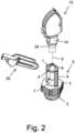
- Figs. 1-10 illustrate a first embodiment of a rotating sprinkler, generally indicated by numeral 10.
- Base component 5 has a retaining ring 6 which is in movable contact with an element of the lower coupling section 14 of head component 15 to maintain rotary movement of the head component about a vertical axis.
- Two mutually parallel upper plates 17 and 18 of head component 15 vertically extend above the lower coupling section 14, and a short post 19 extends perpendicularly and outwardly, i.e. in a direction away from the interspace between the two parallel plates, from a corresponding plate.
- Mounting arm 43 of gravitating hammer component 35 which is substantially parallel to plates 17 and 18, is coupled with a corresponding post 19 by an aperture 31 formed at a terminal end thereof, allowing gravitating hammer component 35 to pivot about a horizontal axis 29 passing through the two posts 19.
- a water stream is emitted from a discharge port 28, for example inverted U-shaped, which is formed in an interconnecting wall 32, e.g. planar, extending between a lower region of plates 17 and 18.
- retaining ring 6 of base component 5 is connected by a set of vertical posts 8, e.g. two diametrically opposite posts of a T-shaped cross section, to an underlying planar base 3, which may be one of the three vertically spaced bases, located above a threaded pipe fitting 4.
- a mounting tube 1 positioned centrally to retaining ring 6 projects from base 3 via an inverted frustoconical interface element 7 to a height above retaining ring 6, and its axis is the vertical axis 9 about which coupling section 14 of head component 15 rotates.
- Coupling section 14 may be configured with a lowermost annular frustoconical coupler 24 made of elastomeric material.
- the radial dimension of the lower portion 24b of the coupler is less than the radial clearance between retaining ring 6 and mounting tube 1 of base component 5 and the radial dimension of the upper thickened portion 24a of the coupler is significantly greater than the radial clearance, as shown in Fig. 3 , application of a downward force onto head component 15 causes compression of upper portion 24a, until the coupler is introduced between the vertical gap between retaining ring 6 and interface element 7.
- An audible clicking sound may be generated during compression of upper portion 24a as it applies a force to retaining ring 6, which may be formed with a dedicated circumferential gap 2 shown in Fig. 2 whose two ends may be forced together to cause the clicking sound when the compression-derived force is applied.
- Annular coupling section 14 also has a substantially horizontal surface 11 located above upper portion 24a of the coupler which is abuttable with retaining ring 6 to prevent unwanted vertical movement of head component 15, an upper throat portion 12 located directly above, and of a significantly smaller radial dimension than, surface 11, and short extension element 13 extending between horizontal surface 11 and the coupler and which is contactable by retaining ring 6.
- upper portion 24a expands and is able to contact the underside of retaining ring 6, to assist in resisting disengagement of coupling section 14 from retaining ring 6.
- the radially inner surface of the entire coupling section 14, including throat portion 12, horizontal surface 11, extension element 13 and coupler portions 24a-b is in movable contact with mounting tube 1, thus facilitating rotation of head component 15 while extension element 13 is retained within the annular space between mounting ring 1 and retaining ring 6.
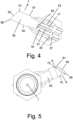
- each of the plates 17 and 18 of head component 15, i.e. opposite to the outward direction, is configured with an arcuate guide element 21, e.g. concave, for guiding the water discharged upwardly from mounting tube 1 along a channel to discharge port 28.
- the corresponding guide element 21 of plates 17 and 18 is in abutting relation with each other, as shown in Fig. 4 , and consequently confines the discharged water along a desired path.
- the wall of arcuate guide element 21 extends from a junction 27, e.g. a pointed junction, coinciding with bottom straight edge 26 of the plate to interconnecting wall 32, at a region thereof that is located above and adjoins discharge port 28.
- Junction 27 is spaced to the side of the upper end of mounting tube 1 to ensure that all the water discharged from mounting tube 1 will be directed to discharge port 28.
- Bottom straight edge 26 may be vertically spaced upwardly from the outlet of mounting tube 1.
- Each plate has an arcuate side edge 22 that follows the path of the gravitating hammer component as it pivots about axis 29 and a set of opposite differently angled straight side edges 23a-b.
- Arcuate side edge 22 extends upwardly and continuously from an upper region of planar interconnecting wall 32, at which it coincides with an upper straight edge 33 of guide element 21.
- Arcuate side edge 22 and straight side edge 23a coincide at summit 16, to define a plate having a height between summit 16 and bottom straight edge 26 that is approximately equal to 1.5 times its width between side edge 23a and interconnecting wall 32.
- a vertical reinforcing rib 37 that is integral with both plates 17 and 18 extends upwardly from upper straight edge 33 of guide element 21 to summit 16.
- a stopper element 34 for limiting the upward pivotal displacement of a corresponding mounting arm 43 of hammer component 35 extends slightly outwardly from the summit 16 of each plate.
- Head component 10 has a second, upwardly extending stopper 36 which is integral with interconnecting wall 32 and positioned slightly outwardly to discharge port 28, for limiting the downward pivotal displacement of a corresponding mounting arm 43.
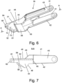
- hammer component 35 will now be described with reference to Figs. 4-8 . Since hammer component 35 is pivotable, it will be described as having first and second edges that are generally radially extending with respect to axis 29 about which the hammer component pivots. The first and second edges are referred to herein as being spaced “laterally”, or in a direction substantially perpendicular to the radial direction. “Distally” means in a lateral direction away from a post-receiving aperture 31, and “proximally” means in a lateral direction towards a post-receiving aperture 31.
- hammer component 35 comprises two spaced and elongated radially extending mounting arms 43 for pivotal mounting on a corresponding post 19 located close to a straight plate edge 23b, and two opposite and identical sidewall portions 44 extending continuously and forwardly, i.e. axially away from post-receiving aperture 31, from a corresponding mounting arm 43.
- a planar deflecting surface 52 for facilitating upward pivotal displacement of the hammer component is positioned between, projects forwardly from, and is aligned with, the first edge 46 of each sidewall portion 44. Deflecting surface 52 may terminate rearwardly at a discontinuity 45 between sidewall portion 44 and the corresponding mounting arm 43.
- a ramp 58 for directing the emitted water stream onto deflecting surface 52 is positioned between the second edge 47 of each sidewall portion 44.
- deflecting surface 52 has a non-rectangular configuration that has a forward edge 53 which is oblique with respect to its rearward laterally extending edge 54, as shown in Figs. 4-8 , such that a coincidence region 56 between forward edge 53 and side edge 55, which corresponds to and is spaced outwardly from plate 18, is spaced forwardly to coincidence region 61 between forward edge 53 and side edge 57, which corresponds to and is spaced outwardly from plate 17.
- a forward wall 62 for confining the deflected water is substantially perpendicular to deflecting surface 52, and extends distally from forward edge 53.
- Two sidewall portions 51 and 64 of a smaller lateral dimension than sidewall portion 44 are positioned forwardly thereto.
- Sidewall portion 51 is continuous with sidewall portion 44
- sidewall portion 44 is continuous with sidewall portion 64, the proximal edge of each sidewall portion coinciding one with the other.
- sidewall portion 51 is thin and its distal edge is substantially parallel to its proximal edge
- sidewall portion 64 is triangular, and its distal edge extends from the distal edge of sidewall portion 51 to the distal edge of coincidence region 56.
- the distal edge of coincidence regions 56 and 61, sidewall portion 64 and forward wall 62 may be coplanar.
- Two sloped surfaces 72 and 73 that may be spatially oriented with respect to deflecting surface 52 in different ways serve to direct the deflected water.
- the first side of triangular sloped surface 72 coincides with the distal edge of the sidewall portion 64 that is contiguous with coincidence region 56, the second side coincides with deflecting surface 52, and the third side coincides with elongated sloped surface 73.
- Elongated sloped surface 73 extends the entire length of forward wall 62.
- sidewall portion 44 may be distally, and also inwardly, offset from the corresponding mounting arm 43, and second distal edge 47 of sidewall 44 may be inclined with respect to first proximal edge 46 thereof, as shown more clearly in Fig. 7 .
- a convex edge 48 may interface between second edge 47 of sidewall portion 44 and second edge 42 of the corresponding mounting arm 43.
- An inclined edge 49, or alternatively a convex edge, may interface between first edge 46 of sidewall portion 44 and first edge 41 of the corresponding mounting arm 43.
- Ramp 58 has a thickened wall whose proximal ramped surface 59, clearly shown in Fig. 3 , may be disposed at a different angular orientation than second edge 47 of sidewall 44.
- Fig. 9 illustrates hammer component 35 when oriented at the lowermost pivoted position, following contact between distal edge 42 of each mounting arm 43 and the corresponding stopper 36 ( Fig. 1 ).
- Water W flowing through mounting tube 1 generally received from a water supply system, is discharged to upwardly and convexly curved channel 25 defined by guide element 21, and is consequently directed to discharge port 28, from which water stream WS is emitted.
- Hammer component 35 at the lowermost pivoted position intercepts water stream WS through the interior volume I between deflecting surface 52 and ramped surface 59.
- the intercepted water stream IWS is urged to flow upwardly along ramped surface 59 and to impinge upon deflecting surface 52 at a widthwise impingement region R forwardly to ramp 58, which may coincide with coincidence region 61.
- the force applied by the impinging water onto deflecting surface 52 has a component F that causes hammer component 35 to pivot upwardly.
- Water stream WS continues to be emitted while hammer component 35 is upwardly pivoting. Due to the change in orientation of ramped surface 59, intercepted water stream IWS impinges upon deflecting surface 52 at an impingement region R closer to mounting arm 43. The deflected water then flows downwardly along the inclined deflecting surface 52 and is discharged. Eventually hammer component 35 is significantly upwardly pivoted and interior volume I ceases to intercept water stream WS. Nevertheless water stream WS apples an upwardly directed force to ramp 58.
- Hammer component 35 therefore continues to be upwardly pivoted, through the influence of the upwardly directed force F and of inertia until assuming the extreme upwardly pivoted position shown in Fig. 10 at which proximal edge 41 of mounting arm 43 contacts stopper 34 ( Fig. 1 ).
- Water stream WS is shown to be continuously emitted through discharge port 28.
- hammer component 35 gravitates towards discharge port 28 in order to perform another cycle of water stream interception, transmission of a tangential force relative to the mounting tube to cause intermittent rotation of head component 15, and upwardly pivoted displacement.
- FIG. 11 A second embodiment of a rotating sprinkler 70 is illustrated in Fig. 11 .
- Sprinkler 70 comprises the same base component 5 and hammer component 35 as sprinkler 10 of Fig. 1 , as well as a head component 75 similar to head component 15 of Fig. 1 but configured with two convexly curved channels 71 and 74 defined by arcuate guide elements 72 and 76, respectively.
- Junction 77 e.g. a pointed junction, coinciding with bottom straight edge 26 of the plate 78 is located above the upper end of mounting tube 1 to ensure that all the water discharged from mounting tube 1 will be separated into two flows, a first flowing through channel 71 to discharge port 82 from which first water stream WS1 is emitted and a second flowing through channel 74 to discharge port 84 from which second water stream WS2 is emitted.
- Water stream WS2 is unaffected by hammer component 35, and therefore provides a uniform wetted area.
- the water distribution provided by water stream WS2 may be improved by stepped discontinuities 79 provided within channel 74.
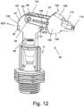
- FIG. 12-18 A third embodiment of a rotating sprinkler 90 is illustrated in Figs. 12-18 .
- sprinkler 90 comprises the same base component 5 as sprinkler 10 of Fig. 1 , as well as a head component 95 rotatably mounted on base component 5 having two mushroom shaped, mutually parallel and vertically oriented plates 97 and 98, and an invertable hammer component 105 configured with two oppositely oriented ramps 104 and 108, each of which extends inwardly between two mutually parallel and vertically oriented non-identical sidewalls 109 and 110.
- Each of plates 97 and 98 has a continuous arcuate upper edge 122 that subtends an angle of approximately 180 degrees.
- Each end of arcuate upper edge 122 extends upwardly and continuously from a corresponding upper region of opposite planar and vertically oriented interconnecting walls 126 and 127, each of which configured similarly to interconnecting wall 32 of Fig. 1 but formed with a corresponding rectangular discharge port 128; however, an inverted U-shaped discharge port may also be provided.
- Sprinkler 90 generates two water streams, a first water stream WS1 being emitted from the discharge port of interconnecting wall 126 and a second water stream WS2 being emitted from the discharge port of interconnecting wall 127.
- each of plates 97 and 98 Proximate to a summit 101 of each of plates 97 and 98 is provided a corresponding outwardly extending post 94, to which is rotatably mounted a corresponding mounting arm 43 of hammer component 105, allowing hammer component 105 to follow the curvature of upper edge 122 while pivoting.
- Each of plates 97 and 98 has a height between summit 101 and bottom straight edge 96 that is approximately equal to 1.2 times its width between interconnecting walls 126 and 127. Since the interconnecting walls 126 and 127 have an integral stopper 36, the downward pivotal displacement of hammer component 105 is limited in each rotational direction.
- Hammer component 105 when downwardly pivoted, is able to undergo a cycle of water stream interception, transmission of a tangential force relative to the mounting tube to cause intermittent rotation of head component 15, and upwardly pivoted displacement.
- hammer component 105 When hammer component 105 is upwardly pivoted to summit 101, it becomes inverted and is subsequently downwardly pivoted towards the other stopper 36.
- Each guide element confines the discharged water along a desired path.
- a reinforcing element 111 may extend upwardly from a terminal end of the corresponding guide element.
- Junction 107 is located above the upper end of mounting tube 1 to ensure that all the water discharged from mounting tube 1 will be separated into two flows, a first flowing through channel 101 to the discharge port of interconnecting wall 127 and a second flowing through channel 103 to the discharge port of interconnecting wall 126.
- proximal and distal directions relate to the orientation of hammer component 105 illustrated in Fig. 12 , whereby interconnecting wall 127 is positioned forwardly to interconnecting wall 126 and the forward edge 114 of hammer component 105 is positioned forwardly to interconnecting wall 127. It will be appreciated that the invention is similarly applicable when hammer component 105 is inverted following pivotal displacement whereby forward edge 114 is positioned forwardly to interconnecting wall 126 and interconnecting wall 126 is positioned forwardly to interconnecting wall 127.
- Hammer component 105 is configured with a planar deflecting surface 112 that is positioned inwardly between the two non-identical sidewalls 109 and 110.
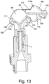
- Each of sidewalls 109 and 110 which is positioned forwardly to a corresponding mounting arm 43, has a rearward ramp-delimiting sidewall region 113, an intermediate sidewall region 116, and a forward sidewall region 118, as indicated in Fig. 14 .
- the two sidewall regions 113 are identical to each other, and deflecting surface 52 divides each sidewall region 113 into laterally symmetric sidewall portions 113a and 113b, as shown in Fig. 13 , such that ramps 104 and 108 protruding inwardly from sidewall region 113 are also laterally symmetric to each other.
- Each of sidewall portions 113a and 113b may be, but not necessarily, identical to sidewall portion 44 of Fig. 6 .
- intermediate sidewall region 116 may have a square-like configuration
- forward sidewall region 118 may have
- sidewall regions 116 and 118 of each sidewall 109 and 110 are of opposite lateral symmetry. That is, sidewall region 116 of sidewall 110 laterally extends only proximally from deflecting surface 112, while sidewall region 116 of sidewall 109 laterally extends only distally from deflecting surface 112. Also, sidewall region 118 of sidewall 110 laterally extends only distally from deflecting surface 112, while sidewall region 118 of sidewall 109 laterally extends only proximally from deflecting surface 112.
- An elongated guiding surface 133 extends obliquely from the forward edge of sidewall region 116 of sidewall 110 adjoining ramp 108 to a coincidence region between the sidewall region 118 of sidewall 109 and forward edge 114 of deflecting surface 112.
- a sloped surface 134 interfaces between the proximal edge of the sidewall region 118 of sidewall 109, deflecting surface 112 and guiding surface 133.
- the deflected water is urged to flow forcefully along elongated guiding surface 133 and along sloped surface 134, to exit hammer component 105 via the edge of the contiguous sidewall region 116 or 118 of sidewall 109.
- a reaction force T1 having a component that is opposite in direction to the direction of the exiting water and outwardly to sidewall 110 is produced, as shown in Fig. 17 , causing head component 95 to rotate a limited circumferential distance in a clockwise direction about mounting tube 1 when hammer component 105 is inverted with respect to the illustrated orientation.
- an elongated guiding surface 143 extends obliquely from the forward edge of sidewall region 116 of sidewall 109 adjoining ramp 104 to a coincidence region between the sidewall region 118 of sidewall 110 and forward edge 114 of deflecting surface 112.
- a sloped surface 144 interfaces between the distal edge of the sidewall region 118 of sidewall 110, deflecting surface 112 and guiding surface 143.
- the deflected water is urged to flow forcefully along elongated guiding surface 143 and along sloped surface 144, to exit hammer component 105 via the edge of the contiguous sidewall region 116 or 118 of sidewall 110.
- a reaction force T1 having a component that is opposite in direction to the direction of the exiting water and outwardly to sidewall 109 is produced, as shown in Fig. 18 , causing head component 95 to rotate a limited circumferential distance in a clockwise direction about mounting tube 1 with respect to the illustrated orientation. Accordingly, head component 95 is ensured of rotating in the same rotational direction irrespective of which interior space intercepts an emitted water stream.
Landscapes
- Nozzles (AREA)
Claims (4)
- Rotierender Impulsregner bzw. -sprinkler (10, 70, 90), umfassend:a) eine Basiskomponente (5), die an eine Wasserquelle bzw. -zufuhr angeschlossen ist;b) eine rotierende Kopfkomponente (15, 75, 95), aus der ein Wasserstrahl (WS, WS1, WS2) abgegeben wird und die drehbar auf einem vertikalen, rohrförmigen Element (1) der Basiskomponente montiert ist; undc) eine gravitierende Hammerkomponente (35, 105), die schwenkbar an der Kopfkomponente montiert ist und eine intermittierende Drehbewegung der Kopfkomponente um eine vertikale Drehachse bewirkt, indem sie intermittierend mit dem abgegebenen Strahl in Eingriff kommt und ansprechend darauf eine Reaktionskraft (T, T1) bereitstellt,wobei die gravitierende Hammerkomponente eine Ablenkfläche bzw. -oberfläche (52, 112) umfasst, auf die der abgegebene Strahl auftrifft, was die Hammerkomponente zum Schwenken veranlasst,wobei die gravitierende Hammerkomponente schwenkbar an einem oder mehreren horizontal ausgerichteten Montagelementen (19) der Kopfkomponente montierbar und um diese herum verschiebbar ist, wobei die Schwenkverschiebung der gravitierenden Hammerkomponente durch zwei beabstandete Stopper (34, 36) begrenzt ist, die von der Kopfkomponente vorstehen,wobei einer der beiden Stopper die gravitierende Hammerkomponente auf eine nach unten geschwenkte Position begrenzt, in der sie so konfiguriert ist, dass sie den abgegebenen Wasserstrom abfängt,wobei die Kopfkomponente mit einer Auslassöffnung (28, 82, 84, 128) und mit einem Kanal (25, 71, 74, 101, 103) konfiguriert ist, entlang dem Wasser (W) von der Wasserquelle fließen kann und durch die Auslassöffnung leitbar ist,dadurch gekennzeichnet, dass die gravitierende Hammerkomponente (35, 105) zudem eine Rampenfläche bzw. -oberfläche (59, 104, 108) umfasst, die schräg in Bezug auf die Ablenkfläche (52, 112) ausgerichtet ist, um einen Innenraum (I) zwischen der Ablenkfläche und der Rampenfläche zu definieren, wobei die gravitierende Hammerkomponente konfiguriert ist, den abgegebenen Wasserstrom (WS, WS1, WS2) innerhalb des Innenraums abzufangen, wenn sie nach unten geschwenkt ist, und den abgefangenen Wasserstrom (IWS) dazu zu drängen, entlang der Rampenfläche nach oben zu fließen und auf die Ablenkfläche aufzutreffen, was bewirkt, dass die Hammerkomponente nach oben schwenkt, bevor sie gravitiert wird,wobei Wasser (W) von der Wasserquelle entlang des Kanals (25, 71, 74) der gravitierenden Kopfkomponente (15, 75, 95) durch die Auslassöffnung (28, 82, 84) zu der Rampenfläche fließen kann und leitbar ist, wenn die gravitierende Hammerkomponente in der nach unten geschwenkten Position angeordnet ist, wobei die gravitierende Hammerkomponente mit einer oder mehreren Führungsflächen bzw. -oberflächen (72, 73, 133, 143) konfiguriert ist, die von der Ablenkfläche vorstehen und den abgefangenen Wasserstrom dazu drängen, entlang eines bestimmten Wegs vorwärts zu einem Auftreffbereich (R) zu flie-ßen, bis er aus der gravitierenden Hammerkomponente von dem Weg in einer Richtung austritt, die tangential zu dem röhrenförmigen Element ist, wobei eine Richtung der Reaktionskraft, die eine Rotation der Kopfkomponente verursacht, der Strömungsrichtung des austretenden Wassers entgegengesetzt ist.
- Rotierender Sprinkler nach Anspruch 1, wobei die gravitierende Hammerkomponente (35, 105) um mehr als 90 Grad in Bezug auf die nach unten geschwenkte Position schwenkbar ist, während die Kopfkomponente (15, 75, 95) in derselben Rotationsrichtung ungeachtet einer Ausrichtung der gravitierenden Hammerkomponente rotiert.
- Rotierender Sprinkler nach Anspruch 2, wobei die gravitierende Hammerkomponente (105) eine erste (104) und eine zweite (108) gegenüberliegend bzw. entgegengesetzt ausgerichtete Rampenflächen bzw.
-oberflächen umfasst und invertierbar ist, und wobei ein erster (133) und ein zweiter (143) Satz von Führungsflächen bzw. -oberflächen von gegenüberliegenden bzw. entgegengesetzten Flächen bzw. Seiten der Ablenkfläche (112) vorstehen, die so konfiguriert sind, dass sie den von der ersten bzw. zweiten Rampenfläche abgefangenen Wasserstrom (WS1, WS2) dazu drängen, entlang des bestimmten Wegs zu fließen. - Rotierender Sprinkler nach Anspruch 3, wobei die Kopfkomponente (95) mit einer ersten und einer zweiten gegenüberliegenden bzw. entgegengesetzten Auslassöffnung (128) und mit einem ersten (101) und einem zweiten (103) Kanal konfiguriert ist, durch die Wasser von der Wasserquelle geteilt wird und auf die erste und zweite Auslassöffnung bzw. auf die erste und zweite Rampenfläche gerichtet wird, wenn die gravitierende Hammerkomponente (105) an einer entsprechenden nach unten geschwenkten Position angeordnet ist.
Applications Claiming Priority (2)
| Application Number | Priority Date | Filing Date | Title |
|---|---|---|---|
| US201862762548P | 2018-05-09 | 2018-05-09 | |
| PCT/IL2019/050440 WO2019215716A1 (en) | 2018-05-09 | 2019-04-17 | Rotating sprinkler |
Publications (3)
| Publication Number | Publication Date |
|---|---|
| EP3790664A1 EP3790664A1 (de) | 2021-03-17 |
| EP3790664A4 EP3790664A4 (de) | 2022-02-23 |
| EP3790664B1 true EP3790664B1 (de) | 2024-01-03 |
Family
ID=68467315
Family Applications (1)
| Application Number | Title | Priority Date | Filing Date |
|---|---|---|---|
| EP19799595.4A Active EP3790664B1 (de) | 2018-05-09 | 2019-04-17 | Rotierender sprinkler |
Country Status (4)
| Country | Link |
|---|---|
| US (1) | US11305304B2 (de) |
| EP (1) | EP3790664B1 (de) |
| MA (1) | MA52583A (de) |
| WO (1) | WO2019215716A1 (de) |
Families Citing this family (2)
| Publication number | Priority date | Publication date | Assignee | Title |
|---|---|---|---|---|
| ES1254126Y (es) * | 2020-04-17 | 2021-01-11 | Das Tech Solutions S L U | Aplicadora modular de producto sobre material laminar |
| CN117815821B (zh) * | 2024-03-06 | 2024-05-28 | 江门市天誉通信技术工程有限公司 | 一种自动化建筑施工降尘装置 |
Family Cites Families (7)
| Publication number | Priority date | Publication date | Assignee | Title |
|---|---|---|---|---|
| US1593918A (en) | 1925-08-10 | 1926-07-27 | Stanton Lenthel | Sprinkler |
| US2708598A (en) * | 1952-02-11 | 1955-05-17 | Walter E Stary | Sprinklers |
| US2877053A (en) * | 1955-01-24 | 1959-03-10 | Kenneth F Kennard | Sprinkling devices |
| US3986671A (en) * | 1975-07-10 | 1976-10-19 | Robin Olivier Nugent | Spraying apparatus |
| US4235379A (en) | 1978-04-24 | 1980-11-25 | Rain Bird Sprinkler Mfg. Corp. | Interchangeable nozzle apparatus for full or part circle irrigation sprinklers |
| IL93824A (en) * | 1990-03-20 | 1997-02-18 | Rubinstein Zvi | Miniature water sprinkler protected against dirt and insects |
| DE102007012273A1 (de) * | 2007-03-07 | 2008-09-11 | Gardena Manufacturing Gmbh | Bewässerungsvorrichtung |
-
2019
- 2019-04-17 MA MA052583A patent/MA52583A/fr unknown
- 2019-04-17 US US17/051,228 patent/US11305304B2/en active Active
- 2019-04-17 WO PCT/IL2019/050440 patent/WO2019215716A1/en not_active Ceased
- 2019-04-17 EP EP19799595.4A patent/EP3790664B1/de active Active
Also Published As
| Publication number | Publication date |
|---|---|
| EP3790664A1 (de) | 2021-03-17 |
| WO2019215716A1 (en) | 2019-11-14 |
| US11305304B2 (en) | 2022-04-19 |
| US20210129163A1 (en) | 2021-05-06 |
| EP3790664A4 (de) | 2022-02-23 |
| MA52583A (fr) | 2021-03-17 |
Similar Documents
| Publication | Publication Date | Title |
|---|---|---|
| US9987639B2 (en) | Irrigation nozzle assembly and method | |
| EP1492626B1 (de) | Regner mit einstellbarem sprühbereich und einstellbarem durchfluss | |
| EP0761312B1 (de) | Kunststoff-Sprühdüse mit verbesserter Abgabe | |
| US5098021A (en) | Oscillatable nozzle sprinkler with integrated adjustable arc and flow | |
| US7044403B2 (en) | Rotary driven sprinkler with multiple nozzle ring | |
| EP3790664B1 (de) | Rotierender sprinkler | |
| US5104045A (en) | Sprinkler nozzle for uniform precipitation patterns | |
| US5544814A (en) | Rotary sprinklers | |
| US20060150899A1 (en) | Side and corner strip nozzle | |
| MX2011001376A (es) | Rociador. | |
| US4537356A (en) | Drive assembly for a reaction drive sprinkler | |
| CN112808473A (zh) | 一种出水装置及花洒 | |
| US4595141A (en) | Drive nozzle assembly for a reaction drive sprinkler | |
| US3955762A (en) | Rotatable sprinkler and water deflector used therewith | |
| US6076746A (en) | Strip irrigator | |
| EP1773503B1 (de) | Stossantriebssystem für sprinkler | |
| CN214811794U (zh) | 一种出水装置及花洒 | |
| CN113245086B (zh) | 喷头结构以及洒水装置 | |
| GB2242107A (en) | Rotary sprinkler | |
| US3820717A (en) | Flushable nozzle having means for redirecting and dispersing the effluent | |
| EP2651566B1 (de) | Deflektor für einen sprinkler | |
| JP2004057318A (ja) | 散布ヘッドの散布部構造 | |
| EP2193851A1 (de) | Stoßantriebssystem für Sprinkler |
Legal Events
| Date | Code | Title | Description |
|---|---|---|---|
| STAA | Information on the status of an ep patent application or granted ep patent |
Free format text: STATUS: THE INTERNATIONAL PUBLICATION HAS BEEN MADE |
|
| PUAI | Public reference made under article 153(3) epc to a published international application that has entered the european phase |
Free format text: ORIGINAL CODE: 0009012 |
|
| STAA | Information on the status of an ep patent application or granted ep patent |
Free format text: STATUS: REQUEST FOR EXAMINATION WAS MADE |
|
| 17P | Request for examination filed |
Effective date: 20201104 |
|
| AK | Designated contracting states |
Kind code of ref document: A1 Designated state(s): AL AT BE BG CH CY CZ DE DK EE ES FI FR GB GR HR HU IE IS IT LI LT LU LV MC MK MT NL NO PL PT RO RS SE SI SK SM TR |
|
| AX | Request for extension of the european patent |
Extension state: BA ME |
|
| DAX | Request for extension of the european patent (deleted) | ||
| RAV | Requested validation state of the european patent: fee paid |
Extension state: MA Effective date: 20201104 |
|
| A4 | Supplementary search report drawn up and despatched |
Effective date: 20220125 |
|
| RIC1 | Information provided on ipc code assigned before grant |
Ipc: B05B 3/00 20060101ALI20220119BHEP Ipc: B05B 3/04 20060101AFI20220119BHEP |
|
| STAA | Information on the status of an ep patent application or granted ep patent |
Free format text: STATUS: EXAMINATION IS IN PROGRESS |
|
| 17Q | First examination report despatched |
Effective date: 20221124 |
|
| GRAP | Despatch of communication of intention to grant a patent |
Free format text: ORIGINAL CODE: EPIDOSNIGR1 |
|
| STAA | Information on the status of an ep patent application or granted ep patent |
Free format text: STATUS: GRANT OF PATENT IS INTENDED |
|
| INTG | Intention to grant announced |
Effective date: 20230727 |
|
| GRAS | Grant fee paid |
Free format text: ORIGINAL CODE: EPIDOSNIGR3 |
|
| GRAA | (expected) grant |
Free format text: ORIGINAL CODE: 0009210 |
|
| STAA | Information on the status of an ep patent application or granted ep patent |
Free format text: STATUS: THE PATENT HAS BEEN GRANTED |
|
| P01 | Opt-out of the competence of the unified patent court (upc) registered |
Effective date: 20231110 |
|
| AK | Designated contracting states |
Kind code of ref document: B1 Designated state(s): AL AT BE BG CH CY CZ DE DK EE ES FI FR GB GR HR HU IE IS IT LI LT LU LV MC MK MT NL NO PL PT RO RS SE SI SK SM TR |
|
| REG | Reference to a national code |
Ref country code: GB Ref legal event code: FG4D |
|
| REG | Reference to a national code |
Ref country code: CH Ref legal event code: EP |
|
| REG | Reference to a national code |
Ref country code: DE Ref legal event code: R096 Ref document number: 602019044524 Country of ref document: DE |
|
| REG | Reference to a national code |
Ref country code: IE Ref legal event code: FG4D |
|
| REG | Reference to a national code |
Ref country code: LT Ref legal event code: MG9D |
|
| PG25 | Lapsed in a contracting state [announced via postgrant information from national office to epo] |
Ref country code: ES Free format text: LAPSE BECAUSE OF FAILURE TO SUBMIT A TRANSLATION OF THE DESCRIPTION OR TO PAY THE FEE WITHIN THE PRESCRIBED TIME-LIMIT Effective date: 20240103 |
|
| PG25 | Lapsed in a contracting state [announced via postgrant information from national office to epo] |
Ref country code: ES Free format text: LAPSE BECAUSE OF FAILURE TO SUBMIT A TRANSLATION OF THE DESCRIPTION OR TO PAY THE FEE WITHIN THE PRESCRIBED TIME-LIMIT Effective date: 20240103 |
|
| REG | Reference to a national code |
Ref country code: NL Ref legal event code: MP Effective date: 20240103 |
|
| REG | Reference to a national code |
Ref country code: AT Ref legal event code: MK05 Ref document number: 1646274 Country of ref document: AT Kind code of ref document: T Effective date: 20240103 |
|
| PG25 | Lapsed in a contracting state [announced via postgrant information from national office to epo] |
Ref country code: NL Free format text: LAPSE BECAUSE OF FAILURE TO SUBMIT A TRANSLATION OF THE DESCRIPTION OR TO PAY THE FEE WITHIN THE PRESCRIBED TIME-LIMIT Effective date: 20240103 |
|
| PG25 | Lapsed in a contracting state [announced via postgrant information from national office to epo] |
Ref country code: NL Free format text: LAPSE BECAUSE OF FAILURE TO SUBMIT A TRANSLATION OF THE DESCRIPTION OR TO PAY THE FEE WITHIN THE PRESCRIBED TIME-LIMIT Effective date: 20240103 |
|
| PG25 | Lapsed in a contracting state [announced via postgrant information from national office to epo] |
Ref country code: IS Free format text: LAPSE BECAUSE OF FAILURE TO SUBMIT A TRANSLATION OF THE DESCRIPTION OR TO PAY THE FEE WITHIN THE PRESCRIBED TIME-LIMIT Effective date: 20240503 |
|
| PG25 | Lapsed in a contracting state [announced via postgrant information from national office to epo] |
Ref country code: LT Free format text: LAPSE BECAUSE OF FAILURE TO SUBMIT A TRANSLATION OF THE DESCRIPTION OR TO PAY THE FEE WITHIN THE PRESCRIBED TIME-LIMIT Effective date: 20240103 |
|
| PG25 | Lapsed in a contracting state [announced via postgrant information from national office to epo] |
Ref country code: GR Free format text: LAPSE BECAUSE OF FAILURE TO SUBMIT A TRANSLATION OF THE DESCRIPTION OR TO PAY THE FEE WITHIN THE PRESCRIBED TIME-LIMIT Effective date: 20240404 |
|
| PG25 | Lapsed in a contracting state [announced via postgrant information from national office to epo] |
Ref country code: RS Free format text: LAPSE BECAUSE OF FAILURE TO SUBMIT A TRANSLATION OF THE DESCRIPTION OR TO PAY THE FEE WITHIN THE PRESCRIBED TIME-LIMIT Effective date: 20240403 Ref country code: HR Free format text: LAPSE BECAUSE OF FAILURE TO SUBMIT A TRANSLATION OF THE DESCRIPTION OR TO PAY THE FEE WITHIN THE PRESCRIBED TIME-LIMIT Effective date: 20240103 |
|
| PG25 | Lapsed in a contracting state [announced via postgrant information from national office to epo] |
Ref country code: CZ Free format text: LAPSE BECAUSE OF FAILURE TO SUBMIT A TRANSLATION OF THE DESCRIPTION OR TO PAY THE FEE WITHIN THE PRESCRIBED TIME-LIMIT Effective date: 20240103 Ref country code: AT Free format text: LAPSE BECAUSE OF FAILURE TO SUBMIT A TRANSLATION OF THE DESCRIPTION OR TO PAY THE FEE WITHIN THE PRESCRIBED TIME-LIMIT Effective date: 20240103 |
|
| PG25 | Lapsed in a contracting state [announced via postgrant information from national office to epo] |
Ref country code: RS Free format text: LAPSE BECAUSE OF FAILURE TO SUBMIT A TRANSLATION OF THE DESCRIPTION OR TO PAY THE FEE WITHIN THE PRESCRIBED TIME-LIMIT Effective date: 20240403 Ref country code: NO Free format text: LAPSE BECAUSE OF FAILURE TO SUBMIT A TRANSLATION OF THE DESCRIPTION OR TO PAY THE FEE WITHIN THE PRESCRIBED TIME-LIMIT Effective date: 20240403 Ref country code: LT Free format text: LAPSE BECAUSE OF FAILURE TO SUBMIT A TRANSLATION OF THE DESCRIPTION OR TO PAY THE FEE WITHIN THE PRESCRIBED TIME-LIMIT Effective date: 20240103 Ref country code: IS Free format text: LAPSE BECAUSE OF FAILURE TO SUBMIT A TRANSLATION OF THE DESCRIPTION OR TO PAY THE FEE WITHIN THE PRESCRIBED TIME-LIMIT Effective date: 20240503 Ref country code: HR Free format text: LAPSE BECAUSE OF FAILURE TO SUBMIT A TRANSLATION OF THE DESCRIPTION OR TO PAY THE FEE WITHIN THE PRESCRIBED TIME-LIMIT Effective date: 20240103 Ref country code: GR Free format text: LAPSE BECAUSE OF FAILURE TO SUBMIT A TRANSLATION OF THE DESCRIPTION OR TO PAY THE FEE WITHIN THE PRESCRIBED TIME-LIMIT Effective date: 20240404 Ref country code: CZ Free format text: LAPSE BECAUSE OF FAILURE TO SUBMIT A TRANSLATION OF THE DESCRIPTION OR TO PAY THE FEE WITHIN THE PRESCRIBED TIME-LIMIT Effective date: 20240103 Ref country code: BG Free format text: LAPSE BECAUSE OF FAILURE TO SUBMIT A TRANSLATION OF THE DESCRIPTION OR TO PAY THE FEE WITHIN THE PRESCRIBED TIME-LIMIT Effective date: 20240103 Ref country code: AT Free format text: LAPSE BECAUSE OF FAILURE TO SUBMIT A TRANSLATION OF THE DESCRIPTION OR TO PAY THE FEE WITHIN THE PRESCRIBED TIME-LIMIT Effective date: 20240103 |
|
| PG25 | Lapsed in a contracting state [announced via postgrant information from national office to epo] |
Ref country code: PT Free format text: LAPSE BECAUSE OF FAILURE TO SUBMIT A TRANSLATION OF THE DESCRIPTION OR TO PAY THE FEE WITHIN THE PRESCRIBED TIME-LIMIT Effective date: 20240503 Ref country code: PL Free format text: LAPSE BECAUSE OF FAILURE TO SUBMIT A TRANSLATION OF THE DESCRIPTION OR TO PAY THE FEE WITHIN THE PRESCRIBED TIME-LIMIT Effective date: 20240103 |
|
| PG25 | Lapsed in a contracting state [announced via postgrant information from national office to epo] |
Ref country code: SE Free format text: LAPSE BECAUSE OF FAILURE TO SUBMIT A TRANSLATION OF THE DESCRIPTION OR TO PAY THE FEE WITHIN THE PRESCRIBED TIME-LIMIT Effective date: 20240103 Ref country code: PT Free format text: LAPSE BECAUSE OF FAILURE TO SUBMIT A TRANSLATION OF THE DESCRIPTION OR TO PAY THE FEE WITHIN THE PRESCRIBED TIME-LIMIT Effective date: 20240503 Ref country code: PL Free format text: LAPSE BECAUSE OF FAILURE TO SUBMIT A TRANSLATION OF THE DESCRIPTION OR TO PAY THE FEE WITHIN THE PRESCRIBED TIME-LIMIT Effective date: 20240103 Ref country code: LV Free format text: LAPSE BECAUSE OF FAILURE TO SUBMIT A TRANSLATION OF THE DESCRIPTION OR TO PAY THE FEE WITHIN THE PRESCRIBED TIME-LIMIT Effective date: 20240103 |
|
| REG | Reference to a national code |
Ref country code: DE Ref legal event code: R097 Ref document number: 602019044524 Country of ref document: DE |
|
| PG25 | Lapsed in a contracting state [announced via postgrant information from national office to epo] |
Ref country code: DK Free format text: LAPSE BECAUSE OF FAILURE TO SUBMIT A TRANSLATION OF THE DESCRIPTION OR TO PAY THE FEE WITHIN THE PRESCRIBED TIME-LIMIT Effective date: 20240103 |
|
| PG25 | Lapsed in a contracting state [announced via postgrant information from national office to epo] |
Ref country code: SM Free format text: LAPSE BECAUSE OF FAILURE TO SUBMIT A TRANSLATION OF THE DESCRIPTION OR TO PAY THE FEE WITHIN THE PRESCRIBED TIME-LIMIT Effective date: 20240103 |
|
| PG25 | Lapsed in a contracting state [announced via postgrant information from national office to epo] |
Ref country code: EE Free format text: LAPSE BECAUSE OF FAILURE TO SUBMIT A TRANSLATION OF THE DESCRIPTION OR TO PAY THE FEE WITHIN THE PRESCRIBED TIME-LIMIT Effective date: 20240103 |
|
| PG25 | Lapsed in a contracting state [announced via postgrant information from national office to epo] |
Ref country code: SK Free format text: LAPSE BECAUSE OF FAILURE TO SUBMIT A TRANSLATION OF THE DESCRIPTION OR TO PAY THE FEE WITHIN THE PRESCRIBED TIME-LIMIT Effective date: 20240103 |
|
| PG25 | Lapsed in a contracting state [announced via postgrant information from national office to epo] |
Ref country code: SM Free format text: LAPSE BECAUSE OF FAILURE TO SUBMIT A TRANSLATION OF THE DESCRIPTION OR TO PAY THE FEE WITHIN THE PRESCRIBED TIME-LIMIT Effective date: 20240103 Ref country code: SK Free format text: LAPSE BECAUSE OF FAILURE TO SUBMIT A TRANSLATION OF THE DESCRIPTION OR TO PAY THE FEE WITHIN THE PRESCRIBED TIME-LIMIT Effective date: 20240103 Ref country code: RO Free format text: LAPSE BECAUSE OF FAILURE TO SUBMIT A TRANSLATION OF THE DESCRIPTION OR TO PAY THE FEE WITHIN THE PRESCRIBED TIME-LIMIT Effective date: 20240103 Ref country code: EE Free format text: LAPSE BECAUSE OF FAILURE TO SUBMIT A TRANSLATION OF THE DESCRIPTION OR TO PAY THE FEE WITHIN THE PRESCRIBED TIME-LIMIT Effective date: 20240103 Ref country code: DK Free format text: LAPSE BECAUSE OF FAILURE TO SUBMIT A TRANSLATION OF THE DESCRIPTION OR TO PAY THE FEE WITHIN THE PRESCRIBED TIME-LIMIT Effective date: 20240103 |
|
| REG | Reference to a national code |
Ref country code: DE Ref legal event code: R119 Ref document number: 602019044524 Country of ref document: DE |
|
| PLBE | No opposition filed within time limit |
Free format text: ORIGINAL CODE: 0009261 |
|
| STAA | Information on the status of an ep patent application or granted ep patent |
Free format text: STATUS: NO OPPOSITION FILED WITHIN TIME LIMIT |
|
| PG25 | Lapsed in a contracting state [announced via postgrant information from national office to epo] |
Ref country code: MC Free format text: LAPSE BECAUSE OF FAILURE TO SUBMIT A TRANSLATION OF THE DESCRIPTION OR TO PAY THE FEE WITHIN THE PRESCRIBED TIME-LIMIT Effective date: 20240103 |
|
| PG25 | Lapsed in a contracting state [announced via postgrant information from national office to epo] |
Ref country code: MC Free format text: LAPSE BECAUSE OF FAILURE TO SUBMIT A TRANSLATION OF THE DESCRIPTION OR TO PAY THE FEE WITHIN THE PRESCRIBED TIME-LIMIT Effective date: 20240103 |
|
| REG | Reference to a national code |
Ref country code: CH Ref legal event code: PL |
|
| PG25 | Lapsed in a contracting state [announced via postgrant information from national office to epo] |
Ref country code: IT Free format text: LAPSE BECAUSE OF FAILURE TO SUBMIT A TRANSLATION OF THE DESCRIPTION OR TO PAY THE FEE WITHIN THE PRESCRIBED TIME-LIMIT Effective date: 20240103 |
|
| 26N | No opposition filed |
Effective date: 20241007 |
|
| PG25 | Lapsed in a contracting state [announced via postgrant information from national office to epo] |
Ref country code: LU Free format text: LAPSE BECAUSE OF NON-PAYMENT OF DUE FEES Effective date: 20240417 |
|
| GBPC | Gb: european patent ceased through non-payment of renewal fee |
Effective date: 20240417 |
|
| REG | Reference to a national code |
Ref country code: BE Ref legal event code: MM Effective date: 20240430 |
|
| PG25 | Lapsed in a contracting state [announced via postgrant information from national office to epo] |
Ref country code: LU Free format text: LAPSE BECAUSE OF NON-PAYMENT OF DUE FEES Effective date: 20240417 Ref country code: IT Free format text: LAPSE BECAUSE OF FAILURE TO SUBMIT A TRANSLATION OF THE DESCRIPTION OR TO PAY THE FEE WITHIN THE PRESCRIBED TIME-LIMIT Effective date: 20240103 |
|
| PG25 | Lapsed in a contracting state [announced via postgrant information from national office to epo] |
Ref country code: DE Free format text: LAPSE BECAUSE OF NON-PAYMENT OF DUE FEES Effective date: 20241105 |
|
| PG25 | Lapsed in a contracting state [announced via postgrant information from national office to epo] |
Ref country code: BE Free format text: LAPSE BECAUSE OF NON-PAYMENT OF DUE FEES Effective date: 20240430 |
|
| PG25 | Lapsed in a contracting state [announced via postgrant information from national office to epo] |
Ref country code: GB Free format text: LAPSE BECAUSE OF NON-PAYMENT OF DUE FEES Effective date: 20240417 |
|
| PG25 | Lapsed in a contracting state [announced via postgrant information from national office to epo] |
Ref country code: FR Free format text: LAPSE BECAUSE OF NON-PAYMENT OF DUE FEES Effective date: 20240430 |
|
| PG25 | Lapsed in a contracting state [announced via postgrant information from national office to epo] |
Ref country code: GB Free format text: LAPSE BECAUSE OF NON-PAYMENT OF DUE FEES Effective date: 20240417 Ref country code: FR Free format text: LAPSE BECAUSE OF NON-PAYMENT OF DUE FEES Effective date: 20240430 Ref country code: DE Free format text: LAPSE BECAUSE OF NON-PAYMENT OF DUE FEES Effective date: 20241105 Ref country code: BE Free format text: LAPSE BECAUSE OF NON-PAYMENT OF DUE FEES Effective date: 20240430 Ref country code: CH Free format text: LAPSE BECAUSE OF NON-PAYMENT OF DUE FEES Effective date: 20240430 |
|
| PG25 | Lapsed in a contracting state [announced via postgrant information from national office to epo] |
Ref country code: IE Free format text: LAPSE BECAUSE OF NON-PAYMENT OF DUE FEES Effective date: 20240417 |
|
| PG25 | Lapsed in a contracting state [announced via postgrant information from national office to epo] |
Ref country code: SI Free format text: LAPSE BECAUSE OF FAILURE TO SUBMIT A TRANSLATION OF THE DESCRIPTION OR TO PAY THE FEE WITHIN THE PRESCRIBED TIME-LIMIT Effective date: 20240103 |
|
| PG25 | Lapsed in a contracting state [announced via postgrant information from national office to epo] |
Ref country code: CY Free format text: LAPSE BECAUSE OF FAILURE TO SUBMIT A TRANSLATION OF THE DESCRIPTION OR TO PAY THE FEE WITHIN THE PRESCRIBED TIME-LIMIT; INVALID AB INITIO Effective date: 20190417 |
|
| PG25 | Lapsed in a contracting state [announced via postgrant information from national office to epo] |
Ref country code: HU Free format text: LAPSE BECAUSE OF FAILURE TO SUBMIT A TRANSLATION OF THE DESCRIPTION OR TO PAY THE FEE WITHIN THE PRESCRIBED TIME-LIMIT; INVALID AB INITIO Effective date: 20190417 |
|
| PG25 | Lapsed in a contracting state [announced via postgrant information from national office to epo] |
Ref country code: FI Free format text: LAPSE BECAUSE OF FAILURE TO SUBMIT A TRANSLATION OF THE DESCRIPTION OR TO PAY THE FEE WITHIN THE PRESCRIBED TIME-LIMIT Effective date: 20240103 |
|
| VS25 | Lapsed in a validation state [announced via postgrant information from nat. office to epo] |
Ref country code: MA Free format text: FAILURE TO ELECT DOMICILE IN THE NATIONAL COUNTRY Effective date: 20240404 |