EP3790641B1 - Automatic cleaning of lamella plate settler - Google Patents
Automatic cleaning of lamella plate settler Download PDFInfo
- Publication number
- EP3790641B1 EP3790641B1 EP19800064.8A EP19800064A EP3790641B1 EP 3790641 B1 EP3790641 B1 EP 3790641B1 EP 19800064 A EP19800064 A EP 19800064A EP 3790641 B1 EP3790641 B1 EP 3790641B1
- Authority
- EP
- European Patent Office
- Prior art keywords
- cleaning
- lamella
- wheels
- cleaning system
- rails
- Prior art date
- Legal status (The legal status is an assumption and is not a legal conclusion. Google has not performed a legal analysis and makes no representation as to the accuracy of the status listed.)
- Active
Links
Images




Classifications
-
- B—PERFORMING OPERATIONS; TRANSPORTING
- B01—PHYSICAL OR CHEMICAL PROCESSES OR APPARATUS IN GENERAL
- B01D—SEPARATION
- B01D21/00—Separation of suspended solid particles from liquids by sedimentation
- B01D21/0006—Settling tanks provided with means for cleaning and maintenance
-
- B—PERFORMING OPERATIONS; TRANSPORTING
- B01—PHYSICAL OR CHEMICAL PROCESSES OR APPARATUS IN GENERAL
- B01D—SEPARATION
- B01D21/00—Separation of suspended solid particles from liquids by sedimentation
-
- B—PERFORMING OPERATIONS; TRANSPORTING
- B01—PHYSICAL OR CHEMICAL PROCESSES OR APPARATUS IN GENERAL
- B01D—SEPARATION
- B01D21/00—Separation of suspended solid particles from liquids by sedimentation
- B01D21/0039—Settling tanks provided with contact surfaces, e.g. baffles, particles
- B01D21/0045—Plurality of essentially parallel plates
-
- B—PERFORMING OPERATIONS; TRANSPORTING
- B01—PHYSICAL OR CHEMICAL PROCESSES OR APPARATUS IN GENERAL
- B01D—SEPARATION
- B01D21/00—Separation of suspended solid particles from liquids by sedimentation
- B01D21/30—Control equipment
-
- B—PERFORMING OPERATIONS; TRANSPORTING
- B08—CLEANING
- B08B—CLEANING IN GENERAL; PREVENTION OF FOULING IN GENERAL
- B08B1/00—Cleaning by methods involving the use of tools
- B08B1/10—Cleaning by methods involving the use of tools characterised by the type of cleaning tool
- B08B1/12—Brushes
-
- B—PERFORMING OPERATIONS; TRANSPORTING
- B08—CLEANING
- B08B—CLEANING IN GENERAL; PREVENTION OF FOULING IN GENERAL
- B08B1/00—Cleaning by methods involving the use of tools
- B08B1/30—Cleaning by methods involving the use of tools by movement of cleaning members over a surface
-
- B—PERFORMING OPERATIONS; TRANSPORTING
- B08—CLEANING
- B08B—CLEANING IN GENERAL; PREVENTION OF FOULING IN GENERAL
- B08B13/00—Accessories or details of general applicability for machines or apparatus for cleaning
-
- B—PERFORMING OPERATIONS; TRANSPORTING
- B01—PHYSICAL OR CHEMICAL PROCESSES OR APPARATUS IN GENERAL
- B01D—SEPARATION
- B01D21/00—Separation of suspended solid particles from liquids by sedimentation
- B01D21/0039—Settling tanks provided with contact surfaces, e.g. baffles, particles
-
- B—PERFORMING OPERATIONS; TRANSPORTING
- B01—PHYSICAL OR CHEMICAL PROCESSES OR APPARATUS IN GENERAL
- B01D—SEPARATION
- B01D21/00—Separation of suspended solid particles from liquids by sedimentation
- B01D21/0039—Settling tanks provided with contact surfaces, e.g. baffles, particles
- B01D21/0057—Settling tanks provided with contact surfaces, e.g. baffles, particles with counter-current flow direction of liquid and solid particles
Definitions
- the present invention relates generally to lamella plate settlers and more specifically to a system and a method for cleaning a lamella plate settler.
- a lamella plate settler is also provided.
- So called lamella plate settlers for water treatment applications are known.
- the feed in the form of liquid enters the basin through a feed pipe.
- the sludge In the hopper or on the bottom of the sedimentation basin, the sludge is thickened prior to discharge through a sludge outlet.
- the clarified liquid leaves the plate assembly through openings at the top and is discharged into collection channels leading to the clarified water outlet.
- a device for cleaning a lamella settler is disclosed in the patent publication No. US 1,458,805 A .
- a scraper device is disclosed which may be used in to prevent the building up of a cake on the settling surfaces in a settling tank.
- a set of scrapers may be used or a single scraper may be arranged to pass from one surface to another and to scrape all the settling surfaces successively at suitable intervals.
- Patent publication KR 100 969 933 B1 discloses a cleaning system for cleaning a lamella plate settler, wherein the system comprises a mechanical cleaning device supported in a frame. Movement is controlled by limit switches.
- Patent publication US 3 868 323 A discloses an apparatus for removal of settled or strained solids from surrounding liquid comprising means for lowering and raising a mechanical cleaning device in order to adapt to a bottom profile. No reference to lamella settlers is made.
- An object of the present invention is to provide a device and a method of cleaning a lamella plate settler which can be used automatically without interrupting the operation of the lamella plate settler.
- the invention is based on the realization that the lamella plates can be cleaned mechanically and automatically while the lamella plate settler is operating.
- a cleaning system for cleaning a lamella plate settler comprising at least one mechanical cleaning device; suspension means adapted to suspend the mechanical cleaning device; wherein the suspension means comprises displacement means for lowering and raising the at least one mechanical cleaning device for mechanical cleaning of a lamella plate positioned below the cleaning system, which is characterized by a frame supporting the at least one cleaning device; wheels attached to the frame and adapted to move on rails, the wheels comprising driving wheels, and a sensor, preferably an inductive sensor, adapted to sense the rotational position of the driving wheels.
- the wheels are adapted to run on rails.
- the driving wheels are designed as cogwheels adapted to move on rails provided with recesses or cut-outs at regular intervals, preferably intervals corresponding to the mutual distance between two adjacent lamella plates.
- the circumferential distance between two adjacent cogs of the driving wheels corresponds to the mutual distance between two adjacent lamella plates.
- non-driving wheels are provided to run on a planar surface.
- the at least one cleaning device comprises any of the following: a curtain, a cloth and a brush, preferably a tube provided with a brush material on the outside thereof.
- two mechanical cleaning devices are provided, preferably at a mutual longitudinal distance which corresponds to a multiple of the mutual distance between two adjacent lamella plates, and preferably being adapted to be lowered and raised simultaneously.
- the senor is adapted to sense a number of predetermined rotational positions of the driving wheels corresponding to a number of cogs on the driving wheels, these predetermined positions corresponding to positions of a cleaning operation.
- blocking means are adapted to shut of outlets for clean water from the basin adjacent to the lamella plate positioned below the cleaning system.
- two pairs of transverse wheels are provided which are adapted to move the system in a direction transverse to the direction of the first wheels.
- Each pair of transverse wheels is preferably mounted on an adjustable mount which is adapted to adjust the level of the transverse wheels between a first, upper position wherein the first wheels engage rails and a second, lower position wherein the first wheels are disengaged from rails.
- a lamella plate settler comprising a basin and a plurality of rows of lamella plates, the lamella plate settler being characterized by a pair of rails provided with recesses or cutouts at regular intervals, wherein one rail runs at one side of a row of lamella plates and another rail runs at the opposite side of the row of lamella plates with a mutual distance allowing the wheels of a cleaning system according to the invention to run on the rails.
- the rails are provided with a planar surface on which non-driving wheels of the cleaning system can run.
- a method of cleaning lamella plates of a lamella plate settler by means of a cleaning system which is characterized by the following steps: a) providing the cleaning system on rails above a lamella plate to be cleaned; b) lowering a mechanical cleaning device of the cleaning system into contact with the lamella plate to be cleaned; c) raising the mechanical cleaning device to a position above the lamella plate; d) displacing the mechanical cleaning device to another lamella plate to be cleaned; and e) repeating steps b) - d) until a last lamella plate is cleaned.
- the method of cleaning lamella plates of a lamella plate settler comprises the additional steps of moving the cleaning system by means of the transverse wheels from rails of a first row of a lamella plates to a second row of lamella plates and then repeating steps b) - d) until a last lamella plate of the second row of lamella plates has been cleaned.
- FIG. 1 This figure is a simplified drawing omitting parts, such as inlet and outlet for the fluid.
- the lamella plate settler generally designated 1, comprises a basin 10 which in a preferred embodiment is made of concrete. All or part of the basin 10 may be below the surface of the site, as indicated in the figure. There is an inlet for liquid to be cleaned in the end wall of the basin and a sludge outlet at the bottom of the basin (not shown). In one of the end walls there is a plurality of outlet openings 12 for cleaned liquid.
- a support structure in the form of plurality of transverse beams may be provided above the fluid contained in the basin 10, i.e., above the basin, or below the lamella.
- a plurality of outlet flumes 16 extend in the longitudinal direction of the basin 10. The outlet flumes 16 are supported in a suitable way, such as by means of threaded rods extending from beams.
- the flumes 16 are mutually parallel and thus form a space there between. Attached between adjacent flumes 16 are inclined lamella plates 18 forming lamella packages. If the lamella plates are made of plastic, adjacent lamella plates are interconnected by means of grooves provided in the edges of the lamella plates. If the lamella plates are made of stainless steel, they are preferably interconnected by means of riveting. These lamella plates, which preferably are made of plastic, are attached to the flumes 16 by means of riveting, for example.
- the system 20 comprises a housing, generally designated 22, resting on a frame 24.
- Two pairs of wheels 26 are attached to the frame 24 and are adapted to run on rails 19, such as U-beams, provided mutually parallel on the top of the lamella plate settler 1 and beside the rows of the lamella plates, including on the longitudinal walls of the basin 10.
- the wheels of the cleaning system 20 are driven by a motor, preferably an electric motor 28.
- a driving wheel on each side is designed as a cog wheel, as in the embodiment described with reference to Figs. 5A-C .
- the cleaning system 20 further comprises at least one brush and preferably two brushes, in the shown embodiment in the form of a first hollow tube 30 and a second hollow tube 32.
- These hollow tubes are on the outside provided with some kind of brush material suitable for the cleaning of the lamella plates 18.
- the hollow tubes 30, 32 are suspended by means of ropes 34, which run over a respective pulley 36 which are provided on a rod 38 provided perpendicularly to the direction of movement of the cleaning system 20.
- the ropes are guided by suspension rods 35 adapted to suspend the brushes 30, 32 at a predetermined mutual distance.
- a second servo motor 40 is provided at one end of the rod 38 to rotate the rod and therewith the pulleys in a controlled way.
- a lowered position for the brushes 30, 32 when they each is provided in a respective space formed between two adjacent lamella plates 18. From the position shown in Fig. 3 , they can be further lowered, as indicated by the arrows, to a position essentially at the lower edge of the lamella plates 18. This lowering is achieved by rotating the pulleys 36, in the shown figure counter-clockwise, synchronously.
- the two outlet flumes 16 adjacent to the row of lamella plates can be temporarily shut off by means of blocking members (not shown), such as boards, provided on the cleaning system 20. This shutting off can be fully automated.
- a single rope 34 runs via each pulley 36.
- the pulling force of the two brushes cancel out each other, which means that less power is needed for rotating the rod 38, which in turn means that the second servo motor can have less output power than if operating a single brush.
- a driving wheel on each side of this second embodiment is designed as a cog wheel, as in the embodiment described with reference to Figs. 5A and 5B .
- one of the wheels on either side namely a driving wheel 26'
- a driving wheel 26' is shaped like a cog wheel, which is adapted to move on rails 19 provided with recesses or cut-outs 19a at regular intervals. These intervals correspond to the mutual distance between two adjacent lamella plates 18, see Fig. 1 . The same distance is found in the circumferential distance between two adjacent cogs 26a' of the driving wheels 26'.
- at least one mechanical cleaning device in this embodiment two cleaning devices in the form of curtains 30 are provided at a mutual longitudinal distance which corresponds to a multiple of the mutual distance between two adjacent lamella plates.
- the driving wheels 26' are driven by a motor 28, either directly or indirectly, such as via a belt 29.
- a sensor 37 Adjacent to one of the driving wheels 26', a sensor 37, preferably an inductive sensor, is provided, which is connected to a control system adapted to control the turning of the driving wheels 26'.
- a simple, cost efficient and robust means is provided for determining the rotational position of the cleaning system 20 in relation to the lamella plates 18. For example, when one of the cogs 26a' of the driving wheels 26' is pointing downward, such as in Fig. 5B , the inductive sensor 37 is aligned with another one of the cogs 26a', which is detected by the sensor 37.
- the senor is adapted to sense a number of predetermined rotational positions of the driving wheels 26' corresponding to the number of cogs 26a'. These predetermined positions correspond to positions of a cleaning operation.
- a sensor is provided for detecting the recesses or cutouts in the rails which are provided at regular intervals, preferably intervals corresponding to the mutual distance between two adjacent lamella plates.
- Figs. 6A-C The operation cycle of the system for cleaning a lamella plate settler will now be described with reference to Figs. 6A-C .
- First the cleaning system is loaded on to the basin 10. This is achieved by first positioning a movable slope 50 against one of the side edges of the basin 10, see Fig. 1 .
- This slope may comprise two rails for guiding the cleaning system 20 or simply a planar surface.
- the system 20 is in itself not very heavy; two persons may carry or lift the system.
- the slope is aligned with the row of lamella plates 18 to be cleaned and so that the cleanings system 20 may be guided onto two adjacent rails 19.
- the cleaning system is then moved to a starting point.
- this is achieved by means of sensors, such as a limit switch which is mounted on the housing 23 and corresponding features on the rails 19, so that the cleaning system automatically can sense when this position has been reached.
- sensors such as a limit switch which is mounted on the housing 23 and corresponding features on the rails 19, so that the cleaning system automatically can sense when this position has been reached.
- the cleaning operation can start.
- the cleaning system will move forward upon pressing "Start Button" on an operation terminal or corresponding action.
- the control system of the cleaning system 20 When the inductive sensor 29 of the cleaning system 20 detects that the system is in a position for a cleaning operation, such as the position shown in Fig. 5B , the control system of the cleaning system 20 will send a signal to the drive motor 28 to stop.
- the cleaning operation described above with reference to Figs. 3 and 4a , 4b also applicable to the third embodiment, then commences.
- the brushes or curtains will be slowly submerged into the tank and moved along the lamella plates 18.
- the cleaning system 20 will move forward until it reaches the next cleaning position. In the example described with reference to Figs. 5A-C , this means that the driving wheels have turned another 1/7 th of a full turn. This cleaning operation is performed for seven times, after which in this example 14 lamella plates have been cleaned.
- the cleaning system 20 is then moved forward a distance corresponding to seven lamella plates, since these lamella plates have already been cleaned by the forward cleaning device.
- the next cycle starts with the cleaning of lamella plates 15 and 22.
- the repeated cleaning operation is then recommenced for another seven times etc.
- This special operation means that the cleaning device 20 moves backward a distance corresponding to a single mutual distance between two adjacent lamella plates 18, and a cleaning operation is performed after each such move.
- the cleaning system comprises a single cleaning device 30.
- the cleaning system is programmed to move a distance between each cleaning corresponding to a single distance between adjacent lamella plates.
- the cleaning of the lamella plate settler comprises a) providing a mechanical cleaning device above a lamella plate to be cleaned; b) lowering the mechanical cleaning device with the mechanical cleaning device in contact with the lamella plate to be cleaned; c) raising the mechanical cleaning device to a position above the lamella plate; d) displacing the mechanical cleaning device to another lamella plate to be cleaned; and repeating steps b) - d) until a last lamella plate to be cleaned.
- the operator can press a "Finish button” and the cleaning system will move out and give a space to put down the movable ramp, see Fig. 6B .
- an "End Process” button will be pressed and the cleaning system will automatically move backward along the ramp until the Limit Switch/Stop Sensor touches the end of the ramp, see Fig. 6C .
- FIG. 7 A fourth embodiment of a cleaning system for the lamella plate settler shown in Fig. 1 will now be described with reference to Figs. 7 and 8A , 8B .
- the system 20 is similar to the one shown in Fig. 5A but with the addition of transverse wheels 42, preferably two pairs thereof, which are adapted to move the system in a direction transverse to the direction of the other basic wheels 26, 26'.
- Each pair of transverse wheels is mounted on an adjustable mount 44 which is adapted to adjust the level of the transverse wheels between a first, upper position shown in Fig. 7 , wherein the first wheels 26, 26' engage rails and Fig. 8A , and a second, lower position shown in Fig. 8B , wherein the first wheels are disengaged from rails.
- the driving wheels are circular and preferably provided with a sensor (not shown) sensing the rotation of the driving wheels.
- a sensor is provided for detecting the recesses or cutouts in the rails which are provided at regular intervals, preferably intervals corresponding to the mutual distance between two adjacent lamella plates.
- transverse rails 46 extend in a direction transverse to the longitudinal rails 19 between adjacent rows of lamella plates. These transverse rails 46 are preferably provided at one end of the longitudinal rails 19, i.e. where the system for cleaning lamella plates has its start and end position, cf. Fig. 6A .
- the transverse wheels 42 are adjusted to their upper positions, lowering the wheels 26, 26' onto the adjacent pair of longitudinal rails. A cleaning operation as described above of the adjacent row of lamella plates can then commence.
- the cleanings devices have been shown as brushes. It will be realized that these cleaning devices can take any form suitable for mechanical cleaning of the lamella plates, such as cloths or curtains, such as in the third embodiment.
- rope has been used to describe part of the suspension of the brushes. It will be realized that this term also encompasses other elongated, flexible means, such as wires and chains.
- each brush is suspended by means of two ropes. It will be realized that a single rope is needed, but this will require guiding of the brush.
- both driving and non-driving wheels are provided. It will be appreciated that the non-driving wheels could be replaced by driving wheels to improve performance. Alternatively, also the non-driving wheels are designed as cog wheels.
Landscapes
- Chemical & Material Sciences (AREA)
- Chemical Kinetics & Catalysis (AREA)
- Cleaning In General (AREA)
- Extraction Or Liquid Replacement (AREA)
- Vehicle Cleaning, Maintenance, Repair, Refitting, And Outriggers (AREA)
Description
- The present invention relates generally to lamella plate settlers and more specifically to a system and a method for cleaning a lamella plate settler. A lamella plate settler is also provided.
- So called lamella plate settlers for water treatment applications are known. The feed in the form of liquid enters the basin through a feed pipe. As the liquid flows upward between inclined parallel plates, wherein solids settle on the inclined plates and slide down the plate. Once the sludge has fallen off the plate it will settle into a sludge hopper at the bottom of a free-standing unit or onto the bottom of the sedimentation basin. In the hopper or on the bottom of the sedimentation basin, the sludge is thickened prior to discharge through a sludge outlet. The clarified liquid leaves the plate assembly through openings at the top and is discharged into collection channels leading to the clarified water outlet.
- Even distribution of the flow to each plate ensures optimal operation at a high capacity. The side entry of the fluid prevents the solids that have settled from being carried away with the entering fluid.
- A prior art lamella plate settler is disclosed in the international publication No.
WO2015/167396A1 . - In lamella plate settlers, sludge and fat will accumulate on the plates. This will have a negative effect on the quality of the water leaving the basin. Therefore, there is a need for cleaning the plates at regular intervals, such as every 3-12 months of operation. Conventionally, this is done by emptying the basin of water and spraying the plates with high pressure water, either by means of a water hose or by means of high pressure water nozzles provided on a frame or the like. However, this cleaning results in an unwanted interruption in the operation of the lamella plate settler.
- A device for cleaning a lamella settler is disclosed in the patent publication No.
US 1,458,805 A . In this document, a scraper device is disclosed which may be used in to prevent the building up of a cake on the settling surfaces in a settling tank. A set of scrapers may be used or a single scraper may be arranged to pass from one surface to another and to scrape all the settling surfaces successively at suitable intervals. Patent publicationKR 100 969 933 B1 WO 2016/207459 A1 discloses a cleaning system for a lamella settler with a mechanical cleaning device supported by a frame. Movement of the frame is controlled by limit switches. Patent publicationUS 3 868 323 A discloses an apparatus for removal of settled or strained solids from surrounding liquid comprising means for lowering and raising a mechanical cleaning device in order to adapt to a bottom profile. No reference to lamella settlers is made. - An object of the present invention is to provide a device and a method of cleaning a lamella plate settler which can be used automatically without interrupting the operation of the lamella plate settler.
- The invention is based on the realization that the lamella plates can be cleaned mechanically and automatically while the lamella plate settler is operating.
- Thus, according to a first aspect of the invention there is provided a cleaning system for cleaning a lamella plate settler, comprising at least one mechanical cleaning device; suspension means adapted to suspend the mechanical cleaning device; wherein the suspension means comprises displacement means for lowering and raising the at least one mechanical cleaning device for mechanical cleaning of a lamella plate positioned below the cleaning system, which is characterized by a frame supporting the at least one cleaning device; wheels attached to the frame and adapted to move on rails, the wheels comprising driving wheels, and a sensor, preferably an inductive sensor, adapted to sense the rotational position of the driving wheels. In this way, a simple, cost efficient and robust means for automatic cleaning of a lamella plate settler is provided.
- In a preferred embodiment, the wheels are adapted to run on rails.
- In a preferred embodiment, the driving wheels are designed as cogwheels adapted to move on rails provided with recesses or cut-outs at regular intervals, preferably intervals corresponding to the mutual distance between two adjacent lamella plates.
- In a preferred embodiment, the circumferential distance between two adjacent cogs of the driving wheels corresponds to the mutual distance between two adjacent lamella plates.
- In a preferred embodiment, non-driving wheels are provided to run on a planar surface.
- In a preferred embodiment, the at least one cleaning device comprises any of the following: a curtain, a cloth and a brush, preferably a tube provided with a brush material on the outside thereof.
- In a preferred embodiment, two mechanical cleaning devices are provided, preferably at a mutual longitudinal distance which corresponds to a multiple of the mutual distance between two adjacent lamella plates, and preferably being adapted to be lowered and raised simultaneously.
- In a preferred embodiment, the sensor is adapted to sense a number of predetermined rotational positions of the driving wheels corresponding to a number of cogs on the driving wheels, these predetermined positions corresponding to positions of a cleaning operation.
- In a preferred embodiment, blocking means are adapted to shut of outlets for clean water from the basin adjacent to the lamella plate positioned below the cleaning system.
- In a preferred embodiment, two pairs of transverse wheels are provided which are adapted to move the system in a direction transverse to the direction of the first wheels. Each pair of transverse wheels is preferably mounted on an adjustable mount which is adapted to adjust the level of the transverse wheels between a first, upper position wherein the first wheels engage rails and a second, lower position wherein the first wheels are disengaged from rails.
- According to a second aspect of the invention, a lamella plate settler is provided comprising a basin and a plurality of rows of lamella plates, the lamella plate settler being characterized by a pair of rails provided with recesses or cutouts at regular intervals, wherein one rail runs at one side of a row of lamella plates and another rail runs at the opposite side of the row of lamella plates with a mutual distance allowing the wheels of a cleaning system according to the invention to run on the rails. Preferably, the rails are provided with a planar surface on which non-driving wheels of the cleaning system can run.
- According to a third aspect of the invention, a method of cleaning lamella plates of a lamella plate settler by means of a cleaning system according to the invention is provided which is characterized by the following steps: a) providing the cleaning system on rails above a lamella plate to be cleaned; b) lowering a mechanical cleaning device of the cleaning system into contact with the lamella plate to be cleaned; c) raising the mechanical cleaning device to a position above the lamella plate; d) displacing the mechanical cleaning device to another lamella plate to be cleaned; and e) repeating steps b) - d) until a last lamella plate is cleaned.
- In a preferred embodiment, the method of cleaning lamella plates of a lamella plate settler comprises the additional steps of moving the cleaning system by means of the transverse wheels from rails of a first row of a lamella plates to a second row of lamella plates and then repeating steps b) - d) until a last lamella plate of the second row of lamella plates has been cleaned.
- The invention is now described, by way of example, with reference to the accompanying drawings, in which:
-
Fig. 1 is a perspective view of a lamella plate settler, -
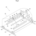
Fig. 2 is a perspective view, partly transparent, of a system for cleaning a lamella plate settler, -
Fig. 3 is a side view of a first embodiment of a system for cleaning a lamella plate settler according to the invention, -
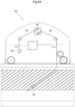
Figs. 4A and4B show side view of a second embodiment of a system for cleaning a lamella plate settler, -
Figs. 5A and 5B show a perspective view and a side view, respectively, of a third embodiment of a system for cleaning a lamella plate settler, whileFig. 5C shows the cross-sectional shape of rails on which the system runs, and -
Figs. 6A-C show schematic side views of different operation stages for a system for cleaning a lamella plate settler. -
Fig. 7 is a perspective view of a fourth embodiment of a system for cleaning a lamella plate settler. -
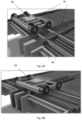
Figs. 8A and 8B show the system ofFig. 7 during operation in two different positions on rails on which the system runs. - In the following, a detailed description of a lamella plate settler used with a cleaning system and method according to the invention will be given with reference to
Fig. 1 . This figure is a simplified drawing omitting parts, such as inlet and outlet for the fluid. - The lamella plate settler, generally designated 1, comprises a
basin 10 which in a preferred embodiment is made of concrete. All or part of thebasin 10 may be below the surface of the site, as indicated in the figure. There is an inlet for liquid to be cleaned in the end wall of the basin and a sludge outlet at the bottom of the basin (not shown). In one of the end walls there is a plurality ofoutlet openings 12 for cleaned liquid. - A support structure in the form of plurality of transverse beams (not shown) may be provided above the fluid contained in the
basin 10, i.e., above the basin, or below the lamella. A plurality ofoutlet flumes 16 extend in the longitudinal direction of thebasin 10. The outlet flumes 16 are supported in a suitable way, such as by means of threaded rods extending from beams. - The
flumes 16 are mutually parallel and thus form a space there between. Attached betweenadjacent flumes 16 areinclined lamella plates 18 forming lamella packages. If the lamella plates are made of plastic, adjacent lamella plates are interconnected by means of grooves provided in the edges of the lamella plates. If the lamella plates are made of stainless steel, they are preferably interconnected by means of riveting. These lamella plates, which preferably are made of plastic, are attached to theflumes 16 by means of riveting, for example. - During operation, liquid flows upward between the inclined parallel plates, wherein solids settle on the inclined plates and slide down the plate. Once the sludge has fallen off the plate it will settle into a sludge hopper at the bottom of a free-standing unit or onto the bottom of the sedimentation basin. Since the lamella plates are supported from above, the space below them is free from any obstacles, simplifying removal of the sludge and thus improving the efficiency of the lamella plate settler.
- An overall view of a cleaning system for the lamella plate settler shown in
Fig. 1 will now be described with reference toFig. 2 . Thesystem 20 comprises a housing, generally designated 22, resting on aframe 24. Two pairs ofwheels 26 are attached to theframe 24 and are adapted to run onrails 19, such as U-beams, provided mutually parallel on the top of thelamella plate settler 1 and beside the rows of the lamella plates, including on the longitudinal walls of thebasin 10. The wheels of thecleaning system 20 are driven by a motor, preferably anelectric motor 28. Preferably, a driving wheel on each side is designed as a cog wheel, as in the embodiment described with reference toFigs. 5A-C . - The
cleaning system 20 further comprises at least one brush and preferably two brushes, in the shown embodiment in the form of a firsthollow tube 30 and a secondhollow tube 32. These hollow tubes are on the outside provided with some kind of brush material suitable for the cleaning of thelamella plates 18. Thehollow tubes ropes 34, which run over arespective pulley 36 which are provided on a rod 38 provided perpendicularly to the direction of movement of thecleaning system 20. The ropes are guided bysuspension rods 35 adapted to suspend thebrushes second servo motor 40 is provided at one end of the rod 38 to rotate the rod and therewith the pulleys in a controlled way. - The operation of the
rods Fig. 3 and inFigs. 4A ,4B , respectively. First with reference toFig. 3 , it is shown a lowered position for thebrushes adjacent lamella plates 18. From the position shown inFig. 3 , they can be further lowered, as indicated by the arrows, to a position essentially at the lower edge of thelamella plates 18. This lowering is achieved by rotating thepulleys 36, in the shown figure counter-clockwise, synchronously. - When the brushes have reached their lower end positions, the direction of rotation of the
pullies 36 is reversed, resulting in a raising of thebrushes lamella plates 18. The rope rewinding procedure will continue until the brushes touch a limit switch (not shown) at thehousing 22. During the process of lowering and raising thebrushes lamella plates 18, resulting in a mechanical cleaning thereof. - In order to avoid water containing particles stirred up by the cleaning operation from leaving the basin as cleaned water, the two
outlet flumes 16 adjacent to the row of lamella plates can be temporarily shut off by means of blocking members (not shown), such as boards, provided on thecleaning system 20. This shutting off can be fully automated. - In the second embodiment of a cleaning system shown with reference to
Figs. 4A and4B , onesingle rope 34 runs via eachpulley 36. This means that when one of thebrushes 30 is lowered during rotation of thepulley 36, inFig. 4A clockwise rotation, theother brush 32 is lowered. By providing a system like this, the pulling force of the two brushes cancel out each other, which means that less power is needed for rotating the rod 38, which in turn means that the second servo motor can have less output power than if operating a single brush. InFig. 4B , the reverse or counter-clockwise rotation of thepullies 36 is shown, resulting in the lowering of thefirst brush 30 and the raising of thesecond brush 32. Preferably, a driving wheel on each side of this second embodiment is designed as a cog wheel, as in the embodiment described with reference toFigs. 5A and 5B . - In a third embodiment of a cleaning system shown in
Figs. 5A-C , one of the wheels on either side, namely a driving wheel 26', is shaped like a cog wheel, which is adapted to move onrails 19 provided with recesses or cut-outs 19a at regular intervals. These intervals correspond to the mutual distance between twoadjacent lamella plates 18, seeFig. 1 . The same distance is found in the circumferential distance between two adjacent cogs 26a' of the driving wheels 26'. As in the other embodiments, at least one mechanical cleaning device, in this embodiment two cleaning devices in the form ofcurtains 30 are provided at a mutual longitudinal distance which corresponds to a multiple of the mutual distance between two adjacent lamella plates. The driving wheels 26' are driven by amotor 28, either directly or indirectly, such as via abelt 29. - Adjacent to one of the driving wheels 26', a
sensor 37, preferably an inductive sensor, is provided, which is connected to a control system adapted to control the turning of the driving wheels 26'. In this way, a simple, cost efficient and robust means is provided for determining the rotational position of thecleaning system 20 in relation to thelamella plates 18. For example, when one of the cogs 26a' of the driving wheels 26' is pointing downward, such as inFig. 5B , theinductive sensor 37 is aligned with another one of the cogs 26a', which is detected by thesensor 37. This corresponds to a position of thecleaning system 20 on therails 19 wherein thecleaning devices 30 are positioned above the space between twoadjacent lamella plates 18 and is thus a position wherein the cleaning devices can be lowered for a cleaning operation. In other words, in the preferred embodiments the sensor is adapted to sense a number of predetermined rotational positions of the driving wheels 26' corresponding to the number of cogs 26a'. These predetermined positions correspond to positions of a cleaning operation. - In order to allow also the
other wheels 26 to move on therails 19, these have an upside-down L shape, see the cross-sectional view ofFig. 5C . This means that the rails also have aplanar surface 19b on which theconventional rail wheels 26 can run. - Alternatively or additionally, a sensor is provided for detecting the recesses or cutouts in the rails which are provided at regular intervals, preferably intervals corresponding to the mutual distance between two adjacent lamella plates.
- The operation cycle of the system for cleaning a lamella plate settler will now be described with reference to
Figs. 6A-C . First the cleaning system is loaded on to thebasin 10. This is achieved by first positioning amovable slope 50 against one of the side edges of thebasin 10, seeFig. 1 . This slope may comprise two rails for guiding thecleaning system 20 or simply a planar surface. Thesystem 20 is in itself not very heavy; two persons may carry or lift the system. The slope is aligned with the row oflamella plates 18 to be cleaned and so that thecleanings system 20 may be guided onto twoadjacent rails 19. - The cleaning system is then moved to a starting point. In a preferred embodiment, this is achieved by means of sensors, such as a limit switch which is mounted on the housing 23 and corresponding features on the
rails 19, so that the cleaning system automatically can sense when this position has been reached. After the cleaning system has moved to its starting position, such as the one shown inFig. 6A , the cleaning operation can start. The cleaning system will move forward upon pressing "Start Button" on an operation terminal or corresponding action. - When the
inductive sensor 29 of thecleaning system 20 detects that the system is in a position for a cleaning operation, such as the position shown inFig. 5B , the control system of thecleaning system 20 will send a signal to thedrive motor 28 to stop. The cleaning operation described above with reference toFigs. 3 and4a ,4b , also applicable to the third embodiment, then commences. The brushes or curtains will be slowly submerged into the tank and moved along thelamella plates 18. - Once a cycle of cleaning of a lamella plate is completed the
cleaning system 20 will move forward until it reaches the next cleaning position. In the example described with reference toFigs. 5A-C , this means that the driving wheels have turned another 1/7th of a full turn. This cleaning operation is performed for seven times, after which in this example 14 lamella plates have been cleaned. Continuing the example with a mutual distance between the two cleaning devices of seven lamella plates, during the first cleaning operation cleanslamella plates 1 and 8, the second cleaning operation cleans lamella plates 2 and 9 etc. until lamella plates 7 and 14 have been cleaned. Thecleaning system 20 is then moved forward a distance corresponding to seven lamella plates, since these lamella plates have already been cleaned by the forward cleaning device. In the present example, the next cycle starts with the cleaning oflamella plates 15 and 22. The repeated cleaning operation is then recommenced for another seven times etc. - If, during this forward movement of seven lamella plates, the cleaning system reaches an end position, a special operations starts, since there are one or more lamella plates left uncleaned at the end of the basin. This special operation means that the
cleaning device 20 moves backward a distance corresponding to a single mutual distance between twoadjacent lamella plates 18, and a cleaning operation is performed after each such move. - This special operation is repeated until all remaining lamella plates have been cleaned and the
cleaning system 20 will move back to the starting position. - It will be appreciated that a similar control scheme can be applied if the cleaning system comprises a
single cleaning device 30. In that case, the cleaning system is programmed to move a distance between each cleaning corresponding to a single distance between adjacent lamella plates. - In summary, the cleaning of the lamella plate settler comprises a) providing a mechanical cleaning device above a lamella plate to be cleaned; b) lowering the mechanical cleaning device with the mechanical cleaning device in contact with the lamella plate to be cleaned; c) raising the mechanical cleaning device to a position above the lamella plate; d) displacing the mechanical cleaning device to another lamella plate to be cleaned; and repeating steps b) - d) until a last lamella plate to be cleaned.
- Upon arriving at the starting position, the operator can press a "Finish button" and the cleaning system will move out and give a space to put down the movable ramp, see
Fig. 6B . When the movable ramp is in place, an "End Process" button will be pressed and the cleaning system will automatically move backward along the ramp until the Limit Switch/Stop Sensor touches the end of the ramp, seeFig. 6C . - After that the
cleaning system 20 has run up the slope and to the position shown inFig. 6C , themovable slope 50 will be taken away. - A fourth embodiment of a cleaning system for the lamella plate settler shown in
Fig. 1 will now be described with reference toFigs. 7 and8A ,8B . Thesystem 20 is similar to the one shown inFig. 5A but with the addition oftransverse wheels 42, preferably two pairs thereof, which are adapted to move the system in a direction transverse to the direction of the otherbasic wheels 26, 26'. Each pair of transverse wheels is mounted on anadjustable mount 44 which is adapted to adjust the level of the transverse wheels between a first, upper position shown inFig. 7 , wherein thefirst wheels 26, 26' engage rails andFig. 8A , and a second, lower position shown inFig. 8B , wherein the first wheels are disengaged from rails. - In the embodiment of
Fig. 8A , the driving wheels are circular and preferably provided with a sensor (not shown) sensing the rotation of the driving wheels. Alternatively or additionally, a sensor is provided for detecting the recesses or cutouts in the rails which are provided at regular intervals, preferably intervals corresponding to the mutual distance between two adjacent lamella plates. - Turning now to
Figs. 8A and 8B , the function of thetransverse wheels 42 will be explained. In addition to thelongitudinal rails 19,transverse rails 46 extend in a direction transverse to thelongitudinal rails 19 between adjacent rows of lamella plates. Thesetransverse rails 46 are preferably provided at one end of thelongitudinal rails 19, i.e. where the system for cleaning lamella plates has its start and end position, cf.Fig. 6A . - The operation of the fourth embodiment will now be described. When the
system 20 is in the end position shown inFig. 8A , this is detected by means of sensors (not shown). The transverse wheels are then lowered to the level shown inFig. 8B , which means that thebasic wheels 26, 26' are lifted from the longitudinal rails 19. By means of thetransverse wheels 42, thesystem 20 is moved from one pair oflongitudinal rails 19, seeFig. 8A , to an adjacent pair of longitudinal rails, seeFig. 8B while thetransverse wheels 42 run on the transverse rails 46. InFig. 8B , thesystem 20 has been moved half way between adjacent pairs of longitudinal rails by means of thetransverse wheels 42. - When the
system 20 has reached the adjacent pair of longitudinal rails, thetransverse wheels 42 are adjusted to their upper positions, lowering thewheels 26, 26' onto the adjacent pair of longitudinal rails. A cleaning operation as described above of the adjacent row of lamella plates can then commence. - This means that two or more rows of lamella plates can be automatically cleaned without interruption or operation by operators.
- Preferred embodiments of a system for cleaning a lamella plate settler according to the invention have been described. It will be realized that these can be varied within the scope of the appended claims. Also, instead of providing fixed rails on the basin, removable rails may be provided, which are positioned on desired positions on the basin in order to allow movement of the system thereon.
- A purely mechanical cleaning system has been described. It will be realized that this may be supplemented with spray nozzles to enable spray cleaning of the lamella plates as well.
- The cleanings devices have been shown as brushes. It will be realized that these cleaning devices can take any form suitable for mechanical cleaning of the lamella plates, such as cloths or curtains, such as in the third embodiment.
- The term "rope" has been used to describe part of the suspension of the brushes. It will be realized that this term also encompasses other elongated, flexible means, such as wires and chains.
- In the shown embodiments, there are two brushes. It will be realized that also a single brush can be provided, simplifying the system but making cleaning of a plurality of lamella plates slower.
- Also, each brush is suspended by means of two ropes. It will be realized that a single rope is needed, but this will require guiding of the brush.
- In the embodiments, both driving and non-driving wheels are provided. It will be appreciated that the non-driving wheels could be replaced by driving wheels to improve performance. Alternatively, also the non-driving wheels are designed as cog wheels.
Claims (12)
- A cleaning system (20) for cleaning a lamella plate settler (1), comprisingat least one mechanical cleaning device (30);suspension means (34, 35, 36, 40) adapted to suspend the mechanical cleaning device (30);wherein the suspension means comprises displacement means (36, 40) for lowering and raising the at least one mechanical cleaning device (30) for mechanical cleaning of a lamella plate (18) positioned below the cleaning system (20),characterized bya frame (24) supporting the at least one cleaning device (30);wheels (26, 26') attached to the frame and adapted to move on rails (19), the wheels comprising driving wheels (26'),a sensor (37), preferably an inductive sensor, adapted to sense the rotational position of the driving wheels (26'),further the sensor (37) is connected to a control system, which control system is adapted to control: the turning of the wheels (26'), the movement of the cleaning system (20) between different cleaning positions and the initiation of lowering and raising of the at least one mechanical cleaning device (30).
- The cleaning system (20) according to claim 1, wherein the wheels (26, 26') are adapted to run on rails.
- The cleaning system (20) according to claim 2, wherein the driving wheels (26') are designed as cog wheels adapted to move on rails (19) provided with recesses or cut-outs (19a) at regular intervals, preferably intervals corresponding to the mutual distance between two adjacent lamella plates (18).
- The cleaning system (20) according to any one of claims 1-3, wherein the circumferential distance between two adjacent cogs (26a') of the driving wheels (26') corresponds to the mutual distance between two adjacent lamella plates (18).
- The cleaning system (20) according to any one of claims 1-4, comprising non-driving wheels (26) adapted to run on a planar surface (19b) of a rail.
- The cleaning system (20) according to any one of claims 1-5, wherein the at least one cleaning device (30) comprises any of the following: a curtain, a cloth and a brush, preferably a tube provided with a brush material on the outside thereof.
- The cleaning system (20) according to any one of claims 1-6, comprising two mechanical cleaning devices (30), preferably provided at a mutual longitudinal distance which corresponds to a multiple of the mutual distance between two adjacent lamella plates, and preferably being adapted to be lowered and raised simultaneously.
- The cleaning system (20) according to any one of claims 1-7, wherein the sensor (37) is adapted to sense a number of predetermined rotational positions of the driving wheels (26') corresponding to a number of cogs (26a') on the driving wheels (26'), these predetermined positions corresponding to positions of a cleaning operation.
- The cleaning system (20) according to any one of claims 1-8, comprising two pairs of transverse wheels (42) which are adapted to move the system in a direction transverse to the direction of the first wheels (26, 26').
- The cleaning system (20) according to claim 9, wherein each pair of transverse wheels is mounted on an adjustable mount (44) which is adapted to adjust the level of the transverse wheels between a first, upper position wherein the first wheels (26, 26') engage rails and a second, lower position wherein the first wheels (26, 26') are disengaged from rails.
- A method of cleaning lamella plates of a lamella plate settler (1) by means of a cleaning system (20) according to any one of claims 1-10, characterized by the following steps:a) providing the cleaning system (20) on rails (19) above a lamella plate (18) to be cleaned;b) lowering a mechanical cleaning device (30) of the cleaning system (20) into contact with the lamella plate (18) to be cleaned;c) raising the mechanical cleaning device (30) to a position above the lamella plate (18);d) displacing the mechanical cleaning device (30) by means of the cleaning system (20) on the rails (19) by the driving wheels (26') and by means of a control system adapted to control the turning of the driving wheels (26'), to another lamella plate (18) to be cleaned; ande) repeating steps b) - d) until a last lamella plate is cleaned.
- The method of cleaning lamella plates of a lamella plate settler (1) according to claim 11 by means of a cleaning system (20) according to any one of claims 9 and 10, comprising the additional steps of moving the cleaning system (20) by means of the transverse wheels (42) from rails of a first row of a lamella plates (18) to a second row of lamella plates and then repeating steps b) - d) until a last lamella plate of the second row of lamella plates has been cleaned. --
Applications Claiming Priority (2)
| Application Number | Priority Date | Filing Date | Title |
|---|---|---|---|
| SE1850551A SE542367C2 (en) | 2018-05-09 | 2018-05-09 | Automatic cleaning of lamella plate settler |
| PCT/SE2019/050410 WO2019216814A1 (en) | 2018-05-09 | 2019-05-08 | Automatic cleaning of lamella plate settler |
Publications (3)
| Publication Number | Publication Date |
|---|---|
| EP3790641A1 EP3790641A1 (en) | 2021-03-17 |
| EP3790641A4 EP3790641A4 (en) | 2021-06-30 |
| EP3790641B1 true EP3790641B1 (en) | 2023-07-05 |
Family
ID=68467472
Family Applications (1)
| Application Number | Title | Priority Date | Filing Date |
|---|---|---|---|
| EP19800064.8A Active EP3790641B1 (en) | 2018-05-09 | 2019-05-08 | Automatic cleaning of lamella plate settler |
Country Status (6)
| Country | Link |
|---|---|
| US (1) | US11679344B2 (en) |
| EP (1) | EP3790641B1 (en) |
| ES (1) | ES2955233T3 (en) |
| SE (1) | SE542367C2 (en) |
| SG (1) | SG11202010912UA (en) |
| WO (1) | WO2019216814A1 (en) |
Families Citing this family (1)
| Publication number | Priority date | Publication date | Assignee | Title |
|---|---|---|---|---|
| FR3166080A1 (en) * | 2024-09-11 | 2026-03-13 | Leon | Bladed Pergola Cleaning Robot |
Family Cites Families (10)
| Publication number | Priority date | Publication date | Assignee | Title |
|---|---|---|---|---|
| US1458805A (en) * | 1920-12-13 | 1923-06-12 | Niels C Christensen | Apparatus for the settlement of solid particles suspended in liquids |
| IT993760B (en) * | 1972-09-06 | 1975-09-30 | Prometall Uznach Ag | EXTRACTION DEVICE FOR CLARIFICATION AND SEWERING SYSTEMS |
| JPS5579012A (en) * | 1978-12-07 | 1980-06-14 | Yoshitomo Maru | Running type scraping machine for precipitate |
| SE502455C2 (en) * | 1994-03-07 | 1995-10-23 | Kenneth Winde Ab | Method and apparatus for cleaning slats in a slat separator |
| KR100969933B1 (en) * | 2010-01-07 | 2010-07-14 | 뮤러아시아(주) | Inclined lamella clarifier having washing device for settling tank |
| KR101931365B1 (en) * | 2011-08-22 | 2018-12-24 | 삼성전자주식회사 | Robot cleaner and method for controlling the same |
| ES2594865B1 (en) * | 2015-06-23 | 2017-10-11 | Pedro Roberto RODRÍGUEZ GÓMEZ | CLEANING SYSTEM TO AUTOMATICALLY CLEAN A TANK OF A LAMELAR DECANT AND LAMELAR DECANTOR THAT INCLUDES SUCH CLEANING SYSTEM |
| CN207237380U (en) * | 2017-09-26 | 2018-04-17 | 贵州水投水务集团有限公司 | It is a kind of can high-efficiency washing inclined-tube sedimentation tank device |
| CN207545903U (en) * | 2017-12-05 | 2018-06-29 | 蒋希任 | A kind of high frequency inclined tube mud cleaning machine |
| CN208440340U (en) | 2018-04-23 | 2019-01-29 | 嘉兴市锦福缩染有限公司 | Mud-scraping apparatus for sedimentation basin |
-
2018
- 2018-05-09 SE SE1850551A patent/SE542367C2/en unknown
-
2019
- 2019-05-08 SG SG11202010912UA patent/SG11202010912UA/en unknown
- 2019-05-08 WO PCT/SE2019/050410 patent/WO2019216814A1/en not_active Ceased
- 2019-05-08 EP EP19800064.8A patent/EP3790641B1/en active Active
- 2019-05-08 ES ES19800064T patent/ES2955233T3/en active Active
- 2019-05-08 US US17/052,566 patent/US11679344B2/en active Active
Also Published As
| Publication number | Publication date |
|---|---|
| EP3790641A4 (en) | 2021-06-30 |
| SG11202010912UA (en) | 2020-12-30 |
| WO2019216814A1 (en) | 2019-11-14 |
| SE542367C2 (en) | 2020-04-14 |
| ES2955233T3 (en) | 2023-11-29 |
| SE1850551A1 (en) | 2019-11-10 |
| US20210236962A1 (en) | 2021-08-05 |
| US11679344B2 (en) | 2023-06-20 |
| EP3790641A1 (en) | 2021-03-17 |
Similar Documents
| Publication | Publication Date | Title |
|---|---|---|
| US4514303A (en) | Sludge traction and desludging system | |
| KR101016488B1 (en) | Sludge / Scum Removal Device | |
| KR102161407B1 (en) | Screen trash removal equipment | |
| US4193871A (en) | Clarifier | |
| US20050139557A1 (en) | Tertiary filter | |
| CN117142570A (en) | Sewage treatment equipment convenient for separating sundries | |
| US11679344B2 (en) | Automatic cleaning of lamella plate settler | |
| CN106799073B (en) | A kind of catch basin with cleaning function | |
| CN113830967B (en) | Zero-dosing treatment method for high-concentration wastewater | |
| CN220802043U (en) | Cleaning device for inclined tube of high-density pool | |
| CN112495013B (en) | Automatic scraping device for filter cake of filter press | |
| CN219279579U (en) | Intelligent oil removal device | |
| HK40038475A (en) | Automatic cleaning of lamella plate settler | |
| HK40038475B (en) | Automatic cleaning of lamella plate settler | |
| KR100908699B1 (en) | Wastewater Treatment System of Oil Separation Tank | |
| CN215781712U (en) | Sewage treatment system and automatic cleaning system for effluent weir plate thereof | |
| CN117837778B (en) | Raw material cleaning equipment and application thereof in seafood sauce production | |
| CN112190982B (en) | High-efficient non-maintaining swash plate subsides device | |
| RU2774239C2 (en) | Automatic cleaning of a thin-plate settling tank | |
| CN215559091U (en) | Floater and suspended solid cleaning device for coarse grating | |
| US12583762B2 (en) | Screening device for use in coarse matter screening wells of a waste water treatment plant | |
| KR100755258B1 (en) | Automatic Reciprocating Sludge Collector | |
| JP3924557B2 (en) | Sludge recovery equipment | |
| CN116832522A (en) | Magnetic filter removes fatlute device | |
| CN220405010U (en) | Multistage filtering device for environment-friendly sewage treatment |
Legal Events
| Date | Code | Title | Description |
|---|---|---|---|
| STAA | Information on the status of an ep patent application or granted ep patent |
Free format text: STATUS: THE INTERNATIONAL PUBLICATION HAS BEEN MADE |
|
| PUAI | Public reference made under article 153(3) epc to a published international application that has entered the european phase |
Free format text: ORIGINAL CODE: 0009012 |
|
| STAA | Information on the status of an ep patent application or granted ep patent |
Free format text: STATUS: REQUEST FOR EXAMINATION WAS MADE |
|
| 17P | Request for examination filed |
Effective date: 20201110 |
|
| AK | Designated contracting states |
Kind code of ref document: A1 Designated state(s): AL AT BE BG CH CY CZ DE DK EE ES FI FR GB GR HR HU IE IS IT LI LT LU LV MC MK MT NL NO PL PT RO RS SE SI SK SM TR |
|
| AX | Request for extension of the european patent |
Extension state: BA ME |
|
| REG | Reference to a national code |
Ref country code: HK Ref legal event code: DE Ref document number: 40038475 Country of ref document: HK |
|
| A4 | Supplementary search report drawn up and despatched |
Effective date: 20210601 |
|
| RIC1 | Information provided on ipc code assigned before grant |
Ipc: B01D 21/00 20060101AFI20210526BHEP Ipc: B01D 21/30 20060101ALI20210526BHEP |
|
| DAV | Request for validation of the european patent (deleted) | ||
| DAX | Request for extension of the european patent (deleted) | ||
| RAP1 | Party data changed (applicant data changed or rights of an application transferred) |
Owner name: SULZER MANAGEMENT AG |
|
| GRAP | Despatch of communication of intention to grant a patent |
Free format text: ORIGINAL CODE: EPIDOSNIGR1 |
|
| STAA | Information on the status of an ep patent application or granted ep patent |
Free format text: STATUS: GRANT OF PATENT IS INTENDED |
|
| INTG | Intention to grant announced |
Effective date: 20230322 |
|
| GRAS | Grant fee paid |
Free format text: ORIGINAL CODE: EPIDOSNIGR3 |
|
| GRAA | (expected) grant |
Free format text: ORIGINAL CODE: 0009210 |
|
| STAA | Information on the status of an ep patent application or granted ep patent |
Free format text: STATUS: THE PATENT HAS BEEN GRANTED |
|
| P01 | Opt-out of the competence of the unified patent court (upc) registered |
Effective date: 20230412 |
|
| AK | Designated contracting states |
Kind code of ref document: B1 Designated state(s): AL AT BE BG CH CY CZ DE DK EE ES FI FR GB GR HR HU IE IS IT LI LT LU LV MC MK MT NL NO PL PT RO RS SE SI SK SM TR |
|
| REG | Reference to a national code |
Ref country code: CH Ref legal event code: EP |
|
| REG | Reference to a national code |
Ref country code: AT Ref legal event code: REF Ref document number: 1584298 Country of ref document: AT Kind code of ref document: T Effective date: 20230715 |
|
| REG | Reference to a national code |
Ref country code: DE Ref legal event code: R096 Ref document number: 602019032246 Country of ref document: DE |
|
| REG | Reference to a national code |
Ref country code: IE Ref legal event code: FG4D |
|
| REG | Reference to a national code |
Ref country code: SE Ref legal event code: TRGR |
|
| REG | Reference to a national code |
Ref country code: LT Ref legal event code: MG9D |
|
| REG | Reference to a national code |
Ref country code: NL Ref legal event code: MP Effective date: 20230705 |
|
| REG | Reference to a national code |
Ref country code: ES Ref legal event code: FG2A Ref document number: 2955233 Country of ref document: ES Kind code of ref document: T3 Effective date: 20231129 |
|
| REG | Reference to a national code |
Ref country code: AT Ref legal event code: MK05 Ref document number: 1584298 Country of ref document: AT Kind code of ref document: T Effective date: 20230705 |
|
| PG25 | Lapsed in a contracting state [announced via postgrant information from national office to epo] |
Ref country code: NL Free format text: LAPSE BECAUSE OF FAILURE TO SUBMIT A TRANSLATION OF THE DESCRIPTION OR TO PAY THE FEE WITHIN THE PRESCRIBED TIME-LIMIT Effective date: 20230705 |
|
| PG25 | Lapsed in a contracting state [announced via postgrant information from national office to epo] |
Ref country code: GR Free format text: LAPSE BECAUSE OF FAILURE TO SUBMIT A TRANSLATION OF THE DESCRIPTION OR TO PAY THE FEE WITHIN THE PRESCRIBED TIME-LIMIT Effective date: 20231006 |
|
| PG25 | Lapsed in a contracting state [announced via postgrant information from national office to epo] |
Ref country code: IS Free format text: LAPSE BECAUSE OF FAILURE TO SUBMIT A TRANSLATION OF THE DESCRIPTION OR TO PAY THE FEE WITHIN THE PRESCRIBED TIME-LIMIT Effective date: 20231105 |
|
| PG25 | Lapsed in a contracting state [announced via postgrant information from national office to epo] |
Ref country code: RS Free format text: LAPSE BECAUSE OF FAILURE TO SUBMIT A TRANSLATION OF THE DESCRIPTION OR TO PAY THE FEE WITHIN THE PRESCRIBED TIME-LIMIT Effective date: 20230705 Ref country code: PT Free format text: LAPSE BECAUSE OF FAILURE TO SUBMIT A TRANSLATION OF THE DESCRIPTION OR TO PAY THE FEE WITHIN THE PRESCRIBED TIME-LIMIT Effective date: 20231106 Ref country code: NO Free format text: LAPSE BECAUSE OF FAILURE TO SUBMIT A TRANSLATION OF THE DESCRIPTION OR TO PAY THE FEE WITHIN THE PRESCRIBED TIME-LIMIT Effective date: 20231005 Ref country code: LV Free format text: LAPSE BECAUSE OF FAILURE TO SUBMIT A TRANSLATION OF THE DESCRIPTION OR TO PAY THE FEE WITHIN THE PRESCRIBED TIME-LIMIT Effective date: 20230705 Ref country code: LT Free format text: LAPSE BECAUSE OF FAILURE TO SUBMIT A TRANSLATION OF THE DESCRIPTION OR TO PAY THE FEE WITHIN THE PRESCRIBED TIME-LIMIT Effective date: 20230705 Ref country code: IS Free format text: LAPSE BECAUSE OF FAILURE TO SUBMIT A TRANSLATION OF THE DESCRIPTION OR TO PAY THE FEE WITHIN THE PRESCRIBED TIME-LIMIT Effective date: 20231105 Ref country code: HR Free format text: LAPSE BECAUSE OF FAILURE TO SUBMIT A TRANSLATION OF THE DESCRIPTION OR TO PAY THE FEE WITHIN THE PRESCRIBED TIME-LIMIT Effective date: 20230705 Ref country code: GR Free format text: LAPSE BECAUSE OF FAILURE TO SUBMIT A TRANSLATION OF THE DESCRIPTION OR TO PAY THE FEE WITHIN THE PRESCRIBED TIME-LIMIT Effective date: 20231006 Ref country code: FI Free format text: LAPSE BECAUSE OF FAILURE TO SUBMIT A TRANSLATION OF THE DESCRIPTION OR TO PAY THE FEE WITHIN THE PRESCRIBED TIME-LIMIT Effective date: 20230705 Ref country code: AT Free format text: LAPSE BECAUSE OF FAILURE TO SUBMIT A TRANSLATION OF THE DESCRIPTION OR TO PAY THE FEE WITHIN THE PRESCRIBED TIME-LIMIT Effective date: 20230705 |
|
| PG25 | Lapsed in a contracting state [announced via postgrant information from national office to epo] |
Ref country code: PL Free format text: LAPSE BECAUSE OF FAILURE TO SUBMIT A TRANSLATION OF THE DESCRIPTION OR TO PAY THE FEE WITHIN THE PRESCRIBED TIME-LIMIT Effective date: 20230705 |
|
| REG | Reference to a national code |
Ref country code: DE Ref legal event code: R097 Ref document number: 602019032246 Country of ref document: DE |
|
| PG25 | Lapsed in a contracting state [announced via postgrant information from national office to epo] |
Ref country code: SM Free format text: LAPSE BECAUSE OF FAILURE TO SUBMIT A TRANSLATION OF THE DESCRIPTION OR TO PAY THE FEE WITHIN THE PRESCRIBED TIME-LIMIT Effective date: 20230705 Ref country code: RO Free format text: LAPSE BECAUSE OF FAILURE TO SUBMIT A TRANSLATION OF THE DESCRIPTION OR TO PAY THE FEE WITHIN THE PRESCRIBED TIME-LIMIT Effective date: 20230705 Ref country code: EE Free format text: LAPSE BECAUSE OF FAILURE TO SUBMIT A TRANSLATION OF THE DESCRIPTION OR TO PAY THE FEE WITHIN THE PRESCRIBED TIME-LIMIT Effective date: 20230705 Ref country code: DK Free format text: LAPSE BECAUSE OF FAILURE TO SUBMIT A TRANSLATION OF THE DESCRIPTION OR TO PAY THE FEE WITHIN THE PRESCRIBED TIME-LIMIT Effective date: 20230705 Ref country code: CZ Free format text: LAPSE BECAUSE OF FAILURE TO SUBMIT A TRANSLATION OF THE DESCRIPTION OR TO PAY THE FEE WITHIN THE PRESCRIBED TIME-LIMIT Effective date: 20230705 Ref country code: SK Free format text: LAPSE BECAUSE OF FAILURE TO SUBMIT A TRANSLATION OF THE DESCRIPTION OR TO PAY THE FEE WITHIN THE PRESCRIBED TIME-LIMIT Effective date: 20230705 |
|
| PLBE | No opposition filed within time limit |
Free format text: ORIGINAL CODE: 0009261 |
|
| STAA | Information on the status of an ep patent application or granted ep patent |
Free format text: STATUS: NO OPPOSITION FILED WITHIN TIME LIMIT |
|
| PG25 | Lapsed in a contracting state [announced via postgrant information from national office to epo] |
Ref country code: IT Free format text: LAPSE BECAUSE OF FAILURE TO SUBMIT A TRANSLATION OF THE DESCRIPTION OR TO PAY THE FEE WITHIN THE PRESCRIBED TIME-LIMIT Effective date: 20230705 |
|
| 26N | No opposition filed |
Effective date: 20240408 |
|
| PG25 | Lapsed in a contracting state [announced via postgrant information from national office to epo] |
Ref country code: SI Free format text: LAPSE BECAUSE OF FAILURE TO SUBMIT A TRANSLATION OF THE DESCRIPTION OR TO PAY THE FEE WITHIN THE PRESCRIBED TIME-LIMIT Effective date: 20230705 |
|
| PG25 | Lapsed in a contracting state [announced via postgrant information from national office to epo] |
Ref country code: BG Free format text: LAPSE BECAUSE OF FAILURE TO SUBMIT A TRANSLATION OF THE DESCRIPTION OR TO PAY THE FEE WITHIN THE PRESCRIBED TIME-LIMIT Effective date: 20230705 |
|
| PG25 | Lapsed in a contracting state [announced via postgrant information from national office to epo] |
Ref country code: BG Free format text: LAPSE BECAUSE OF FAILURE TO SUBMIT A TRANSLATION OF THE DESCRIPTION OR TO PAY THE FEE WITHIN THE PRESCRIBED TIME-LIMIT Effective date: 20230705 |
|
| REG | Reference to a national code |
Ref country code: CH Ref legal event code: PL |
|
| PG25 | Lapsed in a contracting state [announced via postgrant information from national office to epo] |
Ref country code: MC Free format text: LAPSE BECAUSE OF FAILURE TO SUBMIT A TRANSLATION OF THE DESCRIPTION OR TO PAY THE FEE WITHIN THE PRESCRIBED TIME-LIMIT Effective date: 20230705 |
|
| PG25 | Lapsed in a contracting state [announced via postgrant information from national office to epo] |
Ref country code: LU Free format text: LAPSE BECAUSE OF NON-PAYMENT OF DUE FEES Effective date: 20240508 |
|
| GBPC | Gb: european patent ceased through non-payment of renewal fee |
Effective date: 20240508 |
|
| PG25 | Lapsed in a contracting state [announced via postgrant information from national office to epo] |
Ref country code: MC Free format text: LAPSE BECAUSE OF FAILURE TO SUBMIT A TRANSLATION OF THE DESCRIPTION OR TO PAY THE FEE WITHIN THE PRESCRIBED TIME-LIMIT Effective date: 20230705 Ref country code: LU Free format text: LAPSE BECAUSE OF NON-PAYMENT OF DUE FEES Effective date: 20240508 Ref country code: CH Free format text: LAPSE BECAUSE OF NON-PAYMENT OF DUE FEES Effective date: 20240531 |
|
| REG | Reference to a national code |
Ref country code: BE Ref legal event code: MM Effective date: 20240531 |
|
| PG25 | Lapsed in a contracting state [announced via postgrant information from national office to epo] |
Ref country code: IE Free format text: LAPSE BECAUSE OF NON-PAYMENT OF DUE FEES Effective date: 20240508 |
|
| PG25 | Lapsed in a contracting state [announced via postgrant information from national office to epo] |
Ref country code: BE Free format text: LAPSE BECAUSE OF NON-PAYMENT OF DUE FEES Effective date: 20240531 |
|
| PG25 | Lapsed in a contracting state [announced via postgrant information from national office to epo] |
Ref country code: FR Free format text: LAPSE BECAUSE OF NON-PAYMENT OF DUE FEES Effective date: 20240531 |
|
| PG25 | Lapsed in a contracting state [announced via postgrant information from national office to epo] |
Ref country code: GB Free format text: LAPSE BECAUSE OF NON-PAYMENT OF DUE FEES Effective date: 20240508 |
|
| PG25 | Lapsed in a contracting state [announced via postgrant information from national office to epo] |
Ref country code: CY Free format text: LAPSE BECAUSE OF FAILURE TO SUBMIT A TRANSLATION OF THE DESCRIPTION OR TO PAY THE FEE WITHIN THE PRESCRIBED TIME-LIMIT; INVALID AB INITIO Effective date: 20190508 |
|
| PG25 | Lapsed in a contracting state [announced via postgrant information from national office to epo] |
Ref country code: HU Free format text: LAPSE BECAUSE OF FAILURE TO SUBMIT A TRANSLATION OF THE DESCRIPTION OR TO PAY THE FEE WITHIN THE PRESCRIBED TIME-LIMIT; INVALID AB INITIO Effective date: 20190508 |
|
| PG25 | Lapsed in a contracting state [announced via postgrant information from national office to epo] |
Ref country code: TR Free format text: LAPSE BECAUSE OF FAILURE TO SUBMIT A TRANSLATION OF THE DESCRIPTION OR TO PAY THE FEE WITHIN THE PRESCRIBED TIME-LIMIT Effective date: 20230705 |
|
| PGFP | Annual fee paid to national office [announced via postgrant information from national office to epo] |
Ref country code: ES Payment date: 20260618 Year of fee payment: 8 |
|
| PGFP | Annual fee paid to national office [announced via postgrant information from national office to epo] |
Ref country code: DE Payment date: 20260520 Year of fee payment: 8 |
|
| PGFP | Annual fee paid to national office [announced via postgrant information from national office to epo] |
Ref country code: SE Payment date: 20260520 Year of fee payment: 8 |
|
| REG | Reference to a national code |
Ref country code: DE Ref legal event code: R082 Ref document number: 602019032246 Country of ref document: DE |