CN215781712U - Sewage treatment system and automatic cleaning system for effluent weir plate thereof - Google Patents
Sewage treatment system and automatic cleaning system for effluent weir plate thereof Download PDFInfo
- Publication number
- CN215781712U CN215781712U CN202120806074.XU CN202120806074U CN215781712U CN 215781712 U CN215781712 U CN 215781712U CN 202120806074 U CN202120806074 U CN 202120806074U CN 215781712 U CN215781712 U CN 215781712U
- Authority
- CN
- China
- Prior art keywords
- cleaning
- weir plate
- cleaning brush
- water outlet
- automatic
- Prior art date
- Legal status (The legal status is an assumption and is not a legal conclusion. Google has not performed a legal analysis and makes no representation as to the accuracy of the status listed.)
- Active
Links
Images


Abstract
The utility model relates to a sewage treatment system and an automatic cleaning system of an effluent weir plate thereof, belonging to the technical field of sewage treatment. The automatic cleaning system of the effluent weir plate is used for cleaning the radial flow sedimentation tank; the radial flow sedimentation tank comprises a tank body, a ring-shaped effluent weir, a mud scraper, a working bridge, a rotary driving device and an effluent weir plate which is at least arranged on one side wall of the effluent weir; the automatic cleaning system of the water outlet weir plate is arranged on the working bridge and is positioned on the upper side of the bottom surface of the water outlet weir; the automatic cleaning system of the water outlet weir plate comprises a cleaning brush, a compressing and adjusting device and a rotary driver for driving the cleaning brush to rotate; the pressing and adjusting device is used for adjusting the distance between the cleaning brush and the surface to be cleaned of the water outlet weir plate so as to force the cleaning brush to be pressed tightly on the surface to be cleaned in the cleaning process. The automatic cleaning system of the water outlet weir plate can effectively reduce the manual workload in the cleaning process, improve the service life of the cleaning brush and can be widely applied to the field of water treatment.
Description
Technical Field
The utility model relates to the field of sewage treatment equipment, in particular to a sewage treatment system and an automatic cleaning system for an effluent weir plate for constructing the sewage treatment system.
Background
The sedimentation is one of the most basic methods in the water treatment process, and the sedimentation is generated under the action of a gravitational field by utilizing the settleable performance of suspended particles in water so as to achieve the aim of solid-liquid separation. In the sewage treatment process, five common precipitation treatments are respectively as follows: (1) for pretreatment of wastewater, such as sedimentation in a grit chamber; (2) the device is used for carrying out primary treatment on the sewage before the sewage enters a biological treatment structure, such as sedimentation treatment in a primary sedimentation tank; (3) for solid-liquid separation after biological treatment, such as precipitation treatment in a secondary sedimentation tank; (4) sludge concentration for sludge treatment stages, such as sedimentation treatment in sludge thickeners; (5) the method is used for solid-liquid separation after chemical agents are added, such as sedimentation treatment in an efficient sedimentation tank.
Sedimentation tanks are generally divided into horizontal sedimentation tanks, vertical sedimentation tanks, radial sedimentation tanks, and shallow sedimentation tanks according to the direction of water flow in the process of sedimentation of suspended particles. The common structure of the radial flow sedimentation tank is shown in fig. 12, wherein a tank body 01 of the radial flow sedimentation tank is mostly circular, a water inlet is arranged at the center of the tank, a water outlet is arranged at the periphery of the tank, specifically, a central pipe 020 extending along the vertical direction is arranged at the center of the tank, a perforated baffle 021 is arranged around the central pipe 020 to form an inflow region, sewage enters the central pipe 020 from a water inlet pipe 022 arranged at the bottom of the tank, and the sewage is enabled to be uniformly distributed and flow in the radial direction in the sedimentation tank by utilizing the perforated baffle 021; the outflow zone is arranged at the periphery of the tank, and is used for collecting effluent water by arranging an annular effluent weir 030 which is generally arranged in a circle with the tank body 01, and leading the water flow after sedimentation treatment out of the sedimentation tank through an effluent pipe 031; in order to intercept floating materials floating on the water surface, a baffle plate and a scum discharge device are arranged in front of the effluent weir 030.
The bottom of the pool body 01 is provided with a sludge collecting hopper 04, the collected precipitated sludge is discharged out of the pool through a sludge discharge pipe 05, and in order to better discharge the sludge, a sludge scraper 06 and a working bridge 07 which rotate around a central pipe 020 are arranged in the pool, and a rotary driving device for driving the sludge scraper and the working bridge to rotate is arranged; the arrangement of the working bridge 07 is convenient for equipment maintenance, cleaning and walking when observing the pool surface, and can provide support strength for the mud scraper 06.
An effluent weir plate 08 is arranged on at least one side wall of the effluent weir 030, and the effluent weir plate 08 usually adopts a single-side zigzag weir structure as shown in fig. 4 or a double-side zigzag weir structure as shown in fig. 5; in the process of sewage treatment, floating mud, sediments or attachments such as moss, weeds and the like are gathered on the zigzag overflow weir, so that the discharge of sewage is not facilitated, the landscape is influenced, the quality of effluent water is even influenced in serious cases, and the cleaning treatment is required regularly. Part of the secondary sedimentation tank mud scraping and sucking machine is provided with a cleaning device, but in the process that the cleaning brush cleans the water outlet weir, part of the tank wall can not be brushed due to too far distance, or the cleaning brush is hard to deform due to too close distance when cleaning the part of the tank wall, so that the cleaning brush is easy to break and drop after being bent for many times, and the cleaning effect is poor; if manual cleaning is adopted, the manual workload is increased, and the potential safety hazard of water drop exists in the working period.
SUMMERY OF THE UTILITY MODEL
The utility model mainly aims to provide an automatic cleaning system for an effluent weir plate for cleaning the effluent weir plate of a radial sedimentation tank, which can effectively reduce the manual workload in the cleaning process, improve the operation safety, and better adapt to the problems of size deviation and position deviation of the effluent weir plate caused by design, construction and equipment installation so as to prolong the service life of a cleaning brush;
another object of the present invention is to provide a sewage treatment system constructed by the above automatic cleaning system of the effluent weir plate.
In order to achieve the main purpose, the automatic cleaning system for the effluent weir plate is used for cleaning a radial flow sedimentation tank; the radial flow sedimentation tank comprises a tank body, a ring groove-shaped water outlet weir arranged at the periphery of the tank body, a mud scraper and a radial working bridge which can rotate around the central shaft of the tank body, a rotary driving device for driving the mud scraper and the working bridge to rotate around the central shaft, and at least one water outlet weir plate arranged on one side of the water outlet weir wall; the automatic cleaning system of the water outlet weir plate is arranged on the working bridge and is positioned on the upper side of the bottom surface of the water outlet weir; the automatic cleaning system of the water outlet weir plate comprises a cleaning brush, a compressing and adjusting device and a rotary driver for driving the cleaning brush to rotate; the pressing and adjusting device is used for adjusting the distance between the cleaning brush and the surface to be cleaned of the water outlet weir plate so as to force the cleaning brush to be pressed tightly on the surface to be cleaned in the cleaning process.
In the technical scheme, the automatic cleaning system for the water outlet weir plate arranged on the working bridge can not only drive the cleaning brush to rotate around the central shaft of the tank body by utilizing the rotary motion of the working bridge in the rotating process around the central shaft of the tank body so as to clean at least the inner side plate surface of the annular water outlet weir plate, but also adjust the distance between the cleaning brush and the plate surface to be cleaned of the water outlet weir plate by utilizing the compressing and adjusting device, so that the radial displacement deviation between the plate surface to be cleaned and the designed circumferential surface caused by factors such as construction and the like can be met, and different positions can be cleaned well; meanwhile, the service life of the cleaning brush can be effectively prolonged.
The specific scheme is that the compressing and adjusting device comprises a displacement output device and is at least used for driving the relative working bridge of the cleaning brush to move so as to drive the cleaning brush to adjust the distance between the cleaning brush and the board surface to be cleaned, so that the cleaning brush can be compressed on the board surface to be cleaned in the cleaning process. In the technical scheme, the distance active adjustment scheme can better cope with different position deviations.
More specifically, the displacement output device is a two-dimensional displacement output device, and the cleaning brush can be driven to move independently in the height direction and the extending direction of the working bridge. The technical scheme can carry out different adjustments according to the requirements.
A further solution is that the washing brush is mounted on the rotor of the rotary drive. The technical scheme can be convenient for adjusting the position of the cleaning brush and simplify the equipment structure.
A further proposal is that the two-dimensional displacement output device comprises a traverse slide seat which can be movably arranged on the working bridge along the extension direction, a traverse driver which is used for driving the traverse slide seat to move along the extension direction, and a lifting driver which is arranged on the traverse slide seat; the stator of the rotary driver is mounted on the lifting rotor of the lifting driver. The technical scheme can effectively simplify the structure of the two-dimensional displacement output device.
The two-dimensional displacement output device can drive the moving displacement of the cleaning brush in the extending direction of the working bridge to be larger than the width of the two outer sides of the water outlet weir, and the cleaning brush can be enabled to be lifted to the side above the water outlet weir plate in the height direction. In the technical scheme, the positions can be effectively changed, and not only can the inner sides of the water outlet weir plates at two sides be cleaned, but also the outer sides of the water outlet weir plates can be cleaned.
The compressing and adjusting device comprises an elastic reset mechanism and a mounting sliding seat, the mounting sliding seat is movably mounted on the working bridge along the extending direction of the working bridge, and the cleaning brush and the rotary driver are both mounted on the mounting sliding seat; the elastic restoring force of the elastic resetting mechanism is used for forcing the mounting sliding seat to move towards the direction close to the board surface to be cleaned relative to the working bridge so as to drive the cleaning brush to be elastically and tightly pressed on the board surface to be cleaned. The scheme of the passive adjustment of the distance can effectively simplify the structure of the equipment.
The preferred proposal is that the water outlet weir plate is a sawtooth-shaped overflow weir structure.
The preferred scheme is that the cleaning brush comprises a rotary connecting shaft which is vertically arranged and vertical plate surface cleaning bristles which are fixedly arranged on the circumferential surface of the rotary connecting shaft. This technical scheme can be convenient for adjust the position of cleaning brush, washs different positions department.
More preferably, the washing brush includes groove bottom surface washing bristles fixedly provided on a lower end portion of the rotary connection shaft. The technical scheme can effectively wash and brush the attachments on the bottom surface of the tank.
The preferred scheme is that the automatic cleaning system of the effluent weir plate also comprises a surface detection device, which is used for performing predictive detection on the relative position between the surface to be cleaned and the cleaning brush on the surface to be cleaned; the surface detection device is positioned at the upstream side of the cleaning brush along the rotation direction of the working bridge around the central shaft of the tank body. In the technical scheme, the application range of the equipment can be effectively improved.
The preferred scheme is that the automatic cleaning system of the water outlet weir plate further comprises a water outlet spray head which is used for spraying cleaning water flow to the current brushing plate surface and/or cleaning brush on the water outlet weir plate. In the technical scheme, the cleaning effect of the attachments can be effectively improved.
More preferably, the water outlet spray head is positioned at the downstream side of the cleaning brush along the rotation direction of the working bridge around the central shaft of the tank body. The cleaning effect can be further improved.
In order to achieve the other purpose, the sewage treatment system provided by the utility model comprises a radial flow type sedimentation tank and a pipeline system for conveying sewage to be treated to the radial flow type sedimentation tank; an automatic water outlet weir plate cleaning system is arranged on the radial flow sedimentation tank, and the automatic water outlet weir plate cleaning system is the automatic water outlet weir plate cleaning system described in any technical scheme.
Drawings
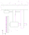
FIG. 1 is a schematic structural view of a radial flow type sedimentation tank in example 1 of the present invention;
FIG. 2 is an enlarged view of a portion A of FIG. 1;
FIG. 3 is a schematic view showing the construction of a washing brush in example 1 of the present invention;
fig. 4 is a schematic structural view of a water outlet weir plate in embodiment 1 of the utility model;
fig. 5 is a schematic structural view of a water outlet weir plate in embodiment 2 of the utility model;
FIG. 6 is a schematic diagram of the relative positions of the automatic cleaning system for the weir plate, the working bridge and the weir in embodiment 3 of the present invention;
FIG. 7 is a schematic structural view of an automatic cleaning system for an effluent weir plate according to embodiment 5 of the present invention;
FIG. 8 is a schematic structural view of an automatic cleaning system for an effluent weir plate according to embodiment 6 of the present invention;
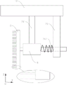
FIG. 9 is a schematic structural view of an automatic cleaning system for an effluent weir plate according to embodiment 7 of the present invention;
FIG. 10 is a schematic structural view of an automatic cleaning system for an effluent weir plate according to embodiment 8 of the present invention;
FIG. 11 is a schematic structural view of an automatic cleaning system for an effluent weir plate according to embodiment 9 of the present invention;
fig. 12 is a schematic structural diagram of a radial flow sedimentation tank in the prior art.
Detailed Description
The utility model is further illustrated by the following examples and figures.
In the following embodiments, an automatic cleaning system for the effluent weir plate installed on a working bridge is mainly added on a radial sedimentation tank, so that the manual workload in the cleaning process is reduced, the operation safety is improved, and the problems of size deviation and position deviation of the effluent weir plate caused by construction and equipment installation can be better adapted; the structures of the working bridge, the mud scraper, the water inlet system, the water outlet system and the like on the radial flow sedimentation tank are designed according to the existing products, and are not limited to the structures of the following embodiments.
Example 1
In this embodiment, the sewage treatment system includes a radial flow type sedimentation tank 1 as shown in fig. 1 to 3 and a pipeline system for delivering sewage to be treated to the radial flow type sedimentation tank 1, and during operation, the radial flow type sedimentation tank 1 is used for carrying out sedimentation treatment on the sewage to be treated injected by the pipeline system.
The radial flow sedimentation tank 1 comprises a tank body 10, a water inlet central pipe 2 arranged at the center of the tank body 10, a ring-shaped water outlet weir 3 arranged at the periphery of the tank body 10, a mud scraper 11 and a radial working bridge 12 which can rotate around the water inlet central pipe 2, a rotary driving device for driving the mud scraper 11 and the working bridge 12 to synchronously rotate around the water inlet central pipe 2, a water outlet weir plate 4 at least arranged on one side of the water outlet weir 3, and a water outlet weir plate automatic cleaning system 5 arranged on the working bridge 12; the automatic cleaning system 5 is located above the bottom surface 30 of the weir 3, and is at least used for cleaning the side surface of the weir 4 facing the weir trough, in this embodiment, only used for cleaning the plate surface of the weir 4 facing the weir trough.
As for the structure of the tank body 10, the shape is generally a cylindrical structure, the water inlet is arranged at the center of the tank, the water outlet is arranged at the periphery of the tank, specifically, a central pipe 2 which is arranged along the vertical extension is arranged at the center of the tank, perforated baffles 21 are arranged around the central pipe 2 to form an inflow area, sewage enters the central pipe 2 from a water inlet pipe 22 arranged at the bottom of the tank, and the perforated baffles 21 are utilized to enable the sewage to uniformly distribute and flow in the tank body 10 along the radial direction; the outflow region is arranged at the periphery of the tank, and is the annular effluent weir 3 which is arranged approximately in a circle with the tank body 10 and is used for collecting effluent and leading the water flow after sedimentation treatment out of the tank body 10 through an effluent pipe 31; in order to intercept floating materials floating on the water surface, a baffle plate and a scum discharge device are arranged in front of the effluent weir 3, and the design can be specifically designed according to the existing products.
The bottom of the pool body 10 is provided with a sludge collecting hopper 14, and the collected precipitated sludge is discharged out of the pool through a sludge discharge pipe 13; in order to better discharge the mud, the mud scraper 11 and the working bridge 12 which rotate around the central pipe 2 are arranged in the pond; the arrangement of the working bridge 12 is convenient for equipment maintenance, cleaning and walking when observing the pool surface, and can provide support strength for the mud scraper 11.
In the present embodiment, the weir plate 4 installed on the inner wall of the weir 3 adopts a single-side zigzag weir structure as shown in fig. 4; during the sewage treatment process, floating mud, sediments or attachments such as moss, weeds and the like are gathered on the zigzag overflow weir, so that the sewage is not discharged favorably, the landscape is influenced, and the effluent quality can be influenced seriously; the above-mentioned automatic cleaning system for the effluent weir plate is installed on the working bridge 12, so as to be able to clean at least the attachments gathered on the panel 40 to be cleaned of the effluent weir plate 4 during the rotation process around the central tube 2 along with the working bridge 12, i.e. the surface of the effluent weir plate 4 facing the effluent weir trough constitutes the panel 40 to be cleaned in this embodiment.
As shown in fig. 1 to 3, the automatic outlet weir plate washing system 5 comprises a washing brush 6, a pinch regulation device 7 and a rotary drive 8 for driving the rotation of the washing brush 6. The compacting adjustment device 7 is used for adjusting the distance between the elastic hard bristles of the cleaning brush 6 and the surface to be cleaned of the weir plate 4, so that the bristles of the cleaning brush 6 are forced to be tightly pressed on the surface to be cleaned of the weir plate 4 in the cleaning process. Specifically, in the present embodiment, the rotary driver 8 is a waterproof rotary motor; the compressing and adjusting device 7 is a displacement output device, and specifically can adopt a linear displacement output device formed by a rotary driving motor and a rack and pinion mechanism or a four-bar nut mechanism, and is at least used for driving the cleaning brush 6 to move along the extension of the working bridge 12 relative to the working bridge 12 so as to drive the cleaning brush 6 to adjust the distance between the cleaning brush 6 and the board surface 40 to be cleaned of the effluent weir plate 4, so that the cleaning brush 6 can be compressed on the board surface 40 to be cleaned in the cleaning process.
As shown in fig. 2, the washing brush 6 is constructed and installed to be mounted on the rotor of the rotary drive 8, and the washing brush 6 includes a rotation connecting shaft 60 arranged in a vertical direction and vertical plate surface washing bristles 61 fixed to the circumferential surface of the rotation connecting shaft 60. Specifically, as shown in fig. 3, the riser surface cleaning bristles 61 include weir surface cleaning bristles 610 having a relatively long radius and trough surface cleaning bristles 611 having a relatively short radius, so that the trough surface 31 of the effluent weir 3 can be cleaned during the cleaning of the panel 40 to be cleaned.
In the working process, the distance between the rotating axis of the rotating driver 8 and the plate surface to be cleaned of the water outlet weir plate 4 at the initial position is measured by rotating the distance measuring device along with the working bridge 12 for a circle around the central tube 2, so that in the cleaning process, the pressing and adjusting device 7 adjusts the distance between the outer peripheral surface of the rotating connecting shaft 60 and the plate surface to be cleaned at present to be less than the length of the cleaning bristles 61 of the vertical plate surface according to the distance and the initial position obtained by measurement at different corner positions around the central tube 2, so that the cleaning bristles 61 of the vertical plate surface are kept to be in a bent state and elastically pressed on the plate surface to be cleaned at present constantly, and the distance is greater than a preset safe distance to avoid the rotating connecting shaft 60 from touching the plate surface to be cleaned, so as to avoid damaging equipment; thereby through setting up the play weir board self-cleaning system 5 of installing on service bridge 12, not only can utilize service bridge 12 to rotate the rotary motion of in-process around the central siphon 2 of intaking, in order to drive the cleaning brush and rotate around the central siphon 2 of intaking, and wash annular play weir 3 and the inboard face of play weir board 4 at least, utilize sticis adjusting device 7 to adjust the interval between the face 40 that treats of cleaning brush and play weir board 4 simultaneously, thereby can satisfy the radial displacement deviation that exists between the face 40 that treats cleaning that factors such as design, construction arouse and the design periphery, thereby wash different positions well.
Example 2
As an explanation of embodiment 2 of the present invention, only differences from embodiment 1 will be explained below.
In this embodiment, the weir plate installed on the wall of the weir adopts a double-sided zigzag weir structure as shown in fig. 5, that is, it includes an inner weir plate 401 and an outer weir plate 402. At this time, the compacting adjustment device 7 is required to at least drive the cleaning brush 6 to move relative to the working bridge 12 along the extension of the working bridge 12 by a distance greater than the distance between the inner plate surfaces of the outer and inner weir plates, so as to drive the cleaning brush 6 to adjust the distance between the cleaning brush 6 and the plate surface to be cleaned 403 of the outer weir plate 401, and adjust the distance between the cleaning brush 6 and the plate surface to be cleaned 404 of the outer weir plate 402, so as to enable the cleaning brush 6 to be compacted on the plate surface to be cleaned 403 or the plate surface to be cleaned 404 during the cleaning process.
In the working process, based on the change of the distance between the rotor axis of the rotary driver at the initial position of the plate surface 403 to be cleaned or the plate surface 404 to be cleaned, the compressing force between the bristles and the plate surface to be cleaned is adjusted by the compressing and adjusting device 7, so that the cleaning effect is ensured, meanwhile, the influence of deviation caused by construction is effectively reduced, and the equipment is prevented from being damaged.
Example 3
As an explanation of embodiment 3 of the present invention, only differences from embodiment 2 will be explained below.
As shown in fig. 6, in the present embodiment, in order to clean the outer side surfaces of the inner water outlet weir plate 401 and the outer water outlet weir plate 402, that is, the plate surface of the inner tank facing away from the water outlet weir 3, the pushing and pressing adjusting device 7 may be configured as a two-dimensional displacement output device, and the rotary actuator 8 may be attached to the actuator tip of the two-dimensional displacement output device, so that the cleaning brush 6 may be independently driven and moved in the height direction and the extending direction of the operation bridge 12, and the position of the cleaning brush 6 may be adjusted to be located outside the water outlet weir 3, and the plate surfaces of the inner tank attached to the inner water outlet weir plate 401 and the outer water outlet weir plate 402 facing away from the water outlet weir 3 may be cleaned.
The two-dimensional displacement output device can be constructed by a manipulator or two linear displacement output devices. As shown in fig. 6 and with reference to the structure shown in fig. 1, specifically, the two-dimensional displacement output device includes a traverse slide 70 mounted on the working bridge 12 movably in the extending direction of the working bridge 12, a traverse actuator for driving the traverse slide 70 to move in the extending direction, and a lift actuator 71 mounted on the traverse slide 70; and the stator of the rotary driver 8 is mounted on the lift mover of the lift driver 71. The two-dimensional displacement output device can drive the movement displacement of the washing brush 6 in the extending direction of the working bridge 12 to be larger than the widths of the two outer sides of the inner water outlet weir plate 403 and the outer water outlet weir plate 404, and can raise the washing brush 6 to be positioned above the two water outlet weir plates in the height direction.
During operation, the position of the washing brush 6 can be adjusted to the outer side of the water outlet weir plate by lifting, so that the attachments accumulated on the outer plate surface of the water outlet weir plate can be washed.
Example 4
As an explanation of embodiment 4 of the present invention, only differences from embodiment 1 will be explained below.
In this embodiment, referring to the configuration shown in fig. 3, the washing brush 6 includes the groove bottom surface washing bristles fixed to the lower end portion of the rotation connecting shaft 60, and can wash the attached matter on the groove bottom surface 30 of the weir 3 shown in fig. 2.
Example 5
As a description of embodiment 5 of the present invention, only the differences from embodiment 1 described above will be described below, specifically, the structure of the brush and the connection structure thereof will be improved.
As shown in fig. 7, the cleaning brush 6 is a disk-shaped brush structure arranged vertically, the rotation axis of the rotary driver 8 is arranged horizontally, the compressing and adjusting device 7 comprises a mounting support 75 for mounting the rotary driver 8, a traverse slide block 76 for driving the rotary driver 8 to move along the extending direction of the working bridge 12, a rotary motor 77 and a screw-nut mechanism 78, the traverse slide block 76 is fixedly connected with the screw nut of the screw-nut mechanism 78, the screw of the screw-nut mechanism 78 is fixedly connected with the rotor of the rotary motor 77, and the traverse slide block 76 is movably mounted on the working bridge 12 along the extending direction of the working bridge 12; therefore, in the working process, the rotary motor 77 is utilized to drive the lead screw on the lead screw nut mechanism 78 to rotate, so as to drive the traverse slide block 76 to reciprocate along the extending direction of the working bridge 12, and thus, the compressing state between the cleaning brush 6 and the board surface to be cleaned is adjusted.
Example 6
As a description of embodiment 6 of the present invention, only the differences from embodiment 5 described above will be described below.
Referring to fig. 8, the automatic washing system of the effluent weir plate further comprises a surface detection device 90, configured to perform predictive detection on the relative position between the face to be washed and the washing brush 6 on the surface to be washed on the effluent weir plate 4; the surface detecting device 90 is located on the upstream side of the washing brush 6 in the rotation direction of the working bridge 12 around the water inlet center tube 2. Therefore, in the working process, the cleaning can be carried out while detection is carried out according to the actual condition so as to prevent the structural deformation of the pool after construction and avoid the need of carrying out distance measurement in advance.
Example 7
As an explanation of embodiment 7 of the present invention, only the differences from embodiment 5 described above will be explained below.
Referring to fig. 9, the compression adjusting device 7 includes an elastic return mechanism instead of the displacement output device in the previous embodiment, thereby reducing the use of power device; namely, the pressing adjustment device 7 comprises a mounting support 75 for mounting the rotary driver 8, a mounting slide 791 for driving the rotary driver 8 to move along the extending direction of the working bridge 12, and a compression spring 792; the mounting slider 791 is mounted on the working bridge 12 so as to be movable in the extending direction of the working bridge 12, and the washing brush 6 and the rotary driver 8 are both mounted on the mounting slider 791; in operation, the compression spring 792 constitutes an elastic return mechanism in this embodiment, and its elastic restoring force is used to force the mounting slide 791 to move towards the direction close to the board to be cleaned on the weir plate 4 relative to the working bridge 12, so as to drive the cleaning brush to elastically press against the board to be cleaned.
Example 8
As an explanation of example 8 of the present invention, only differences from example 5 described above will be explained below.
Referring to fig. 10, the automatic washing system of the effluent weir plate further comprises an effluent nozzle 793 for spraying a washing water stream to the washing brush 6 in operation; the outlet nozzle 793 is located on the downstream side of the washing brush 6 in the rotating direction of the working bridge 12 around the inlet center pipe 2. For the water outlet spray head 793, a water suction pump can be directly adopted to suck water from the sedimentation tank 1 for flushing.
The technical scheme of improving the cleaning effect by additionally arranging the water outlet nozzle is also applicable to the technical scheme of the embodiment 1 and the like, and is not described herein again. The cleaning target of the water jet may be the current brush plate surface described above, may be a cleaning brush, or may be the current brush plate surface cleaned together with the cleaning brush. The relative position between the water outlet 793 and the brush 6 is set according to the actual situation, and is not limited to the above-described configuration in the present embodiment.
Example 9
As a description of embodiment 9 of the present invention, only the differences from embodiment 7 described above will be described below.
Referring to fig. 11, in this embodiment, it is necessary to clean the inner and outer weir plates shown in fig. 5 by using the washing brush 6, at this time, the position of the washing brush 6 is elastically pressed from both sides by using the compression spring 795 and the compression spring 796, and the mounting slide 797 is driven by the linear displacement output device to move along the extension of the working bridge 12 in the opposite direction during the operation, so as to clean the plate surface to be cleaned of one of the weir plates. Specifically, two connecting rods 7971 and 7972 which are vertically arranged and a transverse loop bar 7973 fixed on the two connecting rods are arranged on the mounting sliding seat 797; the stator of the rotary driver 8 is sleeved on the transverse loop bar 7973 only in a transverse sliding way; compression spring 795 and compression spring 796 all suit are on horizontal loop bar 7973, and are located the stator both sides of rotary actuator 8 to can be from both sides treat the washing face elasticity sticis.
In this embodiment, the vertical displacement driving mechanism may be provided in the vertical direction, so that the position of the cleaning brush 6 in the vertical direction can be adjusted to clean the outer side surface of the weir plate by changing the position.
In the above embodiments, the radial sedimentation tank with a central water inlet pipe for central water inlet is taken as an example to explain the utility model point of the application; the main invention of the present application is to add a cleaning device, which is also suitable for improving a radial sedimentation tank for peripheral water inflow and peripheral water drainage, so as to achieve the corresponding technical effect, and the improvement of the peripheral water inflow sedimentation tank is not described herein again.
Claims (10)
1. An automatic cleaning system for an effluent weir plate is used for cleaning a radial flow sedimentation tank; the radial flow sedimentation tank comprises a tank body, a ring groove-shaped water outlet weir arranged at the periphery of the tank body, a mud scraper and a radial working bridge which can rotate around the central shaft of the tank body, a rotary driving device for driving the mud scraper and the working bridge to rotate around the central shaft, and at least one water outlet weir plate arranged on one side of the water outlet weir; the method is characterized in that:
the automatic cleaning system of the water outlet weir plate is arranged on the working bridge and is positioned on the upper side of the bottom surface of the water outlet weir; the automatic cleaning system of the water outlet weir plate comprises a cleaning brush, a compressing and adjusting device and a rotary driver for driving the cleaning brush to rotate;
the pressing and adjusting device is used for adjusting the distance between the cleaning brush and the surface to be cleaned of the water outlet weir plate so as to force the cleaning brush to be pressed tightly on the surface to be cleaned in the cleaning process.
2. The automatic washing system for an effluent weir plate of claim 1, wherein:
the adjusting device that sticiss includes displacement output device, is used for ordering about at least the cleaning brush is relative the transaxle removes, in order to drive the cleaning brush and adjust the cleaning brush with treat the interval between the cleaning plate face, in order to enable the cleaning brush in the cleaning process sticis in treat on the cleaning plate face.
3. The automatic washing system for an effluent weir plate of claim 2, wherein:
the displacement output device is a two-dimensional displacement output device, and can independently drive the cleaning brush to move in the height direction and the extending direction of the working bridge.
4. The automatic washing system for an effluent weir plate of claim 3, wherein:
the cleaning brush is arranged on a rotor of the rotary driver;
the two-dimensional displacement output device comprises a traverse slide seat which is movably arranged on the working bridge along the extension direction, a traverse driver for driving the traverse slide seat to move along the extension direction, and a lifting driver arranged on the traverse slide seat; the stator of the rotary driver is arranged on the lifting rotor of the lifting driver;
two-dimensional displacement output device can order about the cleaning brush is in the ascending removal displacement of extending direction is greater than go out the two outside widths of weir, and can make the cleaning brush risees to being located in the direction of height go out the top side of weir plate.
5. The automatic washing system for an effluent weir plate of claim 1, wherein:
the pressing adjusting device comprises an elastic resetting mechanism and a mounting sliding seat, the mounting sliding seat is movably mounted on the working bridge along the extending direction of the working bridge, and the cleaning brush and the rotary driver are both mounted on the mounting sliding seat;
elastic restoring force of the elastic resetting mechanism is used for forcing the installation sliding seat to be relative to the working bridge to move towards the direction close to the board surface to be cleaned, so that the cleaning brush is driven to be elastically and tightly pressed on the board surface to be cleaned.
6. An automatic cleaning system for an effluent weir plate according to any one of claims 1 to 5, wherein:
the water outlet weir plate is of a sawtooth-shaped overflow weir structure.
7. An automatic cleaning system for an effluent weir plate according to any one of claims 1 to 5, wherein:
the cleaning brush includes along vertical arrangement's rotary connection axle and sets firmly vertical face cleaning brush hair on rotary connection axle global.
8. The automated weir plate cleaning system of claim 7, wherein:
the cleaning brush includes that the setting is in the tank bottom surface cleaning brush hair on the lower tip of rotatory connecting axle.
9. An automatic cleaning system for an effluent weir plate according to any one of claims 1 to 5, wherein:
the automatic water outlet weir plate cleaning system also comprises a surface detection device, which is used for performing predictive detection on the relative position between the surface to be cleaned and the cleaning brush on the surface of the plate to be cleaned; the surface detecting device is located on an upstream side of the cleaning brush in a rotation direction of the working bridge around the central shaft;
the automatic cleaning system for the water outlet weir plate further comprises a water outlet spray head, and the water outlet spray head is used for spraying cleaning water flow to the current brushing plate surface on the water outlet weir plate and/or the cleaning brush.
10. A sewage treatment system comprises a radial flow sedimentation tank and a pipeline system used for conveying sewage to be treated to the radial flow sedimentation tank, and is characterized in that:
an automatic effluent weir plate cleaning system is arranged on the radial flow sedimentation tank, and is the automatic effluent weir plate cleaning system in any one of claims 1 to 9.
Priority Applications (1)
| Application Number | Priority Date | Filing Date | Title |
|---|---|---|---|
| CN202120806074.XU CN215781712U (en) | 2021-04-20 | 2021-04-20 | Sewage treatment system and automatic cleaning system for effluent weir plate thereof |
Applications Claiming Priority (1)
| Application Number | Priority Date | Filing Date | Title |
|---|---|---|---|
| CN202120806074.XU CN215781712U (en) | 2021-04-20 | 2021-04-20 | Sewage treatment system and automatic cleaning system for effluent weir plate thereof |
Publications (1)
| Publication Number | Publication Date |
|---|---|
| CN215781712U true CN215781712U (en) | 2022-02-11 |
Family
ID=80171452
Family Applications (1)
| Application Number | Title | Priority Date | Filing Date |
|---|---|---|---|
| CN202120806074.XU Active CN215781712U (en) | 2021-04-20 | 2021-04-20 | Sewage treatment system and automatic cleaning system for effluent weir plate thereof |
Country Status (1)
| Country | Link |
|---|---|
| CN (1) | CN215781712U (en) |
-
2021
- 2021-04-20 CN CN202120806074.XU patent/CN215781712U/en active Active
Similar Documents
| Publication | Publication Date | Title |
|---|---|---|
| CN105457349B (en) | A kind of anti-disturbance lifting center drive mud-scraper | |
| CN2910324Y (en) | Micro solid/liquid separator | |
| CN102284199B (en) | Automatic water treatment backwashing device | |
| CN208525911U (en) | Center driving scraping and sucking machine | |
| CN112245979B (en) | High-efficient sedimentation tank convenient to clearance | |
| KR100961735B1 (en) | A Circular type settling pond with sludge discharging apparatus | |
| CN106693480A (en) | Brush type self-washing filter | |
| CN217204599U (en) | Effluent water sump self-cleaning drainage device | |
| CN215995731U (en) | Sludge discharging device and sewage treatment system for water treatment plant | |
| CN217027245U (en) | Device for removing bottom mud of sewage tank | |
| CN210021359U (en) | A effluent treatment plant for resin production | |
| CN215781712U (en) | Sewage treatment system and automatic cleaning system for effluent weir plate thereof | |
| CN114377463A (en) | High efficiency sewage residue processing apparatus | |
| CN207307284U (en) | A kind of rectangular sedimentation tank equipped with chain-belt type mud scraper for sewage treatment plant | |
| CN210523312U (en) | Sewage treatment plant inclined plate sedimentation tank goes out basin cleaning equipment | |
| CN102921210B (en) | Unpowered automatic back-flushing screening device for culture water treatment | |
| CN211097696U (en) | Slag scraping machine for sewage treatment | |
| CN104208941A (en) | Fiber rotary disk filtration tank | |
| CN209076152U (en) | A kind of grid slag water-removing press | |
| CN110917668A (en) | Precipitation device for sewage treatment | |
| CN108375118B (en) | Factory dust control equipment beneficial to environmental protection | |
| CN212982506U (en) | Sediment cleaning device for sewage treatment | |
| CN214597583U (en) | Waste water residue filtering device | |
| CN211278611U (en) | Rubber sheet processing device | |
| CN202876475U (en) | Unpowered automatic backflush screening device for aquaculture water treatment |
Legal Events
| Date | Code | Title | Description |
|---|---|---|---|
| GR01 | Patent grant | ||
| GR01 | Patent grant |