EP3790469B1 - Ultrasound system with automated wall tracing - Google Patents
Ultrasound system with automated wall tracing Download PDFInfo
- Publication number
- EP3790469B1 EP3790469B1 EP19800213.1A EP19800213A EP3790469B1 EP 3790469 B1 EP3790469 B1 EP 3790469B1 EP 19800213 A EP19800213 A EP 19800213A EP 3790469 B1 EP3790469 B1 EP 3790469B1
- Authority
- EP
- European Patent Office
- Prior art keywords
- ultrasound
- image data
- imaging modality
- physiological parameters
- processor
- Prior art date
- Legal status (The legal status is an assumption and is not a legal conclusion. Google has not performed a legal analysis and makes no representation as to the accuracy of the status listed.)
- Active
Links
Images


Classifications
-
- A—HUMAN NECESSITIES
- A61—MEDICAL OR VETERINARY SCIENCE; HYGIENE
- A61B—DIAGNOSIS; SURGERY; IDENTIFICATION
- A61B8/00—Diagnosis using ultrasonic, sonic or infrasonic waves
- A61B8/48—Diagnostic techniques
- A61B8/486—Diagnostic techniques involving arbitrary m-mode
-
- A—HUMAN NECESSITIES
- A61—MEDICAL OR VETERINARY SCIENCE; HYGIENE
- A61B—DIAGNOSIS; SURGERY; IDENTIFICATION
- A61B8/00—Diagnosis using ultrasonic, sonic or infrasonic waves
- A61B8/06—Measuring blood flow
- A61B8/065—Measuring blood flow to determine blood output from the heart
-
- A—HUMAN NECESSITIES
- A61—MEDICAL OR VETERINARY SCIENCE; HYGIENE
- A61B—DIAGNOSIS; SURGERY; IDENTIFICATION
- A61B8/00—Diagnosis using ultrasonic, sonic or infrasonic waves
- A61B8/08—Clinical applications
- A61B8/0883—Clinical applications for diagnosis of the heart
-
- A—HUMAN NECESSITIES
- A61—MEDICAL OR VETERINARY SCIENCE; HYGIENE
- A61B—DIAGNOSIS; SURGERY; IDENTIFICATION
- A61B8/00—Diagnosis using ultrasonic, sonic or infrasonic waves
- A61B8/08—Clinical applications
- A61B8/0891—Clinical applications for diagnosis of blood vessels
-
- A—HUMAN NECESSITIES
- A61—MEDICAL OR VETERINARY SCIENCE; HYGIENE
- A61B—DIAGNOSIS; SURGERY; IDENTIFICATION
- A61B8/00—Diagnosis using ultrasonic, sonic or infrasonic waves
- A61B8/13—Tomography
- A61B8/14—Echo-tomography
-
- A—HUMAN NECESSITIES
- A61—MEDICAL OR VETERINARY SCIENCE; HYGIENE
- A61B—DIAGNOSIS; SURGERY; IDENTIFICATION
- A61B8/00—Diagnosis using ultrasonic, sonic or infrasonic waves
- A61B8/46—Ultrasonic, sonic or infrasonic diagnostic devices with special arrangements for interfacing with the operator or the patient
- A61B8/461—Displaying means of special interest
- A61B8/463—Displaying means of special interest characterised by displaying multiple images or images and diagnostic data on one display
-
- A—HUMAN NECESSITIES
- A61—MEDICAL OR VETERINARY SCIENCE; HYGIENE
- A61B—DIAGNOSIS; SURGERY; IDENTIFICATION
- A61B8/00—Diagnosis using ultrasonic, sonic or infrasonic waves
- A61B8/52—Devices using data or image processing specially adapted for diagnosis using ultrasonic, sonic or infrasonic waves
- A61B8/5215—Devices using data or image processing specially adapted for diagnosis using ultrasonic, sonic or infrasonic waves involving processing of medical diagnostic data
- A61B8/5223—Devices using data or image processing specially adapted for diagnosis using ultrasonic, sonic or infrasonic waves involving processing of medical diagnostic data for extracting a diagnostic or physiological parameter from medical diagnostic data
-
- A—HUMAN NECESSITIES
- A61—MEDICAL OR VETERINARY SCIENCE; HYGIENE
- A61B—DIAGNOSIS; SURGERY; IDENTIFICATION
- A61B8/00—Diagnosis using ultrasonic, sonic or infrasonic waves
- A61B8/52—Devices using data or image processing specially adapted for diagnosis using ultrasonic, sonic or infrasonic waves
- A61B8/5215—Devices using data or image processing specially adapted for diagnosis using ultrasonic, sonic or infrasonic waves involving processing of medical diagnostic data
- A61B8/5238—Devices using data or image processing specially adapted for diagnosis using ultrasonic, sonic or infrasonic waves involving processing of medical diagnostic data for combining image data of patient, e.g. merging several images from different acquisition modes into one image
- A61B8/5261—Devices using data or image processing specially adapted for diagnosis using ultrasonic, sonic or infrasonic waves involving processing of medical diagnostic data for combining image data of patient, e.g. merging several images from different acquisition modes into one image combining images from different diagnostic modalities, e.g. ultrasound and X-ray
-
- A—HUMAN NECESSITIES
- A61—MEDICAL OR VETERINARY SCIENCE; HYGIENE
- A61B—DIAGNOSIS; SURGERY; IDENTIFICATION
- A61B8/00—Diagnosis using ultrasonic, sonic or infrasonic waves
- A61B8/52—Devices using data or image processing specially adapted for diagnosis using ultrasonic, sonic or infrasonic waves
- A61B8/5269—Devices using data or image processing specially adapted for diagnosis using ultrasonic, sonic or infrasonic waves involving detection or reduction of artifacts
- A61B8/5276—Devices using data or image processing specially adapted for diagnosis using ultrasonic, sonic or infrasonic waves involving detection or reduction of artifacts due to motion
-
- A—HUMAN NECESSITIES
- A61—MEDICAL OR VETERINARY SCIENCE; HYGIENE
- A61B—DIAGNOSIS; SURGERY; IDENTIFICATION
- A61B8/00—Diagnosis using ultrasonic, sonic or infrasonic waves
- A61B8/52—Devices using data or image processing specially adapted for diagnosis using ultrasonic, sonic or infrasonic waves
- A61B8/5284—Devices using data or image processing specially adapted for diagnosis using ultrasonic, sonic or infrasonic waves involving retrospective matching to a physiological signal
-
- A—HUMAN NECESSITIES
- A61—MEDICAL OR VETERINARY SCIENCE; HYGIENE
- A61B—DIAGNOSIS; SURGERY; IDENTIFICATION
- A61B8/00—Diagnosis using ultrasonic, sonic or infrasonic waves
- A61B8/52—Devices using data or image processing specially adapted for diagnosis using ultrasonic, sonic or infrasonic waves
- A61B8/5292—Devices using data or image processing specially adapted for diagnosis using ultrasonic, sonic or infrasonic waves using additional data, e.g. patient information, image labeling, acquisition parameters
-
- G—PHYSICS
- G16—INFORMATION AND COMMUNICATION TECHNOLOGY [ICT] SPECIALLY ADAPTED FOR SPECIFIC APPLICATION FIELDS
- G16H—HEALTHCARE INFORMATICS, i.e. INFORMATION AND COMMUNICATION TECHNOLOGY [ICT] SPECIALLY ADAPTED FOR THE HANDLING OR PROCESSING OF MEDICAL OR HEALTHCARE DATA
- G16H50/00—ICT specially adapted for medical diagnosis, medical simulation or medical data mining; ICT specially adapted for detecting, monitoring or modelling epidemics or pandemics
- G16H50/30—ICT specially adapted for medical diagnosis, medical simulation or medical data mining; ICT specially adapted for detecting, monitoring or modelling epidemics or pandemics for calculating health indices; for individual health risk assessment
-
- A—HUMAN NECESSITIES
- A61—MEDICAL OR VETERINARY SCIENCE; HYGIENE
- A61B—DIAGNOSIS; SURGERY; IDENTIFICATION
- A61B8/00—Diagnosis using ultrasonic, sonic or infrasonic waves
- A61B8/06—Measuring blood flow
Definitions
- the present invention relates to an ultrasound imaging system and to a method of operating a processor in an ultrasound imaging system.
- Ultrasound systems that provide real time physiological measurements from ultrasound image data are disclosed.
- ultrasound is becoming an increasingly used imaging modality for human and animal subjects.
- ultrasound can also be used to provide quantitative assessments of physiological functions that can be used by researchers or medical care providers.
- quantitative assessments are those related to cardiac function.
- Physiological parameters such as ejection fraction (EF), fractional shortening (FS), stoke volume (SV) and cardiac output (CO) are well known measurements used in diagnosing and staging patients.
- EF ejection fraction
- FS fractional shortening
- SV stoke volume
- CO cardiac output
- a physician, ultrasound technician or other skilled health care provider that wants an indication of cardiac output first performs an ultrasound examination. After the ultrasound image data are captured and stored, the operator reviews the image data and manually places markers on the images over certain tissue features or sends the images to a radiologist to place the markers. The distance between these markers is then used to compute the physiological parameters. Having the ability to display such physiological parameters in real time while a subject is being examined will enable a medical provider to make diagnostic decisions more rapidly without stopping to make measurements manually or having to send images to a radiology department.
- the disclosed technology relates to an ultrasound imaging system that computes real time physiological parameters from measurement of features in ultrasound image data using a neural network.
- the invention provides an ultrasound imaging system according to claim 1.
- the processor may determine measurements of the physical features.
- Cardiac functional parameters can be calculated using M-Mode images acquired from the parasternal long axis view.
- a typical method involves making measurements of the thickness of the interventricular septum (IVS) or the right ventricle wall (RVID), the left ventricular interior diameter (LVID), the left ventricle posterior wall (LVPW) at both systole (;s) and diastole (;d), and the heart rate.
- IVS interventricular septum
- RVD right ventricle wall
- LVID left ventricular interior diameter
- LVPW left ventricle posterior wall
- LVID measurements at both systole and diastole are needed to calculate measures of cardiac function.
- These measurements can be made manually on a static (during review; not live) image, and can include measurements of the heart rate (either directly from the image or by using the ECG signal if available).
- LVID;d and LVID;s are measured at the minimum and maximum separation points between these two traces.
- the heart rate can be extracted using the time difference from multiple systole-to-systole periods or from the ECG trace if available.
- the processor in the ultrasound system computes cardiac output parameters in real time as ultrasound images are captured.
- the processor provides M-Mode ultrasound images to a neural network that is trained to identify the endocardial border from the images. From the identified location of the walls of the endocardium, the processor can compute cardiac parameters that are displayed in real time along with ultrasound image data. This process can be applied to clinical (human) imaging situations as well as preclinical (animal models such as mouse and rat) imaging.
- Automatic endocardial wall tracing relieves the operator from the laborious work of manual tracing and also provides multiple systolic and diastolic points that can be measured to provide cycle averaging. It also facilitates the option of real time measurements, which would be impossible otherwise.
- the invention provides a method of operating a processor in an ultrasound imaging system according to claim 11.
- the conventional method of computing physiological parameters from ultrasound image data is to manually place one or more markers on an ultrasound image and compute the parameters from the measurements associated with the placement of the markers.
- Figure 1 shows an example of an M-Mode ultrasound image 10 of a mouse cardiac left ventricle that is beating over a number of cardiac cycles.
- the image includes a number of markers (e.g. plus "+" signs) that are manually placed by a user over the contour of physical features that can be seen in the image data.
- the markers are located on a pair of opposing endocardial walls that compress toward each other during the systole phase of the cardiac cycle and expand away from each other during diastole phase of the cardiac cycle.
- a processor in the ultrasound system computes a pair of curves that join the manually placed markers using a curve fitting technique such as splines or the like.
- the distance between the upper curve and the lower curve at the systolic and diastolic points in the cardiac cycle allows various cardiac parameters to be computed.
- the ultrasound image 10 also includes EKG and respiratory information obtained from other sensors connected to the ultrasound machine.
- the disclosed technology relates to an ultrasound system that uses software or programmable logic to automatically identify physical features in an image. This allows physiological parameters to be computed and shown to the operator in real time.
- FIG. 2 shows a representative ultrasound system with which the disclosed technology can be implemented.
- An ultrasound imaging system 50 can comprise a hand held, portable or cart-based imaging system.
- the ultrasound system 50 connects with one or more ultrasound transducers 54 that transmit ultrasound signals into a subject (not shown) and receive the corresponding echo signals from the subject.
- the ultrasound system 50 can receive signals from respiration sensors.
- the ultrasound system 50 can receive signals from one or more additional external sensors 56 such as SPO2 sensors, EKG sensors or the like.
- the ultrasound imaging system 50 includes one or more displays on which ultrasound data are displayed.
- the displays may include a touch sensitive display such that the operator can operate the system using touch commands.
- the ultrasound imaging system 50 also includes communication circuitry to connect to one or more remotely located systems through a wired or wireless computer communication link.
- the ultrasound imaging system 50 includes image processing circuitry having one or more processors (e.g. CPUs, DSPs, GPUs, AS ICs, FPGAs or a combination thereof) that are configured to execute programmed instructions stored in a processor readable memory or that perform pre-determined logical operations to implement a neural network that is trained to analyze ultrasound image data in order to mark the location of physical features in the image.
- the physical features are a pair of opposing ventricle walls (anterior left ventricular wall/interventricular septum and the posterior left ventricular wall) that define the volume of the left ventricle.
- the ultrasound image is an M-Mode ultrasound image obtained in a parasternal long axis view (PLAX).
- the disclosed example is described with respect to identifying the location of the opposing ventricular walls, it will be appreciated that the disclosed technology is extendable to identifying other tissue structures in ultrasound image data including vessel walls, heart valves, esophageal tissue in the case of transesophageal imaging or stomach or intestine tissue in the case of gastric imaging.
- the processor in the ultrasound imaging system is configured to provide ultrasound image data to a neural network 70 that is trained to identify the location of the desired physical features.
- the neural network 70 is trained to identify the upper and lower boundaries of the endocardial walls and the interior of the cardiac ventricle in a column of ultrasound image pixel data.
- the boundary is generally characterized by a relatively bright reflection that is adjacent a black region representing a volume filled with non-reflecting blood.
- high frequency imaging e.g. 20+ MHz
- ultrasound is reflected from the blood cells in the ventricle making the boundary area more difficult to visually detect.
- test images 80 are provided to a neural network training engine 100 as shown in Figure 3 .
- the test images 80 are images of ultrasound data with the features to be identified (e.g. the vessel walls) previously expertly marked.
- the images are a uniform size such as 256 pixels wide by 128 pixels high with each pixel having an eight-bit black and white brightness value. Other image sizes can also be used such as 256 pixels wide by 256 pixels high or 512 pixels wide by 64 pixels high.
- each column of data is an acquired line of ultrasound data. Data is acquired at the pulse repetition frequency (PRF).
- PRF pulse repetition frequency
- the data set comprises of a time window of 256 ms. For small animal imaging, this encompasses a number of cardiac cycles. For clinical imaging either the number of data lines used must be increased or the PRF reduced to contain more than one cycle of data.
- the pixels in each column represent samples at different depths in the image. The first pixel in each column is at the shallowest depth.
- the image data are obtained from M-Mode scans at a pulse repetition frequency (PRF) of 1500 Hz.
- PRF pulse repetition frequency
- Other PRF values could also be used; for example 1000, 1250, 1750, 2000 Hz or higher.
- a large number (e.g. 1,000-14,000 or more) training images are supplied to the neural network training engine 100 to allow the engine to determine a number of filter weights and bias values so that a convolutional neural network using the weights and bias value will return the most likely pixel locations in a column of image data that represent the ventricle walls.
- the total number of training images can be increased using data augmentation whereby the initial base set of images are increased though linear and nonlinear modifications thereby producing additional training data.
- augmentation may include both linear and nonlinear scaling or brightness or contrast changes.
- the neural network 70 is configured to receive an input image of the same size with which the neural network was trained (e.g. 256x128x1) and to produce an output data set (256x2) marking the two most likely locations of the ventricle wall boundaries in each column of image pixel data.
- an input image of the same size with which the neural network was trained e.g. 256x128x1
- an output data set 256x2
- Other input image sizes such as 512x128x1 or 256x256x1 with corresponding output sizes of 512x2 or 256x2 can also be used.
- the training data images were collected and approximately 750 traces were manually labeled, meaning the anterior and posterior left ventricular chamber walls were traced. Increasing the number of labeled training data increases the likelihood of an accurate generalization of the problem during training of the neural network. These data were formatted using C++ and Python. Data augmentation was performed to increase the amount of training data available. With augmentation, approximately 20 to 1 increase in semi-unique data instances were obtained from the initial labeled data sets.
- a model framework setup using Keras, Tensorflow, and Python was used.
- a number of different machine learning models were tested.
- a number of different machine learning models can be employed.
- variants of freely available models can be used such as VGG5, VGG16 (Visual Geometry Group at Oxford), and Mobile Net (Google).
- Custom models can also be developed. Tradeoffs using different models can include prediction accuracy and size which will affect inference speed on embedded devices. These models were modified such that they conformed to the input size and output requirements of this specific problem.
- the input data sets consisted of 256 lines of M-Mode data at a measured PRF of 1500 Hz.
- PRFs can also be used such as but not limited to 1000, 1250, 1750 or 2000 Hz.
- the data were resampled to 128 depth samples. Other depths could also be used such as 64 samples, or 256 samples. The number of samples also need not be a power of 2.
- Data were 8-bit single channel.
- the data length corresponds to approximately 1-2 heart cycles depending on the heart rate. As will be appreciated, for other applications such as for human acquired data sets, the heart rate is much lower.
- the data might be scaled appropriately to fit the same 1-2 heart cycles; or a different input size data set may be used or a different PRF setting may be used. Changing either PRF or input size will change the amount of time represented in the image.
- the ultrasound image is comprised of pixel data that is in a format that is ready to be displayed on a video monitor. It will be appreciated that the disclosed technology could also be used with other types of image data such as pre-scan conversion image data or raw ultrasound data. Therefore, as used herein, the term image data is to refer to ultrasound data that is representative of an area of interest and not only to scan converted ultrasound data.
- the output data format is 2 data points (position of anterior and posterior wall boundary) for each of the 256 input lines (see Figure 4 ). (Output data size 256x2). Further experimentation could include expanding the data length to include more lines.
- Neural network models themselves are generally interchangeable, with some providing advantages over others. For example, computational complexity and output accuracy are considerations. Currently excellent results are found using a variation of Mobile Net V1 (Google) model. Shown below is an example of this model showing the different layers and modifications required to conform to the input image size (256x128). Modifications could include using a different model, changing the number of layers, or adding additional layers such as dense layers or addition convolutional layers. Modified Mobile Net V1 model.
- Output Shape Param # vsi_input layer (InputLayer) (None, 256, 128, 1) 0 conv1 (Conv2D) (None, 128, 64, 32) 288 convi_bn (BatchNorm) convi_relu (None, 128, 64, 32) 128 (Activation) conv_dw_1 (None, 128, 64, 32) 0 (DepthwiseConv2D) (None, 128, 64, 32) 288 conv_dw_1_bn (BatchNorm) (None, 128, 64, 32) 128 conv_dw_1_relu (Activation) (None, 128, 64, 32) 0 conv_pw_1 (Conv2D) (None, 128, 64, 64) 2048 conv_pw_1_bn (BatchNorm) (None, 128, 64, 64) 256 conv_pw_1_relu (Activation) (None, 128,
- the model shown above is successful because it generates accurate results and is relatively small enabling fast computation (e.g. about 300 ms. per 256 line image on a CPU).
- a Python framework using Keras and Tensorflow was used to train this model using the prepared and augmented data.
- An Adam optimizer with variable learning rate was employed over approximately 1 million training examples.
- Other optimizers can be used; for example SGD (Stochastic Gradient Descent).
- the tradeoffs using different optimizers include convergence time, and training speed.
- a combination of 2 or more different optimizers can also be used.
- AWS Amazon Web Services
- K80 Nvidia GPU the time to train the neural network 70 was approximately 12 hours.
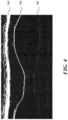
- FIG. 4 shows a representative M-Mode ultrasound image 140 containing an upper trace 142 representing an anterior wall and a lower trace 144 representing a posterior wall of a heart muscle that have been identified by the neural network 70.
- the processor analyzes the traces to determine the distance where the traces are 1) closest together and 2) farthest apart. These distances represent the heart muscle at the systolic and diastolic phases of the cardiac cycle.
- the location can be determined by analyzing the distance (in pixels) in each column of the image (e.g. by searching the image columns for the minimum and maximum pixel gap).
- the systole and diastole of the cardiac cycle can be determined from an EKG signal that is obtained simultaneously with the ultrasound data. Knowing the time difference represented between each pixel in a column, the speed of ultrasound in the tissue and the number of samples in a column between the identified locations on the traces 142, 144, the physical distance between the heart walls in the subject is calculated by the processor.
- the physiological parameters from the traces are computed by the processor.
- Ventricular volumes calculated from ventricular wall measurements can be subject to interpretation and may vary. In one example, they are approximated by the following equations. These are exemplary and may be adjusted depending on the type of subject being examined or other factors.
- the processor executes instructions to calculate and display measurements on the detected physical features such as the distance between physical features, the angle between physical features, the area of the features etc.
- the distances in millimeters between the anterior and posterior ventricular walls at systole and diastole are calculated and displayed.
- the processor can also execute instructions to calculate the distances between the outer 2 walls for additional left ventricular assessment.
- the LV Mass can be calculated when the distances between all 4 walls have been measured.
- the processor computes the distances between all 4 cardiac walls at the same time.
- the ultrasound system 50 is connected to a respiratory monitor that indicates to the ultrasound system whether the subject is breathing during the acquisition of ultrasound images.
- Image data obtained during breathing can include motion artifacts that make the physiological parameters less reliable. Therefore, the processor is programmed to ignore ultrasound imaging data that are obtained during a breath. This is particularly true in animal studies where breathing introduces large motion artifacts. For human subjects, the subject is generally asked to hold their breath during image capture.
- the operator can select a start and stop point on the M-Mode data were representing a region over which the walls are to be traced and physiological parameters are calculated.
- the respiration signal can be used to automatically determine suitable start and stop points.
- the physiological parameters can be calculated automatically without any user intervention. They can also be calculated in real time. Other methods can also be used to determine the selection of suitable start and stop points such as looking at the variance of the detected output points.
- the display 150 may include an image 160 of the tissue being examined.
- the image 160 is a different imaging modality (B-Mode, Doppler, Power Doppler etc.) than the modality used to obtain the ultrasound images provided to the neural network.
- the ultrasound system interleaves imaging modalities to produce B-Mode images that are displayed to the user and M-Mode ultrasound images for the neural network in the background and that are not shown to the user.
- the display 150 includes one or more of the physiological parameters 170 that are computed with the physical features identified by the neural network.
- the physiological parameters are computed in real time from ultrasound image data produced by the imaging system. Because the physical features are identified by the neural network in real time, the operator of the ultrasound system does not have to manually mark previously obtained images or send them to a radiologist. The result is that the operator can use the physiological parameter information to make quicker decisions regarding the subject's physical condition.
- the processor is programmed to calculate the physiological parameters over a number of cardiac cycles. Signals from an EKG or other pulse sensor can be read by the processor to determine a number of cardiac cycles and ultrasound image frames can be supplied to the trained neural network to identify the tissue features and calculate the physiological parameters from the identified tissue features. Calculated values from the different cardiac cycles can be averaged and displayed to the operator. In other examples, other statistical measurements such as the variance, maximum or minimum of the calculated values can be determined and displayed.
- the processor is programmed to produce an alert (visual, audible, tactile etc.) if the variance of the computed physiological parameters exceeds a baseline value by more than a threshold value (for example but not limited to +1- 2%, +/-5%, +/-10% or greater from the baseline value).
- a threshold value for example but not limited to +1- 2%, +/-5%, +/-10% or greater from the baseline value.
- Such an alert may indicate a patient condition or a problem with detecting the echo data (e.g. probe misalignment or malfunction etc.)
- the baseline and/or threshold values can be based on determined normal ranges for the subject (species, age, race, sex, weight, previously medical history, medications taken etc.) or previous or current measurements from the same subject.
- Such information can be entered by the operator of the ultrasound imaging machine or can be read by the processor from an electronic patient or subject record (RF id tag on an animal cage, information encoded on a patient's wrist, bar code, QR code, etc.)
- current physiological parameters are compared with or displayed alongside with previous parameters that are stored in an electronic medical record.
- the subject matter and the operations described in this specification can be implemented in digital electronic circuitry, or in computer software, firmware, or hardware, including the structures disclosed in this specification and their structural equivalents, or in combinations of one or more of them.
- the subject matter described in this specification can be implemented as one or more computer programs, i.e., one or more modules of computer program instructions, encoded on computer storage medium for execution by, or to control the operation of, data processing apparatus.
- a computer storage medium can be, or can be included in, a computer-readable storage device, a computer-readable storage substrate, a random or serial access memory array or device, or a combination of one or more of them.
- a computer storage medium is not a propagated signal, a computer storage medium can be a source or destination of computer program instructions encoded in an artificially-generated propagated signal.
- the computer storage medium also can be, or can be included in, one or more separate physical components or media (e.g., EEPROM, flash memory, CD-ROM, magnetic disks, or other storage devices).
- the operations described in this specification can be implemented as operations performed by a data processing apparatus on instructions stored on one or more computer-readable storage devices or received from other sources.
- processor encompasses all kinds of apparatus, devices, and machines for processing data, including by way of example a programmable processor, a computer, a system on a chip, or multiple ones, or combinations, of the foregoing.
- the apparatus can include special purpose logic circuitry, e.g., an FPGA (field programmable gate array) or an ASIC (application-specific integrated circuit).
- a computer program (also known as a program, software, software application, script, or code) can be written in any form of programming language, including compiled or interpreted languages, declarative or procedural languages, and it can be deployed in any form, including as a stand-alone program or as a module, component, subroutine, object, or other unit suitable for use in a computing environment.
- a computer program may, but need not, correspond to a file in a file system.
- a program can be stored in a portion of a file that holds other programs or data (e.g., one or more scripts stored in a markup language document), in a single file dedicated to the program in question, or in multiple coordinated files (e.g., files that store one or more modules, sub-programs, or portions of code).
- a computer program can be deployed to be executed on one processor or on multiple processors within the ultrasound imaging system.
- processors suitable for the execution of a computer program include, by way of example, both general and special purpose microprocessors.
- a processor will receive instructions and data from a read-only memory or a random access memory or both.
- Devices suitable for storing computer program instructions and data include all forms of non-volatile memory, media and memory devices, including by way of example semiconductor memory devices, e.g., EPROM, EEPROM, and flash memory devices; magnetic disks, e.g., internal hard disks or removable disks; magneto-optical disks; and CD-ROM and DVD-ROM disks.
- the processor and the memory can be supplemented by, or incorporated in, special purpose logic circuitry.
- examples of the subject matter described in this specification are implemented on an ultrasound imaging system having a display device, e.g., an LCD (liquid crystal display), LED (light emitting diode), or OLED (organic light emitting diode) monitor, for displaying information to the user.
- a display device e.g., an LCD (liquid crystal display), LED (light emitting diode), or OLED (organic light emitting diode) monitor
- the subject matter may be implemented on an ultrasound imaging system having a keyboard and a pointing device, e.g., a mouse or a trackball, by which the user can provide input to the system.
- a touch screen can be used to display information and to receive input from a user.
- feedback provided to the user can be any form of sensory feedback, e.g., visual feedback, auditory feedback, or tactile feedback; and input from the user can be received in any form, including acoustic, speech, or tactile input.
Landscapes
- Health & Medical Sciences (AREA)
- Life Sciences & Earth Sciences (AREA)
- Engineering & Computer Science (AREA)
- Public Health (AREA)
- Medical Informatics (AREA)
- Biomedical Technology (AREA)
- General Health & Medical Sciences (AREA)
- Pathology (AREA)
- Molecular Biology (AREA)
- Veterinary Medicine (AREA)
- Heart & Thoracic Surgery (AREA)
- Nuclear Medicine, Radiotherapy & Molecular Imaging (AREA)
- Biophysics (AREA)
- Surgery (AREA)
- Animal Behavior & Ethology (AREA)
- Physics & Mathematics (AREA)
- Radiology & Medical Imaging (AREA)
- Computer Vision & Pattern Recognition (AREA)
- Physiology (AREA)
- Cardiology (AREA)
- Hematology (AREA)
- Data Mining & Analysis (AREA)
- Databases & Information Systems (AREA)
- Epidemiology (AREA)
- Primary Health Care (AREA)
- Vascular Medicine (AREA)
- Ultra Sonic Daignosis Equipment (AREA)
Applications Claiming Priority (2)
| Application Number | Priority Date | Filing Date | Title |
|---|---|---|---|
| US15/974,255 US11553900B2 (en) | 2018-05-08 | 2018-05-08 | Ultrasound system with automated wall tracing |
| PCT/US2019/030513 WO2019217222A1 (en) | 2018-05-08 | 2019-05-03 | Ultrasound system with automated wall tracing |
Publications (3)
| Publication Number | Publication Date |
|---|---|
| EP3790469A1 EP3790469A1 (en) | 2021-03-17 |
| EP3790469A4 EP3790469A4 (en) | 2022-01-19 |
| EP3790469B1 true EP3790469B1 (en) | 2024-11-20 |
Family
ID=68465304
Family Applications (1)
| Application Number | Title | Priority Date | Filing Date |
|---|---|---|---|
| EP19800213.1A Active EP3790469B1 (en) | 2018-05-08 | 2019-05-03 | Ultrasound system with automated wall tracing |
Country Status (4)
| Country | Link |
|---|---|
| US (3) | US11553900B2 (https=) |
| EP (1) | EP3790469B1 (https=) |
| JP (2) | JP7326340B2 (https=) |
| WO (1) | WO2019217222A1 (https=) |
Families Citing this family (14)
| Publication number | Priority date | Publication date | Assignee | Title |
|---|---|---|---|---|
| US11553900B2 (en) | 2018-05-08 | 2023-01-17 | Fujifilm Sonosite, Inc. | Ultrasound system with automated wall tracing |
| EP3666195A1 (en) * | 2018-12-11 | 2020-06-17 | Koninklijke Philips N.V. | Ultrasound control unit |
| WO2020127615A1 (en) * | 2018-12-20 | 2020-06-25 | Koninklijke Philips N.V. | Methods and systems for monitoring a function of a heart |
| IT201900007806A1 (it) * | 2019-05-31 | 2020-12-01 | Torino Politecnico | Metodo computerizzato per classificare una massa di un organo come ciste |
| JP7277345B2 (ja) * | 2019-11-29 | 2023-05-18 | キヤノンメディカルシステムズ株式会社 | 画像処理装置及び画像処理プログラム |
| US11559280B2 (en) * | 2020-05-08 | 2023-01-24 | GE Precision Healthcare LLC | Ultrasound imaging system and method for determining acoustic contact |
| CN114376602B (zh) * | 2021-11-17 | 2024-09-17 | 深圳迈瑞生物医疗电子股份有限公司 | 超声设备获取生理参数的方法和超声设备 |
| US12236587B2 (en) * | 2022-02-14 | 2025-02-25 | Fujifilm Sonosite, Inc. | Neural network utilization with ultrasound technology |
| JP7804509B2 (ja) * | 2022-03-30 | 2026-01-22 | 富士フイルム株式会社 | 超音波診断システムおよび超音波診断システムの制御方法 |
| KR102874388B1 (ko) * | 2023-01-17 | 2025-10-22 | 주식회사 온택트헬스 | M-모드 초음파 영상에 대한 정보 제공 방법 및 이를 이용한 장치 |
| KR102732544B1 (ko) * | 2022-04-22 | 2024-11-21 | 주식회사 온택트헬스 | M-모드 초음파 영상에 대한 정보 제공 방법 및 이를 이용한 m-모드 초음파 영상에 대한 정보 제공용 디바이스 |
| JP7828241B2 (ja) * | 2022-06-09 | 2026-03-11 | 富士フイルム株式会社 | 超音波時系列データ処理装置及び超音波時系列データ処理プログラム |
| JP7779285B2 (ja) * | 2023-03-13 | 2025-12-03 | コニカミノルタ株式会社 | 機械学習モデル、プログラム、超音波診断装置、超音波診断システム、画像処理装置及び訓練装置 |
| US12329468B1 (en) * | 2024-07-29 | 2025-06-17 | Anumana, Inc. | Apparatus and methods for identification of medical features |
Family Cites Families (26)
| Publication number | Priority date | Publication date | Assignee | Title |
|---|---|---|---|---|
| JPH11128227A (ja) * | 1997-10-28 | 1999-05-18 | Hiroaki Ookawai | 生体計測装置 |
| US7686763B2 (en) * | 1998-09-18 | 2010-03-30 | University Of Washington | Use of contrast agents to increase the effectiveness of high intensity focused ultrasound therapy |
| JP2003265479A (ja) | 2002-03-18 | 2003-09-24 | Fukuda Denshi Co Ltd | 超音波診断装置 |
| US20060025689A1 (en) * | 2002-06-07 | 2006-02-02 | Vikram Chalana | System and method to measure cardiac ejection fraction |
| JP2004208858A (ja) | 2002-12-27 | 2004-07-29 | Toshiba Corp | 超音波診断装置及び超音波画像処理装置 |
| JP3982817B2 (ja) * | 2003-03-07 | 2007-09-26 | 株式会社東芝 | 画像処理装置および画像処理方法 |
| JP2006523115A (ja) * | 2003-03-27 | 2006-10-12 | コーニンクレッカ フィリップス エレクトロニクス エヌ ヴィ | 結合された三次元超音波イメージングシステムを用いて侵襲的医療装置を案内する方法 |
| US20050010098A1 (en) | 2003-04-11 | 2005-01-13 | Sigmund Frigstad | Method and apparatus for knowledge based diagnostic imaging |
| US20060074315A1 (en) | 2004-10-04 | 2006-04-06 | Jianming Liang | Medical diagnostic ultrasound characterization of cardiac motion |
| WO2006136952A2 (en) | 2005-03-04 | 2006-12-28 | Visualsonics Inc. | Method for synchronization of breathing signal with the capture of ultrasound data |
| US20070196005A1 (en) | 2006-02-23 | 2007-08-23 | White Christopher A | Feature Tracing Process for M-mode Images |
| US9968266B2 (en) * | 2006-12-27 | 2018-05-15 | Cardiac Pacemakers, Inc. | Risk stratification based heart failure detection algorithm |
| US8199994B2 (en) * | 2009-03-13 | 2012-06-12 | International Business Machines Corporation | Automatic analysis of cardiac M-mode views |
| US8343053B2 (en) * | 2009-07-21 | 2013-01-01 | Siemens Medical Solutions Usa, Inc. | Detection of structure in ultrasound M-mode imaging |
| US8744196B2 (en) * | 2010-11-26 | 2014-06-03 | Hewlett-Packard Development Company, L.P. | Automatic recognition of images |
| US9033887B2 (en) | 2012-05-31 | 2015-05-19 | Siemens Corporation | Mitral valve detection for transthoracic echocardiography |
| JP6158936B2 (ja) * | 2012-10-18 | 2017-07-05 | コーニンクレッカ フィリップス エヌ ヴェKoninklijke Philips N.V. | 超音波データ可視化装置 |
| US9668699B2 (en) * | 2013-10-17 | 2017-06-06 | Siemens Healthcare Gmbh | Method and system for anatomical object detection using marginal space deep neural networks |
| CN106604682A (zh) * | 2014-08-28 | 2017-04-26 | 皇家飞利浦有限公司 | 针对筛查应用的谐波和基波图像的同时采集 |
| KR101792591B1 (ko) * | 2014-09-01 | 2017-11-01 | 삼성메디슨 주식회사 | 의료 영상 장치 및 의료 영상 생성 방법 |
| US10206651B2 (en) | 2015-09-30 | 2019-02-19 | General Electric Company | Methods and systems for measuring cardiac output |
| US10441250B2 (en) * | 2015-10-08 | 2019-10-15 | Zmk Medical Technologies Inc. | 3D multi-parametric ultrasound imaging |
| KR20190021344A (ko) | 2016-06-20 | 2019-03-05 | 버터플라이 네트워크, 인크. | 초음파 디바이스를 작동하는 사용자를 보조하기 위한 자동화된 영상 취득 |
| CN106388832B (zh) | 2016-11-24 | 2019-02-22 | 西安思源学院 | 一种基于超声全心脏序列图像的身份识别方法 |
| US10799219B2 (en) * | 2017-04-28 | 2020-10-13 | General Electric Company | Ultrasound imaging system and method for displaying an acquisition quality level |
| US11553900B2 (en) * | 2018-05-08 | 2023-01-17 | Fujifilm Sonosite, Inc. | Ultrasound system with automated wall tracing |
-
2018
- 2018-05-08 US US15/974,255 patent/US11553900B2/en active Active
-
2019
- 2019-05-03 EP EP19800213.1A patent/EP3790469B1/en active Active
- 2019-05-03 JP JP2020563442A patent/JP7326340B2/ja active Active
- 2019-05-03 WO PCT/US2019/030513 patent/WO2019217222A1/en not_active Ceased
-
2023
- 2023-01-17 US US18/155,171 patent/US12133770B2/en active Active
- 2023-08-02 JP JP2023126617A patent/JP7562936B2/ja active Active
-
2024
- 2024-09-30 US US18/902,472 patent/US20250017572A1/en active Pending
Also Published As
| Publication number | Publication date |
|---|---|
| JP7562936B2 (ja) | 2024-10-08 |
| US11553900B2 (en) | 2023-01-17 |
| US20250017572A1 (en) | 2025-01-16 |
| EP3790469A4 (en) | 2022-01-19 |
| WO2019217222A1 (en) | 2019-11-14 |
| US20230148997A1 (en) | 2023-05-18 |
| US20190343490A1 (en) | 2019-11-14 |
| JP7326340B2 (ja) | 2023-08-15 |
| JP2021524767A (ja) | 2021-09-16 |
| JP2023145684A (ja) | 2023-10-11 |
| US12133770B2 (en) | 2024-11-05 |
| EP3790469A1 (en) | 2021-03-17 |
Similar Documents
| Publication | Publication Date | Title |
|---|---|---|
| EP3790469B1 (en) | Ultrasound system with automated wall tracing | |
| CN113509203B (zh) | 用于在多普勒超声成像中检测异常流量的方法和系统 | |
| US10716538B2 (en) | Hemodynamic ultrasound medical monitoring device | |
| EP3606437B1 (en) | Method and apparatus for physiological functional parameter determination | |
| EP3469549B1 (en) | Image-based diagnostic systems | |
| EP3570754A1 (en) | Method and apparatus to characterise non-invasively images containing venous blood vessels | |
| US11931201B2 (en) | Device and method for obtaining anatomical measurements from an ultrasound image | |
| US20130310691A1 (en) | System, method and device for automatic and autonomous determination of hemodynamic and cardiac parameters using ultrasound | |
| US8659603B2 (en) | System and method for center point trajectory mapping | |
| KR102202617B1 (ko) | 의료 영상 기반 복부 질환 분석 방법 및 장치 | |
| US20200352547A1 (en) | Ultrasonic pulmonary assessment | |
| US8214011B2 (en) | System and method for remodeling prediction using ultrasound | |
| CN116194048B (zh) | 膈肌的超声测量方法及系统 | |
| JP5907667B2 (ja) | 3次元超音波診断装置およびその操作方法 | |
| JP7346192B2 (ja) | 装置、医用情報処理装置、及びプログラム | |
| US11234674B2 (en) | Method and ultrasound apparatus for displaying location information of bursa | |
| US20180140376A1 (en) | Method and arrangement for electromagnetic radiation based non-invasive monitoring of a performance of an anatomic object during an operation or medical intervention | |
| EP4619936A1 (en) | Automatic measurement point detection for anatomy measurement in anatomical images | |
| Cao et al. | Emerging Technologies and Clinical Practice: A Systematic Review of Jugular Venous Assessment Techniques | |
| CN114098687B (zh) | 用于超声运动模式的自动心率测量的方法和系统 | |
| Mesin et al. | METHOD AND APPARATUS TO CHARACTERISE NON-INVASIVELY IMAGES CONTAINING VENOUS BLOOD VESSELS |
Legal Events
| Date | Code | Title | Description |
|---|---|---|---|
| STAA | Information on the status of an ep patent application or granted ep patent |
Free format text: STATUS: THE INTERNATIONAL PUBLICATION HAS BEEN MADE |
|
| PUAI | Public reference made under article 153(3) epc to a published international application that has entered the european phase |
Free format text: ORIGINAL CODE: 0009012 |
|
| STAA | Information on the status of an ep patent application or granted ep patent |
Free format text: STATUS: REQUEST FOR EXAMINATION WAS MADE |
|
| 17P | Request for examination filed |
Effective date: 20201125 |
|
| AK | Designated contracting states |
Kind code of ref document: A1 Designated state(s): AL AT BE BG CH CY CZ DE DK EE ES FI FR GB GR HR HU IE IS IT LI LT LU LV MC MK MT NL NO PL PT RO RS SE SI SK SM TR |
|
| AX | Request for extension of the european patent |
Extension state: BA ME |
|
| DAV | Request for validation of the european patent (deleted) | ||
| DAX | Request for extension of the european patent (deleted) | ||
| A4 | Supplementary search report drawn up and despatched |
Effective date: 20211221 |
|
| RIC1 | Information provided on ipc code assigned before grant |
Ipc: A61B 8/00 20060101ALI20211215BHEP Ipc: A61B 8/08 20060101AFI20211215BHEP |
|
| STAA | Information on the status of an ep patent application or granted ep patent |
Free format text: STATUS: EXAMINATION IS IN PROGRESS |
|
| 17Q | First examination report despatched |
Effective date: 20230601 |
|
| GRAP | Despatch of communication of intention to grant a patent |
Free format text: ORIGINAL CODE: EPIDOSNIGR1 |
|
| STAA | Information on the status of an ep patent application or granted ep patent |
Free format text: STATUS: GRANT OF PATENT IS INTENDED |
|
| INTG | Intention to grant announced |
Effective date: 20240722 |
|
| RIN1 | Information on inventor provided before grant (corrected) |
Inventor name: WHITE, CHRISTOPHER, A. |
|
| GRAS | Grant fee paid |
Free format text: ORIGINAL CODE: EPIDOSNIGR3 |
|
| GRAA | (expected) grant |
Free format text: ORIGINAL CODE: 0009210 |
|
| STAA | Information on the status of an ep patent application or granted ep patent |
Free format text: STATUS: THE PATENT HAS BEEN GRANTED |
|
| AK | Designated contracting states |
Kind code of ref document: B1 Designated state(s): AL AT BE BG CH CY CZ DE DK EE ES FI FR GB GR HR HU IE IS IT LI LT LU LV MC MK MT NL NO PL PT RO RS SE SI SK SM TR |
|
| REG | Reference to a national code |
Ref country code: GB Ref legal event code: FG4D |
|
| REG | Reference to a national code |
Ref country code: CH Ref legal event code: EP |
|
| REG | Reference to a national code |
Ref country code: DE Ref legal event code: R096 Ref document number: 602019062291 Country of ref document: DE |
|
| REG | Reference to a national code |
Ref country code: NL Ref legal event code: FP Ref country code: IE Ref legal event code: FG4D |
|
| REG | Reference to a national code |
Ref country code: LT Ref legal event code: MG9D |
|
| PG25 | Lapsed in a contracting state [announced via postgrant information from national office to epo] |
Ref country code: PT Free format text: LAPSE BECAUSE OF FAILURE TO SUBMIT A TRANSLATION OF THE DESCRIPTION OR TO PAY THE FEE WITHIN THE PRESCRIBED TIME-LIMIT Effective date: 20250320 Ref country code: HR Free format text: LAPSE BECAUSE OF FAILURE TO SUBMIT A TRANSLATION OF THE DESCRIPTION OR TO PAY THE FEE WITHIN THE PRESCRIBED TIME-LIMIT Effective date: 20241120 Ref country code: IS Free format text: LAPSE BECAUSE OF FAILURE TO SUBMIT A TRANSLATION OF THE DESCRIPTION OR TO PAY THE FEE WITHIN THE PRESCRIBED TIME-LIMIT Effective date: 20250320 |
|
| PG25 | Lapsed in a contracting state [announced via postgrant information from national office to epo] |
Ref country code: FI Free format text: LAPSE BECAUSE OF FAILURE TO SUBMIT A TRANSLATION OF THE DESCRIPTION OR TO PAY THE FEE WITHIN THE PRESCRIBED TIME-LIMIT Effective date: 20241120 |
|
| REG | Reference to a national code |
Ref country code: AT Ref legal event code: MK05 Ref document number: 1742823 Country of ref document: AT Kind code of ref document: T Effective date: 20241120 |
|
| PG25 | Lapsed in a contracting state [announced via postgrant information from national office to epo] |
Ref country code: BG Free format text: LAPSE BECAUSE OF FAILURE TO SUBMIT A TRANSLATION OF THE DESCRIPTION OR TO PAY THE FEE WITHIN THE PRESCRIBED TIME-LIMIT Effective date: 20241120 |
|
| PG25 | Lapsed in a contracting state [announced via postgrant information from national office to epo] |
Ref country code: ES Free format text: LAPSE BECAUSE OF FAILURE TO SUBMIT A TRANSLATION OF THE DESCRIPTION OR TO PAY THE FEE WITHIN THE PRESCRIBED TIME-LIMIT Effective date: 20241120 |
|
| PG25 | Lapsed in a contracting state [announced via postgrant information from national office to epo] |
Ref country code: NO Free format text: LAPSE BECAUSE OF FAILURE TO SUBMIT A TRANSLATION OF THE DESCRIPTION OR TO PAY THE FEE WITHIN THE PRESCRIBED TIME-LIMIT Effective date: 20250220 |
|
| PG25 | Lapsed in a contracting state [announced via postgrant information from national office to epo] |
Ref country code: GR Free format text: LAPSE BECAUSE OF FAILURE TO SUBMIT A TRANSLATION OF THE DESCRIPTION OR TO PAY THE FEE WITHIN THE PRESCRIBED TIME-LIMIT Effective date: 20250221 Ref country code: AT Free format text: LAPSE BECAUSE OF FAILURE TO SUBMIT A TRANSLATION OF THE DESCRIPTION OR TO PAY THE FEE WITHIN THE PRESCRIBED TIME-LIMIT Effective date: 20241120 Ref country code: LV Free format text: LAPSE BECAUSE OF FAILURE TO SUBMIT A TRANSLATION OF THE DESCRIPTION OR TO PAY THE FEE WITHIN THE PRESCRIBED TIME-LIMIT Effective date: 20241120 |
|
| PG25 | Lapsed in a contracting state [announced via postgrant information from national office to epo] |
Ref country code: PL Free format text: LAPSE BECAUSE OF FAILURE TO SUBMIT A TRANSLATION OF THE DESCRIPTION OR TO PAY THE FEE WITHIN THE PRESCRIBED TIME-LIMIT Effective date: 20241120 |
|
| PG25 | Lapsed in a contracting state [announced via postgrant information from national office to epo] |
Ref country code: RS Free format text: LAPSE BECAUSE OF FAILURE TO SUBMIT A TRANSLATION OF THE DESCRIPTION OR TO PAY THE FEE WITHIN THE PRESCRIBED TIME-LIMIT Effective date: 20250220 |
|
| PGFP | Annual fee paid to national office [announced via postgrant information from national office to epo] |
Ref country code: NL Payment date: 20250421 Year of fee payment: 7 |
|
| PG25 | Lapsed in a contracting state [announced via postgrant information from national office to epo] |
Ref country code: SM Free format text: LAPSE BECAUSE OF FAILURE TO SUBMIT A TRANSLATION OF THE DESCRIPTION OR TO PAY THE FEE WITHIN THE PRESCRIBED TIME-LIMIT Effective date: 20241120 |
|
| PGFP | Annual fee paid to national office [announced via postgrant information from national office to epo] |
Ref country code: DE Payment date: 20250408 Year of fee payment: 7 |
|
| PG25 | Lapsed in a contracting state [announced via postgrant information from national office to epo] |
Ref country code: DK Free format text: LAPSE BECAUSE OF FAILURE TO SUBMIT A TRANSLATION OF THE DESCRIPTION OR TO PAY THE FEE WITHIN THE PRESCRIBED TIME-LIMIT Effective date: 20241120 |
|
| PGFP | Annual fee paid to national office [announced via postgrant information from national office to epo] |
Ref country code: GB Payment date: 20250410 Year of fee payment: 7 |
|
| PG25 | Lapsed in a contracting state [announced via postgrant information from national office to epo] |
Ref country code: EE Free format text: LAPSE BECAUSE OF FAILURE TO SUBMIT A TRANSLATION OF THE DESCRIPTION OR TO PAY THE FEE WITHIN THE PRESCRIBED TIME-LIMIT Effective date: 20241120 |
|
| PGFP | Annual fee paid to national office [announced via postgrant information from national office to epo] |
Ref country code: FR Payment date: 20250409 Year of fee payment: 7 |
|
| PG25 | Lapsed in a contracting state [announced via postgrant information from national office to epo] |
Ref country code: RO Free format text: LAPSE BECAUSE OF FAILURE TO SUBMIT A TRANSLATION OF THE DESCRIPTION OR TO PAY THE FEE WITHIN THE PRESCRIBED TIME-LIMIT Effective date: 20241120 |
|
| PG25 | Lapsed in a contracting state [announced via postgrant information from national office to epo] |
Ref country code: SK Free format text: LAPSE BECAUSE OF FAILURE TO SUBMIT A TRANSLATION OF THE DESCRIPTION OR TO PAY THE FEE WITHIN THE PRESCRIBED TIME-LIMIT Effective date: 20241120 |
|
| PG25 | Lapsed in a contracting state [announced via postgrant information from national office to epo] |
Ref country code: CZ Free format text: LAPSE BECAUSE OF FAILURE TO SUBMIT A TRANSLATION OF THE DESCRIPTION OR TO PAY THE FEE WITHIN THE PRESCRIBED TIME-LIMIT Effective date: 20241120 |
|
| PG25 | Lapsed in a contracting state [announced via postgrant information from national office to epo] |
Ref country code: IT Free format text: LAPSE BECAUSE OF FAILURE TO SUBMIT A TRANSLATION OF THE DESCRIPTION OR TO PAY THE FEE WITHIN THE PRESCRIBED TIME-LIMIT Effective date: 20241120 |
|
| REG | Reference to a national code |
Ref country code: DE Ref legal event code: R097 Ref document number: 602019062291 Country of ref document: DE |
|
| PG25 | Lapsed in a contracting state [announced via postgrant information from national office to epo] |
Ref country code: SE Free format text: LAPSE BECAUSE OF FAILURE TO SUBMIT A TRANSLATION OF THE DESCRIPTION OR TO PAY THE FEE WITHIN THE PRESCRIBED TIME-LIMIT Effective date: 20241120 |
|
| PLBE | No opposition filed within time limit |
Free format text: ORIGINAL CODE: 0009261 |
|
| STAA | Information on the status of an ep patent application or granted ep patent |
Free format text: STATUS: NO OPPOSITION FILED WITHIN TIME LIMIT |
|
| 26N | No opposition filed |
Effective date: 20250821 |
|
| REG | Reference to a national code |
Ref country code: CH Ref legal event code: H13 Free format text: ST27 STATUS EVENT CODE: U-0-0-H10-H13 (AS PROVIDED BY THE NATIONAL OFFICE) Effective date: 20251223 |
|
| PG25 | Lapsed in a contracting state [announced via postgrant information from national office to epo] |
Ref country code: LU Free format text: LAPSE BECAUSE OF NON-PAYMENT OF DUE FEES Effective date: 20250503 |
|
| PG25 | Lapsed in a contracting state [announced via postgrant information from national office to epo] |
Ref country code: CH Free format text: LAPSE BECAUSE OF NON-PAYMENT OF DUE FEES Effective date: 20250531 |
|
| REG | Reference to a national code |
Ref country code: BE Ref legal event code: MM Effective date: 20250531 |
|
| PG25 | Lapsed in a contracting state [announced via postgrant information from national office to epo] |
Ref country code: MC Free format text: LAPSE BECAUSE OF FAILURE TO SUBMIT A TRANSLATION OF THE DESCRIPTION OR TO PAY THE FEE WITHIN THE PRESCRIBED TIME-LIMIT Effective date: 20241120 |
|
| PG25 | Lapsed in a contracting state [announced via postgrant information from national office to epo] |
Ref country code: IE Free format text: LAPSE BECAUSE OF NON-PAYMENT OF DUE FEES Effective date: 20250503 |
|
| PG25 | Lapsed in a contracting state [announced via postgrant information from national office to epo] |
Ref country code: BE Free format text: LAPSE BECAUSE OF NON-PAYMENT OF DUE FEES Effective date: 20250531 |