EP3790123A1 - Connection assembly for a passive safety device and that is protected against electrostatic discharges - Google Patents
Connection assembly for a passive safety device and that is protected against electrostatic discharges Download PDFInfo
- Publication number
- EP3790123A1 EP3790123A1 EP20194429.5A EP20194429A EP3790123A1 EP 3790123 A1 EP3790123 A1 EP 3790123A1 EP 20194429 A EP20194429 A EP 20194429A EP 3790123 A1 EP3790123 A1 EP 3790123A1
- Authority
- EP
- European Patent Office
- Prior art keywords
- contact
- connector
- squib
- ferrite block
- contacts
- Prior art date
- Legal status (The legal status is an assumption and is not a legal conclusion. Google has not performed a legal analysis and makes no representation as to the accuracy of the status listed.)
- Pending
Links
Images

Classifications
-
- H—ELECTRICITY
- H01—ELECTRIC ELEMENTS
- H01R—ELECTRICALLY-CONDUCTIVE CONNECTIONS; STRUCTURAL ASSOCIATIONS OF A PLURALITY OF MUTUALLY-INSULATED ELECTRICAL CONNECTING ELEMENTS; COUPLING DEVICES; CURRENT COLLECTORS
- H01R13/00—Details of coupling devices of the kinds covered by groups H01R12/70 or H01R24/00 - H01R33/00
- H01R13/66—Structural association with built-in electrical component
- H01R13/719—Structural association with built-in electrical component specially adapted for high frequency, e.g. with filters
- H01R13/7193—Structural association with built-in electrical component specially adapted for high frequency, e.g. with filters with ferrite filters
-
- H—ELECTRICITY
- H01—ELECTRIC ELEMENTS
- H01R—ELECTRICALLY-CONDUCTIVE CONNECTIONS; STRUCTURAL ASSOCIATIONS OF A PLURALITY OF MUTUALLY-INSULATED ELECTRICAL CONNECTING ELEMENTS; COUPLING DEVICES; CURRENT COLLECTORS
- H01R13/00—Details of coupling devices of the kinds covered by groups H01R12/70 or H01R24/00 - H01R33/00
- H01R13/648—Protective earth or shield arrangements on coupling devices, e.g. anti-static shielding
- H01R13/6485—Electrostatic discharge protection
-
- H—ELECTRICITY
- H01—ELECTRIC ELEMENTS
- H01R—ELECTRICALLY-CONDUCTIVE CONNECTIONS; STRUCTURAL ASSOCIATIONS OF A PLURALITY OF MUTUALLY-INSULATED ELECTRICAL CONNECTING ELEMENTS; COUPLING DEVICES; CURRENT COLLECTORS
- H01R13/00—Details of coupling devices of the kinds covered by groups H01R12/70 or H01R24/00 - H01R33/00
- H01R13/66—Structural association with built-in electrical component
- H01R13/719—Structural association with built-in electrical component specially adapted for high frequency, e.g. with filters
- H01R13/7197—Structural association with built-in electrical component specially adapted for high frequency, e.g. with filters with filters integral with or fitted onto contacts, e.g. tubular filters
-
- H—ELECTRICITY
- H01—ELECTRIC ELEMENTS
- H01R—ELECTRICALLY-CONDUCTIVE CONNECTIONS; STRUCTURAL ASSOCIATIONS OF A PLURALITY OF MUTUALLY-INSULATED ELECTRICAL CONNECTING ELEMENTS; COUPLING DEVICES; CURRENT COLLECTORS
- H01R13/00—Details of coupling devices of the kinds covered by groups H01R12/70 or H01R24/00 - H01R33/00
- H01R13/66—Structural association with built-in electrical component
- H01R13/70—Structural association with built-in electrical component with built-in switch
- H01R13/703—Structural association with built-in electrical component with built-in switch operated by engagement or disengagement of coupling parts, e.g. dual-continuity coupling part
- H01R13/7031—Shorting, shunting or bussing of different terminals interrupted or effected on engagement of coupling part, e.g. for ESD protection, line continuity
- H01R13/7033—Shorting, shunting or bussing of different terminals interrupted or effected on engagement of coupling part, e.g. for ESD protection, line continuity making use of elastic extensions of the terminals
-
- H—ELECTRICITY
- H01—ELECTRIC ELEMENTS
- H01R—ELECTRICALLY-CONDUCTIVE CONNECTIONS; STRUCTURAL ASSOCIATIONS OF A PLURALITY OF MUTUALLY-INSULATED ELECTRICAL CONNECTING ELEMENTS; COUPLING DEVICES; CURRENT COLLECTORS
- H01R2103/00—Two poles
-
- H—ELECTRICITY
- H01—ELECTRIC ELEMENTS
- H01R—ELECTRICALLY-CONDUCTIVE CONNECTIONS; STRUCTURAL ASSOCIATIONS OF A PLURALITY OF MUTUALLY-INSULATED ELECTRICAL CONNECTING ELEMENTS; COUPLING DEVICES; CURRENT COLLECTORS
- H01R2201/00—Connectors or connections adapted for particular applications
- H01R2201/26—Connectors or connections adapted for particular applications for vehicles
Definitions
- the invention relates to the field of motor-vehicle connection systems and more particularly to the field of connection systems for passive motor-vehicle safety devices such as airbags, safety belt pre-tensioners, etc., i.e. for the devices referred to as SRSs (safety restraint systems).
- SRSs safety restraint systems
- passive safety devices may comprise gas-generating squibs that are fired electronically.
- the squib comprises a squib connector, itself coupled to an airbag connector.
- airbag connector will be used to refer to a connector connected, via electrical wires, to a control device that triggers a squib, irrespectively of whether the squib is a squib intended to inflate an airbag, to pre-tension a safety belt, or to do something else.
- the squib When a shock exceeds a set acceleration or deceleration threshold, the squib is triggered by the control device, which is programmed to send a signal to the squib to which it is connected, via electrical wires and an airbag connector.
- the explosion that results engenders a sudden combustion that induces a high gas pressure in a piston (pre-tensioner) or an inflatable bag (airbag).
- a squib could also trigger under the effect of an electrostatic discharge, especially at the moment at which the airbag connector is coupled to the connector of the squib.
- potential electric charge generated, for example, via electrostatic effects in the wires connecting the control device to the airbag connector may be transmitted to the squib body, which itself is connected to ground, by way of the ground contact of the squib, of the third contact and of the ferrite block. It is therefore evacuated without accumulating and without risk of the squib being triggered, during a discharge.
- This connector potentially also comprises one or more of the features of Claims 2 to 5, considered alone or in combination with one or more others.
- the invention relates to a connection assembly according to Claim 6 for a passive motor-vehicle safety device.
- connection assembly potentially also comprises one or more of the features of Claims 7 to 9, considered alone or in combination with one or more others.
- the invention relates to a method according to Claim 10 for mounting a connection assembly for a motor-vehicle safety device.
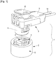
- the set of connectors 1 comprises a squib connector 2 and an airbag connector 3 forming a counter-connector.
- the squib connector 2 comprises a bushing 4 housed in a cavity of a metal squib body 5 connected to the ground of the vehicle, and two squib-connector contacts (not shown in the figures). These two contacts are male contacts each comprising a pin housed in a cavity 7 provided in the bushing 4. In this embodiment, each of the male contacts is electrically insulated from the bushing 4.
- the airbag connector 3 comprises a casing 8, a cover 9 and a device 10 for ensuring the position of the connectors (connector position assurance or CPA).
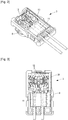
- the airbag connector 3 furthermore comprises a ferrite block 11, and first and second female contacts 12 that are each respectively designed to couple with a male contact of the squib connector 2.
- the airbag connector 3 also comprises a third contact 20.
- the first and second contacts 12 are each electrically connected to a control circuit, via electrical wires 13.
- the first and second contacts 12 and third contact 20 each respectively consist of a conductive metal strip that was cut from a metal sheet, then folded and/or rolled. Each of the first and second contacts 12 and third contact 20 are of a single piece.
- the ferrite block 11 for example has a resistivity comprised between 10 7 and 10 9 ohms.
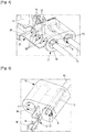
- the ferrite block 11 comprises two parallel passages 6 that extend longitudinally between a front aperture 18 and a rear aperture 19 (the terms “front” and “rear” corresponding, in this document, to the front portion of the airbag connector 3, which portion is coupled to the squib connector 2, and to the far-end portion, via which the electrical wires 13 exit from the airbag connector 3, respectively).
- the first and second contacts 12 of the airbag connector 3 each comprise a contact segment 14 for establishing an electrical contact with a contact of the squib connector 2, a crimping segment 15 for making an electrical connection to the control circuit, a short-circuit contact 16 and an elastic strip 17.
- the crimping segments 15 and the elastic strip 17 of each of the contacts 12 are each respectively inserted via the front aperture 18 of a passage 6 provided in the ferrite block 11.
- each elastic strip 17 of each of the first and second contacts 12 has a lyre shape.
- each elastic strip 17 comprises two tongues 21 that extend essentially parallel to each other, between a supporting segment 22 common to both tongues 21, and a free end 23.
- the supporting segment 22 is folded to 180° with respect to an intermediate segment 24, from which the crimping segment 15 extends.
- the tongues 21 and the crimping segment 15 are each folded from the supporting segment 22 and from the intermediate segment 24, respectively.
- the tongues 21 extend longitudinally above the crimping segment 15.
- Each tongue 21 comprises one tooth 25 that extends transversely with respect to the longitudinal direction of the tongues 21.
- Each tooth 25 has a contact surface 27 intended to make contact with the interior surface of a passage 6 provided in the ferrite block 11.
- the tongues 21 are separated by a slit 26. The tongues 21 may move closer to each other elastically, in the space provided by the slit 26, but tend to return elastically to a rest position in which they exert a contact force via the contact surface 27 of each tooth 25.
- Each elastic strip 17 comprises two surfaces 27 of contact with the ferrite block 11.
- the two contacts 12 make contact with the ferrite block 11 (but in variants, just one of the first and second contacts 12 could make contact with the ferrite block).
- the third contact 20 comprises four elastic tongues 28 extending from a common segment 29. Each of these tongues 28 is shaped to bear against the external surface of the ferrite block 11.
- the third contact 20 comprises a plurality of points of contact (for example four points of contact) with the ferrite block 11, in order to improve the electrical continuity between the third contact 20 and the ferrite block 11.
- connection assembly 1 To mount a connection assembly 1 according to the embodiment described above or its variants,
Landscapes
- Air Bags (AREA)
- Details Of Connecting Devices For Male And Female Coupling (AREA)
Abstract
Description
- The invention relates to the field of motor-vehicle connection systems and more particularly to the field of connection systems for passive motor-vehicle safety devices such as airbags, safety belt pre-tensioners, etc., i.e. for the devices referred to as SRSs (safety restraint systems).
- In this field, passive safety devices may comprise gas-generating squibs that are fired electronically. In this case, the squib comprises a squib connector, itself coupled to an airbag connector. Throughout this document, the generic term "airbag connector" will be used to refer to a connector connected, via electrical wires, to a control device that triggers a squib, irrespectively of whether the squib is a squib intended to inflate an airbag, to pre-tension a safety belt, or to do something else.
- When a shock exceeds a set acceleration or deceleration threshold, the squib is triggered by the control device, which is programmed to send a signal to the squib to which it is connected, via electrical wires and an airbag connector. The explosion that results engenders a sudden combustion that induces a high gas pressure in a piston (pre-tensioner) or an inflatable bag (airbag).
- It is important to take care to ensure that squibs do not trigger in the absence of a suitable command. In order to avoid untimely triggering, it has already been proposed to filter, for example with ferrites, electrical signals transmitted by the electrical wires connected to a squib and that are not generated by the control device but rather by electromagnetic interference. Specifically, electromagnetic interference is generated in frequency ranges that are generally well filtered by ferrites placed in an airbag connector connected to the electrical wires and coupled to the connector of the squib.
- Reference may for example be made to
EP1009070A2 ,US20130241281A1 orUS20130309884 A1 for a description of a connector of this type. - However, a squib could also trigger under the effect of an electrostatic discharge, especially at the moment at which the airbag connector is coupled to the connector of the squib. In order to avoid this, it has been proposed to equip airbag connectors with a device that short-circuits the contacts of the airbag connector provided that the latter is not coupled to the connector of the squib and that opens during the coupling of these connectors. Reference may for example be made to document
EP3116075A1 for a description of a connector of this type. - Another contribution to the improvement of the protection against potential electrostatic discharges of connection assemblies for passive safety devices as mentioned above is proposed below.
- More particularly, a connector according to
Claim 1 is proposed. - By virtue of these provisions, potential electric charge generated, for example, via electrostatic effects in the wires connecting the control device to the airbag connector may be transmitted to the squib body, which itself is connected to ground, by way of the ground contact of the squib, of the third contact and of the ferrite block. It is therefore evacuated without accumulating and without risk of the squib being triggered, during a discharge.
- This connector potentially also comprises one or more of the features of
Claims 2 to 5, considered alone or in combination with one or more others. - According to another aspect, the invention relates to a connection assembly according to
Claim 6 for a passive motor-vehicle safety device. - This connection assembly potentially also comprises one or more of the features of
Claims 7 to 9, considered alone or in combination with one or more others. - According to yet another aspect, the invention relates to a method according to
Claim 10 for mounting a connection assembly for a motor-vehicle safety device. - Other features, aims and advantages of the aforementioned connection assembly will become apparent on reading the following detailed description, and with reference to the appended drawings, which are given by way of non-limiting example, and in which:
- [
Fig. 1 ] schematically shows in perspective an exemplary embodiment of a set of connectors; - [
Fig. 2 ] schematically shows in perspective, without its cover, the airbag connector of the set of connectors that is illustrated inFigure 1 ; this figure especially shows first and second contacts passing through a ferrite block, and a third contact; - [
Fig. 3 ] schematically shows, seen from above, without the cover, the airbag connector illustrated inFigure 2 ; - [
Fig. 4 ] is a schematic representation in perspective of the third contact being brought into contact with the ferrite block shown inFigure 2 ; - [
Fig. 5 ] is a schematic representation in perspective of one of the first and second contacts shown inFigure 2 being brought into contact with the ferrite block; - [
Fig. 6 ] is a schematic representation in perspective of a pair of elastic strips of one of the first and second contacts; - [
Fig. 7 ] is a schematic representation in lateral elevation of the pair of strips illustrated inFigure 6 ; - [
Fig. 8 ] is a schematic representation seen from above of the pair of strips illustrated inFigures 6 and 7 . - An exemplary embodiment of a set of
connectors 1 for a passive motor-vehicle safety device is described below. - In this embodiment, the set of
connectors 1 comprises asquib connector 2 and anairbag connector 3 forming a counter-connector. - The
squib connector 2 comprises a bushing 4 housed in a cavity of ametal squib body 5 connected to the ground of the vehicle, and two squib-connector contacts (not shown in the figures). These two contacts are male contacts each comprising a pin housed in acavity 7 provided in the bushing 4. In this embodiment, each of the male contacts is electrically insulated from the bushing 4. - As shown in
Figure 1 , theairbag connector 3 comprises acasing 8, acover 9 and adevice 10 for ensuring the position of the connectors (connector position assurance or CPA). - As shown in
Figures 2 and 3 , theairbag connector 3 furthermore comprises aferrite block 11, and first and secondfemale contacts 12 that are each respectively designed to couple with a male contact of thesquib connector 2. Theairbag connector 3 also comprises athird contact 20. The first andsecond contacts 12 are each electrically connected to a control circuit, viaelectrical wires 13. - The first and
second contacts 12 andthird contact 20 each respectively consist of a conductive metal strip that was cut from a metal sheet, then folded and/or rolled. Each of the first andsecond contacts 12 andthird contact 20 are of a single piece. - The
ferrite block 11 for example has a resistivity comprised between 107 and 109 ohms. - As shown in
Figures 4 and 5 , theferrite block 11 comprises twoparallel passages 6 that extend longitudinally between afront aperture 18 and a rear aperture 19 (the terms "front" and "rear" corresponding, in this document, to the front portion of theairbag connector 3, which portion is coupled to thesquib connector 2, and to the far-end portion, via which theelectrical wires 13 exit from theairbag connector 3, respectively). - The first and
second contacts 12 of theairbag connector 3 each comprise acontact segment 14 for establishing an electrical contact with a contact of thesquib connector 2, acrimping segment 15 for making an electrical connection to the control circuit, a short-circuit contact 16 and anelastic strip 17. Thecrimping segments 15 and theelastic strip 17 of each of thecontacts 12 are each respectively inserted via thefront aperture 18 of apassage 6 provided in theferrite block 11. - As shown in
Figures 5 to 8 , theelastic strip 17 of each of the first andsecond contacts 12 has a lyre shape. In other words, eachelastic strip 17 comprises twotongues 21 that extend essentially parallel to each other, between a supportingsegment 22 common to bothtongues 21, and afree end 23. The supportingsegment 22 is folded to 180° with respect to anintermediate segment 24, from which thecrimping segment 15 extends. Thetongues 21 and thecrimping segment 15 are each folded from the supportingsegment 22 and from theintermediate segment 24, respectively. Thetongues 21 extend longitudinally above thecrimping segment 15. Eachtongue 21 comprises onetooth 25 that extends transversely with respect to the longitudinal direction of thetongues 21. Eachtooth 25 has acontact surface 27 intended to make contact with the interior surface of apassage 6 provided in theferrite block 11. Thetongues 21 are separated by aslit 26. Thetongues 21 may move closer to each other elastically, in the space provided by theslit 26, but tend to return elastically to a rest position in which they exert a contact force via thecontact surface 27 of eachtooth 25. - Each
elastic strip 17 comprises twosurfaces 27 of contact with theferrite block 11. In the embodiment described here, the twocontacts 12 make contact with the ferrite block 11 (but in variants, just one of the first andsecond contacts 12 could make contact with the ferrite block). - As shown in
Figure 4 , thethird contact 20 comprises fourelastic tongues 28 extending from acommon segment 29. Each of thesetongues 28 is shaped to bear against the external surface of theferrite block 11. Thethird contact 20 comprises a plurality of points of contact (for example four points of contact) with theferrite block 11, in order to improve the electrical continuity between thethird contact 20 and theferrite block 11. - Thus, potential electric charge generated via electrostatic effects, via removal from or addition to at least one of the first and second contacts, is removed via the
tongues 21 of theelastic strips 17, to theferrite block 11, then via thethird contact 20, to the ground of the vehicle. These arrangements protect the squib and prevent it from triggering because of an electrostatic discharge, since electric charge cannot accumulate in a sufficient amount to create a sufficient potential difference, notably between the contacts of thesquib connector 2. - To mount a
connection assembly 1 according to the embodiment described above or its variants, - a squib comprising a ground contact and a
squib body 5 that is electrically conductive and connected to the ground of the vehicle is provided; - a counter-connector 3 comprising a
casing 8 in which are housed aferrite block 11, first andsecond contacts 12, and athird contact 10 is provided; and - the first and
second contacts 12 are electrically connected to the ground of the vehicle by way of the ground contact of the squib, of thethird contact 20 and of theferrite block 11.
Claims (10)
- Connector for a passive motor-vehicle safety device, this connector comprising a casing (8) in which are housed a ferrite block (11), first and second contacts (12) each comprising a segment (15) extending into a passage (6) provided in the ferrite block (11), and a third contact (20),
characterized in that the third contact (20) and at least one of the first and second contacts (12) make contact with the ferrite block (11). - Connector according to Claim 1, wherein at least one of the first and second contacts (12) makes contact with an internal wall of a passage (6) provided in the ferrite block (11), and the third contact (20) makes contact with an external wall of the ferrite block (11).
- Connector according to either of Claims 1 and 2, wherein the third contact (20) comprises a plurality of points of contact with the ferrite block (11).
- Connector according to one of Claims 1 to 3, wherein at least one of the first and second contacts (12) comprises at least one elastic strip (17) comprising at least one point of contact (27) with the ferrite block (11).
- Connector according to one of Claims 1 to 4, wherein the ferrite block (11) is made of a material having a resistivity per unit area comprised between 107 and 109 ohms.
- Connection assembly for a passive motor-vehicle safety device, this assembly comprising, on the one hand, a squib connector (2) housed in an electrically conductive, metal squib body (5) and connected to the ground of the vehicle and, on the other hand, a counter-connector (3), forming a connector according to one of Claims 1 to 5, and coupled to the squib connector (2), wherein the squib connector (2) comprises two contacts that are electrically connected to the squib and a ground contact that is electrically connected to the ground of the vehicle.
- Assembly according to Claim 6, wherein the first and second contacts (12) make contact with the ferrite block (11).
- Assembly according to either of Claims 6 and 7, wherein at least one of the first and second contacts (12) comprises at least one elastic strip (17) comprising at least one point of contact (27) with the ferrite block (11).
- Assembly according to one of Claims 6 to 8, wherein the third contact (20) comprises a plurality of points of contact with the ferrite block (11).
- Method for mounting a connection assembly for a motor-vehicle safety device, wherein:- a squib comprising a squib connector (2) comprising a ground contact connected to the ground of the vehicle is provided;- a counter-connector (3) comprising a casing (8) in which are housed a ferrite block (11), first and second contacts (12), and a third contact (20) is provided;
characterized in that at least one of the first and second contacts (12) is electrically connected to the ground of the vehicle by way of the ground contact of the squib, of the third contact (20) and of the ferrite block (11).
Applications Claiming Priority (1)
| Application Number | Priority Date | Filing Date | Title |
|---|---|---|---|
| FR1909790A FR3100667B1 (en) | 2019-09-05 | 2019-09-05 | Connection assembly for passive safety device, protected against electrostatic discharges |
Publications (1)
| Publication Number | Publication Date |
|---|---|
| EP3790123A1 true EP3790123A1 (en) | 2021-03-10 |
Family
ID=68425123
Family Applications (1)
| Application Number | Title | Priority Date | Filing Date |
|---|---|---|---|
| EP20194429.5A Pending EP3790123A1 (en) | 2019-09-05 | 2020-09-03 | Connection assembly for a passive safety device and that is protected against electrostatic discharges |
Country Status (2)
| Country | Link |
|---|---|
| EP (1) | EP3790123A1 (en) |
| FR (1) | FR3100667B1 (en) |
Citations (5)
| Publication number | Priority date | Publication date | Assignee | Title |
|---|---|---|---|---|
| EP1009070A2 (en) | 1998-12-07 | 2000-06-14 | Framatome Connectors International | Filtered electrical connector with multiple ferrite members |
| US20050020136A1 (en) * | 2003-07-23 | 2005-01-27 | Johannes Richard A. | Electrical connector contact |
| US20130241281A1 (en) | 2010-07-29 | 2013-09-19 | Fci Automotive Holding | Electrical circuit and method of manufacturing said electrical circuit |
| US20130309884A1 (en) | 2011-02-01 | 2013-11-21 | Tyco Electronics France Sas | Electrical connector for a safety restraint system having a ground contact |
| EP3116075A1 (en) | 2015-07-08 | 2017-01-11 | Delphi Technologies, Inc. | Electrical plug connector for a safety restraint system |
-
2019
- 2019-09-05 FR FR1909790A patent/FR3100667B1/en active Active
-
2020
- 2020-09-03 EP EP20194429.5A patent/EP3790123A1/en active Pending
Patent Citations (5)
| Publication number | Priority date | Publication date | Assignee | Title |
|---|---|---|---|---|
| EP1009070A2 (en) | 1998-12-07 | 2000-06-14 | Framatome Connectors International | Filtered electrical connector with multiple ferrite members |
| US20050020136A1 (en) * | 2003-07-23 | 2005-01-27 | Johannes Richard A. | Electrical connector contact |
| US20130241281A1 (en) | 2010-07-29 | 2013-09-19 | Fci Automotive Holding | Electrical circuit and method of manufacturing said electrical circuit |
| US20130309884A1 (en) | 2011-02-01 | 2013-11-21 | Tyco Electronics France Sas | Electrical connector for a safety restraint system having a ground contact |
| EP3116075A1 (en) | 2015-07-08 | 2017-01-11 | Delphi Technologies, Inc. | Electrical plug connector for a safety restraint system |
Also Published As
| Publication number | Publication date |
|---|---|
| FR3100667B1 (en) | 2023-12-08 |
| FR3100667A1 (en) | 2021-03-12 |
Similar Documents
| Publication | Publication Date | Title |
|---|---|---|
| US6893277B2 (en) | Squib connector assembly with CPA | |
| EP3116075B1 (en) | Electrical plug connector for a safety restraint system | |
| EP0591948B1 (en) | Electrical connection system with safety interlock | |
| US10236640B2 (en) | Electrical connector for a safety restraint system | |
| CN102460851A (en) | Connector for a safety restraint system | |
| EP3118943B1 (en) | Electrical plug connector for a safety restraint system and connection method thereof. | |
| EP2380244B1 (en) | Shorting clip for an airbag ignition system | |
| JPH02117453A (en) | Connector for air bag | |
| EP1891707B1 (en) | An electrical connector assembly for an airbag ignitor | |
| EP3035451B1 (en) | Grounding clip for an airbag ignition system | |
| WO2010026449A1 (en) | Sealable squib connector | |
| US20130241281A1 (en) | Electrical circuit and method of manufacturing said electrical circuit | |
| US20150219708A1 (en) | Connector for a safety restraint system | |
| EP3240116B1 (en) | Plug connector | |
| EP3790125A1 (en) | Passive safety-device connection assembly protected against electrical discharges, socket, airbag connector and method for mounting a connection assembly | |
| US20200266589A1 (en) | Connector-integrated grounding systems and methods | |
| EP2838765B1 (en) | Low-profile igniter assemblies adapted for use with inflatable airbag systems | |
| FR3100667A1 (en) | Connection set for passive safety device, protected against electrostatic discharges | |
| EP3813206A1 (en) | Connection assembly for a passive security device, protected against electrostatic discharges | |
| KR100224217B1 (en) | Air bag connector |
Legal Events
| Date | Code | Title | Description |
|---|---|---|---|
| PUAI | Public reference made under article 153(3) epc to a published international application that has entered the european phase |
Free format text: ORIGINAL CODE: 0009012 |
|
| STAA | Information on the status of an ep patent application or granted ep patent |
Free format text: STATUS: THE APPLICATION HAS BEEN PUBLISHED |
|
| AK | Designated contracting states |
Kind code of ref document: A1 Designated state(s): AL AT BE BG CH CY CZ DE DK EE ES FI FR GB GR HR HU IE IS IT LI LT LU LV MC MK MT NL NO PL PT RO RS SE SI SK SM TR |
|
| AX | Request for extension of the european patent |
Extension state: BA ME |
|
| STAA | Information on the status of an ep patent application or granted ep patent |
Free format text: STATUS: REQUEST FOR EXAMINATION WAS MADE |
|
| 17P | Request for examination filed |
Effective date: 20210903 |
|
| RBV | Designated contracting states (corrected) |
Designated state(s): AL AT BE BG CH CY CZ DE DK EE ES FI FR GB GR HR HU IE IS IT LI LT LU LV MC MK MT NL NO PL PT RO RS SE SI SK SM TR |
|
| STAA | Information on the status of an ep patent application or granted ep patent |
Free format text: STATUS: EXAMINATION IS IN PROGRESS |
|
| 17Q | First examination report despatched |
Effective date: 20230103 |
|
| RAP3 | Party data changed (applicant data changed or rights of an application transferred) |
Owner name: APTIV TECHNOLOGIES LIMITED |
|
| RAP1 | Party data changed (applicant data changed or rights of an application transferred) |
Owner name: APTIV TECHNOLOGIES AG |
|
| RIC1 | Information provided on ipc code assigned before grant |
Ipc: H01R 13/648 20060101AFI20260302BHEP Ipc: H01R 13/7193 20110101ALI20260302BHEP Ipc: H01R 13/7197 20110101ALI20260302BHEP Ipc: H01R 13/703 20060101ALN20260302BHEP Ipc: H01R 103/00 20060101ALN20260302BHEP |
|
| GRAP | Despatch of communication of intention to grant a patent |
Free format text: ORIGINAL CODE: EPIDOSNIGR1 |
|
| STAA | Information on the status of an ep patent application or granted ep patent |
Free format text: STATUS: GRANT OF PATENT IS INTENDED |