EP3790077B1 - Sekundärbatterie - Google Patents
Sekundärbatterie Download PDFInfo
- Publication number
- EP3790077B1 EP3790077B1 EP19796894.4A EP19796894A EP3790077B1 EP 3790077 B1 EP3790077 B1 EP 3790077B1 EP 19796894 A EP19796894 A EP 19796894A EP 3790077 B1 EP3790077 B1 EP 3790077B1
- Authority
- EP
- European Patent Office
- Prior art keywords
- cap
- vent
- secondary battery
- extension part
- region
- Prior art date
- Legal status (The legal status is an assumption and is not a legal conclusion. Google has not performed a legal analysis and makes no representation as to the accuracy of the status listed.)
- Active
Links
Images


Classifications
-
- H—ELECTRICITY
- H01—ELECTRIC ELEMENTS
- H01M—PROCESSES OR MEANS, e.g. BATTERIES, FOR THE DIRECT CONVERSION OF CHEMICAL ENERGY INTO ELECTRICAL ENERGY
- H01M50/00—Constructional details or processes of manufacture of the non-active parts of electrochemical cells other than fuel cells, e.g. hybrid cells
- H01M50/30—Arrangements for facilitating escape of gases
- H01M50/342—Non-re-sealable arrangements
- H01M50/3425—Non-re-sealable arrangements in the form of rupturable membranes or weakened parts, e.g. pierced with the aid of a sharp member
-
- H—ELECTRICITY
- H01—ELECTRIC ELEMENTS
- H01M—PROCESSES OR MEANS, e.g. BATTERIES, FOR THE DIRECT CONVERSION OF CHEMICAL ENERGY INTO ELECTRICAL ENERGY
- H01M50/00—Constructional details or processes of manufacture of the non-active parts of electrochemical cells other than fuel cells, e.g. hybrid cells
- H01M50/30—Arrangements for facilitating escape of gases
- H01M50/342—Non-re-sealable arrangements
-
- B—PERFORMING OPERATIONS; TRANSPORTING
- B23—MACHINE TOOLS; METAL-WORKING NOT OTHERWISE PROVIDED FOR
- B23K—SOLDERING OR UNSOLDERING; WELDING; CLADDING OR PLATING BY SOLDERING OR WELDING; CUTTING BY APPLYING HEAT LOCALLY, e.g. FLAME CUTTING; WORKING BY LASER BEAM
- B23K26/00—Working by laser beam, e.g. welding, cutting or boring
- B23K26/20—Bonding
- B23K26/21—Bonding by welding
-
- H—ELECTRICITY
- H01—ELECTRIC ELEMENTS
- H01M—PROCESSES OR MEANS, e.g. BATTERIES, FOR THE DIRECT CONVERSION OF CHEMICAL ENERGY INTO ELECTRICAL ENERGY
- H01M50/00—Constructional details or processes of manufacture of the non-active parts of electrochemical cells other than fuel cells, e.g. hybrid cells
- H01M50/10—Primary casings; Jackets or wrappings
- H01M50/102—Primary casings; Jackets or wrappings characterised by their shape or physical structure
- H01M50/107—Primary casings; Jackets or wrappings characterised by their shape or physical structure having curved cross-section, e.g. round or elliptic
-
- H—ELECTRICITY
- H01—ELECTRIC ELEMENTS
- H01M—PROCESSES OR MEANS, e.g. BATTERIES, FOR THE DIRECT CONVERSION OF CHEMICAL ENERGY INTO ELECTRICAL ENERGY
- H01M50/00—Constructional details or processes of manufacture of the non-active parts of electrochemical cells other than fuel cells, e.g. hybrid cells
- H01M50/10—Primary casings; Jackets or wrappings
- H01M50/147—Lids or covers
- H01M50/148—Lids or covers characterised by their shape
- H01M50/152—Lids or covers characterised by their shape for cells having curved cross-section, e.g. round or elliptic
-
- H—ELECTRICITY
- H01—ELECTRIC ELEMENTS
- H01M—PROCESSES OR MEANS, e.g. BATTERIES, FOR THE DIRECT CONVERSION OF CHEMICAL ENERGY INTO ELECTRICAL ENERGY
- H01M50/00—Constructional details or processes of manufacture of the non-active parts of electrochemical cells other than fuel cells, e.g. hybrid cells
- H01M50/10—Primary casings; Jackets or wrappings
- H01M50/147—Lids or covers
- H01M50/166—Lids or covers characterised by the methods of assembling casings with lids
- H01M50/169—Lids or covers characterised by the methods of assembling casings with lids by welding, brazing or soldering
-
- H—ELECTRICITY
- H01—ELECTRIC ELEMENTS
- H01M—PROCESSES OR MEANS, e.g. BATTERIES, FOR THE DIRECT CONVERSION OF CHEMICAL ENERGY INTO ELECTRICAL ENERGY
- H01M50/00—Constructional details or processes of manufacture of the non-active parts of electrochemical cells other than fuel cells, e.g. hybrid cells
- H01M50/10—Primary casings; Jackets or wrappings
- H01M50/172—Arrangements of electric connectors penetrating the casing
-
- H—ELECTRICITY
- H01—ELECTRIC ELEMENTS
- H01M—PROCESSES OR MEANS, e.g. BATTERIES, FOR THE DIRECT CONVERSION OF CHEMICAL ENERGY INTO ELECTRICAL ENERGY
- H01M50/00—Constructional details or processes of manufacture of the non-active parts of electrochemical cells other than fuel cells, e.g. hybrid cells
- H01M50/50—Current conducting connections for cells or batteries
- H01M50/572—Means for preventing undesired use or discharge
- H01M50/574—Devices or arrangements for the interruption of current
- H01M50/578—Devices or arrangements for the interruption of current in response to pressure
-
- H—ELECTRICITY
- H01—ELECTRIC ELEMENTS
- H01M—PROCESSES OR MEANS, e.g. BATTERIES, FOR THE DIRECT CONVERSION OF CHEMICAL ENERGY INTO ELECTRICAL ENERGY
- H01M50/00—Constructional details or processes of manufacture of the non-active parts of electrochemical cells other than fuel cells, e.g. hybrid cells
- H01M50/50—Current conducting connections for cells or batteries
- H01M50/572—Means for preventing undesired use or discharge
- H01M50/584—Means for preventing undesired use or discharge for preventing incorrect connections inside or outside the batteries
- H01M50/59—Means for preventing undesired use or discharge for preventing incorrect connections inside or outside the batteries characterised by the protection means
- H01M50/593—Spacers; Insulating plates
-
- B—PERFORMING OPERATIONS; TRANSPORTING
- B23—MACHINE TOOLS; METAL-WORKING NOT OTHERWISE PROVIDED FOR
- B23K—SOLDERING OR UNSOLDERING; WELDING; CLADDING OR PLATING BY SOLDERING OR WELDING; CUTTING BY APPLYING HEAT LOCALLY, e.g. FLAME CUTTING; WORKING BY LASER BEAM
- B23K2101/00—Articles made by soldering, welding or cutting
- B23K2101/36—Electric or electronic devices
-
- H—ELECTRICITY
- H01—ELECTRIC ELEMENTS
- H01M—PROCESSES OR MEANS, e.g. BATTERIES, FOR THE DIRECT CONVERSION OF CHEMICAL ENERGY INTO ELECTRICAL ENERGY
- H01M2200/00—Safety devices for primary or secondary batteries
- H01M2200/20—Pressure-sensitive devices
-
- Y—GENERAL TAGGING OF NEW TECHNOLOGICAL DEVELOPMENTS; GENERAL TAGGING OF CROSS-SECTIONAL TECHNOLOGIES SPANNING OVER SEVERAL SECTIONS OF THE IPC; TECHNICAL SUBJECTS COVERED BY FORMER USPC CROSS-REFERENCE ART COLLECTIONS [XRACs] AND DIGESTS
- Y02—TECHNOLOGIES OR APPLICATIONS FOR MITIGATION OR ADAPTATION AGAINST CLIMATE CHANGE
- Y02E—REDUCTION OF GREENHOUSE GAS [GHG] EMISSIONS, RELATED TO ENERGY GENERATION, TRANSMISSION OR DISTRIBUTION
- Y02E60/00—Enabling technologies; Technologies with a potential or indirect contribution to GHG emissions mitigation
- Y02E60/10—Energy storage using batteries
Definitions
- the present invention relates to a secondary battery.
- a secondary battery is a chargeable and dischargeable battery, unlike a primary battery that is not chargeable.
- Low-capacity secondary batteries are used in portable small electronic devices such as smart phones, feature phones, notebook computers, digital cameras, and camcorders, and large-capacity secondary batteries are widely used for a power source and power storage for driving a motor, such as hybrid vehicles, electric vehicles, and the like.
- Such lithium ion secondary batteries may be classified into cylindrical, prismatic, and pouch-type secondary batteries.
- a cylindrical lithium ion secondary battery generally includes a cylindrical electrode assembly, a cylindrical case to which the electrode assembly is coupled, an electrolyte injected into the inside of the case to enable movement of lithium ions, and a cap assembly coupled to one side of the case to prevent the electrolyte from leaking and preventing the electrode assembly from being separated.
- KR 2017 0012137 A relates to a cap assembly for a secondary battery.
- the present invention provides a secondary battery capable of improving insulation safety.
- a secondary battery includes: an electrode assembly; a case configured to accommodate the electrode assembly; and a cap assembly coupled to an upper portion of the case, wherein the cap assembly includes a cap-up, a safety vent installed below the cap-up and having a vent extension part extending to an upper side of the cap-up to surround an edge of the cap-up, and an insulation washer attached to upper portions of the vent extension part and the cap-up, and a welding area having a thickness less than that of surroundings is formed on the vent extension part.
- a portion of the safety vent and a portion of the cap-up may be melted by laser welding to form a welding bead, which protrudes upward, on the welding area.
- the welding bead may be spaced apart from the insulation washer.
- the vent extension part may include a first surface that is in contact with the cap-up and a second surface that is an opposite surface of the first surface and is in contact with the insulation washer, and the welding area may be defined by forming a groove having an opened end in the first surface.
- the cap-up may include a terminal part that protrudes upward, a coupling part which is disposed outside the terminal part and to which the safety vent is coupled, and a connection part configured to connect the terminal part to the coupling part, wherein the coupling part may include a first region extending from the connection part and a second region which is disposed outside the first region and has a thickness less than that of the first region and to which the vent extension part is coupled.
- the thickness of the first region may be equal to a sum of the thickness of the second region and a thickness of the vent extension part.
- the insulation washer may be seated on upper portions of the vent extension part and the first region.
- An oxide film may be formed on a surface of the insulation washer.
- the vent extension part may include a first surface that is in contact with the cap-up and a second surface that is an opposite surface of the first surface and is in contact with the insulation washer, and the welding area may be defined by forming a groove having an opened end in the second surface.
- the vent extension part may include a first surface that is in contact with the cap-up and a second surface that is an opposite surface of the first surface and is in contact with the insulation washer, and the welding area may be defined by forming a trench in the second surface.
- the thin welding area may be formed in the safety vent to prevent the welding bead from being in contact with the insulation washer. Therefore, when the gasket is melted or damaged, the short circuit between the cap assembly and the case may be prevented to improve the safety of the secondary battery.
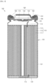
- FIG. 1 is a cross-sectional view of a secondary battery according to an embodiment of the present invention.
- a secondary battery 100 includes an electrode assembly 110, a case 120, a cap assembly 130, and a gasket 190.
- the electrode assembly 110 includes a first electrode 111, a second electrode 112, and a separator 113 interposed between the first electrode 111 and the second electrode 112.
- the electrode assembly 110 may be formed by winding a stack of the first electrode 111, the separator 113, and the second electrode 112 in a jelly-roll form.
- the first electrode 111 may function as a positive electrode
- the second electrode 112 may function as a negative electrode.
- a first electrode tab 114 is connected to the cap assembly 130 in an upper portion of the electrode assembly 110
- a second electrode tab 115 is connected to a bottom plate 122 of the case 120 in a lower portion of the electrode assembly 110.
- the first electrode 111 is formed by applying a first electrode active material such as a transition metal oxide on a first electrode collector formed of metal foil such as aluminum foil.
- a first electrode non-coating portion that is not coated with a first electrode active material is formed on the first electrode 111, and a first electrode tab 114 is attached to the first electrode non-coating portion.
- the first electrode tab 114 has one end, which is electrically connected to the first electrode 111, and the other end, which protrudes upward from the electrode assembly 110 and is electrically connected to the cap assembly 130.
- the second electrode 112 is formed by applying a second electrode active material such as graphite or carbon on a second electrode collector made of metal foil such as copper or nickel.
- a second electrode non-coating portion that is not coated with a second electrode active material is formed on the second electrode 112, and a second electrode tab 115 is attached to the second electrode non-coating portion.
- the second electrode tab 115 has one end, which is electrically connected to the second electrode 112, and the other end, which protrudes downward from the electrode assembly 110 and is electrically connected to the bottom plate 122 of the case 120.
- the separator 113 is disposed between the first electrode 111 and the second electrode 112 to prevent short circuit from occurring and allow lithium ions to be movable.
- the separator 113 may be formed of polyethylene, polypropylene, or a composite film of polyethylene and polypropylene.
- the case 120 includes a side plate 121, which is a cylindrical body having a predetermined diameter to form a space in which the electrode assembly 110 is accommodated, and a bottom plate 122 that seals a lower portion of the side plate 121.
- An upper opening of the case 120 is opened to be sealed after inserting the electrode assembly 110.
- a beading part 123 for preventing movement of the electrode assembly 110 is formed at an upper portion of the case 120.
- a crimping part 124 for fixing the cap assembly 130 and the gasket 190 is formed at the uppermost end of the case 120.
- the crimping part 124 has a gasket 190 interposed therein and is formed to press the cap assembly 130, thereby preventing the cap assembly 130 from being separated and preventing the electrolyte from leaking.
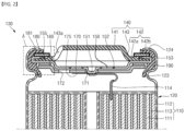
- FIG. 2 is a cross-sectional view of the cap assembly in the secondary battery according to an embodiment of the present invention.
- the cap assembly 130 includes a cap-up 140, a safety vent 150, an insulator 160, a cap-down 170, and an insulation washer 180.
- the cap-up 140 is provided as a circular plate body and includes a terminal part 141 convexly formed at a center thereof, a coupling part 142 disposed on an outer circumference of the terminal part 141, and a connection part 143 connecting the terminal part 141 and the coupling part 142 to each other.
- the terminal part 141 protrudes upward rather than the coupling part 142 to serve as a terminal electrically connected to an external circuit.
- the terminal part 141 is electrically connected to the first electrode tab 114 to function as, for example, a positive electrode.
- the coupling part 142 is disposed on the outer circumference of the terminal part 141, and the safety vent 150 is coupled to the coupling part 142.
- the coupling part 142 includes a first region 142a disposed inside and connected to the connection part 143 and a second region 142b disposed outside the first region 142a.
- the second region 142b is formed to be thinner than a thickness of the first region 142a, and thus, a stepped portion occurs between the first region 142a and the second region 142b.
- a vent extension part 153 of the safety vent 150 is coupled to an upper portion of the second region 142b.
- a sum of a thickness of the second region 142b and a thickness of the vent extension part 153 is formed to be equal to the thickness of the first region 142a.
- connection part 143 connects the terminal part 141 and the coupling part 142 to each other, and a gas discharge hole 143a is formed in the connection part 143.
- the gas discharge hole 143a may be formed in plurality in the connection part 143 and provide a passage through which a gas generated inside the case 120 is discharged. Also, a portion of the gas discharge hole 143a may extend to the terminal part 141 and the coupling part 142.
- the safety vent 150 is provided as a circular plate body corresponding to the cap-up 140 and is coupled to a lower portion of the cup-up 140.
- a protrusion 151 protruding downward is formed at a center of the safety vent 150.
- the safety vent 150 is electrically connected to the sub plate 175 fixed to a lower surface of the cap-down 170 by using the protrusion 151 passing through a through-hole 171 of the cap-down 170.
- the sub plate 175 and the protrusion 151 of the safety vent 150 may be welded through laser welding, ultrasonic welding, resistance welding, or an equivalent method thereof.
- a notch 152 for guiding rupture of the safety vent 150 is formed on the outer circumference of the protrusion 151.
- the safety vent 150 discharges the internal gas while blocking current when an abnormal internal pressure occurs in the case 120.
- the protrusion 151 ascends upward by the gas discharged through the gas discharge hole 172 of the cap-down 170 and thus is electrically separated from the sub plate 175.
- the sub plate 175 is electrically separated from the safety vent 150 while the welded portion of the protrusion 151 is torn.
- the safety vent 150 may be made of aluminum (Al).
- the safety vent 150 is installed in close contact with the coupling part 142 at the lower portion of the cup-up 140. Also, an edge of the safety vent 150 surrounds the cup-up 140 to extend to an upper side of the cup-up 140.
- the upward extending portion of the cap-up 140 is defined as a vent extension part 153.
- an upper portion of the vent extension part 153 is welded using laser to fix the safety vent 150 to the cap-up 140. A portion of the safety vent 150 and a portion of the cap-up 140 are melted by the laser welding to form a welding bead 155. The welding method of the safety vent 150 and the cap-up 140 and the welding bead 155 will be described in more detail below.
- the insulator 160 is interposed between the safety vent 150 and the cap-down 170 to insulate the safety vent 150 and the cap-down 170 from each other.
- the insulator 160 is provided in a ring shape and is interposed between an outer circumference of the safety vent 150 and an outer circumference of the cap-down 170.
- the insulator 160 may be made of a resin material such as polyethylene (PE), polypropylene (PP), polyethylene terephthalate (PET), or the like.
- the cap-down 170 is provided as a circular plate body.
- the through-hole 171 is formed in a center of the cap-down 170, and the protrusion 151 of the safety vent 150 passes through the through-hole 171.
- the gas discharge hole 172 is formed at one side of the cap-down 170, and a sub plate 175 is coupled to a lower portion of the cap-down 170.
- the gas discharge hole 172 serves to discharge the internal gas when an excessive internal pressure is generated in the case 120.
- the protrusion 151 of the safety vent 150 may ascend by the gas discharged through the gas discharge hole 172, and thus, the protrusion 151 may be separated from the sub plate 175.
- the sub plate 175 is welded between the protrusion 151 of the safety vent 150, which passes through the through-hole 171 of the cap-down 170, and the first electrode tab 114. Accordingly, the sub plate 175 electrically connects the first electrode tab 114 to the safety vent 150.
- the insulation washer 180 is provided in a ring shape and is installed on the upper portions of the cap-up 140 and the safety vent 150. Particularly, the insulation washer 180 is disposed on the upper portions of the first region 142a of the cap-up 140 and the vent extension part 153 of the safety vent 150. Here, the insulation washer 180 may be attached to the upper portions of the cap-up 140 and the safety vent 150 through an adhesive member (not shown).
- the insulation washer 180 serves to prevent an electrical short-circuit between the cap assembly 110 and the case 120. Particularly, the insulation washer 180 may prevent the cap assembly 110 and the case 120 from being short-circuited even if the gasket 190 disposed between the cap assembly 110 and the case 120 is melted or damaged.
- the insulation washer 180 may be formed by anodizing an aluminum sheet.
- the anodizing is to oxidize a surface of a metal plate so as to form an oxide film.
- the most representative material for anodizing is aluminum (Al).
- the anodizing may be performed on metal materials such as manganese (Mn), zinc (Zn), titanium (Ti), hafnium (Hf) and niobium (Nb).
- the oxide film is very hard, has excellent corrosion resistance and abrasion resistance, and is not melted at a high temperature. That is, an oxide film 181 is formed on a surface of the insulation washer 180, and the oxide film 181 prevents an electrical short-circuit between the cap assembly 110 and the case 120.
- the gasket 190 is installed in the upper opening of the case 120. That is, the gasket 190 is assembled by being in close contact with the outer circumference of the cap-up 140, the safety vent 150, and the upper opening of the case 120.
- the gasket 190 may be made of a resin material such as polyethylene (PE), polypropylene (PP), polyethylene terephthalate (PET), or the like.
- the gasket 190 may electrically insulate the case 120 and the cap assembly 130 from each other.
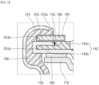
- FIG. 3 is an enlarged cross-sectional view illustrating a portion A of FIG. 2 .
- the vent extension part 153 has a first surface 153a in contact with the cap-up 140 and a second surface 153b in contact with the insulation washer 180 on an opposite surface of the first surface 153a.
- the vent extension part 153 includes a welding area 153c that is welded to the cap-up 140.
- the welding area 153c is formed on an end of the vent extension part 153 and is disposed inside the safety vent 150. That is, the welding area 153c is disposed at a portion adjacent to the first region 142a in the second region 142b of the cap-up 140.
- a thickness of the welding area 153c is formed to be relatively thinner than a thickness of the peripheral vent extension part 153. This is to prevent the welding bead 155 formed when welding the welding area 153c to the cap-up 140 from being in contact with the insulation washer 180.
- the welding area 153c may be defined by forming a groove having an opened end in the first surface 153a of the vent extension part 153. Accordingly, a stepped portion occurs between the vent extension part 153 and the welding area 153c, and a spaced space exists between the welding region 153c and the cap-up 140. During the welding, the welding area 153c is pressed to be in close contact with the second region 142b of the cap-up 140, and then, the safety vent 150 is fixed to the cap-up 140 by irradiating a laser onto the welding area 153c.
- a portion of the welding area 153c and a portion of the second region 142b are melted by the laser welding to form the welding bead 155, and the welding bead 155 protrudes to the upper side of the welding area 153c.
- the welding area 153c is relatively thin compared to the surroundings, the welding area 153c is not in contact with the insulation washer 180 disposed thereon. That is, the welding bead 155 is spaced apart from the insulation washer 180. If the thickness of the welding area is not formed to be thin, the welding bead protrudes to an upper side of the vent extension part and is in contact with the insulation washer.
- the welding bead breaks the oxide film of the insulation washer by a pressure applied when the crimping part is formed to fix the cap assembly to the case. Accordingly, when the gasket is melted or damaged, the short circuit occurs between the cap assembly and the case.
- the welding bead 155 is not in contact with the insulation washer 180 by forming the welding area 153c having the thin thickness in the safety vent 150 to improve safety of the secondary battery 100.
- a secondary battery in which a welding bead is formed on a safety vent having a thin welding area through laser welding, and an insulation washer is attached to an upper portion of the welding bead, was prepared. Also, in Comparative Example, a secondary battery in which a welding bead is formed on a safety vent having the same thickness through laser welding, and an insulation washer is attached to an upper portion of the welding bead was prepared. It was confirmed whether the secondary batteries were electrically connected after short circuit. This process was repeated 6 times.
- the welding area of the safety vent may have the thin thickness to prevent the welding bead and the insulation washer from being in contact with each other, thereby preventing the welding bead and the insulation washer from being electrically re-connected to each other and improving the safety of the secondary battery.
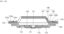
- FIGS. 4A to 4D are cross-sectional views illustrating a method for forming a cap assembly.
- FIGS. 4A to 4D A method for forming a cap assembly in a secondary battery according to the present invention will be described with reference to FIGS. 4A to 4D .
- an insulator 160 and a safety vent 150 are sequentially seated on an upper portion of the cap-down 170, and a sub plate 175 is welded to a protrusion 151 of the safety vent 150, which is exposed through a through-hole of a cap-down 170.
- a cap-up 140 is seated on an upper portion of the safety vent 150.
- the vent extension part 153 extends upward without being bent.
- a welding area 153c is formed on an end of the vent extension part 153.
- a groove having an open end is formed in an inner surface of the welding area 153c, that is, a first surface 153a facing the cap-up 140, and thus, a thickness of the welding area 153c is thinner than that of the surroundings.
- the vent extension part 153 is bent to be in close contact with the upper portion of the cap-up 140. Particularly, the vent extension part 153 is in contact with a second region 142b of a connection part 142 of the cap-up 140.
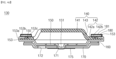
- the welding area 153c is pressed to be in close contact with the second region 142b of the cap-up 140, and the safety vent 150 is fixed to the cap-up 140 through laser welding.
- a welding bead 155 is formed on the welding area 153c through the laser welding. The welding bead 155 is formed by melting a portion of the safety vent 150 and a portion of the cap-up 140 and protrudes to an upper side of the welding area 153c.
- an insulation washer 180 is attached to the upper portions of the cap-up 140 and the safety vent 150.
- the welding area 153c is formed to be thinner than the surroundings, the welding bead 155 formed on the welding area 153c is not in contact with the insulation washer 180.
- the cap assembly 130 is completed, and the completed cap assembly 130 may be coupled and/or fixed together with a gasket 1901 on an upper end of the case 120.
- FIG. 5 is a cross-sectional view illustrating a welding area of a safety vent according to another embodiment of the present invention.
- a safety vent 150 is installed to be in close contact with a coupling part 142 below a cup-up 140 and includes a vent extension part 253 extending to an upper side of the cup-up 140.
- the vent extension part 253 includes a first surface 253a in contact with the cap-up 140 and a second surface 253b in contact with an insulation washer 180 on a surface opposite to the first surface 253a.
- the vent extension part 253 includes a welding area 253c that is welded to the cap-up 140. The welding area 253c is formed on an end of the vent extension part 253 and is disposed inside the safety vent 150.
- the welding area 253c may be defined by forming a groove having an opened end in the second surface 253b of the vent extension part 253. As described above, when the welding area 253c is defined by forming a groove having an open end in the second surface 253b of the vent extension part 253, it is unnecessary to press the welding area 253c when the safety vent 150 and the cap-up 140 are welded to each other.
- FIG. 6 is a cross-sectional view illustrating a welding area of a safety vent according to further another embodiment of the present invention.
- a safety vent 150 is installed to be in close contact with a coupling part 142 below a cup-up 140 and includes a vent extension part 353 extending to an upper side of a cup-up 140.
- the vent extension part 353 has a first surface 353a in contact with the cap-up 140 and a second surface 153b in contact with an insulation washer 180 on an opposite surface of the first surface 353a.
- the vent extension part 353 includes a welding area 353c that is welded to the cap-up 140.
- the welding area 353c may be defined by forming a trench in the second surface 353b of the vent extension part 353. As described above, when the welding area 253c is defined by forming the trench in the second surface 253b of the vent extension part 353, it is unnecessary to press the welding area 353c when a safety vent 150 and a cap-up 140 are welded to each other.
Landscapes
- Chemical & Material Sciences (AREA)
- Chemical Kinetics & Catalysis (AREA)
- Electrochemistry (AREA)
- General Chemical & Material Sciences (AREA)
- Physics & Mathematics (AREA)
- Optics & Photonics (AREA)
- Engineering & Computer Science (AREA)
- Plasma & Fusion (AREA)
- Mechanical Engineering (AREA)
- Gas Exhaust Devices For Batteries (AREA)
- Connection Of Batteries Or Terminals (AREA)
- Sealing Battery Cases Or Jackets (AREA)
Claims (10)
- Sekundärbatterie, die Folgendes umfasst:eine Elektrodenbaugruppe,ein Gehäuse, das dafür konfiguriert ist, die Elektrodenbaugruppe aufzunehmen, undeine Kappenbaugruppe, die an einen oberen Abschnitt des Gehäuses gekoppelt ist,wobei die Kappenbaugruppe eine Kappe, einen Sicherheitsabzug, der unterhalb der Kappe installiert ist und einen Abzugserweiterungsteil aufweist, der sich bis zu einer oberen Seite der Kappe erstreckt, um eine Kante der Kappe zu umgeben, und eine Isolierscheibe, die an oberen Abschnitten des Abzugserweiterungsteils und der Kappe befestigt ist, umfasst undein Schweißbereich, der eine Dicke, geringer als diejenige der Umgebung, aufweist, an dem Abzugserweiterungsteil geformt ist.
- Sekundärbatterie nach Anspruch 1, wobei ein Abschnitt des Sicherheitsabzugs und ein Abschnitt der Kappe durch Laserschweißen geschmolzen sind, um eine Schweißraupe, die nach oben vorspringt, an dem Schweißbereich zu formen.
- Sekundärbatterie nach Anspruch 2, wobei die Schweißraupe von der Isolierscheibe beabstandet ist.
- Sekundärbatterie nach Anspruch 1, wobei der Abzugserweiterungsteil eine erste Oberfläche, die in Kontakt mit der Kappe steht, und eine zweite Oberfläche, die eine entgegengesetzte Oberfläche zu der ersten Oberfläche ist und in Kontakt mit der Isolierscheibe steht, umfasst und
der Schweißbereich durch Formen einer Rille, die ein geöffnetes Ende aufweist, in der ersten Oberfläche definiert ist. - Sekundärbatterie nach Anspruch 1, wobei die Kappe einen Anschlussteil, der nach oben vorspringt, einen Kopplungsteil, der außerhalb des Anschlussteils angeordnet ist und an den der Sicherheitsabzug gekoppelt ist, und einen Verbindungsteil, der dafür konfiguriert ist, den Anschlussteil mit dem Kopplungsteil zu verbinden, umfasst,
wobei der Kopplungsteil einen ersten Bereich, der sich von dem Verbindungsteil aus erstreckt, und einen zweiten Bereich, der außerhalb des ersten Bereichs angeordnet ist und eine Dicke, geringer als diejenige des ersten Bereichs, aufweist und an den der Abzugserweiterungsteil gekoppelt ist, umfasst. - Sekundärbatterie nach Anspruch 5, wobei die Dicke des ersten Bereichs gleich einer Summe der Dicke des zweiten Bereichs und einer Dicke des Abzugserweiterungsteils ist.
- Sekundärbatterie nach Anspruch 5, wobei die Isolierscheibe an oberen Abschnitten des Abzugserweiterungsteils und des ersten Bereichs festsitzt.
- Sekundärbatterie nach Anspruch 1, wobei ein Oxidfilm auf einer Oberfläche der Isolierscheibe geformt ist.
- Sekundärbatterie nach Anspruch 1, wobei der Abzugserweiterungsteil eine erste Oberfläche, die in Kontakt mit der Kappe steht, und eine zweite Oberfläche, die eine entgegengesetzte Oberfläche zu der ersten Oberfläche ist und in Kontakt mit der Isolierscheibe steht, umfasst und
der Schweißbereich durch Formen einer Rille, die ein geöffnetes Ende aufweist, in der ersten Oberfläche definiert ist. - Sekundärbatterie nach Anspruch 1, wobei der Abzugserweiterungsteil eine erste Oberfläche, die in Kontakt mit der Kappe steht, und eine zweite Oberfläche, die eine entgegengesetzte Oberfläche zu der ersten Oberfläche ist und in Kontakt mit der Isolierscheibe steht, umfasst, und
der Schweißbereich durch Formen eines Grabens in der zweiten Oberfläche definiert ist.
Applications Claiming Priority (2)
| Application Number | Priority Date | Filing Date | Title |
|---|---|---|---|
| KR1020180050596A KR102604484B1 (ko) | 2018-05-02 | 2018-05-02 | 이차 전지 |
| PCT/KR2019/004491 WO2019212164A1 (ko) | 2018-05-02 | 2019-04-15 | 이차 전지 |
Publications (3)
| Publication Number | Publication Date |
|---|---|
| EP3790077A1 EP3790077A1 (de) | 2021-03-10 |
| EP3790077A4 EP3790077A4 (de) | 2022-02-16 |
| EP3790077B1 true EP3790077B1 (de) | 2025-06-18 |
Family
ID=68386053
Family Applications (1)
| Application Number | Title | Priority Date | Filing Date |
|---|---|---|---|
| EP19796894.4A Active EP3790077B1 (de) | 2018-05-02 | 2019-04-15 | Sekundärbatterie |
Country Status (7)
| Country | Link |
|---|---|
| US (1) | US12394860B2 (de) |
| EP (1) | EP3790077B1 (de) |
| KR (1) | KR102604484B1 (de) |
| CN (1) | CN112368878B (de) |
| HU (1) | HUE072568T2 (de) |
| PL (1) | PL3790077T3 (de) |
| WO (1) | WO2019212164A1 (de) |
Families Citing this family (9)
| Publication number | Priority date | Publication date | Assignee | Title |
|---|---|---|---|---|
| USD899355S1 (en) * | 2016-08-15 | 2020-10-20 | Milwaukee Electric Tool Corporation | Battery |
| KR102016643B1 (ko) * | 2016-09-19 | 2019-08-30 | 주식회사 엘지화학 | 이차전지 |
| KR102586879B1 (ko) | 2017-10-11 | 2023-10-10 | 삼성에스디아이 주식회사 | 이차 전지 |
| KR20220051642A (ko) * | 2020-10-19 | 2022-04-26 | 삼성에스디아이 주식회사 | 이차 전지 |
| JP7759898B2 (ja) * | 2020-12-22 | 2025-10-24 | パナソニックエナジー株式会社 | 密閉型電池 |
| KR20230147883A (ko) * | 2022-04-15 | 2023-10-24 | 삼성에스디아이 주식회사 | 이차 전지 |
| CN115332693B (zh) * | 2022-10-14 | 2023-06-09 | 宁德新能源科技有限公司 | 二次电池以及电子设备 |
| SE548019C2 (en) * | 2023-12-21 | 2026-01-13 | Northvolt Ab | Cylindrical secondary cell |
| CN119742530B (zh) * | 2024-12-25 | 2025-10-28 | 蜂巢能源科技股份有限公司 | 单体电池、电池包及用电装置 |
Citations (1)
| Publication number | Priority date | Publication date | Assignee | Title |
|---|---|---|---|---|
| US11088429B2 (en) * | 2014-02-20 | 2021-08-10 | Samsung Sdi Co., Ltd. | Cap assembly and secondary battery including the same |
Family Cites Families (22)
| Publication number | Priority date | Publication date | Assignee | Title |
|---|---|---|---|---|
| JP3158946B2 (ja) * | 1995-04-04 | 2001-04-23 | 松下電器産業株式会社 | 密閉型電池 |
| JPH10340714A (ja) * | 1997-04-10 | 1998-12-22 | Fuji Film Selltec Kk | 電池用封口体 |
| KR20060037595A (ko) * | 2004-10-28 | 2006-05-03 | 삼성에스디아이 주식회사 | 이차 전지 |
| KR100878701B1 (ko) * | 2006-03-13 | 2009-01-14 | 주식회사 엘지화학 | 고율 충방전 원통형 이차전지 |
| GB2436388A (en) | 2006-03-23 | 2007-09-26 | Sharp Kk | Active matrix liquid crystal device with temperature sensing capacitor arrangement |
| CN101170168A (zh) * | 2006-10-27 | 2008-04-30 | 深圳市比克电池有限公司 | 具有防爆功能的盖板组件 |
| KR100989840B1 (ko) | 2008-12-23 | 2010-10-29 | 삼성에스디아이 주식회사 | 캡 조립체 및 이를 구비한 이차 전지 |
| CN201667353U (zh) | 2009-10-13 | 2010-12-08 | 东莞新能源科技有限公司 | 电池组合盖帽 |
| KR101313325B1 (ko) | 2011-07-13 | 2013-09-27 | 주식회사 엘지화학 | 원통형 이차 전지 |
| KR101473390B1 (ko) * | 2011-08-31 | 2014-12-16 | 주식회사 엘지화학 | 이차전지용 캡 어셈블리 및 이를 채용한 이차전지 |
| KR101520064B1 (ko) | 2011-09-09 | 2015-05-14 | 주식회사 엘지화학 | 이차전지용 캡 조립체의 제조방법과 그에 따라 제조된 캡 조립체 및 이를 채용한 이차전지 |
| KR20140106329A (ko) | 2013-02-26 | 2014-09-03 | 주식회사 엘지화학 | 캡 조립체 및 이를 포함하는 이차 전지 |
| KR102234381B1 (ko) * | 2014-01-07 | 2021-03-31 | 삼성에스디아이 주식회사 | 내열부재를 갖는 이차 전지 |
| KR101754484B1 (ko) | 2014-10-02 | 2017-07-19 | 주식회사 엘지화학 | 캡 어셈블리 및 이를 포함하는 이차전지 |
| KR101932812B1 (ko) * | 2015-06-04 | 2018-12-27 | 신흥에스이씨주식회사 | 부착력이 우수한 이차전지용 cid조립체의 제조방법 및 그에 의한 cid조립체 |
| KR101881207B1 (ko) * | 2015-07-23 | 2018-07-24 | 신흥에스이씨주식회사 | 전기적 안전성이 우수한 캡업이나 안전밴트의 단락을 방지하는 이차전지용 캡조립체 및 그 이차전지 |
| KR102586877B1 (ko) | 2016-04-11 | 2023-10-10 | 삼성에스디아이 주식회사 | 이차 전지 |
| KR102250195B1 (ko) * | 2016-07-07 | 2021-05-07 | 주식회사 엘지화학 | 이차 전지용 캡 어셈블리 및 그 제조 방법 |
| CN109690811B (zh) * | 2016-09-20 | 2022-04-26 | 三星Sdi株式会社 | 二次电池 |
| WO2018151557A1 (ko) * | 2017-02-14 | 2018-08-23 | 신흥에스이씨 주식회사 | 캡조립체 제조방법 및 그에 의한 캡조립체 |
| KR102047542B1 (ko) * | 2017-02-14 | 2019-11-22 | 신흥에스이씨주식회사 | 캡조립체 제조방법 및 그에 의한 캡조립체 |
| KR102520538B1 (ko) * | 2017-12-05 | 2023-04-11 | 삼성에스디아이 주식회사 | 이차 전지 |
-
2018
- 2018-05-02 KR KR1020180050596A patent/KR102604484B1/ko active Active
-
2019
- 2019-04-15 CN CN201980040790.7A patent/CN112368878B/zh active Active
- 2019-04-15 HU HUE19796894A patent/HUE072568T2/hu unknown
- 2019-04-15 WO PCT/KR2019/004491 patent/WO2019212164A1/ko not_active Ceased
- 2019-04-15 PL PL19796894.4T patent/PL3790077T3/pl unknown
- 2019-04-15 US US17/051,718 patent/US12394860B2/en active Active
- 2019-04-15 EP EP19796894.4A patent/EP3790077B1/de active Active
Patent Citations (1)
| Publication number | Priority date | Publication date | Assignee | Title |
|---|---|---|---|---|
| US11088429B2 (en) * | 2014-02-20 | 2021-08-10 | Samsung Sdi Co., Ltd. | Cap assembly and secondary battery including the same |
Also Published As
| Publication number | Publication date |
|---|---|
| US12394860B2 (en) | 2025-08-19 |
| WO2019212164A1 (ko) | 2019-11-07 |
| KR102604484B1 (ko) | 2023-11-22 |
| PL3790077T3 (pl) | 2025-09-01 |
| EP3790077A1 (de) | 2021-03-10 |
| CN112368878B (zh) | 2023-03-28 |
| KR20190126554A (ko) | 2019-11-12 |
| CN112368878A (zh) | 2021-02-12 |
| US20210242528A1 (en) | 2021-08-05 |
| HUE072568T2 (hu) | 2025-11-28 |
| EP3790077A4 (de) | 2022-02-16 |
Similar Documents
| Publication | Publication Date | Title |
|---|---|---|
| EP3790077B1 (de) | Sekundärbatterie | |
| US20230249288A1 (en) | Secondary battery | |
| CN114175380B (zh) | 二次电池 | |
| US11349170B2 (en) | Secondary battery including insulation sheet | |
| US20230238616A1 (en) | Secondary battery | |
| KR102761907B1 (ko) | 이차 전지 | |
| US20230223643A1 (en) | Secondary battery | |
| US20230223622A1 (en) | Secondary battery | |
| US20230268620A1 (en) | Secondary battery | |
| US20240178509A1 (en) | Secondary battery | |
| KR20220019477A (ko) | 이차 전지 | |
| KR20220051642A (ko) | 이차 전지 | |
| US20230207934A1 (en) | Secondary battery and manufacturing method of secondary battery | |
| KR20180119375A (ko) | 이차 전지 | |
| US11527800B2 (en) | Secondary battery | |
| US20240145853A1 (en) | Secondary battery | |
| US20230335836A1 (en) | Secondary battery | |
| US20230238503A1 (en) | Secondary battery |
Legal Events
| Date | Code | Title | Description |
|---|---|---|---|
| STAA | Information on the status of an ep patent application or granted ep patent |
Free format text: STATUS: THE INTERNATIONAL PUBLICATION HAS BEEN MADE |
|
| PUAI | Public reference made under article 153(3) epc to a published international application that has entered the european phase |
Free format text: ORIGINAL CODE: 0009012 |
|
| STAA | Information on the status of an ep patent application or granted ep patent |
Free format text: STATUS: REQUEST FOR EXAMINATION WAS MADE |
|
| 17P | Request for examination filed |
Effective date: 20201102 |
|
| AK | Designated contracting states |
Kind code of ref document: A1 Designated state(s): AL AT BE BG CH CY CZ DE DK EE ES FI FR GB GR HR HU IE IS IT LI LT LU LV MC MK MT NL NO PL PT RO RS SE SI SK SM TR |
|
| AX | Request for extension of the european patent |
Extension state: BA ME |
|
| DAV | Request for validation of the european patent (deleted) | ||
| DAX | Request for extension of the european patent (deleted) | ||
| A4 | Supplementary search report drawn up and despatched |
Effective date: 20220114 |
|
| RIC1 | Information provided on ipc code assigned before grant |
Ipc: H01M 50/342 20210101ALI20220110BHEP Ipc: H01M 50/152 20210101ALI20220110BHEP Ipc: B23K 101/36 20060101ALI20220110BHEP Ipc: B23K 26/21 20140101ALI20220110BHEP Ipc: H01M 50/107 20210101AFI20220110BHEP |
|
| REG | Reference to a national code |
Ref country code: DE Ref legal event code: R079 Free format text: PREVIOUS MAIN CLASS: H01M0002120000 Ipc: H01M0050107000 Ref country code: DE Ref legal event code: R079 Ref document number: 602019071309 Country of ref document: DE Free format text: PREVIOUS MAIN CLASS: H01M0002120000 Ipc: H01M0050107000 |
|
| GRAP | Despatch of communication of intention to grant a patent |
Free format text: ORIGINAL CODE: EPIDOSNIGR1 |
|
| STAA | Information on the status of an ep patent application or granted ep patent |
Free format text: STATUS: GRANT OF PATENT IS INTENDED |
|
| RIC1 | Information provided on ipc code assigned before grant |
Ipc: H01M 50/342 20210101ALI20250113BHEP Ipc: H01M 50/152 20210101ALI20250113BHEP Ipc: B23K 101/36 20060101ALI20250113BHEP Ipc: B23K 26/21 20140101ALI20250113BHEP Ipc: H01M 50/107 20210101AFI20250113BHEP |
|
| INTG | Intention to grant announced |
Effective date: 20250124 |
|
| GRAS | Grant fee paid |
Free format text: ORIGINAL CODE: EPIDOSNIGR3 |
|
| GRAA | (expected) grant |
Free format text: ORIGINAL CODE: 0009210 |
|
| STAA | Information on the status of an ep patent application or granted ep patent |
Free format text: STATUS: THE PATENT HAS BEEN GRANTED |
|
| AK | Designated contracting states |
Kind code of ref document: B1 Designated state(s): AL AT BE BG CH CY CZ DE DK EE ES FI FR GB GR HR HU IE IS IT LI LT LU LV MC MK MT NL NO PL PT RO RS SE SI SK SM TR |
|
| REG | Reference to a national code |
Ref country code: GB Ref legal event code: FG4D |
|
| REG | Reference to a national code |
Ref country code: CH Ref legal event code: EP |
|
| REG | Reference to a national code |
Ref country code: DE Ref legal event code: R096 Ref document number: 602019071309 Country of ref document: DE |
|
| REG | Reference to a national code |
Ref country code: CH Ref legal event code: EP |
|
| REG | Reference to a national code |
Ref country code: IE Ref legal event code: FG4D |
|
| PG25 | Lapsed in a contracting state [announced via postgrant information from national office to epo] |
Ref country code: FI Free format text: LAPSE BECAUSE OF FAILURE TO SUBMIT A TRANSLATION OF THE DESCRIPTION OR TO PAY THE FEE WITHIN THE PRESCRIBED TIME-LIMIT Effective date: 20250618 |
|
| REG | Reference to a national code |
Ref country code: LT Ref legal event code: MG9D |
|
| PG25 | Lapsed in a contracting state [announced via postgrant information from national office to epo] |
Ref country code: NO Free format text: LAPSE BECAUSE OF FAILURE TO SUBMIT A TRANSLATION OF THE DESCRIPTION OR TO PAY THE FEE WITHIN THE PRESCRIBED TIME-LIMIT Effective date: 20250918 Ref country code: GR Free format text: LAPSE BECAUSE OF FAILURE TO SUBMIT A TRANSLATION OF THE DESCRIPTION OR TO PAY THE FEE WITHIN THE PRESCRIBED TIME-LIMIT Effective date: 20250919 |
|
| PG25 | Lapsed in a contracting state [announced via postgrant information from national office to epo] |
Ref country code: BG Free format text: LAPSE BECAUSE OF FAILURE TO SUBMIT A TRANSLATION OF THE DESCRIPTION OR TO PAY THE FEE WITHIN THE PRESCRIBED TIME-LIMIT Effective date: 20250618 |
|
| PG25 | Lapsed in a contracting state [announced via postgrant information from national office to epo] |
Ref country code: HR Free format text: LAPSE BECAUSE OF FAILURE TO SUBMIT A TRANSLATION OF THE DESCRIPTION OR TO PAY THE FEE WITHIN THE PRESCRIBED TIME-LIMIT Effective date: 20250618 |
|
| PG25 | Lapsed in a contracting state [announced via postgrant information from national office to epo] |
Ref country code: RS Free format text: LAPSE BECAUSE OF FAILURE TO SUBMIT A TRANSLATION OF THE DESCRIPTION OR TO PAY THE FEE WITHIN THE PRESCRIBED TIME-LIMIT Effective date: 20250918 |
|
| REG | Reference to a national code |
Ref country code: NL Ref legal event code: MP Effective date: 20250618 |
|
| PG25 | Lapsed in a contracting state [announced via postgrant information from national office to epo] |
Ref country code: LV Free format text: LAPSE BECAUSE OF FAILURE TO SUBMIT A TRANSLATION OF THE DESCRIPTION OR TO PAY THE FEE WITHIN THE PRESCRIBED TIME-LIMIT Effective date: 20250618 |
|
| PG25 | Lapsed in a contracting state [announced via postgrant information from national office to epo] |
Ref country code: NL Free format text: LAPSE BECAUSE OF FAILURE TO SUBMIT A TRANSLATION OF THE DESCRIPTION OR TO PAY THE FEE WITHIN THE PRESCRIBED TIME-LIMIT Effective date: 20250618 |
|
| REG | Reference to a national code |
Ref country code: HU Ref legal event code: AG4A Ref document number: E072568 Country of ref document: HU |
|
| PG25 | Lapsed in a contracting state [announced via postgrant information from national office to epo] |
Ref country code: PT Free format text: LAPSE BECAUSE OF FAILURE TO SUBMIT A TRANSLATION OF THE DESCRIPTION OR TO PAY THE FEE WITHIN THE PRESCRIBED TIME-LIMIT Effective date: 20251020 |
|
| REG | Reference to a national code |
Ref country code: AT Ref legal event code: MK05 Ref document number: 1805084 Country of ref document: AT Kind code of ref document: T Effective date: 20250618 |
|
| PG25 | Lapsed in a contracting state [announced via postgrant information from national office to epo] |
Ref country code: IS Free format text: LAPSE BECAUSE OF FAILURE TO SUBMIT A TRANSLATION OF THE DESCRIPTION OR TO PAY THE FEE WITHIN THE PRESCRIBED TIME-LIMIT Effective date: 20251018 |
|
| PG25 | Lapsed in a contracting state [announced via postgrant information from national office to epo] |
Ref country code: AT Free format text: LAPSE BECAUSE OF FAILURE TO SUBMIT A TRANSLATION OF THE DESCRIPTION OR TO PAY THE FEE WITHIN THE PRESCRIBED TIME-LIMIT Effective date: 20250618 Ref country code: SM Free format text: LAPSE BECAUSE OF FAILURE TO SUBMIT A TRANSLATION OF THE DESCRIPTION OR TO PAY THE FEE WITHIN THE PRESCRIBED TIME-LIMIT Effective date: 20250618 |
|
| PG25 | Lapsed in a contracting state [announced via postgrant information from national office to epo] |
Ref country code: CZ Free format text: LAPSE BECAUSE OF FAILURE TO SUBMIT A TRANSLATION OF THE DESCRIPTION OR TO PAY THE FEE WITHIN THE PRESCRIBED TIME-LIMIT Effective date: 20250618 |
|
| PG25 | Lapsed in a contracting state [announced via postgrant information from national office to epo] |
Ref country code: EE Free format text: LAPSE BECAUSE OF FAILURE TO SUBMIT A TRANSLATION OF THE DESCRIPTION OR TO PAY THE FEE WITHIN THE PRESCRIBED TIME-LIMIT Effective date: 20250618 |
|
| PG25 | Lapsed in a contracting state [announced via postgrant information from national office to epo] |
Ref country code: SK Free format text: LAPSE BECAUSE OF FAILURE TO SUBMIT A TRANSLATION OF THE DESCRIPTION OR TO PAY THE FEE WITHIN THE PRESCRIBED TIME-LIMIT Effective date: 20250618 Ref country code: RO Free format text: LAPSE BECAUSE OF FAILURE TO SUBMIT A TRANSLATION OF THE DESCRIPTION OR TO PAY THE FEE WITHIN THE PRESCRIBED TIME-LIMIT Effective date: 20250618 |
|
| PG25 | Lapsed in a contracting state [announced via postgrant information from national office to epo] |
Ref country code: ES Free format text: LAPSE BECAUSE OF FAILURE TO SUBMIT A TRANSLATION OF THE DESCRIPTION OR TO PAY THE FEE WITHIN THE PRESCRIBED TIME-LIMIT Effective date: 20250618 |