EP3789709A1 - Kühl- und gefriervorrichtung und schubladenanordnung dafür - Google Patents
Kühl- und gefriervorrichtung und schubladenanordnung dafür Download PDFInfo
- Publication number
- EP3789709A1 EP3789709A1 EP19794076.0A EP19794076A EP3789709A1 EP 3789709 A1 EP3789709 A1 EP 3789709A1 EP 19794076 A EP19794076 A EP 19794076A EP 3789709 A1 EP3789709 A1 EP 3789709A1
- Authority
- EP
- European Patent Office
- Prior art keywords
- drawer
- tray
- sealing
- barrel
- head part
- Prior art date
- Legal status (The legal status is an assumption and is not a legal conclusion. Google has not performed a legal analysis and makes no representation as to the accuracy of the status listed.)
- Granted
Links
Images



Classifications
-
- F—MECHANICAL ENGINEERING; LIGHTING; HEATING; WEAPONS; BLASTING
- F25—REFRIGERATION OR COOLING; COMBINED HEATING AND REFRIGERATION SYSTEMS; HEAT PUMP SYSTEMS; MANUFACTURE OR STORAGE OF ICE; LIQUEFACTION SOLIDIFICATION OF GASES
- F25D—REFRIGERATORS; COLD ROOMS; ICE-BOXES; COOLING OR FREEZING APPARATUS NOT OTHERWISE PROVIDED FOR
- F25D25/00—Charging, supporting, and discharging the articles to be cooled
- F25D25/02—Charging, supporting, and discharging the articles to be cooled by shelves
- F25D25/024—Slidable shelves
- F25D25/025—Drawers
-
- A—HUMAN NECESSITIES
- A47—FURNITURE; DOMESTIC ARTICLES OR APPLIANCES; COFFEE MILLS; SPICE MILLS; SUCTION CLEANERS IN GENERAL
- A47B—TABLES; DESKS; OFFICE FURNITURE; CABINETS; DRAWERS; GENERAL DETAILS OF FURNITURE
- A47B88/00—Drawers for tables, cabinets or like furniture; Guides for drawers
- A47B88/90—Constructional details of drawers
- A47B88/944—Drawers characterised by the front panel
- A47B88/963—Drawers characterised by the front panel having sealing means, e.g. gaskets
-
- F—MECHANICAL ENGINEERING; LIGHTING; HEATING; WEAPONS; BLASTING
- F16—ENGINEERING ELEMENTS AND UNITS; GENERAL MEASURES FOR PRODUCING AND MAINTAINING EFFECTIVE FUNCTIONING OF MACHINES OR INSTALLATIONS; THERMAL INSULATION IN GENERAL
- F16J—PISTONS; CYLINDERS; SEALINGS
- F16J15/00—Sealings
- F16J15/44—Free-space packings
- F16J15/447—Labyrinth packings
-
- F—MECHANICAL ENGINEERING; LIGHTING; HEATING; WEAPONS; BLASTING
- F25—REFRIGERATION OR COOLING; COMBINED HEATING AND REFRIGERATION SYSTEMS; HEAT PUMP SYSTEMS; MANUFACTURE OR STORAGE OF ICE; LIQUEFACTION SOLIDIFICATION OF GASES
- F25D—REFRIGERATORS; COLD ROOMS; ICE-BOXES; COOLING OR FREEZING APPARATUS NOT OTHERWISE PROVIDED FOR
- F25D21/00—Defrosting; Preventing frosting; Removing condensed or defrost water
- F25D21/04—Preventing the formation of frost or condensate
-
- F—MECHANICAL ENGINEERING; LIGHTING; HEATING; WEAPONS; BLASTING
- F25—REFRIGERATION OR COOLING; COMBINED HEATING AND REFRIGERATION SYSTEMS; HEAT PUMP SYSTEMS; MANUFACTURE OR STORAGE OF ICE; LIQUEFACTION SOLIDIFICATION OF GASES
- F25D—REFRIGERATORS; COLD ROOMS; ICE-BOXES; COOLING OR FREEZING APPARATUS NOT OTHERWISE PROVIDED FOR
- F25D23/00—General constructional features
- F25D23/08—Parts formed wholly or mainly of plastics materials
- F25D23/082—Strips
- F25D23/087—Sealing strips
-
- F—MECHANICAL ENGINEERING; LIGHTING; HEATING; WEAPONS; BLASTING
- F25—REFRIGERATION OR COOLING; COMBINED HEATING AND REFRIGERATION SYSTEMS; HEAT PUMP SYSTEMS; MANUFACTURE OR STORAGE OF ICE; LIQUEFACTION SOLIDIFICATION OF GASES
- F25D—REFRIGERATORS; COLD ROOMS; ICE-BOXES; COOLING OR FREEZING APPARATUS NOT OTHERWISE PROVIDED FOR
- F25D25/00—Charging, supporting, and discharging the articles to be cooled
- F25D25/02—Charging, supporting, and discharging the articles to be cooled by shelves
- F25D25/021—Charging, supporting, and discharging the articles to be cooled by shelves combined with trays
-
- F—MECHANICAL ENGINEERING; LIGHTING; HEATING; WEAPONS; BLASTING
- F25—REFRIGERATION OR COOLING; COMBINED HEATING AND REFRIGERATION SYSTEMS; HEAT PUMP SYSTEMS; MANUFACTURE OR STORAGE OF ICE; LIQUEFACTION SOLIDIFICATION OF GASES
- F25D—REFRIGERATORS; COLD ROOMS; ICE-BOXES; COOLING OR FREEZING APPARATUS NOT OTHERWISE PROVIDED FOR
- F25D29/00—Arrangement or mounting of control or safety devices
- F25D29/005—Mounting of control devices
-
- A—HUMAN NECESSITIES
- A47—FURNITURE; DOMESTIC ARTICLES OR APPLIANCES; COFFEE MILLS; SPICE MILLS; SUCTION CLEANERS IN GENERAL
- A47B—TABLES; DESKS; OFFICE FURNITURE; CABINETS; DRAWERS; GENERAL DETAILS OF FURNITURE
- A47B2210/00—General construction of drawers, guides and guide devices
- A47B2210/17—Drawers used in connection with household appliances
- A47B2210/175—Refrigerators or freezers
-
- F—MECHANICAL ENGINEERING; LIGHTING; HEATING; WEAPONS; BLASTING
- F25—REFRIGERATION OR COOLING; COMBINED HEATING AND REFRIGERATION SYSTEMS; HEAT PUMP SYSTEMS; MANUFACTURE OR STORAGE OF ICE; LIQUEFACTION SOLIDIFICATION OF GASES
- F25D—REFRIGERATORS; COLD ROOMS; ICE-BOXES; COOLING OR FREEZING APPARATUS NOT OTHERWISE PROVIDED FOR
- F25D2400/00—General features of, or devices for refrigerators, cold rooms, ice-boxes, or for cooling or freezing apparatus not covered by any other subclass
- F25D2400/36—Visual displays
Definitions
- the present invention relates to refrigeration equipment, and particularly relates to a refrigerating and freezing device and a drawer assembly thereof.
- existing refrigerating and freezing devices such as refrigerators
- a closed storage space so as to avoid smell mixing between the storage space and other compartments in the refrigerating and freezing device.
- the sealing between the tray and the drawer is neglected in the prior art, resulting in the inability to realize a stricter sealing effect inside the drawer.
- An objective of a first aspect of the present invention is to overcome at least one defect in the prior art and provide a drawer assembly with a good sealing effect for a refrigerating and freezing device.
- a further objective of the first aspect of the present invention is to enhance the sealing effect between a tray and a drawer.
- Another further objective of the first aspect of the present invention is to prevent condensed water from entering an accommodating space where a display control assembly is located and causing the display control assembly to fail.
- An objective of a second aspect of the present invention is to provide a refrigerating and freezing device.
- the present invention provides a drawer assembly for a refrigerating and freezing device, including:
- the tray is provided with a head part located outside the sealing barrel when the drawer is in a fully closed state, a first sealing member is arranged between the head part of the tray and the drawer, and the first sealing member includes a body and a deformation blocking sheet extending outward in a bent manner from the body along an arc so as to form airtight sealing between the head part of the tray and the drawer.
- the first sealing member is connected to the head part of the tray.
- the deformation blocking sheet of the first sealing member extends downward in a suspending manner from front to back from the body of the first sealing member along an arc, and is in elastic extrusion contact with the drawer.
- the thickness of the deformation blocking sheet gradually decreases from top to bottom.
- the tray is further provided with a tray bottom plate connected to a rear side of the head part.
- An extending tail end of the deformation blocking sheet abuts against an upper surface of the tray bottom plate.
- the drawer assembly further includes a display control assembly.
- the tray further includes a display cover covering a front side of the head part.
- the display control assembly is arranged in an accommodating space defined between the display cover and the head part.
- a middle part of the body of the first sealing member is provided with a first slot having a downward notch.
- the head part of the tray is provided with a first flange extending upward, and the first flange is inserted into the first slot so as to form a labyrinth type airtight structure between a gap between the drawer and the tray bottom plate and the accommodating space.
- the drawer includes a drawer body and a front-end plate arranged on a front side of the drawer body, and the deformation blocking sheet of the first sealing member is in elastic extrusion contact with a front end of a lower part of the drawer body.
- the display cover is provided with:
- the body of the first sealing member is clamped between the extending section of the display cover and the head part of the tray.
- the sealing barrel includes a barrel body provided with a top opening and a barrel cover configured to cover the top opening, and labyrinth type airtight sealing is formed between the barrel body and the barrel cover via a sealing component with a U-shaped cross section.
- the present invention further provides a refrigerating and freezing device, including:
- the designer of the present application first thought of arranging the sealing member at an interface between the tray and the drawer.
- strip-shaped or ring-shaped sealing members are commonly used (this type of sealing members usually have an O-shaped or C-shaped cross section), and it is necessary to use a pressing force generated after the tray and the drawer are connected to realize the sealing between the tray and the drawer.
- this sealing effect that depends on the external acting force is unreliable and cannot meet the requirements of storage devices that require a higher sealing effect.
- the designer of the present application further specially designed the first sealing member between the head part of the tray and the drawer to include the body and the deformation blocking sheet extending outward in a bent manner from the body along an arc, elastic deformation of the first sealing member can be facilitated in terms of both material and shape by means of the deformation blocking sheet in the special shape and the characteristic of generating elastic deformation of the deformation blocking sheet, and therefore, in the case of larger manufacturing tolerances for the tray and the drawer, it can be ensured that the head part of the tray and the drawer can still realize a good sealing effect.
- the deformation blocking sheet of the first sealing member is specially designed to extend downward in a suspending manner from front to back from the body of the first sealing member along an arc, so as to well meet the above requirements.
- the deformation blocking sheet of the first sealing member is specially designed such that the extending tail end abuts against the tray bottom plate.
- the extending tail end of the deformation blocking sheet can be supported to a certain extent, the deformation resistance of the deformation blocking sheet can be appropriately improved, and the reaction required for the same deformation is increased, thereby enhancing the sealing performance between the tray and the drawer.
- the display control assembly is further arranged in the accommodating space defined between the head part of the tray and the display cover. If condensed water enters the accommodating space, the display control assembly will fail.
- the suspending deformation blocking sheet can block moisture in the drawer to the outside of the tray in advance, so as to prevent the moisture from entering the accommodating space via an assembly gap between the tray and the drawer and causing the display control assembly to fail.
- the labyrinth type airtight structure can be formed between the gap between the drawer and the tray bottom plate and the above accommodating space, thereby effectively preventing the moisture inside the drawer from entering the accommodating space and causing the display control assembly to fail.
- FIG. 1 is a schematic structural diagram of a drawer assembly according to an embodiment of the present invention.
- Figure 2 is a schematic structural exploded diagram of a drawer assembly according to an embodiment of the present invention.
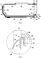
- Figure 3 is a schematic cross-sectional diagram of a drawer assembly according to an embodiment of the present invention.
- Figure 4 is a schematic enlarged diagram of a part D in Figure 3 .
- a drawer assembly 1 according to the embodiments of the present invention includes a sealing barrel 10, a drawer 20 and a tray 30.
- the sealing barrel 10 is configured to be shelved in a refrigerating and freezing device and may be provided with a front-end opening, so that the drawer 20 and the tray 30 are inserted into the sealing barrel 10 via the front end opening in a way of being capable of being pushed and pulled.
- the tray 30 is configured to be inserted into a bottom of the sealing barrel 10 via the front end opening in a way of being capable of being pushed and pulled.
- the drawer 20 is carried on the tray 30 and configured to be inserted into the sealing barrel 10 along with the tray 30 in a way of being capable of being pushed and pulled.
- a closed storage space can be formed inside the drawer 20. It should be noted that the condition that the drawer 20 is in a fully closed state means that the drawer 20 is pushed into the sealing barrel 10 to a maximum extent and cannot be further pushed.
- the tray 30 is provided with a head part 310 located outside the sealing barrel 10 when the drawer 20 is in the fully closed state, a first sealing member 40 is arranged between the head part 310 of the tray 30 and the drawer 20, and the first sealing member 40 includes a body 41 and a deformation blocking sheet 42 extending outward in a bent manner from the body 41 along an arc so as to form airtight sealing between the head part 310 of the tray 30 and the drawer 20.
- the first sealing member 40 is designed between the head part 310 of the tray 30 and the drawer 20, and when the drawer 20 is in the fully closed state, the sealing between the tray 30 and the drawer 20 is realized. Furthermore, in the present application, the first sealing member 40 designed between the tray 30 and the drawer 20 is further specially designed to include a body 41 and a deformation blocking sheet 42 extending outward in a bent manner from the body 41 along an arc, elastic deformation of the first sealing member 40 can be facilitated in terms of both material and shape by means of the deformation blocking sheet 42 in the special shape and the characteristic of generating elastic deformation of the deformation blocking sheet 42, and therefore, in the case of larger manufacturing tolerances for the tray 30 and the drawer 20, it can be ensured that the head part 310 of the tray and the drawer 20 can still realize a good sealing effect.
- the drawer 20 may be provided with a drawer body 210 and a front-end plate 220 arranged on a front side of the drawer body 210.
- a storage space for storing articles is defined in the drawer body 210, and an upper end of the storage space is provided with an opening for a user to take and place articles.
- the front-end plate 220 extends substantially in a vertical direction so as to block the front end opening of the sealing barrel 10 when the drawer 20 is in the fully closed state.
- the front-end plate 220 may be provided with a handle part 221 so as to facilitate the user to push and pull the drawer 20 via the handle part 221.
- the tray 30 may further include a tray bottom plate 320 extending rearward from the head part 310 and a tray rear plate 330 obliquely extending upward from a tail end of the tray bottom plate 320.
- the head part 310 of the tray may be located below the front-end plate 220 and abuts against the front side of the drawer body 20 to support the front-end plate 220, and the tray 30 can be pulled out together when the drawer 20 is pulled outward.
- the tray bottom plate 320 may be located below the drawer body 210 to support the drawer body 210.
- the tray rear plate 330 abuts against a rear side of a rear wall of the drawer body 210, so that when the drawer 20 is pushed into the sealing barrel 10, the tray 30 is pushed into the sealing barrel 10 together.
- the first sealing member 40 is connected to the head part 310 of the tray 30.
- the deformation blocking sheet 42 of the first sealing member 40 extends downward in a suspending manner from front to back from the body 41 of the first sealing member 40 along an arc, and is in elastic extrusion contact with the drawer 20.
- the deformation blocking sheet 42 may be in elastic extrusion contact with a bottom corner of a front end of the drawer 20.
- the tray 30 and the drawer 20 are relatively immobile, that is, the first sealing member 40 between the tray 30 and the drawer 20 will not be frequently switched between elastic deformation and deformation recovery. Therefore, the requirements for generating the elastic deformation of the first sealing member 40 are higher than the requirements for recovering the deformation.
- the deformation blocking sheet 42 of the first sealing member 40 is specially designed to extend downward in a suspending manner from front to back from the body of the first sealing member along an arc, so as to well meet the above requirements.
- the thickness of the deformation blocking sheet 42 gradually decreases from top to bottom, the thinner part is favorable for generating the elastic deformation, and the thicker part can provide certain deformation resistance, so as to increase the acting force between the deformation blocking sheet 42 and the drawer 20, thereby improving the sealing effect between the deformation blocking sheet and the drawer.
- the tray 30 is further provided with a tray bottom plate 320 connected to a rear side of the head part 310.
- the extending tail end of the deformation blocking sheet 42 abuts against the upper surface of the tray bottom plate 320. In this way, the extending tail end of the deformation blocking sheet 42 can be supported to a certain extent, the deformation resistance of the deformation blocking sheet 42 can be appropriately improved, and the reaction required for the same deformation is increased, thereby enhancing the sealing performance between the tray 30 and the drawer 20.
- the deformation blocking sheet 42 of the first sealing member 40 may also extend outward along other arcs, for example, extend upward along the arcs from front to back.
- the drawer assembly 1 further includes a display control assembly 80
- the tray 30 further includes a display cover 340 covering a front side of the head part 310
- the display control assembly 80 is arranged in an accommodating space defined between the display cover 340 and the head part 310.
- the suspending deformation blocking sheet 42 can block moisture in the drawer 20 to the outside of the tray 30 in advance, so as to prevent the moisture from entering the accommodating space via an assembly gap between the tray 30 and the drawer 20 and causing the display control assembly 80 to fail.
- the display control assembly 80 is configured to adjust and display parameters in the drawer 20.
- the display control assembly may be configured to adjust and display temperature, humidity or other environmental parameters in the drawer 20, and may also be configured to display the parameters such as the name and expiration date of the stored food.
- the drawer assembly 1 may further include a wireless power supply generating module, a wireless power supply receiving module, cables, etc., which are arranged in the sealing barrel 10.
- a middle part of the body 41 of the first sealing member 40 is provided with a first slot 411 having a downward notch.
- the head part 310 of the tray 30 is provided with a first flange 311 extending upward, and the first flange 311 is inserted into the first slot 411 so as to form a labyrinth type airtight structure between a gap between the drawer 20 and the tray bottom plate 320 and the accommodating space. If condensed water occurs in the accommodating space where the display control assembly 80 is located, the display control assembly will fail.
- a labyrinth type airtight structure can be formed between the gap between the drawer 20 and the tray bottom plate 320 and the above accommodating space, thereby effectively preventing the moisture flow inside the drawer 20 from entering the accommodating space and causing the display control assembly 80 to fail.
- the deformation blocking sheet 42 of the first sealing member 40 may be in elastic extrusion contact with a front end of a lower part of the drawer body 210.
- the display cover 340 includes a display section 341 and an extending section 342.
- the display section 341 is arranged on the front side of the head part 310 of the tray and located below the front end plate 220.
- the extending section 342 extends rearward from an upper end of the display section 341 and is inserted between the front end plate 220 and the head part 310 of the tray, and the body 41 of the first sealing member 40 is clamped between the extending section 342 of the display cover 340 and the head part 310 of the tray 30.
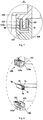
- Figure 5 is a schematic enlarged diagram of a part C in Figure 3 .
- a second sealing member 50 is arranged between the head part 310 of the tray 30 and a front end of a bottom plate 113 of the sealing barrel 10, and the second sealing member 50 includes a body 51 and a deformation blocking sheet 52 extending outward in a bent manner from the body 51 along a broken line, so that when the drawer 20 is in the fully closed state, airtight sealing is formed between the head part of the tray 30 and the bottom plate 113 of the sealing barrel 10.
- the deformation blocking sheet 52 has a bent shape, and therefore, the deformation resistance of the deformation blocking sheet 52 can be appropriately improved, and the reaction required for the same deformation is increased, thereby enhancing the sealing performance between the tray 30 and the front end of the bottom plate 113 of the sealing barrel 10.
- the second sealing member 50 may be connected to the bottom plate 113 of the sealing barrel 10.
- the deformation blocking sheet 52 of the second sealing member 50 obliquely downward extends forward from the body 51 of the second sealing member 50 and then obliquely upward extends forward, so as to be in elastic extrusion contact with the head part 310 of the tray 30 when the drawer 20 is in the fully closed state. Therefore, the section of the deformation blocking sheet 52 that obliquely upward extends forward can be allowed to have a sufficient length to generate sufficient elastic deformation.
- the length of a first section 521 of the deformation blocking sheet 52 that obliquely extends downward is smaller than the length of a second section 522 of the deformation blocking sheet 52 that obliquely extends upward.
- the longer second section 522 extending upward can ensure that the deformation blocking sheet 52 generates sufficient elastic deformation when the drawer 20 is in the fully closed state, and on the other hand, the shorter first section 521 extending downward can provide a certain deformation-resistant acting force, so as to increase the interaction force between the deformation blocking sheet 52 and the bottom plate 113 of the sealing barrel, thereby further enhancing the sealing effect between the tray 30 and the sealing barrel 20.
- the deformation blocking sheet 52 of the second sealing member 50 may also extend outward along other broken lines, for example, first obliquely upward extending forward and then obliquely downward extending forward.
- the front end of the bottom plate 113 of the sealing barrel is provided with a second groove 114 recessed rearward, and the notch of the second groove 114 faces forward.
- the body 51 of the second sealing member 50 includes a limiting part 511 connected to a rear side of the deformation blocking sheet 52 and a connecting part 512 extending rearward from the limiting part 511.
- the connecting part 512 is inserted into the second groove 114 of the bottom plate 113, realizing the installation of the second sealing member 50.
- the limiting part 511 abuts against the front end of the bottom plate 113, realizing the airtight sealing between the second sealing member 50 and the bottom plate 113 of the sealing barrel.
- the connecting part 512 extends rearward from a middle part of the limiting part 511 to enable upper and lower parts of the limiting part 511 to abut against the front end of the bottom plate 113, so that labyrinth type airtight sealing is formed between the second sealing member 50 and the bottom plate 113 of the sealing barrel, enhancing the sealing effect.
- the thickness of the upper part of the limiting part 511 in the front-rear direction is smaller than the thickness of the lower part of the limiting part 511 in the front-rear direction.
- An extending tail end (i.e., a rear end) of the connecting part 512 is provided with anti-drop barbs to prevent the connecting part 512 from detaching from the second groove 114 of the bottom plate 113, thereby improving the installation stability of the second sealing member 50.
- Figure 6 is a schematic enlarged diagram of a part B in Figure 3 .
- a third sealing member 60 is arranged between the front end plate 220 and a front end of a top plate of the sealing barrel 10, and the third sealing member 60 includes a body 61 and a deformation blocking sheet 62 extending outward in a bent manner from the body 61 along a broken line, so that when the drawer 20 in the fully closed state, airtight sealing is formed between the front end plate 220 and the top plate of the sealing barrel 10.
- the deformation blocking sheet 62 has a bent shape, and therefore, the deformation resistance of the deformation blocking sheet 62 can be appropriately improved, and the reaction required for the same deformation is increased, thereby enhancing the sealing performance between the front-end plate 220 and the front end of the top plate of the sealing barrel 10.
- the third sealing member 60 may be connected to a barrel cover 120 of the sealing barrel 10.
- the deformation blocking sheet 62 of the third sealing member 60 obliquely upward extends forward from the body 61 of the third sealing member 60 and then obliquely downward extends forward, so as to be in elastic extrusion contact with the front-end plate 220 when the drawer 20 is in the fully closed state. Therefore, it is possible to avoid the formation of a groove having an upward opening on the third sealing member 60 to accumulate dirt, thereby ensuring that the position of the third sealing member 60 remains clean and tidy for a long time.
- the length of a first section 621 of the deformation blocking sheet 62 that obliquely extends upward is smaller than the length of a second section 622 of the deformation blocking sheet 62 that obliquely extends downward.
- the longer second section 622 extending downward can ensure that the deformation blocking sheet 62 generates sufficient elastic deformation when the drawer 20 is in the fully closed state, and on the other hand, the shorter first section 621 extending upward can provide a certain deformation-resistant acting force, so as to increase the interaction force between the deformation blocking sheet 62 and the front end plate 220, thereby further enhancing the sealing effect between the front end plate 220 and the sealing barrel 20.
- the deformation blocking sheet 62 of the third sealing member 60 may also extend outward along other broken lines, for example, first obliquely downward extending forward and then obliquely upward extending forward.
- the front end of the barrel cover 120 of the sealing barrel 10 is provided with a first groove 122 recessed rearward, and the notch of the first groove 122 faces forward.
- the body 61 of the third sealing member 60 includes a limiting part 611 connected to a rear side of the deformation blocking sheet 62 and a connecting part 612 extending rearward from the limiting part 611.
- the connecting part 612 is inserted into the first groove 122 of the barrel cover 120, realizing the installation of the third sealing member 60.
- the limiting part 611 abuts against the front end of the barrel cover 120, realizing the airtight sealing between the third sealing member 60 and the barrel cover 120.
- the connecting part 612 extends rearward from a middle part of the limiting part 611 to enable upper and lower parts of the limiting part 611 to abut against the front end of the barrel cover 120, so that labyrinth type airtight sealing is formed between the third sealing member 60 and the barrel cover 120, enhancing the sealing effect.
- the thickness of the upper part of the limiting part 611 in the front-rear direction is greater than the thickness of the lower part of the limiting part 611 in the front-rear direction.
- An extending tail end (i.e., a rear end) of the connecting part 612 is provided with anti-drop barbs to prevent the connecting part 612 from detaching from the first groove 122 of the barrel cover 120, thereby improving the installation stability of the third sealing member 60.
- the sealing barrel 10 may include a barrel body 110 provided with a top opening and a barrel cover 120 configured to cover the top opening of the barrel body 110.
- the barrel cover 120 may be provided with a horizontally extending plate part 123 and convex edges 124 extending downward from the two horizontal side edges and the rear side edge of the plate part 123, the plate part 123 of the barrel cover 120 forms a top plate of the sealing barrel 10, and the bottom plate 113 of the sealing barrel 10 is formed on the barrel body 110.
- the barrel body 110 and the barrel cover 120 may be fastened by screw connection, clamping connection or other suitable manners.
- Labyrinth type airtight sealing may be formed between the barrel body 110 and the barrel cover 120 via a sealing component 70 with a U-shaped cross section.
- the designer of the present application breaks through the traditional design thinking and designs the sealing barrel 10 of the drawer assembly 1 into a split type with the barrel body 110 and the barrel cover 120, so that on the basis of simplifying a mold, the deformation of the barrel body 110 and the barrel cover 120 during mold stripping is avoided, the structural stability of the sealing barrel 10 is improved, and the usable space in the sealing barrel 10 is increased.
- the present application further specially designs the sealing component 70 with the U-shaped cross section between the barrel body 110 and the barrel cover 120, so as to form labyrinth type airtight sealing between the barrel body and the barrel cover.
- the sealing component 70 can be easily assembled.
- the outside air enters the closed space in the drawer 20 via the possible gap between the barrel body 110 and the barrel cover 120, it must pass through a labyrinth type path formed by the arrangement of the sealing component 70, the necessary path is greatly extended, and therefore, the sealing effect is better.
- Figure 8 is a schematic exploded cross-sectional diagram of partial structures of a drawer assembly according to an embodiment of the present invention.
- the top of the barrel body 110 is provided with a skirt part 111 extending outward from an outer surface of a circumferential wall of the barrel body 110 and then extending upward in a bent manner.
- the length of the skirt part 111 extending upward in a bent manner can enable a tail end of the skirt part 111 to be flush with the circumferential wall of the barrel body 110.
- a third groove 112 is defined between the skirt part 111 and the circumferential wall of the barrel body 110, a notch of the third groove 112 faces upward, and the sealing component 70 is arranged in the third groove 112.
- the outer side of the skirt part 111 may be provided with a plurality of claws, and edge parts of the convex edges 124 may be provided with a plurality of buckles corresponding to the claws of the skirt part one by one, so that fastening connection between the barrel cover 120 and the barrel body 110 can be realized by means of the clamping connection between the claws and the buckles.
- a second slot 71 with an upward opening is formed in a middle part of the sealing component 70.
- An edge part of the barrel cover 120 configured to be matched with the barrel body 110, is provided with a second flange 121 extending downward, and the second flange 121 is inserted into the second slot 71 of the sealing component 70 from top to bottom so as to form labyrinth type airtight sealing between the interface of the barrel cover 120 and the sealing component 70 and the interface of the sealing component 70 and the barrel body 110, thereby effectively preventing the inside air and outside air of the sealing barrel 10 from communicating via the interface between the barrel cover 120 and the sealing component 70 and the interface between the sealing component 70 and the barrel body 110.
- the second flange 121 is a wedge-shaped body with a thick top and a thin bottom.
- the cross section of the second flange 121 is tapered from top to bottom, that is, the cross section of the second flange 121 is approximately inverted trapezoidal.
- a vertical outer circumferential surface 121a on the outer side and a vertical outer circumferential surface 121b on the inner side of the second flange 121 may both be oblique surfaces extending substantially in a vertical direction, and the two have opposite oblique directions and substantially the same oblique degrees.
- the flange on the barrel cover 120 configured to be inserted into the slot of the sealing component 70, is further specially designed as a wedge-shaped body with a thick top and a thin bottom, thereby improving the smoothness of connection and matching between the barrel cover 120 and the barrel body 110. Furthermore, by means of the thicker top of the second flange, extrusion contact is formed between the second flange 121 and the sealing component 70 as well as between the sealing component 70 and the third groove 112 of the barrel body 110, thereby reducing or even avoiding the possibility of gap formation, and further improving the sealing effect between the barrel body 110 and the barrel cover 120.
- the second slot 71 is defined by an inner vertical inner circumferential surface 72 on the inner side, an outer vertical inner circumferential surface 73 on the outer side and an inner bottom surface 74 of the sealing component 70.
- a minimum vertical distance between the vertical outer circumferential surface 121a on the outer side of the second flange 121 and an inner surface 111a of the skirt part 111 is slightly smaller than a vertical distance between the outer vertical inner circumferential surface 73 defining the second slot 71 and the inner surface 111a of the skirt part 111 when the sealing component 70 is in a natural state.
- the condition that the sealing component 70 is in a natural state means that the sealing component 70 is not subjected to the acting force of external extrusion or stretching, that is, a state without any deformation.
- the sealing component 70 can be outwardly supported to a certain extent, causing it to generate deformation and be in close contact with the circumferential wall of the barrel body 110 and the skirt part 111, and improving the sealing effect between the barrel body 110 and the sealing component 70 as well as between the barrel cover 120 and the sealing component 70.
- the sealing component 70 may be an elastic sealing strip with a U-shaped cross section.
- the elastic sealing strip may include three strip-shaped sealing sections which are respectively located on the two horizontal sides and the rear side of the sealing barrel 10.
- the strip-shaped sealing section on the rear side of the sealing barrel 10 may be connected with the two strip-shaped sealing sections on the two horizontal sides of the sealing barrel 10 in suitable manners, or the three strip-shaped sealing sections are integrally formed, or the three strip-shaped sealing sections are independent of each other.
- the drawer assembly 1 of the present invention further includes a modified atmosphere preservation module 90, and the modified atmosphere preservation module 90 may be arranged on the inner side of the barrel cover 120. Due to the arrangement of the modified atmosphere preservation module 90, the inside of the drawer assembly 1 needs to be sealed with higher precision, and the modified atmosphere preservation module 90 needs to be repaired or replaced. In this way, in the present application, the drawer assembly 1 is split into multiple parts, and a sealing member is arranged between every two parts, which not only facilitates the manufacture, repair or replacement of each part, but also ensures that good sealing can be formed at the interface between every two parts, so that sealing with a better effect and a higher level is formed inside the drawer.
- the designer of the present application has realized through deep analysis that different parts of the drawer assembly 1 are different due to their positions, their own structures and other structures that match them, and therefore, the structural type of the sealing member used between different parts will have a greater impact on the sealing performance of the entire drawer assembly.
- each of the first sealing member 40 arranged between the head part 310 of the tray 30 and the drawer 20, the second sealing member 50 arranged between the head part 310 of the tray 30 and the front end of the bottom plate 113 of the sealing barrel 10, and the third sealing member 60 arranged between the front end plate 220 and the front end of the barrel cover 120 of the sealing barrel 10 is further designed to be provided with the body and the deformation blocking sheet extending outward in a bent manner from the body along the arc or the broken line.
- Elastic deformation of the sealing member can be facilitated in terms of both material and shape by means of the deformation blocking sheet in the special shape and the characteristic of generating elastic deformation of the deformation blocking sheet, and therefore, in the case of larger manufacturing tolerances for the tray, the sealing barrel, the front end plate and the drawer, it can be ensured that the interface can still realize a good sealing effect.
- the present invention further provides a refrigerating and freezing device.
- Figure 9 is a schematic structural diagram of a refrigerating and freezing device according to an embodiment of the present invention.
- the refrigerating and freezing device 2 of the present invention includes a box body 3 and the drawer assembly 1 described in any one of the above embodiments. At least one storage compartment is defined in the box body 3, and the drawer assembly 1 is detachably arranged in one of the storage compartments so as to provide a closed storage space for the refrigerating and freezing device 2.
Landscapes
- Engineering & Computer Science (AREA)
- General Engineering & Computer Science (AREA)
- Mechanical Engineering (AREA)
- Chemical & Material Sciences (AREA)
- Combustion & Propulsion (AREA)
- Physics & Mathematics (AREA)
- Thermal Sciences (AREA)
- Refrigerator Housings (AREA)
- Cold Air Circulating Systems And Constructional Details In Refrigerators (AREA)
- Packages (AREA)
Applications Claiming Priority (2)
| Application Number | Priority Date | Filing Date | Title |
|---|---|---|---|
| CN201810404431.2A CN108444197B (zh) | 2018-04-28 | 2018-04-28 | 冷藏冷冻装置及其抽屉组件 |
| PCT/CN2019/077040 WO2019205817A1 (zh) | 2018-04-28 | 2019-03-05 | 冷藏冷冻装置及其抽屉组件 |
Publications (3)
| Publication Number | Publication Date |
|---|---|
| EP3789709A1 true EP3789709A1 (de) | 2021-03-10 |
| EP3789709A4 EP3789709A4 (de) | 2021-06-30 |
| EP3789709B1 EP3789709B1 (de) | 2022-01-05 |
Family
ID=63202549
Family Applications (1)
| Application Number | Title | Priority Date | Filing Date |
|---|---|---|---|
| EP19794076.0A Active EP3789709B1 (de) | 2018-04-28 | 2019-03-05 | Kühl- und gefriervorrichtung und eine schubladenanordnung dafür |
Country Status (3)
| Country | Link |
|---|---|
| EP (1) | EP3789709B1 (de) |
| CN (2) | CN120008292A (de) |
| WO (1) | WO2019205817A1 (de) |
Families Citing this family (4)
| Publication number | Priority date | Publication date | Assignee | Title |
|---|---|---|---|---|
| CN120008292A (zh) * | 2018-04-28 | 2025-05-16 | 海尔智家股份有限公司 | 冷藏冷冻装置及其抽屉组件 |
| CN108397962B (zh) * | 2018-04-28 | 2025-02-25 | 海尔智家股份有限公司 | 冷藏冷冻装置及其抽屉组件 |
| CN111692824B (zh) * | 2019-03-12 | 2026-03-06 | 青岛海尔电冰箱有限公司 | 冰箱 |
| CN116373214B (zh) * | 2022-12-30 | 2026-01-09 | 江苏亿豪塑业股份有限公司 | 一种聚四氟乙烯管材加工成型装置 |
Family Cites Families (22)
| Publication number | Priority date | Publication date | Assignee | Title |
|---|---|---|---|---|
| ZA994076B (en) * | 1999-06-21 | 2000-02-23 | Marc Chadwick | Refrigerator storage tray. |
| GB2398355B (en) * | 2003-09-05 | 2004-12-29 | Applied Design & Eng Ltd | Improvements in or relating to seals |
| MX2009003907A (es) * | 2006-11-28 | 2009-05-28 | Fritz Hakemann | Cierre de mueble. |
| US20100083687A1 (en) * | 2007-04-17 | 2010-04-08 | Mitsubishi Electric Corporation | Refrigerator and frozen food preservation method |
| JP4961295B2 (ja) * | 2007-08-02 | 2012-06-27 | 日立アプライアンス株式会社 | 冷蔵庫 |
| CN102261794B (zh) * | 2010-05-28 | 2015-08-26 | 博西华家用电器有限公司 | 家用电器 |
| CN202066291U (zh) * | 2011-05-16 | 2011-12-07 | 合肥美的荣事达电冰箱有限公司 | 抽屉式冰箱供电组件及具有该供电组件的冰箱 |
| CN202158713U (zh) * | 2011-07-06 | 2012-03-07 | 海尔集团公司 | 一种冰箱密封结构 |
| KR101327914B1 (ko) * | 2011-07-18 | 2013-11-13 | 위니아만도 주식회사 | 냉장고의 밀폐룸 |
| DE102011087785A1 (de) * | 2011-12-06 | 2013-06-06 | BSH Bosch und Siemens Hausgeräte GmbH | Haushaltskältegerät mit einem Fachboden |
| CN102901317B (zh) * | 2012-11-09 | 2014-09-24 | 海尔集团公司 | 密封存储装置 |
| CN202993735U (zh) * | 2012-11-23 | 2013-06-12 | 海尔集团公司 | 一种冰箱托盘以及包括该托盘的冰箱 |
| US9476634B2 (en) * | 2013-03-25 | 2016-10-25 | Lg Electronics Inc. | Refrigerator |
| CN103277970B (zh) * | 2013-04-28 | 2015-09-02 | 海尔集团公司 | 抽屉托架以及具有该抽屉托架的抽屉组件 |
| DE102013225541A1 (de) * | 2013-12-11 | 2015-06-11 | BSH Hausgeräte GmbH | Haushaltskältegerät mit einer feuchtigkeitsdicht abschließenden Kühlgutschublade |
| CN104567196B (zh) * | 2015-01-04 | 2017-01-04 | 青岛海尔股份有限公司 | 冰箱 |
| CN104949454A (zh) * | 2015-06-30 | 2015-09-30 | 合肥美的电冰箱有限公司 | 抽屉及包括该抽屉的冰箱冷冻室 |
| CN106595178B (zh) * | 2016-11-11 | 2019-05-03 | 青岛海尔股份有限公司 | 储物装置和冰箱 |
| CN206959445U (zh) * | 2017-05-11 | 2018-02-02 | 青岛海尔股份有限公司 | 用于冰箱的托盘抽屉组件及冰箱 |
| CN208312819U (zh) * | 2018-04-28 | 2019-01-01 | 青岛海尔股份有限公司 | 冷藏冷冻装置及其抽屉组件 |
| CN108397962B (zh) * | 2018-04-28 | 2025-02-25 | 海尔智家股份有限公司 | 冷藏冷冻装置及其抽屉组件 |
| CN120008292A (zh) * | 2018-04-28 | 2025-05-16 | 海尔智家股份有限公司 | 冷藏冷冻装置及其抽屉组件 |
-
2018
- 2018-04-28 CN CN202510123427.9A patent/CN120008292A/zh active Pending
- 2018-04-28 CN CN201810404431.2A patent/CN108444197B/zh active Active
-
2019
- 2019-03-05 EP EP19794076.0A patent/EP3789709B1/de active Active
- 2019-03-05 WO PCT/CN2019/077040 patent/WO2019205817A1/zh not_active Ceased
Also Published As
| Publication number | Publication date |
|---|---|
| EP3789709A4 (de) | 2021-06-30 |
| CN120008292A (zh) | 2025-05-16 |
| CN108444197B (zh) | 2025-02-25 |
| CN108444197A (zh) | 2018-08-24 |
| EP3789709B1 (de) | 2022-01-05 |
| WO2019205817A1 (zh) | 2019-10-31 |
Similar Documents
| Publication | Publication Date | Title |
|---|---|---|
| EP3789708B1 (de) | Kühl- und gefriervorrichtung und schubladenanordnung dafür | |
| EP3789709B1 (de) | Kühl- und gefriervorrichtung und eine schubladenanordnung dafür | |
| US8215731B2 (en) | Handle assembly for a domestic appliance | |
| US10345029B2 (en) | Refrigerator | |
| US10288342B2 (en) | Refrigerator door with a handle groove | |
| US10113788B2 (en) | Refrigerator drawer and refrigerator | |
| US10215473B2 (en) | Refrigerator | |
| KR20180136533A (ko) | 도어실 및 이를 구비하는 냉동 용기 | |
| US10151524B2 (en) | Refrigerator having a door | |
| CN103443568B (zh) | 制冷器具门 | |
| KR101201511B1 (ko) | 아웃도어의 디스플레이유닛 장착장치 | |
| US20110080077A1 (en) | Storing Apparatus for Use with Tool Cart | |
| CN208312819U (zh) | 冷藏冷冻装置及其抽屉组件 | |
| CN208817842U (zh) | 冷藏冷冻装置及其抽屉组件 | |
| CN208312864U (zh) | 冷藏冷冻装置及其抽屉组件 | |
| CN208312818U (zh) | 冷藏冷冻装置及其抽屉组件 | |
| CN104029905B (zh) | 保鲜盒 | |
| US20160238264A1 (en) | Dehumidifier | |
| CN217876699U (zh) | 定位件及可应用该定位件的冰箱 | |
| EP2975346A1 (de) | Kühlschrank | |
| CN208312865U (zh) | 冷藏冷冻装置及其抽屉组件 | |
| KR20120049585A (ko) | 냉장고 디스플레이 탈착 구조 | |
| CN211451502U (zh) | 冰箱及用于冰箱的搁架装置 | |
| KR20180068628A (ko) | 냉장고 디스플레이 조립 구조 | |
| CN204923665U (zh) | 冰箱 |
Legal Events
| Date | Code | Title | Description |
|---|---|---|---|
| STAA | Information on the status of an ep patent application or granted ep patent |
Free format text: STATUS: THE INTERNATIONAL PUBLICATION HAS BEEN MADE |
|
| PUAI | Public reference made under article 153(3) epc to a published international application that has entered the european phase |
Free format text: ORIGINAL CODE: 0009012 |
|
| STAA | Information on the status of an ep patent application or granted ep patent |
Free format text: STATUS: REQUEST FOR EXAMINATION WAS MADE |
|
| 17P | Request for examination filed |
Effective date: 20201130 |
|
| AK | Designated contracting states |
Kind code of ref document: A1 Designated state(s): AL AT BE BG CH CY CZ DE DK EE ES FI FR GB GR HR HU IE IS IT LI LT LU LV MC MK MT NL NO PL PT RO RS SE SI SK SM TR |
|
| AX | Request for extension of the european patent |
Extension state: BA ME |
|
| A4 | Supplementary search report drawn up and despatched |
Effective date: 20210531 |
|
| RIC1 | Information provided on ipc code assigned before grant |
Ipc: F25D 25/02 20060101ALI20210525BHEP Ipc: F25D 23/08 20060101ALI20210525BHEP Ipc: A47B 88/963 20170101ALI20210525BHEP Ipc: A47B 88/75 20170101AFI20210525BHEP |
|
| DAV | Request for validation of the european patent (deleted) | ||
| DAX | Request for extension of the european patent (deleted) | ||
| REG | Reference to a national code |
Ref country code: DE Ref legal event code: R079 Ref document number: 602019010740 Country of ref document: DE Free format text: PREVIOUS MAIN CLASS: F25D0025020000 Ipc: A47B0088963000 |
|
| GRAP | Despatch of communication of intention to grant a patent |
Free format text: ORIGINAL CODE: EPIDOSNIGR1 |
|
| STAA | Information on the status of an ep patent application or granted ep patent |
Free format text: STATUS: GRANT OF PATENT IS INTENDED |
|
| RIC1 | Information provided on ipc code assigned before grant |
Ipc: F25D 25/02 20060101ALI20210809BHEP Ipc: F25D 23/08 20060101ALI20210809BHEP Ipc: A47B 88/963 20170101AFI20210809BHEP |
|
| INTG | Intention to grant announced |
Effective date: 20210827 |
|
| GRAS | Grant fee paid |
Free format text: ORIGINAL CODE: EPIDOSNIGR3 |
|
| GRAA | (expected) grant |
Free format text: ORIGINAL CODE: 0009210 |
|
| STAA | Information on the status of an ep patent application or granted ep patent |
Free format text: STATUS: THE PATENT HAS BEEN GRANTED |
|
| AK | Designated contracting states |
Kind code of ref document: B1 Designated state(s): AL AT BE BG CH CY CZ DE DK EE ES FI FR GB GR HR HU IE IS IT LI LT LU LV MC MK MT NL NO PL PT RO RS SE SI SK SM TR |
|
| REG | Reference to a national code |
Ref country code: GB Ref legal event code: FG4D |
|
| REG | Reference to a national code |
Ref country code: CH Ref legal event code: EP |
|
| REG | Reference to a national code |
Ref country code: AT Ref legal event code: REF Ref document number: 1459758 Country of ref document: AT Kind code of ref document: T Effective date: 20220115 |
|
| REG | Reference to a national code |
Ref country code: DE Ref legal event code: R096 Ref document number: 602019010740 Country of ref document: DE |
|
| REG | Reference to a national code |
Ref country code: IE Ref legal event code: FG4D |
|
| REG | Reference to a national code |
Ref country code: LT Ref legal event code: MG9D |
|
| REG | Reference to a national code |
Ref country code: NL Ref legal event code: MP Effective date: 20220105 |
|
| REG | Reference to a national code |
Ref country code: AT Ref legal event code: MK05 Ref document number: 1459758 Country of ref document: AT Kind code of ref document: T Effective date: 20220105 |
|
| PG25 | Lapsed in a contracting state [announced via postgrant information from national office to epo] |
Ref country code: NL Free format text: LAPSE BECAUSE OF FAILURE TO SUBMIT A TRANSLATION OF THE DESCRIPTION OR TO PAY THE FEE WITHIN THE PRESCRIBED TIME-LIMIT Effective date: 20220105 |
|
| PG25 | Lapsed in a contracting state [announced via postgrant information from national office to epo] |
Ref country code: SE Free format text: LAPSE BECAUSE OF FAILURE TO SUBMIT A TRANSLATION OF THE DESCRIPTION OR TO PAY THE FEE WITHIN THE PRESCRIBED TIME-LIMIT Effective date: 20220105 Ref country code: RS Free format text: LAPSE BECAUSE OF FAILURE TO SUBMIT A TRANSLATION OF THE DESCRIPTION OR TO PAY THE FEE WITHIN THE PRESCRIBED TIME-LIMIT Effective date: 20220105 Ref country code: PT Free format text: LAPSE BECAUSE OF FAILURE TO SUBMIT A TRANSLATION OF THE DESCRIPTION OR TO PAY THE FEE WITHIN THE PRESCRIBED TIME-LIMIT Effective date: 20220505 Ref country code: NO Free format text: LAPSE BECAUSE OF FAILURE TO SUBMIT A TRANSLATION OF THE DESCRIPTION OR TO PAY THE FEE WITHIN THE PRESCRIBED TIME-LIMIT Effective date: 20220405 Ref country code: LT Free format text: LAPSE BECAUSE OF FAILURE TO SUBMIT A TRANSLATION OF THE DESCRIPTION OR TO PAY THE FEE WITHIN THE PRESCRIBED TIME-LIMIT Effective date: 20220105 Ref country code: HR Free format text: LAPSE BECAUSE OF FAILURE TO SUBMIT A TRANSLATION OF THE DESCRIPTION OR TO PAY THE FEE WITHIN THE PRESCRIBED TIME-LIMIT Effective date: 20220105 Ref country code: ES Free format text: LAPSE BECAUSE OF FAILURE TO SUBMIT A TRANSLATION OF THE DESCRIPTION OR TO PAY THE FEE WITHIN THE PRESCRIBED TIME-LIMIT Effective date: 20220105 Ref country code: BG Free format text: LAPSE BECAUSE OF FAILURE TO SUBMIT A TRANSLATION OF THE DESCRIPTION OR TO PAY THE FEE WITHIN THE PRESCRIBED TIME-LIMIT Effective date: 20220405 |
|
| PG25 | Lapsed in a contracting state [announced via postgrant information from national office to epo] |
Ref country code: PL Free format text: LAPSE BECAUSE OF FAILURE TO SUBMIT A TRANSLATION OF THE DESCRIPTION OR TO PAY THE FEE WITHIN THE PRESCRIBED TIME-LIMIT Effective date: 20220105 Ref country code: LV Free format text: LAPSE BECAUSE OF FAILURE TO SUBMIT A TRANSLATION OF THE DESCRIPTION OR TO PAY THE FEE WITHIN THE PRESCRIBED TIME-LIMIT Effective date: 20220105 Ref country code: GR Free format text: LAPSE BECAUSE OF FAILURE TO SUBMIT A TRANSLATION OF THE DESCRIPTION OR TO PAY THE FEE WITHIN THE PRESCRIBED TIME-LIMIT Effective date: 20220406 Ref country code: FI Free format text: LAPSE BECAUSE OF FAILURE TO SUBMIT A TRANSLATION OF THE DESCRIPTION OR TO PAY THE FEE WITHIN THE PRESCRIBED TIME-LIMIT Effective date: 20220105 Ref country code: AT Free format text: LAPSE BECAUSE OF FAILURE TO SUBMIT A TRANSLATION OF THE DESCRIPTION OR TO PAY THE FEE WITHIN THE PRESCRIBED TIME-LIMIT Effective date: 20220105 |
|
| PG25 | Lapsed in a contracting state [announced via postgrant information from national office to epo] |
Ref country code: IS Free format text: LAPSE BECAUSE OF FAILURE TO SUBMIT A TRANSLATION OF THE DESCRIPTION OR TO PAY THE FEE WITHIN THE PRESCRIBED TIME-LIMIT Effective date: 20220505 |
|
| REG | Reference to a national code |
Ref country code: DE Ref legal event code: R119 Ref document number: 602019010740 Country of ref document: DE |
|
| PG25 | Lapsed in a contracting state [announced via postgrant information from national office to epo] |
Ref country code: SM Free format text: LAPSE BECAUSE OF FAILURE TO SUBMIT A TRANSLATION OF THE DESCRIPTION OR TO PAY THE FEE WITHIN THE PRESCRIBED TIME-LIMIT Effective date: 20220105 Ref country code: SK Free format text: LAPSE BECAUSE OF FAILURE TO SUBMIT A TRANSLATION OF THE DESCRIPTION OR TO PAY THE FEE WITHIN THE PRESCRIBED TIME-LIMIT Effective date: 20220105 Ref country code: RO Free format text: LAPSE BECAUSE OF FAILURE TO SUBMIT A TRANSLATION OF THE DESCRIPTION OR TO PAY THE FEE WITHIN THE PRESCRIBED TIME-LIMIT Effective date: 20220105 Ref country code: MC Free format text: LAPSE BECAUSE OF FAILURE TO SUBMIT A TRANSLATION OF THE DESCRIPTION OR TO PAY THE FEE WITHIN THE PRESCRIBED TIME-LIMIT Effective date: 20220105 Ref country code: EE Free format text: LAPSE BECAUSE OF FAILURE TO SUBMIT A TRANSLATION OF THE DESCRIPTION OR TO PAY THE FEE WITHIN THE PRESCRIBED TIME-LIMIT Effective date: 20220105 Ref country code: DK Free format text: LAPSE BECAUSE OF FAILURE TO SUBMIT A TRANSLATION OF THE DESCRIPTION OR TO PAY THE FEE WITHIN THE PRESCRIBED TIME-LIMIT Effective date: 20220105 Ref country code: CZ Free format text: LAPSE BECAUSE OF FAILURE TO SUBMIT A TRANSLATION OF THE DESCRIPTION OR TO PAY THE FEE WITHIN THE PRESCRIBED TIME-LIMIT Effective date: 20220105 |
|
| REG | Reference to a national code |
Ref country code: CH Ref legal event code: PL |
|
| PLBE | No opposition filed within time limit |
Free format text: ORIGINAL CODE: 0009261 |
|
| STAA | Information on the status of an ep patent application or granted ep patent |
Free format text: STATUS: NO OPPOSITION FILED WITHIN TIME LIMIT |
|
| PG25 | Lapsed in a contracting state [announced via postgrant information from national office to epo] |
Ref country code: AL Free format text: LAPSE BECAUSE OF FAILURE TO SUBMIT A TRANSLATION OF THE DESCRIPTION OR TO PAY THE FEE WITHIN THE PRESCRIBED TIME-LIMIT Effective date: 20220105 |
|
| REG | Reference to a national code |
Ref country code: BE Ref legal event code: MM Effective date: 20220331 |
|
| 26N | No opposition filed |
Effective date: 20221006 |
|
| PG25 | Lapsed in a contracting state [announced via postgrant information from national office to epo] |
Ref country code: LU Free format text: LAPSE BECAUSE OF NON-PAYMENT OF DUE FEES Effective date: 20220305 Ref country code: LI Free format text: LAPSE BECAUSE OF NON-PAYMENT OF DUE FEES Effective date: 20220331 Ref country code: IE Free format text: LAPSE BECAUSE OF NON-PAYMENT OF DUE FEES Effective date: 20220305 Ref country code: DE Free format text: LAPSE BECAUSE OF NON-PAYMENT OF DUE FEES Effective date: 20221001 Ref country code: CH Free format text: LAPSE BECAUSE OF NON-PAYMENT OF DUE FEES Effective date: 20220331 |
|
| PG25 | Lapsed in a contracting state [announced via postgrant information from national office to epo] |
Ref country code: SI Free format text: LAPSE BECAUSE OF FAILURE TO SUBMIT A TRANSLATION OF THE DESCRIPTION OR TO PAY THE FEE WITHIN THE PRESCRIBED TIME-LIMIT Effective date: 20220105 Ref country code: BE Free format text: LAPSE BECAUSE OF NON-PAYMENT OF DUE FEES Effective date: 20220331 |
|
| PG25 | Lapsed in a contracting state [announced via postgrant information from national office to epo] |
Ref country code: IT Free format text: LAPSE BECAUSE OF FAILURE TO SUBMIT A TRANSLATION OF THE DESCRIPTION OR TO PAY THE FEE WITHIN THE PRESCRIBED TIME-LIMIT Effective date: 20220105 |
|
| PG25 | Lapsed in a contracting state [announced via postgrant information from national office to epo] |
Ref country code: MK Free format text: LAPSE BECAUSE OF FAILURE TO SUBMIT A TRANSLATION OF THE DESCRIPTION OR TO PAY THE FEE WITHIN THE PRESCRIBED TIME-LIMIT Effective date: 20220105 Ref country code: CY Free format text: LAPSE BECAUSE OF FAILURE TO SUBMIT A TRANSLATION OF THE DESCRIPTION OR TO PAY THE FEE WITHIN THE PRESCRIBED TIME-LIMIT Effective date: 20220105 |
|
| PG25 | Lapsed in a contracting state [announced via postgrant information from national office to epo] |
Ref country code: HU Free format text: LAPSE BECAUSE OF FAILURE TO SUBMIT A TRANSLATION OF THE DESCRIPTION OR TO PAY THE FEE WITHIN THE PRESCRIBED TIME-LIMIT; INVALID AB INITIO Effective date: 20190305 |
|
| PG25 | Lapsed in a contracting state [announced via postgrant information from national office to epo] |
Ref country code: MT Free format text: LAPSE BECAUSE OF FAILURE TO SUBMIT A TRANSLATION OF THE DESCRIPTION OR TO PAY THE FEE WITHIN THE PRESCRIBED TIME-LIMIT Effective date: 20220105 |
|
| PG25 | Lapsed in a contracting state [announced via postgrant information from national office to epo] |
Ref country code: TR Free format text: LAPSE BECAUSE OF FAILURE TO SUBMIT A TRANSLATION OF THE DESCRIPTION OR TO PAY THE FEE WITHIN THE PRESCRIBED TIME-LIMIT Effective date: 20220105 |
|
| PGFP | Annual fee paid to national office [announced via postgrant information from national office to epo] |
Ref country code: GB Payment date: 20260323 Year of fee payment: 8 |
|
| PGFP | Annual fee paid to national office [announced via postgrant information from national office to epo] |
Ref country code: FR Payment date: 20260330 Year of fee payment: 8 |