EP3789660A1 - Multi-segment vehicle turning light lamp - Google Patents
Multi-segment vehicle turning light lamp Download PDFInfo
- Publication number
- EP3789660A1 EP3789660A1 EP19195625.9A EP19195625A EP3789660A1 EP 3789660 A1 EP3789660 A1 EP 3789660A1 EP 19195625 A EP19195625 A EP 19195625A EP 3789660 A1 EP3789660 A1 EP 3789660A1
- Authority
- EP
- European Patent Office
- Prior art keywords
- light
- lamp
- substrate
- lens
- emitting elements
- Prior art date
- Legal status (The legal status is an assumption and is not a legal conclusion. Google has not performed a legal analysis and makes no representation as to the accuracy of the status listed.)
- Granted
Links
- 239000000758 substrate Substances 0.000 claims abstract description 34
- 238000005192 partition Methods 0.000 claims abstract description 18
- 230000003287 optical effect Effects 0.000 claims description 11
- 241000258971 Brachiopoda Species 0.000 claims description 10
- 238000005286 illumination Methods 0.000 description 7
- 230000003044 adaptive effect Effects 0.000 description 1
- 238000010276 construction Methods 0.000 description 1
- 230000000694 effects Effects 0.000 description 1
- 238000005516 engineering process Methods 0.000 description 1
- 238000000605 extraction Methods 0.000 description 1
- 229910052736 halogen Inorganic materials 0.000 description 1
- 150000002367 halogens Chemical class 0.000 description 1
- 230000000007 visual effect Effects 0.000 description 1
Images


Classifications
-
- F—MECHANICAL ENGINEERING; LIGHTING; HEATING; WEAPONS; BLASTING
- F21—LIGHTING
- F21S—NON-PORTABLE LIGHTING DEVICES; SYSTEMS THEREOF; VEHICLE LIGHTING DEVICES SPECIALLY ADAPTED FOR VEHICLE EXTERIORS
- F21S41/00—Illuminating devices specially adapted for vehicle exteriors, e.g. headlamps
- F21S41/10—Illuminating devices specially adapted for vehicle exteriors, e.g. headlamps characterised by the light source
- F21S41/14—Illuminating devices specially adapted for vehicle exteriors, e.g. headlamps characterised by the light source characterised by the type of light source
- F21S41/141—Light emitting diodes [LED]
- F21S41/143—Light emitting diodes [LED] the main emission direction of the LED being parallel to the optical axis of the illuminating device
-
- B—PERFORMING OPERATIONS; TRANSPORTING
- B60—VEHICLES IN GENERAL
- B60Q—ARRANGEMENT OF SIGNALLING OR LIGHTING DEVICES, THE MOUNTING OR SUPPORTING THEREOF OR CIRCUITS THEREFOR, FOR VEHICLES IN GENERAL
- B60Q1/00—Arrangement of optical signalling or lighting devices, the mounting or supporting thereof or circuits therefor
- B60Q1/02—Arrangement of optical signalling or lighting devices, the mounting or supporting thereof or circuits therefor the devices being primarily intended to illuminate the way ahead or to illuminate other areas of way or environments
- B60Q1/04—Arrangement of optical signalling or lighting devices, the mounting or supporting thereof or circuits therefor the devices being primarily intended to illuminate the way ahead or to illuminate other areas of way or environments the devices being headlights
- B60Q1/06—Arrangement of optical signalling or lighting devices, the mounting or supporting thereof or circuits therefor the devices being primarily intended to illuminate the way ahead or to illuminate other areas of way or environments the devices being headlights adjustable, e.g. remotely-controlled from inside vehicle
- B60Q1/08—Arrangement of optical signalling or lighting devices, the mounting or supporting thereof or circuits therefor the devices being primarily intended to illuminate the way ahead or to illuminate other areas of way or environments the devices being headlights adjustable, e.g. remotely-controlled from inside vehicle automatically
- B60Q1/12—Arrangement of optical signalling or lighting devices, the mounting or supporting thereof or circuits therefor the devices being primarily intended to illuminate the way ahead or to illuminate other areas of way or environments the devices being headlights adjustable, e.g. remotely-controlled from inside vehicle automatically due to steering position
-
- F—MECHANICAL ENGINEERING; LIGHTING; HEATING; WEAPONS; BLASTING
- F21—LIGHTING
- F21S—NON-PORTABLE LIGHTING DEVICES; SYSTEMS THEREOF; VEHICLE LIGHTING DEVICES SPECIALLY ADAPTED FOR VEHICLE EXTERIORS
- F21S41/00—Illuminating devices specially adapted for vehicle exteriors, e.g. headlamps
- F21S41/20—Illuminating devices specially adapted for vehicle exteriors, e.g. headlamps characterised by refractors, transparent cover plates, light guides or filters
- F21S41/25—Projection lenses
- F21S41/26—Elongated lenses
-
- F—MECHANICAL ENGINEERING; LIGHTING; HEATING; WEAPONS; BLASTING
- F21—LIGHTING
- F21S—NON-PORTABLE LIGHTING DEVICES; SYSTEMS THEREOF; VEHICLE LIGHTING DEVICES SPECIALLY ADAPTED FOR VEHICLE EXTERIORS
- F21S41/00—Illuminating devices specially adapted for vehicle exteriors, e.g. headlamps
- F21S41/20—Illuminating devices specially adapted for vehicle exteriors, e.g. headlamps characterised by refractors, transparent cover plates, light guides or filters
- F21S41/28—Cover glass
-
- F—MECHANICAL ENGINEERING; LIGHTING; HEATING; WEAPONS; BLASTING
- F21—LIGHTING
- F21S—NON-PORTABLE LIGHTING DEVICES; SYSTEMS THEREOF; VEHICLE LIGHTING DEVICES SPECIALLY ADAPTED FOR VEHICLE EXTERIORS
- F21S41/00—Illuminating devices specially adapted for vehicle exteriors, e.g. headlamps
- F21S41/30—Illuminating devices specially adapted for vehicle exteriors, e.g. headlamps characterised by reflectors
- F21S41/32—Optical layout thereof
- F21S41/321—Optical layout thereof the reflector being a surface of revolution or a planar surface, e.g. truncated
-
- F—MECHANICAL ENGINEERING; LIGHTING; HEATING; WEAPONS; BLASTING
- F21—LIGHTING
- F21S—NON-PORTABLE LIGHTING DEVICES; SYSTEMS THEREOF; VEHICLE LIGHTING DEVICES SPECIALLY ADAPTED FOR VEHICLE EXTERIORS
- F21S41/00—Illuminating devices specially adapted for vehicle exteriors, e.g. headlamps
- F21S41/60—Illuminating devices specially adapted for vehicle exteriors, e.g. headlamps characterised by a variable light distribution
- F21S41/65—Illuminating devices specially adapted for vehicle exteriors, e.g. headlamps characterised by a variable light distribution by acting on light sources
- F21S41/663—Illuminating devices specially adapted for vehicle exteriors, e.g. headlamps characterised by a variable light distribution by acting on light sources by switching light sources
-
- F—MECHANICAL ENGINEERING; LIGHTING; HEATING; WEAPONS; BLASTING
- F21—LIGHTING
- F21W—INDEXING SCHEME ASSOCIATED WITH SUBCLASSES F21K, F21L, F21S and F21V, RELATING TO USES OR APPLICATIONS OF LIGHTING DEVICES OR SYSTEMS
- F21W2102/00—Exterior vehicle lighting devices for illuminating purposes
- F21W2102/10—Arrangement or contour of the emitted light
- F21W2102/17—Arrangement or contour of the emitted light for regions other than high beam or low beam
- F21W2102/19—Arrangement or contour of the emitted light for regions other than high beam or low beam for curves
Definitions
- the disclosure relates to a light lamp for a vehicle, more particularly to a multi-segment vehicle turning light lamp which is configured for multi-segmented illuminatinon and can be used in vehicles with three or more wheels.
- a conventional turning light lamp is mounted on the outer side of a headlight 11 which acts as a main illumination source of a vehicle and which has an optical axis extending in a front-rear direction.
- the conventional turning light lamp includes a curved reflector 12, and a halogen bulb 13 disposed with respect to the reflector 12.
- Such a turning light lamp can provide illumination in addition to the illumination provided by the headlight 11 while the vehicle is turning, such that the vehicle turning safety can be enhanced.
- the above-mentioned turning light lamp is bulky and provides only single-segment lighting.
- the object of the disclosure is to provide a multi-segment vehicle turning light lamp to overcome at least one disadvantage of the prior art.
- the multi-segment vehicle turning light lamp includes a lamp housing assembly and a lighting assembly.
- the lamp housing assembly includes a substrate having a plane surface, a lens disposed in front of the substrate and having a concave inner surface that faces the substrate, and a light divider arrangement disposed between the substrate and the lens.
- the light divider arrangement includes a plurality of partitions that are angularly arranged with respect to a center of curvature of the concave inner surface of the lens and that extend radially to the lens.
- the plurality of partitions, the substrate and the lens cooperate to define a plurality of light-exit channels.
- the lighting assembly includes a plurality of light-emitting elements disposed on the plane surface of the substrate. Each of the light-emitting elements is disposed for emitting light through a respective one of the light-exit channels.
- an embodiment of the multi-segment turning light lamp according to the present disclosure can be mounted by the side of a headlight (not shown) of a vehicle.
- the headlight emits light along an optical axis extending in a front-rear direction (D1).
- the multi-segment turning light lamp includes a lamp housing assembly 2 and a lighting assembly 3.
- the lamp housing assembly 2 includes a substantially U-shaped lamp holder 21, a substrate 22 fixed on the lamp holder 21, a lens 23 disposed in front of and spaced from the substrate 22, a light divider arrangement 24 provided between the substrate 22 and the lens 23, and upper and lower lamp shells 26 disposed respectively on upper and lower sides of the substrate 22, the lens 23 and the light divider arrangement 24.
- the substrate 22 has a plane surface. A direction (D2) normal to the plane surface of the substrate 22 is inclined to the front-rear direction (D1).
- the lamp holder 21 includes a base portion 211 which is perpendicular to the direction (D2) which is normal to the plane surface of the substrate 22, and a pair of side wing portions 212 extending respectively from opposite ends of the base portion 211.
- An angle (A1) included between the direction (D2) and the front-rear direction (D1) is 45 degrees.
- the substrate 22 is of a rectangular shape and is fixed on the base portion 211 of the lamp holder 21.
- the lens 23 is disposed in front of the light divider arrangement 24, and includes a concave inner surface 231 facing the plane surface of the substrate 22.
- the arc length in a cross-section of the concave inner surface 231 is a quarter of circle, and the center of curvature of the concave inner surface 231 is designated as a reference point (P1).
- the light divider arrangement 24 includes a plurality of partitions 241 that are angularly arranged with respect to the reference point (PI) and that extend radially to the lens 23.
- Each partition 241 is a reflector of substantial rectangular shape for reflecting light.
- the partitions 241, the substrate 22 and the lens 23 cooperate to define a plurality of substantially fan-shaped light-exit channels behind the lens 23 (i.e., the lens 23 is disposed in front of the light-exit channels).
- the light-exit channels as seen in Figure 3 has, from left to right, a first light-exit channel 251, a second light-exit channel 252, and a third light-exit channel 253.
- Each of the first, second, and third light-exit channels 251, 252, 253 has the same central angle (A2) .
- the central angle (A2) of each of the first, second and third light-exit channels 251, 252, 253 is substantially 30 degrees.
- the upper and lower lamp shells 26 cooperate with the lamp holder 21 to define a housing space 27 into which the substrate 22, the light-divider arrangement 24 and the lighting assembly 3 are received.
- Each of the upper and lower lamp shells 26 has a substantially fan-shaped base 261 and a pair of tabs 262.
- the bases 261 of the upper and lower lamp shells 26 cover respectively upper and lower sides of the housing space 27 (i.e., cover respectively upper and lower sides of the substrate 22, the lens 23 and the light divider arrangement 24) .
- the base 261 of the upper lamp shell 26 is formed with a plurality of slots 263 retaining respectively upper end portions of the partitions 241, and the base 261 of the lower lamp shell 26 is formed with a plurality of slots 263 retaining respectively lower end portions of the partitions 241, such that the partitions 241 are held in place.
- the pair of tabs 262 of each of the upper and lower lamp shells 26 extend respectively from opposite ends of a front edge of the base 261 toward the other one of the upper and lower lamp shells 26.
- the tabs 262 of the upper and lower lamp shells 26 wrap around front ends of the side wing portions 212 of the lamp holder 21.
- the lighting assembly 3 includes a plurality of light-emitting elements, which are horizontally laid on the plane surface of the substrate 22 at intervals.
- the light-emitting elements include a first light-emitting element 311, a second light emitting element 312, and a third light-emitting element 313 that are disposed for emitting light through a respective one of the first, second and third light-exit channels 251, 252, 253.
- Each of the first, second and third light-emitting elements 311, 312, 313 is a light emitting diode (LED) chip, and is of rectangular shape with four sides extending in a horizontal direction or a vertical direction. Specifically, each of the first, second and third light-emitting elements 311, 312, 313, has two opposite sides extending in the horizontal direction, and another two opposite sides extending in the vertical direction. In this embodiment, each of the first, second and third light-emitting elements 311, 312, 313 is a square LED chip.
- An optical axis of each of the first, second and third light-emitting elements 311, 312, 313 extends in the direction (D2) which is normal to the plane surface of substrate 22, that is, the light-emitting elements 311, 312, 313 can project light forward in the direction (D2).
- the multi-segment vehicle turning light lamp according to the disclosure can provide multi-segmented illumination with different illumination ranges depending on the steering angle of the vehicle while turning.
- the multi-segment vehicle turning light lamp produces an optical shape as shown in Figure 5 .
- the first light-emitting element 311 and the second light-emitting element 312 both emit and project light forward in the direction (D2), but the third light-emitting element 313 does not emit light.
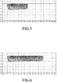
- the multi-segment vehicle turning light lamp generates an optical shape as shown in Figure 6 .
- the first light-emitting element 311, the second light-emitting element 312 and the third light emitting element 313 will emit light together to generate an optical shape as shown in Figure 7 .
- the partitions 241, the substrate 22 and the lens 23 cooperate to define the first light-exit channel 251, the second light-exit channel 252 and the third light-exit channel 253, through this arrangement, the light beams of the first light emitting element 311, the second light emitting element 312 and the third light emitting element 313 can be controlled separately, so as to achieve the multi-segmented illumination as shown in Figures 5 to 7 .
- Each of the partitions 241 has a reflection surface for reflecting light emitted from a respective one of the first, second and third light-emitting elements 311, 312, 313, so that the multi-segment turning light possesses better light extraction efficiency compared with the partitions with black light-absorbing surfaces.
- the configuration that the central angle (A2) of each of the first light-exit channel 251, the second light-exit channel 252 and the third light-exit channel 253 is substantially 30 degrees provides a distinct visual effect in the change of optical shape, thus creating a sense of style and technology.
- first, second and third light-emitting elements 311, 312, 313 are horizontally spaced with four sides of each of the first, second and third light-emitting members 311, 312, 313 extending in the horizontal direction or the vertical direction, the first, second and third light-emitting elements 311, 312, 313 generate light beams parallel to the road surface and being more adaptive to the lighting of the road surface, thereby further enhance the road safety.
- the first, second and third light-emitting elements 311, 312, 313 integrated on the substrate 22 are cooperated with the construction of radially disposed partitions 241 to provide a simplified overall design of the multi-segment vehicle turning light lamp.
- the effect of the multi-segment vehicle turning light lamp of the present disclosure resides in that, the first, second and third light-emitting elements 311, 312, 313 are integrated on the substrate 22 and cooperate with the first, second and third light-exit channels 251, 252, 253 defined between the partitions 241 to enable multi-segmented illumination, and the overall design is concise.
Abstract
Description
- The disclosure relates to a light lamp for a vehicle, more particularly to a multi-segment vehicle turning light lamp which is configured for multi-segmented illuminatinon and can be used in vehicles with three or more wheels.
- Referring to
Figure 1 , a conventional turning light lamp is mounted on the outer side of aheadlight 11 which acts as a main illumination source of a vehicle and which has an optical axis extending in a front-rear direction. The conventional turning light lamp includes acurved reflector 12, and ahalogen bulb 13 disposed with respect to thereflector 12. Such a turning light lamp can provide illumination in addition to the illumination provided by theheadlight 11 while the vehicle is turning, such that the vehicle turning safety can be enhanced. However, the above-mentioned turning light lamp is bulky and provides only single-segment lighting. - Therefore, the object of the disclosure is to provide a multi-segment vehicle turning light lamp to overcome at least one disadvantage of the prior art.
- According to the disclosure, the multi-segment vehicle turning light lamp includes a lamp housing assembly and a lighting assembly.
- The lamp housing assembly includes a substrate having a plane surface, a lens disposed in front of the substrate and having a concave inner surface that faces the substrate, and a light divider arrangement disposed between the substrate and the lens. The light divider arrangement includes a plurality of partitions that are angularly arranged with respect to a center of curvature of the concave inner surface of the lens and that extend radially to the lens. The plurality of partitions, the substrate and the lens cooperate to define a plurality of light-exit channels. The lighting assembly includes a plurality of light-emitting elements disposed on the plane surface of the substrate. Each of the light-emitting elements is disposed for emitting light through a respective one of the light-exit channels.
- Other features and advantages of the disclosure will become apparent in the following detailed description of the embodiment with reference to the accompanying drawings, of which:
-
Figure 1 is a cross-sectional view of a conventional turning light lamp; -
Figure 2 is an exploded perspective view of an embodiment of a multi-segment vehicle turning light lamp according to the present disclosure; -
Figure 3 is an assembled cross-sectional view illustrating the embodiment; -
Figure 4 is a front view of the embodiment, the angle of vision is toward a lens of the embodiment; -
Figure 5 is a representation of an optical shape while a first light-emitting element of the embodiment projects light; -
Figure 6 is a representation of an optical shape while the first light-emitting element and a second light-emitting element project light; and -
Figure 7 is a representation of an optical shape while the first and second light-emitting elements and a third light-emitting element project light. - As shown in
Figures 2 to 4 , an embodiment of the multi-segment turning light lamp according to the present disclosure can be mounted by the side of a headlight (not shown) of a vehicle. The headlight emits light along an optical axis extending in a front-rear direction (D1). - The multi-segment turning light lamp includes a
lamp housing assembly 2 and alighting assembly 3. - The
lamp housing assembly 2 includes a substantiallyU-shaped lamp holder 21, asubstrate 22 fixed on thelamp holder 21, alens 23 disposed in front of and spaced from thesubstrate 22, alight divider arrangement 24 provided between thesubstrate 22 and thelens 23, and upper andlower lamp shells 26 disposed respectively on upper and lower sides of thesubstrate 22, thelens 23 and thelight divider arrangement 24. Thesubstrate 22 has a plane surface. A direction (D2) normal to the plane surface of thesubstrate 22 is inclined to the front-rear direction (D1). - The
lamp holder 21 includes abase portion 211 which is perpendicular to the direction (D2) which is normal to the plane surface of thesubstrate 22, and a pair ofside wing portions 212 extending respectively from opposite ends of thebase portion 211. - An angle (A1) included between the direction (D2) and the front-rear direction (D1) is 45 degrees. The
substrate 22 is of a rectangular shape and is fixed on thebase portion 211 of thelamp holder 21. - Referring to
Figures 2 and3 , thelens 23 is disposed in front of thelight divider arrangement 24, and includes a concaveinner surface 231 facing the plane surface of thesubstrate 22. The arc length in a cross-section of the concaveinner surface 231 is a quarter of circle, and the center of curvature of the concaveinner surface 231 is designated as a reference point (P1). - The
light divider arrangement 24 includes a plurality ofpartitions 241 that are angularly arranged with respect to the reference point (PI) and that extend radially to thelens 23. Eachpartition 241 is a reflector of substantial rectangular shape for reflecting light. Thepartitions 241, thesubstrate 22 and thelens 23 cooperate to define a plurality of substantially fan-shaped light-exit channels behind the lens 23 (i.e., thelens 23 is disposed in front of the light-exit channels). In this embodiment, the light-exit channels as seen inFigure 3 has, from left to right, a first light-exit channel 251, a second light-exit channel 252, and a third light-exit channel 253. Each of the first, second, and third light-exit channels exit channels - The upper and
lower lamp shells 26 cooperate with thelamp holder 21 to define ahousing space 27 into which thesubstrate 22, the light-divider arrangement 24 and thelighting assembly 3 are received. Each of the upper andlower lamp shells 26 has a substantially fan-shaped base 261 and a pair oftabs 262. Thebases 261 of the upper andlower lamp shells 26 cover respectively upper and lower sides of the housing space 27 (i.e., cover respectively upper and lower sides of thesubstrate 22, thelens 23 and the light divider arrangement 24) . Thebase 261 of theupper lamp shell 26 is formed with a plurality ofslots 263 retaining respectively upper end portions of thepartitions 241, and thebase 261 of thelower lamp shell 26 is formed with a plurality ofslots 263 retaining respectively lower end portions of thepartitions 241, such that thepartitions 241 are held in place. The pair oftabs 262 of each of the upper andlower lamp shells 26 extend respectively from opposite ends of a front edge of thebase 261 toward the other one of the upper andlower lamp shells 26. Thetabs 262 of the upper andlower lamp shells 26 wrap around front ends of theside wing portions 212 of thelamp holder 21. - The
lighting assembly 3 includes a plurality of light-emitting elements, which are horizontally laid on the plane surface of thesubstrate 22 at intervals. In this embodiment, the light-emitting elements include a first light-emittingelement 311, a secondlight emitting element 312, and a third light-emittingelement 313 that are disposed for emitting light through a respective one of the first, second and third light-exit channels - Each of the first, second and third light-
emitting elements elements elements elements substrate 22, that is, the light-emittingelements - Referring to
Figures 3 and5 to 7 , the multi-segment vehicle turning light lamp according to the disclosure can provide multi-segmented illumination with different illumination ranges depending on the steering angle of the vehicle while turning. - In the event of a small steering angle of the vehicle while turning, the first
light emitting element 311 will emit and project light forward in the direction (D2), but the secondlight emitting element 312 and the thirdlight emitting element 313 do not emit light. At this time, the multi-segment vehicle turning light lamp produces an optical shape as shown inFigure 5 . In the event of a medium steering angle of the vehicle while turning, the first light-emittingelement 311 and the second light-emittingelement 312 both emit and project light forward in the direction (D2), but the third light-emittingelement 313 does not emit light. At this time, the multi-segment vehicle turning light lamp generates an optical shape as shown inFigure 6 . In the event of a large steering angle of the vehicle while turning, the first light-emittingelement 311, the second light-emittingelement 312 and the thirdlight emitting element 313 will emit light together to generate an optical shape as shown inFigure 7 . - The
partitions 241, thesubstrate 22 and thelens 23 cooperate to define the first light-exit channel 251, the second light-exit channel 252 and the third light-exit channel 253, through this arrangement, the light beams of the firstlight emitting element 311, the secondlight emitting element 312 and the thirdlight emitting element 313 can be controlled separately, so as to achieve the multi-segmented illumination as shown inFigures 5 to 7 . Each of thepartitions 241 has a reflection surface for reflecting light emitted from a respective one of the first, second and third light-emittingelements - In this embodiment, the configuration that the central angle (A2) of each of the first light-
exit channel 251, the second light-exit channel 252 and the third light-exit channel 253 is substantially 30 degrees provides a distinct visual effect in the change of optical shape, thus creating a sense of style and technology. - In addition, since the first, second and third light-emitting
elements members elements emitting elements substrate 22 are cooperated with the construction of radially disposedpartitions 241 to provide a simplified overall design of the multi-segment vehicle turning light lamp. - In summary, the effect of the multi-segment vehicle turning light lamp of the present disclosure resides in that, the first, second and third light-
emitting elements substrate 22 and cooperate with the first, second and third light-exit channels partitions 241 to enable multi-segmented illumination, and the overall design is concise. - In the description above, for the purposes of explanation, numerous specific details have been set forth in order to provide a thorough understanding of the embodiment. It will be apparent, however, to one skilled in the art, that one or more other embodiments may be practiced without some of these specific details. It should also be appreciated that reference throughout this specification to "one embodiment," "an embodiment," an embodiment with an indication of an ordinal number and so forth means that a particular feature, structure, or characteristic may be included in the practice of the disclosure. It should be further appreciated that in the description, various features are sometimes grouped together in a single embodiment, figure, or description thereof for the purpose of streamlining the disclosure and aiding in the understanding of various inventive aspects, and that one or more features or specific details from one embodiment may be practiced together with one or more features or specific details from another embodiment, where appropriate, in the practice of the disclosure.
Claims (9)
- A multi-segment turning light lamp for a vehicle, characterized by:a lamp housing assembly (2) including a substrate (22) that has a plane surface, a lens (23) disposed in front of said substrate (22) and having a concave inner surface (231) that faces said substrate (22), and a light divider arrangement (24) disposed between said substrate (22) and said lens (23), said light divider arrangement (24) including a plurality of partitions (241) that are angularly arranged with respect to a center of curvature (P1) of said concave inner surface (231) of said lens (23) and that extend radially to said lens (23), said plurality of partitions (241), said substrate (22) and said lens (23) cooperating to define a plurality of light-exit channels (251, 252, 253) ; anda lighting assembly (3) including a plurality of light-emitting elements (311,312,313) that are disposed on said plane surface of said substrate (22), each of said light-emitting elements (311,312,313) being disposed for emitting light through a respective one of said light-exit channels (251,252,253).
- The multi-segment turning light lamp as claimed in Claim 1, characterized in that each of said light-exit channels (251,252,253) is of substantial fan-shape, said lamp housing assembly (2) further including upper and lower lamp shells (26) that cover respectively upper and lower sides of said substrate (22), said lens (23) and said light divider arrangement (24).
- The multi-segment turning light lamp as claimed in Claim 1, characterized in that each of said light-exit channels (251,252,253) is of substantial fan-shape, said lens (23) being disposed in front of said plurality of light-exit channels (251,252,253).
- The multi-segment turning light lamp as claimed in Claim 1, characterized in that each of said light-exit channels (251,252,253) is of substantial fan-shape, and each of said light-exit channels (251, 252, 253) has the same central angle.
- The multi-segment turning light lamp as claimed in Claim 4, characterized in that the central angle of each light-exit channel (251,252,253) is substantially 30 degrees.
- The multi-segment turning light lamp as claimed in any one of Claims 1 to 5, characterized in that each of said light-emitting elements (311,312,313) is of rectangular shape with four sides extending in a horizontal direction or a vertical direction.
- The multi-segment turning light lamp as claimed in Claim 6, characterized in that each of said light-emitting elements (311,312,313) is a light emitting diode chip.
- The multi-segment turning light lamp as claimed in any one of Claims 6 and 7, characterized in that an optical axis of each of said light-emitting elements (311,312,313) extends in a direction normal to said plane surface of said substrate.
- The multi-segment turning light lamp as claimed in any one of the previous Claims, characterized in that each of said partitions (241) includes a reflection surface for reflecting light emitted from a respective one of said light-emitting elements (311, 312, 313).
Priority Applications (2)
| Application Number | Priority Date | Filing Date | Title |
|---|---|---|---|
| ES19195625T ES2935638T3 (en) | 2019-09-05 | 2019-09-05 | Multi-segment Vehicle Turn Signal Lamp |
| EP19195625.9A EP3789660B1 (en) | 2019-09-05 | 2019-09-05 | Multi-segment vehicle turning light lamp |
Applications Claiming Priority (1)
| Application Number | Priority Date | Filing Date | Title |
|---|---|---|---|
| EP19195625.9A EP3789660B1 (en) | 2019-09-05 | 2019-09-05 | Multi-segment vehicle turning light lamp |
Publications (2)
| Publication Number | Publication Date |
|---|---|
| EP3789660A1 true EP3789660A1 (en) | 2021-03-10 |
| EP3789660B1 EP3789660B1 (en) | 2022-10-26 |
Family
ID=67874343
Family Applications (1)
| Application Number | Title | Priority Date | Filing Date |
|---|---|---|---|
| EP19195625.9A Active EP3789660B1 (en) | 2019-09-05 | 2019-09-05 | Multi-segment vehicle turning light lamp |
Country Status (2)
| Country | Link |
|---|---|
| EP (1) | EP3789660B1 (en) |
| ES (1) | ES2935638T3 (en) |
Citations (4)
| Publication number | Priority date | Publication date | Assignee | Title |
|---|---|---|---|---|
| US20110038168A1 (en) * | 2008-04-25 | 2011-02-17 | Koninklijke Philips Electronics N.V. | Lamp assembly |
| US20110260616A1 (en) * | 2010-04-22 | 2011-10-27 | Ford Global Technologies, Llc | Vehicle exterior lamp |
| EP3418626A1 (en) * | 2016-02-15 | 2018-12-26 | LG Innotek Co., Ltd. | Lamp and vehicle having same |
| WO2019029977A1 (en) * | 2017-08-08 | 2019-02-14 | Osram Gmbh | Luminaire having two light sources and an optic |
-
2019
- 2019-09-05 ES ES19195625T patent/ES2935638T3/en active Active
- 2019-09-05 EP EP19195625.9A patent/EP3789660B1/en active Active
Patent Citations (4)
| Publication number | Priority date | Publication date | Assignee | Title |
|---|---|---|---|---|
| US20110038168A1 (en) * | 2008-04-25 | 2011-02-17 | Koninklijke Philips Electronics N.V. | Lamp assembly |
| US20110260616A1 (en) * | 2010-04-22 | 2011-10-27 | Ford Global Technologies, Llc | Vehicle exterior lamp |
| EP3418626A1 (en) * | 2016-02-15 | 2018-12-26 | LG Innotek Co., Ltd. | Lamp and vehicle having same |
| WO2019029977A1 (en) * | 2017-08-08 | 2019-02-14 | Osram Gmbh | Luminaire having two light sources and an optic |
Also Published As
| Publication number | Publication date |
|---|---|
| ES2935638T3 (en) | 2023-03-08 |
| EP3789660B1 (en) | 2022-10-26 |
Similar Documents
| Publication | Publication Date | Title |
|---|---|---|
| US7661860B2 (en) | Lighting and/or signalling device for a motor vehicle | |
| CN106838759B (en) | Lighting device for vehicle | |
| JP6690960B2 (en) | Vehicle lighting | |
| US20040145910A1 (en) | Lighting assembly | |
| WO2019225645A1 (en) | Vehicle lamp | |
| JP6690961B2 (en) | Vehicle lighting | |
| JP2020024793A (en) | Vehicular lighting system | |
| JP6933901B2 (en) | Vehicle lighting | |
| JP2004139903A (en) | Vehicular lighting device | |
| JP2019012623A (en) | Vehicular lighting fixture | |
| US10738962B1 (en) | Multi-segment vehicle turning light lamp | |
| EP3789660A1 (en) | Multi-segment vehicle turning light lamp | |
| US10436405B2 (en) | Lighting module for the lighting and/or signalling of a motor vehicle | |
| JP6059599B2 (en) | Vehicle lighting | |
| JP4499642B2 (en) | Vehicle lighting | |
| CN107228322B (en) | Beam shaper for aircraft headlights and hybrid headlight for aircraft | |
| JP2017183143A (en) | Vehicular lighting tool | |
| TWI675763B (en) | Multi-section car turn signal device | |
| KR102118140B1 (en) | Lamp for vehicle | |
| US20180023783A1 (en) | Method and apparatus for subtending light downwardly | |
| JP5452241B2 (en) | Tail stop lamp | |
| JP7255951B2 (en) | Vehicle lighting unit and vehicle lighting | |
| US11555592B1 (en) | Lamp for vehicle and vehicle including the same | |
| KR20130100652A (en) | Lamp for automobile | |
| JP7467500B2 (en) | Vehicle headlights |
Legal Events
| Date | Code | Title | Description |
|---|---|---|---|
| PUAI | Public reference made under article 153(3) epc to a published international application that has entered the european phase |
Free format text: ORIGINAL CODE: 0009012 |
|
| STAA | Information on the status of an ep patent application or granted ep patent |
Free format text: STATUS: REQUEST FOR EXAMINATION WAS MADE |
|
| 17P | Request for examination filed |
Effective date: 20190905 |
|
| AK | Designated contracting states |
Kind code of ref document: A1 Designated state(s): AL AT BE BG CH CY CZ DE DK EE ES FI FR GB GR HR HU IE IS IT LI LT LU LV MC MK MT NL NO PL PT RO RS SE SI SK SM TR |
|
| AX | Request for extension of the european patent |
Extension state: BA ME |
|
| GRAP | Despatch of communication of intention to grant a patent |
Free format text: ORIGINAL CODE: EPIDOSNIGR1 |
|
| STAA | Information on the status of an ep patent application or granted ep patent |
Free format text: STATUS: GRANT OF PATENT IS INTENDED |
|
| INTG | Intention to grant announced |
Effective date: 20220524 |
|
| GRAS | Grant fee paid |
Free format text: ORIGINAL CODE: EPIDOSNIGR3 |
|
| GRAA | (expected) grant |
Free format text: ORIGINAL CODE: 0009210 |
|
| STAA | Information on the status of an ep patent application or granted ep patent |
Free format text: STATUS: THE PATENT HAS BEEN GRANTED |
|
| AK | Designated contracting states |
Kind code of ref document: B1 Designated state(s): AL AT BE BG CH CY CZ DE DK EE ES FI FR GB GR HR HU IE IS IT LI LT LU LV MC MK MT NL NO PL PT RO RS SE SI SK SM TR |
|
| REG | Reference to a national code |
Ref country code: GB Ref legal event code: FG4D |
|
| REG | Reference to a national code |
Ref country code: CH Ref legal event code: EP |
|
| REG | Reference to a national code |
Ref country code: AT Ref legal event code: REF Ref document number: 1527270 Country of ref document: AT Kind code of ref document: T Effective date: 20221115 |
|
| REG | Reference to a national code |
Ref country code: DE Ref legal event code: R096 Ref document number: 602019021008 Country of ref document: DE |
|
| REG | Reference to a national code |
Ref country code: IE Ref legal event code: FG4D |
|
| REG | Reference to a national code |
Ref country code: LT Ref legal event code: MG9D |
|
| REG | Reference to a national code |
Ref country code: NL Ref legal event code: MP Effective date: 20221026 |
|
| REG | Reference to a national code |
Ref country code: ES Ref legal event code: FG2A Ref document number: 2935638 Country of ref document: ES Kind code of ref document: T3 Effective date: 20230308 |
|
| REG | Reference to a national code |
Ref country code: AT Ref legal event code: MK05 Ref document number: 1527270 Country of ref document: AT Kind code of ref document: T Effective date: 20221026 |
|
| PG25 | Lapsed in a contracting state [announced via postgrant information from national office to epo] |
Ref country code: NL Free format text: LAPSE BECAUSE OF FAILURE TO SUBMIT A TRANSLATION OF THE DESCRIPTION OR TO PAY THE FEE WITHIN THE PRESCRIBED TIME-LIMIT Effective date: 20221026 |
|
| PG25 | Lapsed in a contracting state [announced via postgrant information from national office to epo] |
Ref country code: SE Free format text: LAPSE BECAUSE OF FAILURE TO SUBMIT A TRANSLATION OF THE DESCRIPTION OR TO PAY THE FEE WITHIN THE PRESCRIBED TIME-LIMIT Effective date: 20221026 Ref country code: PT Free format text: LAPSE BECAUSE OF FAILURE TO SUBMIT A TRANSLATION OF THE DESCRIPTION OR TO PAY THE FEE WITHIN THE PRESCRIBED TIME-LIMIT Effective date: 20230227 Ref country code: NO Free format text: LAPSE BECAUSE OF FAILURE TO SUBMIT A TRANSLATION OF THE DESCRIPTION OR TO PAY THE FEE WITHIN THE PRESCRIBED TIME-LIMIT Effective date: 20230126 Ref country code: LT Free format text: LAPSE BECAUSE OF FAILURE TO SUBMIT A TRANSLATION OF THE DESCRIPTION OR TO PAY THE FEE WITHIN THE PRESCRIBED TIME-LIMIT Effective date: 20221026 Ref country code: FI Free format text: LAPSE BECAUSE OF FAILURE TO SUBMIT A TRANSLATION OF THE DESCRIPTION OR TO PAY THE FEE WITHIN THE PRESCRIBED TIME-LIMIT Effective date: 20221026 Ref country code: AT Free format text: LAPSE BECAUSE OF FAILURE TO SUBMIT A TRANSLATION OF THE DESCRIPTION OR TO PAY THE FEE WITHIN THE PRESCRIBED TIME-LIMIT Effective date: 20221026 |
|
| PG25 | Lapsed in a contracting state [announced via postgrant information from national office to epo] |
Ref country code: RS Free format text: LAPSE BECAUSE OF FAILURE TO SUBMIT A TRANSLATION OF THE DESCRIPTION OR TO PAY THE FEE WITHIN THE PRESCRIBED TIME-LIMIT Effective date: 20221026 Ref country code: PL Free format text: LAPSE BECAUSE OF FAILURE TO SUBMIT A TRANSLATION OF THE DESCRIPTION OR TO PAY THE FEE WITHIN THE PRESCRIBED TIME-LIMIT Effective date: 20221026 Ref country code: LV Free format text: LAPSE BECAUSE OF FAILURE TO SUBMIT A TRANSLATION OF THE DESCRIPTION OR TO PAY THE FEE WITHIN THE PRESCRIBED TIME-LIMIT Effective date: 20221026 Ref country code: IS Free format text: LAPSE BECAUSE OF FAILURE TO SUBMIT A TRANSLATION OF THE DESCRIPTION OR TO PAY THE FEE WITHIN THE PRESCRIBED TIME-LIMIT Effective date: 20230226 Ref country code: HR Free format text: LAPSE BECAUSE OF FAILURE TO SUBMIT A TRANSLATION OF THE DESCRIPTION OR TO PAY THE FEE WITHIN THE PRESCRIBED TIME-LIMIT Effective date: 20221026 Ref country code: GR Free format text: LAPSE BECAUSE OF FAILURE TO SUBMIT A TRANSLATION OF THE DESCRIPTION OR TO PAY THE FEE WITHIN THE PRESCRIBED TIME-LIMIT Effective date: 20230127 |
|
| REG | Reference to a national code |
Ref country code: DE Ref legal event code: R097 Ref document number: 602019021008 Country of ref document: DE |
|
| PG25 | Lapsed in a contracting state [announced via postgrant information from national office to epo] |
Ref country code: SM Free format text: LAPSE BECAUSE OF FAILURE TO SUBMIT A TRANSLATION OF THE DESCRIPTION OR TO PAY THE FEE WITHIN THE PRESCRIBED TIME-LIMIT Effective date: 20221026 Ref country code: RO Free format text: LAPSE BECAUSE OF FAILURE TO SUBMIT A TRANSLATION OF THE DESCRIPTION OR TO PAY THE FEE WITHIN THE PRESCRIBED TIME-LIMIT Effective date: 20221026 Ref country code: EE Free format text: LAPSE BECAUSE OF FAILURE TO SUBMIT A TRANSLATION OF THE DESCRIPTION OR TO PAY THE FEE WITHIN THE PRESCRIBED TIME-LIMIT Effective date: 20221026 Ref country code: DK Free format text: LAPSE BECAUSE OF FAILURE TO SUBMIT A TRANSLATION OF THE DESCRIPTION OR TO PAY THE FEE WITHIN THE PRESCRIBED TIME-LIMIT Effective date: 20221026 Ref country code: CZ Free format text: LAPSE BECAUSE OF FAILURE TO SUBMIT A TRANSLATION OF THE DESCRIPTION OR TO PAY THE FEE WITHIN THE PRESCRIBED TIME-LIMIT Effective date: 20221026 |
|
| PG25 | Lapsed in a contracting state [announced via postgrant information from national office to epo] |
Ref country code: SK Free format text: LAPSE BECAUSE OF FAILURE TO SUBMIT A TRANSLATION OF THE DESCRIPTION OR TO PAY THE FEE WITHIN THE PRESCRIBED TIME-LIMIT Effective date: 20221026 Ref country code: AL Free format text: LAPSE BECAUSE OF FAILURE TO SUBMIT A TRANSLATION OF THE DESCRIPTION OR TO PAY THE FEE WITHIN THE PRESCRIBED TIME-LIMIT Effective date: 20221026 |
|
| PLBE | No opposition filed within time limit |
Free format text: ORIGINAL CODE: 0009261 |
|
| STAA | Information on the status of an ep patent application or granted ep patent |
Free format text: STATUS: NO OPPOSITION FILED WITHIN TIME LIMIT |
|
| 26N | No opposition filed |
Effective date: 20230727 |
|
| PG25 | Lapsed in a contracting state [announced via postgrant information from national office to epo] |
Ref country code: SI Free format text: LAPSE BECAUSE OF FAILURE TO SUBMIT A TRANSLATION OF THE DESCRIPTION OR TO PAY THE FEE WITHIN THE PRESCRIBED TIME-LIMIT Effective date: 20221026 |
|
| PGFP | Annual fee paid to national office [announced via postgrant information from national office to epo] |
Ref country code: DE Payment date: 20230829 Year of fee payment: 5 |
|
| PGFP | Annual fee paid to national office [announced via postgrant information from national office to epo] |
Ref country code: ES Payment date: 20231017 Year of fee payment: 5 |
|
| REG | Reference to a national code |
Ref country code: CH Ref legal event code: PL |