EP3789642B1 - Sicherheitsventil - Google Patents
Sicherheitsventil Download PDFInfo
- Publication number
- EP3789642B1 EP3789642B1 EP20193791.9A EP20193791A EP3789642B1 EP 3789642 B1 EP3789642 B1 EP 3789642B1 EP 20193791 A EP20193791 A EP 20193791A EP 3789642 B1 EP3789642 B1 EP 3789642B1
- Authority
- EP
- European Patent Office
- Prior art keywords
- valve part
- base body
- elastic element
- valve
- outlet opening
- Prior art date
- Legal status (The legal status is an assumption and is not a legal conclusion. Google has not performed a legal analysis and makes no representation as to the accuracy of the status listed.)
- Active
Links
Images


Classifications
-
- F—MECHANICAL ENGINEERING; LIGHTING; HEATING; WEAPONS; BLASTING
- F16—ENGINEERING ELEMENTS AND UNITS; GENERAL MEASURES FOR PRODUCING AND MAINTAINING EFFECTIVE FUNCTIONING OF MACHINES OR INSTALLATIONS; THERMAL INSULATION IN GENERAL
- F16K—VALVES; TAPS; COCKS; ACTUATING-FLOATS; DEVICES FOR VENTING OR AERATING
- F16K24/00—Devices, e.g. valves, for venting or aerating enclosures
- F16K24/04—Devices, e.g. valves, for venting or aerating enclosures for venting only
-
- F—MECHANICAL ENGINEERING; LIGHTING; HEATING; WEAPONS; BLASTING
- F16—ENGINEERING ELEMENTS AND UNITS; GENERAL MEASURES FOR PRODUCING AND MAINTAINING EFFECTIVE FUNCTIONING OF MACHINES OR INSTALLATIONS; THERMAL INSULATION IN GENERAL
- F16K—VALVES; TAPS; COCKS; ACTUATING-FLOATS; DEVICES FOR VENTING OR AERATING
- F16K17/00—Safety valves; Equalising valves, e.g. pressure relief valves
- F16K17/02—Safety valves; Equalising valves, e.g. pressure relief valves opening on surplus pressure on one side; closing on insufficient pressure on one side
- F16K17/04—Safety valves; Equalising valves, e.g. pressure relief valves opening on surplus pressure on one side; closing on insufficient pressure on one side spring-loaded
- F16K17/0413—Safety valves; Equalising valves, e.g. pressure relief valves opening on surplus pressure on one side; closing on insufficient pressure on one side spring-loaded in the form of closure plates
-
- F—MECHANICAL ENGINEERING; LIGHTING; HEATING; WEAPONS; BLASTING
- F16—ENGINEERING ELEMENTS AND UNITS; GENERAL MEASURES FOR PRODUCING AND MAINTAINING EFFECTIVE FUNCTIONING OF MACHINES OR INSTALLATIONS; THERMAL INSULATION IN GENERAL
- F16K—VALVES; TAPS; COCKS; ACTUATING-FLOATS; DEVICES FOR VENTING OR AERATING
- F16K17/00—Safety valves; Equalising valves, e.g. pressure relief valves
- F16K17/02—Safety valves; Equalising valves, e.g. pressure relief valves opening on surplus pressure on one side; closing on insufficient pressure on one side
- F16K17/04—Safety valves; Equalising valves, e.g. pressure relief valves opening on surplus pressure on one side; closing on insufficient pressure on one side spring-loaded
- F16K17/044—Safety valves; Equalising valves, e.g. pressure relief valves opening on surplus pressure on one side; closing on insufficient pressure on one side spring-loaded with more than one spring
-
- F—MECHANICAL ENGINEERING; LIGHTING; HEATING; WEAPONS; BLASTING
- F16—ENGINEERING ELEMENTS AND UNITS; GENERAL MEASURES FOR PRODUCING AND MAINTAINING EFFECTIVE FUNCTIONING OF MACHINES OR INSTALLATIONS; THERMAL INSULATION IN GENERAL
- F16K—VALVES; TAPS; COCKS; ACTUATING-FLOATS; DEVICES FOR VENTING OR AERATING
- F16K17/00—Safety valves; Equalising valves, e.g. pressure relief valves
- F16K17/02—Safety valves; Equalising valves, e.g. pressure relief valves opening on surplus pressure on one side; closing on insufficient pressure on one side
- F16K17/04—Safety valves; Equalising valves, e.g. pressure relief valves opening on surplus pressure on one side; closing on insufficient pressure on one side spring-loaded
- F16K17/0493—Safety valves; Equalising valves, e.g. pressure relief valves opening on surplus pressure on one side; closing on insufficient pressure on one side spring-loaded with a spring other than a helicoidal spring
-
- H—ELECTRICITY
- H01—ELECTRIC ELEMENTS
- H01M—PROCESSES OR MEANS, e.g. BATTERIES, FOR THE DIRECT CONVERSION OF CHEMICAL ENERGY INTO ELECTRICAL ENERGY
- H01M50/00—Constructional details or processes of manufacture of the non-active parts of electrochemical cells other than fuel cells, e.g. hybrid cells
- H01M50/30—Arrangements for facilitating escape of gases
- H01M50/342—Non-re-sealable arrangements
-
- Y—GENERAL TAGGING OF NEW TECHNOLOGICAL DEVELOPMENTS; GENERAL TAGGING OF CROSS-SECTIONAL TECHNOLOGIES SPANNING OVER SEVERAL SECTIONS OF THE IPC; TECHNICAL SUBJECTS COVERED BY FORMER USPC CROSS-REFERENCE ART COLLECTIONS [XRACs] AND DIGESTS
- Y02—TECHNOLOGIES OR APPLICATIONS FOR MITIGATION OR ADAPTATION AGAINST CLIMATE CHANGE
- Y02E—REDUCTION OF GREENHOUSE GAS [GHG] EMISSIONS, RELATED TO ENERGY GENERATION, TRANSMISSION OR DISTRIBUTION
- Y02E60/00—Enabling technologies; Technologies with a potential or indirect contribution to GHG emissions mitigation
- Y02E60/10—Energy storage using batteries
Definitions
- the invention relates to a safety valve, in particular for a housing such as a battery housing, with a base body, at least one elastic element and a valve part, with the elastic element prestressing the valve part into a closed position, with the valve part bearing against the base body in the closed position and at least one outlet opening of the base body closes, the elastic element being integrally connected to the base body.
- Safety valves or pressure relief valves, are used to vent rooms when the pressure in the room exceeds a certain limit.
- the safety valve can be designed to be able to be opened several times as intended, or to be used only once and, once the limit pressure has been exceeded, maintenance or replacement is necessary.
- Such spaces are usually closed off by housing spaces which are filled with a fluid such as a gas or a liquid.
- a fluid such as a gas or a liquid.
- safety valves are used to drain fluid if the battery is destroyed, in order to avoid an uncontrolled explosion of the housing.
- WO 2005/108835 A1 discloses a valve having a body and a blade member inserted in the body, the blade member having a connection to the body and resilient members supporting a valve portion.
- the elastic elements are placed in the base body, as a result of which the elastic elements pretension the valve part in relation to the base body. Then another part of the base body is put on to fix and protect the leaf element.
- Such an embodiment is relatively complex to construct and is therefore also quite error-prone during assembly.
- the leaf element is made of metal in one piece, which is disadvantageous, however, since the quality and stability of the valve part cannot be selected independently of the properties of the elastic elements. Due to the thermal coupling, the elastic elements may be heated via the valve part, which can lead to changes in elasticity and thus changes in the limit temperature at which the valve opens.
- valves of the specified type show valves of the specified type. However, all of these valves have in common that to assemble the valve part on a lower or upper housing part is arranged, and then the corresponding other housing part is placed on top or attached below. This is complex and forces the insertion of the valve part already when assembling the housing.
- the object of the invention is therefore to provide a safety valve of the type mentioned which enables easier assembly.
- valve part can be inserted between the elastic element and a bearing surface of the base body arranged around the outlet opening.
- the one-piece embodiment means that the elastic elements can be connected directly to the base body when it is manufactured or are manufactured together with it.
- the entire base body can thus be produced in one piece and the valve part can be arranged in the base body in a second step.
- An embodiment made of only two pieces is thus possible, that is to say one which is particularly simple, inexpensive and can be produced quickly. In addition, assembly is also facilitated since only two parts need to be brought together.
- the material of the valve part can be determined independently of the material of the elastic element.
- the valve part that comes into most intensive contact with the space to be sealed can thus be selected so that it withstands the thermal or chemical demands well, but the elastic element nevertheless always presses the valve part onto the outlet opening with the intended force.
- the outlet opening is an opening which is delimited by the base body and is flow-connected to the space to be secured.
- the pressure in the area of the outlet opening essentially corresponds to the internal pressure of the space, for example the interior of a housing.
- the outlet opening is usually arranged above an opening in a wall of the room.
- An elastic element means an element that can be bent elastically at least to the extent that it presses and prestresses the valve part against the base body.
- the elastic element does not necessarily have to be so elastic that it only bends elastically when the valve is opened, ie when a threshold or limit pressure is exceeded. Provision can also be made for the elastic element to be plastically deformed or broken when it is opened.
- the body may be designed to be built into or attached to a sealing surface, such as a battery case wall.
- the base body can also be connected in one piece to the sealing surface.
- the closed position means a position of the safety valve in which the valve part rests on the outlet opening and closes it. It is therefore the intended, operational position of the valve that it assumes when the limit pressure at which it opens has not been exceeded.
- valve part can be inserted between the elastic element and a bearing surface of the base body arranged around the outlet opening.
- the valve body preferably has a tight connection to the bearing surface in the installed position. If the mostly flat valve part is inserted between the elastic element and the bearing surface, it can be provided that the elastic element is automatically lifted and a pretension is generated by the insertion movement, i.e. a movement which is at least partially parallel to the bearing surface.
- the elastic element fixes the valve part in the closed position.
- fixing it is meant that the elastic element essentially holds the valve body over the outlet opening, at least until the limit pressure is reached and the valve opens. The elastic element thus prevents the valve body from being displaced as a result of vibrations, unwanted manipulations or slight pressure differences.
- the elastic element fixes the valve part in a form-fitting manner. This can facilitate assembly, since the optimal position of the valve part automatically becomes apparent when the form fit is achieved. Alternatively, there can be a frictional fixing.
- the elastic element and the valve part can also be glued together.
- the valve part has at least one fixing shoulder, on which the elastic element fixes the valve part in a form-fitting manner in the closed position.
- a fixing shoulder means an elevation that limits the movement of the valve part in at least one direction by resting against the elastic element. There can be play between the fixing shoulder and the elastic element.
- at least one fixing shoulder can also be provided, on which the base body or a part of the housing on which the safety valve is arranged, fixes the valve part in the closed position in a form-fitting manner.
- the elastic element is designed as a leaf spring.
- Leaf springs are easy and inexpensive to manufacture and can be easily incorporated during injection molding or other manufacturing processes of the housing.
- valve part has at least one sealing element for sealing the connection between the valve part and the base body in the closed position.
- the base body has a protective cover in the area of the outlet opening and the valve part is arranged between the protective cover and the outlet opening.
- the protective cover can have openings or recesses in order to ensure a flow of fluid at the opening.
- the base body has an insertion opening arranged to the side of the outlet opening for inserting the valve part. This means that the valve part can be positioned quickly and easily in one step.
- the valve part has a main body, preferably made of hard plastic.
- the main body mainly assumes the force-transmitting function between the valve body and the base body and enables a sufficiently firm closure of the outlet opening.
- the main body of the valve part has a centering ring on which the elastic element rests at least partially and centers the valve part.
- Centering means that the valve part is arranged and held centrally above the outlet opening, that is to say is arranged essentially centrally over it. Due to the centering, an optimal position over the outlet opening and thus an optimal closure of this can be achieved.
- valve part has a semi-permeable membrane.
- the semi-permeable membrane can be designed to be permeable to gases or certain gases but impermeable to liquids or certain liquids such as water. As a result, smaller pressure differences between the closed space and the environment can be compensated without risk of contamination.
- the safety valve only opens when the pressure suddenly increases so that the passage capacity of the membrane is exceeded and the threshold pressure is ultimately exceeded.
- the safety valve thus has a dual effect in that, in addition to its function as a safety valve that opens when the threshold pressure is exceeded, it also has a pressure compensation effect under normal conditions.
- the semipermeable membrane is enclosed by the main body of the valve part.
- the membrane is thus supported on all sides by the main body and little mechanical force is exerted on it.
- Figures 1 to 3 show an embodiment in the assembled state, with a base body 1, which has a lower part 5 and a protective cover 7 spaced apart from the lower part 5 via supports 6.
- Two supports 6 are arranged opposite one another on the sides of the lower part 5 , with the result that a channel 8 with two insertion openings 14 is formed between the lower part 5 and the protective cover 7 .
- the protective cover 7 is arranged above the outlet opening 2 and covers it.
- the safety valve is arranged on a housing wall 20 of a battery housing, the battery housing having at least one battery module and being essentially tight.
- the lower part 5 has an outlet opening 2 in the middle, which is designed to be round.
- a connecting surface of the lower part 5 facing away from the protective cover 7 is connected to the housing wall 20 so that the outlet opening 2 is flow-connected to an opening 21 in the housing wall 20 .
- the opening 21 of the housing wall 20 is larger than the outlet opening 2, but is completely surrounded by the base body 1.
- the opening 21 can also be smaller than or the same size as the outlet opening 2 .
- the base body 1 thus closes the opening 21 apart from the outlet opening 2.
- the outlet opening 2 is therefore also in flow connection with the space 22 beyond the housing wall 20.
- a seal 9 is provided on the connecting surface for sealing with the housing wall 20.
- the protective cover 7 has two main beams 10a which delimit several ventilation openings.
- the base body 1 has a total of four elastic elements 3 which are integrally connected to the base body 1 and are arranged uniformly around the outlet opening 2 .
- the elastic members 3 are integrally connected to the protective cover 7 via connecting portions 3a.
- the elastic elements 3 are designed as leaf springs, which extend in the direction of the center of the outlet opening 2, first in the connection area 3a essentially parallel to the outlet opening 2 and then in a spring area 3b in the direction of the outlet opening 2. In addition, they have end areas 3c, which again have a shallower angle to the outlet opening 2 than the spring areas 3b.
- the elastic elements 3 thus essentially have an S-shape in section.
- a valve part 4 is arranged between the elastic elements 3 and the lower part 5, which through the elastic elements 3 presses against a bearing surface 10 of the base body 1, in this case the lower part 5, and thus prestresses (see arrow 15).
- the bearing surface 10 completely encloses the circular outlet opening 2 and the valve part 4 rests continuously around the outlet opening 2 on the bearing surface 10 , with the result that the valve part 4 completely covers the outlet opening 2 .
- a sealing element 11 is provided on the valve part 4 in the area of contact between the valve part 4 and the bearing surface 10 . In this way, the opening in the housing wall 20, over which the safety valve can be arranged, is completely sealed.
- the valve part 4 has a main body 12 with a centrally arranged recess in which a semi-permeable membrane 13 is arranged. Preferably, this membrane 13 is injected into the main body.
- the main body 12 has a centering ring 16 around the circular recess, which serves as a fixing shoulder and is designed as an elevation in relation to the rest of the main body 12 .
- the elastic elements 3 rest against this centering ring 16 in the assembled state, possibly with play, as a result of which the valve part 4 is held by the elastic elements 3 in a form-fitting manner above the outlet opening 2 and is centered by this.
- the end areas 3c prevent the valve part 4 from moving too much in relation to the base body 1. If the valve part 4 is to be removed, at least two elastic elements 3 must be lifted elastically and the valve part 4 must be pushed along the support surface 10 through the channel 8.
- valve body 4 and the base body 1 of this two-part embodiment are brought together.
- the valve body 4 is inserted through an insertion opening 14 into the base body along the bearing surface 10 .
- the base body 1 is embodied symmetrically in relation to a center plane normal to the outlet opening 2 . This has the advantage that it is unimportant via which insertion opening 14 the valve part 4 is inserted.
- the elastic elements 3 are elastically bent upwards by the valve body 4, thus freeing up space for the valve body 4 and prestressing it. Alternatively, it can be provided that the elastic elements 3 are at least partially elastically bent away during the insertion of the valve part 4 from the outlet opening 2 by the assembler or a tool.
Landscapes
- Engineering & Computer Science (AREA)
- General Engineering & Computer Science (AREA)
- Mechanical Engineering (AREA)
- Chemical & Material Sciences (AREA)
- Chemical Kinetics & Catalysis (AREA)
- Electrochemistry (AREA)
- General Chemical & Material Sciences (AREA)
- Safety Valves (AREA)
- Check Valves (AREA)
Description
- Die Erfindung betrifft ein Sicherheitsventil, insbesondere für ein Gehäuse wie ein Batteriegehäuse, mit einem Grundkörper, zumindest einem elastischen Element und einem Ventilteil, wobei das elastische Element den Ventilteil in eine geschlossene Stellung vorspannt, wobei der Ventilteil in der geschlossenen Stellung an dem Grundkörper anliegt und zumindest eine Auslassöffnung des Grundkörpers verschließt, wobei das elastische Element einstückig mit dem Grundkörper verbunden ist.
- Sicherheitsventile, oder auch Überdruckventile, dienen der Entlüftung von Räumen, wenn der Druck im Raum einen bestimmten Grenzwert überschreitet. Dabei kann das Sicherheitsventil dafür ausgelegt sein, mehrmals bestimmungsgemäß öffenbar zu sein, oder nur einmal verwendbar zu sein und, nachdem einmal der Grenzdruck überschritten wurde, eine Wartung oder Ersatz notwendig ist.
- Dabei handelt es sich bei solchen Räumen meist um durch Gehäuse abgeschlossene Räume, welche mit einem Fluid wie Gas oder einer Flüssigkeit gefüllt sind. Insbesondere bei Batteriegehäusen werden solche Sicherheitsventile zum Ablassen von Fluid im Zerstörungsfall der Batterie verwendet, um eine unkontrollierte Explosion des Gehäuses zu vermeiden.
- In der
WO 2005/108835 A1 wird ein Ventil offenbart, welches einen Grundkörper und ein im Grundkörper hineingelegtes Blattelement aufweist, wobei das Blattelement eine Verbindung zum Grundkörper und elastische Elemente aufweist, die einen Ventilteil halten. Die elastischen Elemente werden in den Grundkörper hineingelegt, wodurch die elastischen Elemente den Ventilteil gegenüber dem Grundkörper vorspannen. Danach wird ein weiteres Teil des Grundkörpers zur Fixierung und zum Schutz des Blattelements aufgesetzt. Eine derartige Ausführungsform ist relativ aufwendig im Aufbau und daher auch recht fehleranfällig im Zusammenbau. Um den Zusammenbau möglichst einfach zu halten ist das Blattelement einstückig aus Metall ausgeführt, was jedoch unvorteilhaft ist, da somit die Beschaffenheit und Stabilität des Ventilteils nicht unabhängig von den Eigenschaften der elastischen Elemente gewählt werden kann. Durch die thermische Kopplung werden die elastischen Elemente unter Umständen über den Ventilteil aufgeheizt, was zu Änderungen in der Elastizität und damit Änderungen der Grenztemperatur führen kann, bei der das Ventil öffnet. - Die
JP S522126 U CN 106356486 B ,DE 2537510 A1 ,US 2009/155672 A1 undUS 3,257,237 A zeigen Ventile der angegebenen Art. Jedoch haben all diese Ventile gemein, dass zum Zusammenbau das Ventilteil auf einen unteren oder oberen Gehäuseteil angeordnet wird, und dann das entsprechende andere Gehäuseteil daraufgesetzt oder unten angesetzt wird. Dies ist aufwändig und erzwingt das Einsetzen des Ventilteils bereits bei Zusammenbau des Gehäuses. - Aufgabe der Erfindung ist damit, ein Sicherheitsventil der genannten Art bereitzustellen, welches einen erleichterten Zusammenbau ermöglicht.
- Diese Aufgabe wird erfindungsgemäß dadurch gelöst, dass der Ventilteil zwischen das elastische Element und eine um die Auslassöffnung angeordnete Auflagefläche des Grundkörpers einschiebbar ist.
- Durch die einstückige Ausführungsform wird erreicht, dass die elastischen Elemente schon direkt mit der Herstellung des Grundkörpers mit diesem verbunden werden können oder gemeinsam mit ihm hergestellt werden. Damit kann der gesamte Grundkörper einstückig hergestellt werden und in einem zweiten Schritt der Ventilteil im Grundkörper angeordnet werden. Damit ist eine Ausführungsform aus nur zwei Stücken möglich, also eine besonders einfache, kostengünstige und schnell herzustellende. Darüber hinaus ist auch der Zusammenbau erleichtert, da nur zwei Teile zusammengeführt werden müssen.
- Durch die zweistückige, also trennbare Ausführung des elastischen Elements und dem Ventilteil kann das Material des Ventilteils unabhängig vom Material des elastischen Elements bestimmt werden. Damit kann der Ventilteil, welcher am intensivsten mit dem abzuschließenden Raum in Berührung kommt, so gewählt werden, dass er den thermischen oder chemischen Ansprüchen gut stand hält, das elastische Element aber trotzdem stehts mit vorgesehener Kraft den Ventilteil auf die Auslassöffnung drückt.
- Die Auslassöffnung ist dabei eine Öffnung, welche vom Grundkörper umgrenzt wird und mit dem zu sichernden Raum strömungsverbunden ist. Damit entspricht der Druck im Bereich der Auslassöffnung im Wesentlichen dem Innendruck des Raumes, beispielsweise des Innenraumes eines Gehäuses. Dafür ist die Auslassöffnung in der Regel über einer Öffnung einer Wand des Raumes angeordnet.
- Mit elastischem Element ist dabei ein Element gemeint, dass zumindest soweit elastisch verbiegbar ist, dass es den Ventilteil gegen den Grundkörper drückt und vorspannt. Dabei muss das elastische Element nicht zwangsläufig so elastisch sein, dass es sich bei Öffnen des Ventils, also bei Überschreiten eines Schwellen- oder Grenzdrucks, ausschließlich elastisch verbiegt. Es kann auch vorgesehen sein, dass sich das elastische Element beim Öffnen plastisch verformt oder bricht.
- Es können mehrere elastische Elemente vorgesehen sein, welche vorzugsweise gleichmäßig um den Ventilteil angeordnet sind.
- Der Grundkörper kann zum Einbau oder Anbringen an einer Dichtungsfläche, wie einer Batteriegehäusewand, vorgesehen sein. Dabei kann der Grundkörper auch mit der Dichtungsfläche einstückig verbunden sein.
- Mit geschlossener Stellung ist dabei eine Stellung des Sicherheitsventils gemeint, bei dem der Ventilteil auf der Auslassöffnung aufliegt und diesen verschließt. Es handelt sich also um die bestimmungsgemäße, betriebsmäßige Stellung des Ventils, die es einnimmt, wenn der Grenzdruck, bei dem es öffnet, nicht überschritten wurde.
- Besonders vorteilhaft ist, dass der Ventilteil zwischen das elastische Element und eine um die Auslassöffnung angeordnete Auflagefläche des Grundkörpers einschiebbar ist. Dabei weist der Ventilkörper vorzugsweise eine dichte Verbindung zur Auflagefläche in Einbaustellung auf. Wenn der meist flach ausgeführte Ventilteil zwischen das elastische Element und der Auflagefläche eingeschoben wird, kann vorgesehen sein, dass durch die Einschiebbewegung, also einer Bewegung, welche zumindest teilweise parallel zur Auflagefläche steht, das elastische Element automatisch hochgehoben und eine Vorspannung erzeugt wird.
- Weiters kann vorgesehen sein, dass das elastische Element den Ventilteil in der geschlossenen Stellung festlegt. Mit festlegen ist dabei gemeint, dass das elastische Element den Ventilkörper im Wesentlichen über der Auslassöffnung hält, zumindest bis der Grenzdruck erreicht ist und das Ventil öffnet. Damit verhindert das elastische Element, dass der Ventilkörper durch Erschütterungen, ungewollte Manipulationen oder leichte Druckdifferenzen verschoben wird.
- In diesem Sinne ist auch vorteilhaft, wenn das elastische Element den Ventilteil formschlüssig festlegt. Dies kann den Zusammenbau erleichtern, da durch das Erreichen des Formschlusses automatisch die optimale Position des Ventilteils offensichtlich wird. Alternativ kann eine reibschlüssige Festlegung vorliegen. Dabei können das elastische Element und der Ventilteil auch miteinander verklebt sein.
- Es ist besonders vorteilhaft, wenn der Ventilteil zumindest eine Festlegeschulter aufweist, an welcher das elastische Element den Ventilteil in der geschlossenen Stellung formschlüssig festlegt. Mit Festlegeschulter ist dabei eine Erhöhung gemeint, welche die Bewegung des Ventilteils in zumindest eine Richtung durch Anliegen an dem elastischen Element begrenzt. Dabei kann ein Spiel zwischen Festlegschulter und elastischem Element vorgesehen sein. Alternativ kann auch zumindest eine Festlegeschulter vorgesehen sein, an welcher der Grundkörper oder ein Teil des Gehäuses, an dem das Sicherheitsventil angeordnet ist, den Ventilteil in der geschlossenen Stellung formschlüssig festlegt.
- Weiters ist vorteilhaft, wenn das elastische Element als Blattfeder ausgeführt ist. Blattfedern sind leicht und kostengünstig herstellbar und können beim Spritzgießen oder anderen Herstellungsprozessen des Gehäuses leicht vorgesehen werden.
- Um eine fluiddichte Verbindung zwischen dem Ventilteil und dem Grundkörper aufzubauen ist es vorteilhaft, wenn der Ventilteil zumindest ein Dichtungselement zum Abdichten der Verbindung zwischen dem Ventilteil und dem Grundkörper bei geschlossener Stellung aufweist.
- Zum Schutz des Ventilteils und Erhöhung der mechanischen Stabilität kann es vorteilhaft sein, wenn der Grundkörper eine Schutzabdeckung im Bereich der Auslassöffnung aufweist und der Ventilteil zwischen Schutzabdeckung und Auslassöffnung angeordnet ist. Die Schutzabdeckung kann dabei Öffnungen oder Ausnehmungen aufweisen, um einen Fluidfluss bei der Öffnung zu gewährleisten.
- Besonders vorteilhaft ist, wenn der Grundkörper eine seitlich der Auslassöffnung angeordnete Einführöffnung zum Einführen des Ventilteils aufweist. Damit kann in einem Arbeitsschritt einfach und schnell der Ventilteil in Position gebracht werden.
- Um eine ausreichende Widerstandsfähigkeit zu erhalten kann vorgesehen sein, dass der Ventilteil einen Hauptkörper, vorzugsweise aus Hartkunststoff, aufweist. Der Hauptkörper übernimmt dabei hauptsächlich die kraftübertragende Funktion zwischen Ventilkörper und Grundkörper und ermöglicht einen ausreichend festen Verschluss der Auslassöffnung.
- Weiters kann vorgesehen sein, dass der Hauptkörper des Ventilteils einen Zentrierring aufweist, an dem das elastische Element zumindest teilweise anliegt und den Ventilteil zentriert. Mit Zentrierung ist dabei gemeint, dass der Ventilteil oberhalb der Auslassöffnung mittig angeordnet und gehalten wird, also im Wesentlichen zentral über dieser angeordnet ist. Durch die Zentrierung kann eine optimale Position über der Auslassöffnung und damit ein optimaler Verschluss dieser erreicht werden.
- Besonders vorteilhaft ist, wenn das elastische Element auf dem Hauptkörper des Ventilteils anliegt. Damit wird die Vorspannung direkt auf den Teil des Ventilteils geleitet, der diese auf den Grundkörper überträgt. Damit ist eine besonders stabile Ausführungsform gefunden.
- Besonders vorteilhaft ist, wenn der Ventilteil eine semipermeable Membran aufweist. Die semipermeable Membran kann dazu eingerichtet sein, durchlässig für Gase oder bestimmte Gase zu sein, jedoch undurchlässig für Flüssigkeiten oder bestimmte Flüssigkeiten wie Wasser zu sein. Dadurch können kleinere Druckunterschiede zwischen dem abgeschlossenen Raum und der Umgebung ausgeglichen werden, ohne, dass die Gefahr einer Verunreinigung entsteht. Erst wenn der Druck schlagartig steigt, damit die Passierkapazität der Membran überschritten wird und letztendlich der Schwellendruck überschritten wird, öffnet das Sicherheitsventil.
- Damit hat das Sicherheitsventil duale Wirkung, indem es neben seiner Funktion als bei Überschreitung des Schwellendrucks sich öffnenden Sicherheitsventils ebenso Druckausgleichwirkung unter normalen Bedingungen aufweist.
- Besonders vorteilhaft ist, wenn die semipermeable Membran von dem Hauptkörper des Ventilteils umschlossen ist. Damit wird die Membran auf allen Seiten vom Hauptkörper gestützt und wenig mechanische Kraft auf diese ausgeübt.
- In der Folge wird die vorliegende Erfindung anhand einer in den Figuren dargestellten nicht einschränkenden Ausführungsvariante näher erläutert. Es zeigen:
- Fig. 1
- eine Ausführungsform eines erfindungsgemäßen Sicherheitsventils in einer schematischen, geschnittenen Seitenansicht in einer bestimmungsgemäßen Einbaustellung;
- Fig. 2
- die Ausführungsform aus
Fig. 1 in einer weiteren Seitenansicht, geschnitten in einer Ebene quer zum Schnitt ausFig. 1 ; - Fig. 3
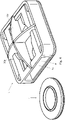
- eine Seitenansicht der Ausführungsform von schräg unten;
- Fig. 4
- einen Montageschritt der Ausführungsform in einer schematischen Seitenansicht;
-
Figuren 1 bis 3 zeigen eine Ausführungsform in zusammengebautem Zustand, mit einem Grundkörper 1, welcher ein Unterteil 5 und eine über Stützen 6 vom Unterteil 5 beabstandete Schutzabdeckung 7 aufweist. Dabei sind zwei Stützen 6 voneinander gegenüberliegend an den Seiten des Unterteils 5 angeordnet, womit sich zwischen Unterteil 5 und Schutzabdeckung 7 ein Kanal 8 mit zwei Einführöffnungen 14 bildet. Die Schutzabdeckung 7 ist oberhalb der Auslassöffnung 2 angeordnet und deckt diese ab. InFig. 1 ist das Sicherheitsventil an einer Gehäusewand 20 eines Batteriegehäuses angeordnet, wobei das Batteriegehäuse zumindest ein Batteriemodul aufweist und im Wesentlichen dicht ist. Der Unterteil 5 weist mittig eine Auslassöffnung 2 auf, welche rund ausgeführt ist. Eine von der Schutzabdeckung 7 abgewandte Verbindungsfläche des Unterteils 5 ist mit der Gehäusewand 20 verbunden, sodass die Auslassöffnung 2 mit einer Öffnung 21 der Gehäusewand 20 strömungsverbunden ist. Die Öffnung 21 der Gehäusewand 20 ist größer als die Auslassöffnung 2, wird jedoch vollständig vom Grundkörper 1 umgrenzt. Die Öffnung 21 kann auch kleiner oder gleich groß in Bezug zur Auslassöffnung 2 sein. - Damit verschließt der Grundkörper 1 abgesehen von der Auslassöffnung 2 die Öffnung 21. Somit steht die Auslassöffnung 2 auch in Strömungsverbindung zu dem Raum 22 jenseits der Gehäusewand 20. Zur Abdichtung mit der Gehäusewand 20 ist an der Verbindungsfläche eine Dichtung 9 vorgesehen. Die Schutzabdeckung 7 weist zwei Hauptbalken 10a auf, welche mehrere Belüftungsöffnungen begrenzen.
- Der Grundkörper 1 weist insgesamt vier elastische Elemente 3 auf, welche mit dem Grundkörper 1 einstückig verbunden sind und gleichmäßig um die Auslassöffnung 2 angeordnet sind. In dieser Ausführungsform sind die elastischen Elemente 3 einstückig mit der Schutzabdeckung 7 über Verbindungsbereiche 3a verbunden. Die elastischen Elemente 3 sind als Blattfedern ausgeführt, welche sich in Richtung der Mitte der Auslassöffnung 2 zuerst im Verbindungsbereich 3a im Wesentlichen parallel zur Auslassöffnung 2 und dann in einem Federbereich 3b in Richtung der Auslassöffnung 2 erstrecken. Darüber hinaus weisen sie Endbereiche 3c auf, welche wieder einen flacheren Winkel zur Auslassöffnung 2 aufweisen, als die Federbereiche 3b. Damit weisen die elastischen Elemente 3 im Schnitt im Wesentlichen eine S-Form auf.
- Zwischen den elastischen Elementen 3 und dem Unterteil 5 ist ein Ventilteil 4 angeordnet, welches durch die elastischen Elemente 3 gegen eine Auflagefläche 10 des Grundkörpers 1, in diesem Fall des Unterteils 5, drückt und damit vorspannt (siehe Pfeile 15). Die Auflagefläche 10 umgrenzt die kreisförmige Auslassöffnung 2 vollständig und der Ventilteil 4 liegt durchgehend um die Auslassöffnung 2 an der Auflagefläche 10 an, womit der Ventilteil 4 die Auslassöffnung 2 vollständig abdeckt. Im Bereich der Berührung zwischen Ventilteil 4 und Auflagefläche 10 ist ein Dichtungselement 11 am Ventilteil 4 vorgesehen. Damit wird die Öffnung der Gehäusewand 20, über der das Sicherheitsventil anordenbar ist, vollständig abgedichtet.
- Der Ventilteil 4 weist einen Hauptkörper 12 mit einer mittig angeordneten Ausnehmung auf, in die eine semipermeable Membran 13 angeordnet ist. Vorzugsweise ist diese Membran 13 in den Hauptkörper eingespritzt. Der Hauptköper 12 weist um die kreisförmige Ausnehmung einen Zentrierring 16 auf, welcher als Festlegeschulter dient und als Erhebung in Bezug zum restlichen Hauptkörper 12 ausgeführt ist. An diesem Zentrierring 16 liegen die elastischen Elemente 3 im zusammengebauten Zustand an, gegebenenfalls mit Spiel, wodurch der Ventilteil 4 von den elastischen Elementen 3 formschlüssig oberhalb der Auslassöffnung 2 gehalten und über diese zentriert wird. Die Endbereiche 3c verhindern das zu starke Verrücken des Ventilteils 4 gegenüber dem Grundkörper 1. Soll der Ventilteil 4 entfernt werden, so müssen zumindest zwei elastische Elemente 3 elastisch angehoben werden und der Ventilteil 4 entlang der Auflagefläche 10 durch den Kanal 8 geschoben werden.
- In
Fig. 3 wird ersichtlich, dass auf der Verbindungsfläche des Grundkörpers 1 vier Aufnahmen 23 für Schrauben (nicht dargestellt) angeordnet sind, welche das Sicherungsventil an einer Gehäusewand 20 festlegen können. Diese sind in den Ecken des Grundkörpers 1 angeordnet, im Bereich der Stützen 6. Dabei können die Schrauben selbstformend ausgeführt sein. Es kann auch nur eine oder eine andere beliebige Anzahl an Schrauben vorgesehen sein. - In
Fig. 4 wird schematisch ein Montageschritt der in den weiteren Figuren gezeigten Ausführungsform gezeigt. Dabei werden der Ventilkörper 4 und der Grundkörper 1 dieser zweiteiligen Ausführungsform zusammengeführt. Dazu wird der Ventilkörper 4 durch eine Einführöffnung 14 in den Grundkörper entlang der Auflagefläche 10 eingeführt. Der Grundkörper 1 ist in Bezug zu einer Mittelebene normal zur Auslassöffnung 2 symmetrisch ausgeführt. Dies hat den Vorteil, dass unwichtig ist, über welche Einführöffnung 14 der Ventilteil 4 eingeführt wird. Dabei werden die elastischen Elemente 3 durch den Ventilkörper 4 elastisch nach oben gebogen, geben damit den Platz für den Ventilkörper 4 frei und spannen ihn vor. Alternativ kann vorgesehen sein, dass die elastischen Elemente 3 zumindest teilweise während des Einführens des Ventilteils 4 von der Auslassöffnung 2 durch den Zusammenbauenden oder ein Werkzeug elastisch weggebogen werden. - Sobald die zwei elastischen Elemente 3, die auf der Seite der verwendeten Einführöffnung 4 liegen, am Rand des Zentrierrings 16 angeordnet sind, schnappen diese nach unten und verhindern die Rückwärtsbewegung des Ventilteils 4. Die übrigen elastischen Elemente verhindern durch Anliegen am Zentrierring 16 das zu weite Verschieben des Ventilteils 4. Durch das Einschnappen ist dem Monteur sofort klar, dass die Zusammenführung abgeschlossen ist.
Claims (13)
- Sicherheitsventil, insbesondere für ein Gehäuse wie ein Batteriegehäuse, mit einem Grundkörper (1), zumindest einem elastischen Element (3) und einem Ventilteil (4), wobei das elastische Element (3) den Ventilteil (4) in eine geschlossene Stellung vorspannt, wobei der Ventilteil (4) in der geschlossenen Stellung an dem Grundkörper (1) anliegt und zumindest eine Auslassöffnung (2) des Grundkörpers (1) verschließt, wobei das elastische Element (3) einstückig mit dem Grundkörper (1) verbunden ist, dadurch gekennzeichnet, dass der Ventilteil (4) zwischen das elastische Element (3) und eine um die Auslassöffnung (2) angeordnete Auflagefläche (10) des Grundkörpers (1) einschiebbar ist.
- Sicherheitsventil nach Anspruch 1, dadurch gekennzeichnet, dass das elastische Element (3) den Ventilteil (4) in der geschlossenen Stellung festlegt.
- Sicherheitsventil nach Anspruch 2, dadurch gekennzeichnet, dass das elastische Element (3) den Ventilteil (4) formschlüssig festlegt.
- Sicherheitsventil nach Anspruch 3, dadurch gekennzeichnet, dass der Ventilteil (4) zumindest eine Festlegeschulter aufweist, an welcher das elastische Element (3) den Ventilteil (4) in der geschlossenen Stellung formschlüssig festlegt.
- Sicherheitsventil nach einem der Ansprüche 1 bis 4, dadurch gekennzeichnet, dass das elastische Element (3) als Blattfeder ausgeführt ist.
- Sicherheitsventil nach einem der Ansprüche 1 bis 5, dadurch gekennzeichnet, dass der Ventilteil (4) zumindest ein Dichtungselement (11) zum Abdichten der Verbindung zwischen dem Ventilteil (4) und dem Grundkörper (1) bei geschlossener Stellung aufweist.
- Sicherheitsventil nach einem der Ansprüche 1 bis 6, dadurch gekennzeichnet, dass der Grundkörper (1) eine Schutzabdeckung (7) im Bereich der Auslassöffnung (2) aufweist und dass der Ventilteil (4) zwischen Schutzabdeckung (7) und Auslassöffnung (2) angeordnet ist.
- Sicherheitsventil nach Anspruch 7, dadurch gekennzeichnet, dass der Grundkörper (1) eine seitlich der Auslassöffnung (2) angeordnete Einführöffnung (14) zum Einführen des Ventilteils (4) aufweist.
- Sicherheitsventil nach einem der Ansprüche 1 bis 8, dadurch gekennzeichnet, dass der Ventilteil (4) einen Hauptkörper (12), vorzugsweise aus Hartkunststoff, aufweist.
- Sicherheitsventil nach Anspruch 9, dadurch gekennzeichnet, dass der Hauptkörper (12) des Ventilteils (4) einen Zentrierring (16) aufweist, an dem das elastische Element (3) zumindest teilweise anliegt und den Ventilteil (4) zentriert.
- Sicherheitsventil nach Anspruch 9 oder 10, dadurch gekennzeichnet, dass das elastische Element (3) auf dem Hauptkörper (12) des Ventilteils (4) anliegt.
- Sicherheitsventil nach einem der Ansprüche 1 bis 11, dadurch gekennzeichnet, dass der Ventilteil (4) eine semipermeable Membran (13) aufweist.
- Sicherheitsventil nach Anspruch 12, dadurch gekennzeichnet, dass die semipermeable Membran (13) von dem Hauptkörper (12) des Ventilteils (4) umschlossen ist.
Applications Claiming Priority (1)
| Application Number | Priority Date | Filing Date | Title |
|---|---|---|---|
| ATA50778/2019A AT522679B1 (de) | 2019-09-05 | 2019-09-05 | Sicherheitsventil |
Publications (2)
| Publication Number | Publication Date |
|---|---|
| EP3789642A1 EP3789642A1 (de) | 2021-03-10 |
| EP3789642B1 true EP3789642B1 (de) | 2022-05-04 |
Family
ID=72322326
Family Applications (1)
| Application Number | Title | Priority Date | Filing Date |
|---|---|---|---|
| EP20193791.9A Active EP3789642B1 (de) | 2019-09-05 | 2020-09-01 | Sicherheitsventil |
Country Status (3)
| Country | Link |
|---|---|
| EP (1) | EP3789642B1 (de) |
| AT (1) | AT522679B1 (de) |
| ES (1) | ES2923687T3 (de) |
Family Cites Families (11)
| Publication number | Priority date | Publication date | Assignee | Title |
|---|---|---|---|---|
| US3257237A (en) * | 1965-03-04 | 1966-06-21 | Accumulatornefabrik Sonnensche | Lead acid type storage battery |
| DE1952449U (de) * | 1966-10-19 | 1966-12-29 | Varta Ag | Ventilverschluss fuer gasdichte akkumulatoren. |
| JPS5066118U (de) * | 1973-10-17 | 1975-06-14 | ||
| JPS522126U (de) * | 1975-06-23 | 1977-01-08 | ||
| DE2537510C3 (de) * | 1975-08-22 | 1979-05-31 | Woco Franz-Josef Wolf & Co, 6483 Bad Soden | Zweiteiliges Oberdruckventil |
| JPH03159058A (ja) * | 1989-11-17 | 1991-07-09 | Seiko Electronic Components Ltd | 調圧ユニット付電池 |
| DE50012351D1 (de) * | 2000-11-29 | 2006-05-04 | Vb Autobatterie Gmbh & Co Kgaa | Verschlussstopfenanordnung für Akkumulatoren |
| DE202004009673U1 (de) | 2004-05-05 | 2005-09-15 | Hengst Gmbh & Co Kg | Ventilanordnung in einer Kurbelgehäuseentlüftung |
| JP5172315B2 (ja) * | 2007-12-18 | 2013-03-27 | プライムアースEvエナジー株式会社 | 二次電池 |
| EP3284985B1 (de) * | 2016-08-17 | 2020-01-08 | W.L. Gore & Associates GmbH | Rückschlagventil |
| CN106356486B (zh) * | 2016-11-29 | 2019-03-29 | 北京新能源汽车股份有限公司 | 一种电池包防爆阀结构、电池包结构及汽车 |
-
2019
- 2019-09-05 AT ATA50778/2019A patent/AT522679B1/de active
-
2020
- 2020-09-01 ES ES20193791T patent/ES2923687T3/es active Active
- 2020-09-01 EP EP20193791.9A patent/EP3789642B1/de active Active
Also Published As
| Publication number | Publication date |
|---|---|
| AT522679B1 (de) | 2021-01-15 |
| ES2923687T3 (es) | 2022-09-29 |
| AT522679A4 (de) | 2021-01-15 |
| EP3789642A1 (de) | 2021-03-10 |
Similar Documents
| Publication | Publication Date | Title |
|---|---|---|
| EP3813186A1 (de) | Ventil zum druckausgleich und/oder zur notentlüftung eines behälters, vorzugsweise eines gehäuses einer batterie von elektrofahrzeugen, sowie behälter mit einem solchen ventil | |
| DE102020130036A1 (de) | Druckentlastungsvorrichtung | |
| EP1711698A1 (de) | Thermostatventilanordnung | |
| WO2022112036A1 (de) | Druckausgleichseinrichtung, verfahren zum druckausgleich und gehäuse, insbesondere batteriegehäuse | |
| DE19751136A1 (de) | Stopfensystem zum Verschließen von Zellenöffnungen eines Akkumulators und Akkumulatordeckel zur Verwendung des Stopfensystems | |
| DE102017123078B4 (de) | Druckausgleichseinheit und Baueinheit aus einem Gehäuse und einer Druckausgleichseinheit | |
| EP3925021A1 (de) | Druckentlastungsventil zum abbau von in einem zellenartigen hohlraum, wie einer batteriezelle, entstehendem druck | |
| DE102020134548A1 (de) | Notentgasungsvorrichtung | |
| DE102021123420A1 (de) | Notentgasungsventil | |
| DE102021131551A1 (de) | Entgasungseinheit für ein Elektronikgehäuse und Elektronikgehäuse mit einer Entgasungseinheit | |
| DE102008001594A1 (de) | Träger mit Druckausgleichsmembran sowie Antriebsvorrichtung, insbesondere für Kraftfahrzeuganwendungen | |
| EP1231421B1 (de) | Dichtungsventilanordnung | |
| EP3789642B1 (de) | Sicherheitsventil | |
| WO2011154339A1 (de) | Wasserablaufventil für elektronikgehäuse und elektronikgehäuse mit einem solchen wasserablaufventil | |
| DE102020130034A1 (de) | Montagesitz für Druckentlastungsvorrichtung | |
| DE102021001258B4 (de) | Ventil zum Druckausgleich und/oder zur Notentlüftung eines Behälters, vorzugsweise eines Gehäuses einer Fahrzeugbatterie, sowie Behälter mit einem solchen Ventil | |
| WO2023072599A1 (de) | Filterlüfter in kastenform mit schraubenloser schnellbefestigungseinrichtung | |
| WO2023030710A1 (de) | Druckausgleichsvorrichtung | |
| EP4592570A1 (de) | Druckausgleichselement für behälter, vorzugsweise für batteriegehäuse von fahrzeugen | |
| DE602004006457T2 (de) | Ventilanordnung | |
| DE102022132645B4 (de) | Druckausgleichsvorrichtung für ein Gehäuse | |
| DE102021003923A1 (de) | Ventil zum Druckausgleich und/oder zur Notentlüftung eines Behälters | |
| WO1999028605A1 (de) | Verschlussdeckel | |
| EP1573241A1 (de) | Entlüfter | |
| EP4374111B1 (de) | Rückstromsperrvorrichtung für einen von einer luftströmung durchströmten strömungskanal |
Legal Events
| Date | Code | Title | Description |
|---|---|---|---|
| PUAI | Public reference made under article 153(3) epc to a published international application that has entered the european phase |
Free format text: ORIGINAL CODE: 0009012 |
|
| STAA | Information on the status of an ep patent application or granted ep patent |
Free format text: STATUS: THE APPLICATION HAS BEEN PUBLISHED |
|
| AK | Designated contracting states |
Kind code of ref document: A1 Designated state(s): AL AT BE BG CH CY CZ DE DK EE ES FI FR GB GR HR HU IE IS IT LI LT LU LV MC MK MT NL NO PL PT RO RS SE SI SK SM TR |
|
| AX | Request for extension of the european patent |
Extension state: BA ME |
|
| STAA | Information on the status of an ep patent application or granted ep patent |
Free format text: STATUS: REQUEST FOR EXAMINATION WAS MADE |
|
| 17P | Request for examination filed |
Effective date: 20210805 |
|
| RBV | Designated contracting states (corrected) |
Designated state(s): AL AT BE BG CH CY CZ DE DK EE ES FI FR GB GR HR HU IE IS IT LI LT LU LV MC MK MT NL NO PL PT RO RS SE SI SK SM TR |
|
| GRAP | Despatch of communication of intention to grant a patent |
Free format text: ORIGINAL CODE: EPIDOSNIGR1 |
|
| STAA | Information on the status of an ep patent application or granted ep patent |
Free format text: STATUS: GRANT OF PATENT IS INTENDED |
|
| INTG | Intention to grant announced |
Effective date: 20220105 |
|
| GRAS | Grant fee paid |
Free format text: ORIGINAL CODE: EPIDOSNIGR3 |
|
| GRAA | (expected) grant |
Free format text: ORIGINAL CODE: 0009210 |
|
| STAA | Information on the status of an ep patent application or granted ep patent |
Free format text: STATUS: THE PATENT HAS BEEN GRANTED |
|
| AK | Designated contracting states |
Kind code of ref document: B1 Designated state(s): AL AT BE BG CH CY CZ DE DK EE ES FI FR GB GR HR HU IE IS IT LI LT LU LV MC MK MT NL NO PL PT RO RS SE SI SK SM TR |
|
| REG | Reference to a national code |
Ref country code: GB Ref legal event code: FG4D Free format text: NOT ENGLISH |
|
| REG | Reference to a national code |
Ref country code: CH Ref legal event code: EP |
|
| REG | Reference to a national code |
Ref country code: AT Ref legal event code: REF Ref document number: 1489375 Country of ref document: AT Kind code of ref document: T Effective date: 20220515 |
|
| REG | Reference to a national code |
Ref country code: IE Ref legal event code: FG4D Free format text: LANGUAGE OF EP DOCUMENT: GERMAN Ref country code: DE Ref legal event code: R096 Ref document number: 502020001055 Country of ref document: DE |
|
| REG | Reference to a national code |
Ref country code: LT Ref legal event code: MG9D |
|
| REG | Reference to a national code |
Ref country code: NL Ref legal event code: MP Effective date: 20220504 |
|
| REG | Reference to a national code |
Ref country code: ES Ref legal event code: FG2A Ref document number: 2923687 Country of ref document: ES Kind code of ref document: T3 Effective date: 20220929 |
|
| PG25 | Lapsed in a contracting state [announced via postgrant information from national office to epo] |
Ref country code: SE Free format text: LAPSE BECAUSE OF FAILURE TO SUBMIT A TRANSLATION OF THE DESCRIPTION OR TO PAY THE FEE WITHIN THE PRESCRIBED TIME-LIMIT Effective date: 20220504 Ref country code: PT Free format text: LAPSE BECAUSE OF FAILURE TO SUBMIT A TRANSLATION OF THE DESCRIPTION OR TO PAY THE FEE WITHIN THE PRESCRIBED TIME-LIMIT Effective date: 20220905 Ref country code: NO Free format text: LAPSE BECAUSE OF FAILURE TO SUBMIT A TRANSLATION OF THE DESCRIPTION OR TO PAY THE FEE WITHIN THE PRESCRIBED TIME-LIMIT Effective date: 20220804 Ref country code: NL Free format text: LAPSE BECAUSE OF FAILURE TO SUBMIT A TRANSLATION OF THE DESCRIPTION OR TO PAY THE FEE WITHIN THE PRESCRIBED TIME-LIMIT Effective date: 20220504 Ref country code: LT Free format text: LAPSE BECAUSE OF FAILURE TO SUBMIT A TRANSLATION OF THE DESCRIPTION OR TO PAY THE FEE WITHIN THE PRESCRIBED TIME-LIMIT Effective date: 20220504 Ref country code: HR Free format text: LAPSE BECAUSE OF FAILURE TO SUBMIT A TRANSLATION OF THE DESCRIPTION OR TO PAY THE FEE WITHIN THE PRESCRIBED TIME-LIMIT Effective date: 20220504 Ref country code: GR Free format text: LAPSE BECAUSE OF FAILURE TO SUBMIT A TRANSLATION OF THE DESCRIPTION OR TO PAY THE FEE WITHIN THE PRESCRIBED TIME-LIMIT Effective date: 20220805 Ref country code: FI Free format text: LAPSE BECAUSE OF FAILURE TO SUBMIT A TRANSLATION OF THE DESCRIPTION OR TO PAY THE FEE WITHIN THE PRESCRIBED TIME-LIMIT Effective date: 20220504 Ref country code: BG Free format text: LAPSE BECAUSE OF FAILURE TO SUBMIT A TRANSLATION OF THE DESCRIPTION OR TO PAY THE FEE WITHIN THE PRESCRIBED TIME-LIMIT Effective date: 20220804 |
|
| PG25 | Lapsed in a contracting state [announced via postgrant information from national office to epo] |
Ref country code: RS Free format text: LAPSE BECAUSE OF FAILURE TO SUBMIT A TRANSLATION OF THE DESCRIPTION OR TO PAY THE FEE WITHIN THE PRESCRIBED TIME-LIMIT Effective date: 20220504 Ref country code: PL Free format text: LAPSE BECAUSE OF FAILURE TO SUBMIT A TRANSLATION OF THE DESCRIPTION OR TO PAY THE FEE WITHIN THE PRESCRIBED TIME-LIMIT Effective date: 20220504 Ref country code: LV Free format text: LAPSE BECAUSE OF FAILURE TO SUBMIT A TRANSLATION OF THE DESCRIPTION OR TO PAY THE FEE WITHIN THE PRESCRIBED TIME-LIMIT Effective date: 20220504 Ref country code: IS Free format text: LAPSE BECAUSE OF FAILURE TO SUBMIT A TRANSLATION OF THE DESCRIPTION OR TO PAY THE FEE WITHIN THE PRESCRIBED TIME-LIMIT Effective date: 20220904 |
|
| PG25 | Lapsed in a contracting state [announced via postgrant information from national office to epo] |
Ref country code: SM Free format text: LAPSE BECAUSE OF FAILURE TO SUBMIT A TRANSLATION OF THE DESCRIPTION OR TO PAY THE FEE WITHIN THE PRESCRIBED TIME-LIMIT Effective date: 20220504 Ref country code: SK Free format text: LAPSE BECAUSE OF FAILURE TO SUBMIT A TRANSLATION OF THE DESCRIPTION OR TO PAY THE FEE WITHIN THE PRESCRIBED TIME-LIMIT Effective date: 20220504 Ref country code: RO Free format text: LAPSE BECAUSE OF FAILURE TO SUBMIT A TRANSLATION OF THE DESCRIPTION OR TO PAY THE FEE WITHIN THE PRESCRIBED TIME-LIMIT Effective date: 20220504 Ref country code: EE Free format text: LAPSE BECAUSE OF FAILURE TO SUBMIT A TRANSLATION OF THE DESCRIPTION OR TO PAY THE FEE WITHIN THE PRESCRIBED TIME-LIMIT Effective date: 20220504 Ref country code: DK Free format text: LAPSE BECAUSE OF FAILURE TO SUBMIT A TRANSLATION OF THE DESCRIPTION OR TO PAY THE FEE WITHIN THE PRESCRIBED TIME-LIMIT Effective date: 20220504 Ref country code: CZ Free format text: LAPSE BECAUSE OF FAILURE TO SUBMIT A TRANSLATION OF THE DESCRIPTION OR TO PAY THE FEE WITHIN THE PRESCRIBED TIME-LIMIT Effective date: 20220504 |
|
| REG | Reference to a national code |
Ref country code: DE Ref legal event code: R097 Ref document number: 502020001055 Country of ref document: DE |
|
| PLBE | No opposition filed within time limit |
Free format text: ORIGINAL CODE: 0009261 |
|
| STAA | Information on the status of an ep patent application or granted ep patent |
Free format text: STATUS: NO OPPOSITION FILED WITHIN TIME LIMIT |
|
| PG25 | Lapsed in a contracting state [announced via postgrant information from national office to epo] |
Ref country code: AL Free format text: LAPSE BECAUSE OF FAILURE TO SUBMIT A TRANSLATION OF THE DESCRIPTION OR TO PAY THE FEE WITHIN THE PRESCRIBED TIME-LIMIT Effective date: 20220504 |
|
| 26N | No opposition filed |
Effective date: 20230207 |
|
| PG25 | Lapsed in a contracting state [announced via postgrant information from national office to epo] |
Ref country code: MC Free format text: LAPSE BECAUSE OF FAILURE TO SUBMIT A TRANSLATION OF THE DESCRIPTION OR TO PAY THE FEE WITHIN THE PRESCRIBED TIME-LIMIT Effective date: 20220504 |
|
| REG | Reference to a national code |
Ref country code: BE Ref legal event code: MM Effective date: 20220930 |
|
| PG25 | Lapsed in a contracting state [announced via postgrant information from national office to epo] |
Ref country code: SI Free format text: LAPSE BECAUSE OF FAILURE TO SUBMIT A TRANSLATION OF THE DESCRIPTION OR TO PAY THE FEE WITHIN THE PRESCRIBED TIME-LIMIT Effective date: 20220504 |
|
| P01 | Opt-out of the competence of the unified patent court (upc) registered |
Effective date: 20230508 |
|
| PG25 | Lapsed in a contracting state [announced via postgrant information from national office to epo] |
Ref country code: LU Free format text: LAPSE BECAUSE OF NON-PAYMENT OF DUE FEES Effective date: 20220901 |
|
| PG25 | Lapsed in a contracting state [announced via postgrant information from national office to epo] |
Ref country code: IE Free format text: LAPSE BECAUSE OF NON-PAYMENT OF DUE FEES Effective date: 20220901 |
|
| PG25 | Lapsed in a contracting state [announced via postgrant information from national office to epo] |
Ref country code: BE Free format text: LAPSE BECAUSE OF NON-PAYMENT OF DUE FEES Effective date: 20220930 |
|
| PG25 | Lapsed in a contracting state [announced via postgrant information from national office to epo] |
Ref country code: CY Free format text: LAPSE BECAUSE OF FAILURE TO SUBMIT A TRANSLATION OF THE DESCRIPTION OR TO PAY THE FEE WITHIN THE PRESCRIBED TIME-LIMIT Effective date: 20220504 |
|
| REG | Reference to a national code |
Ref country code: CH Ref legal event code: PL |
|
| PG25 | Lapsed in a contracting state [announced via postgrant information from national office to epo] |
Ref country code: MK Free format text: LAPSE BECAUSE OF FAILURE TO SUBMIT A TRANSLATION OF THE DESCRIPTION OR TO PAY THE FEE WITHIN THE PRESCRIBED TIME-LIMIT Effective date: 20220504 Ref country code: HU Free format text: LAPSE BECAUSE OF FAILURE TO SUBMIT A TRANSLATION OF THE DESCRIPTION OR TO PAY THE FEE WITHIN THE PRESCRIBED TIME-LIMIT; INVALID AB INITIO Effective date: 20200901 |
|
| PG25 | Lapsed in a contracting state [announced via postgrant information from national office to epo] |
Ref country code: TR Free format text: LAPSE BECAUSE OF FAILURE TO SUBMIT A TRANSLATION OF THE DESCRIPTION OR TO PAY THE FEE WITHIN THE PRESCRIBED TIME-LIMIT Effective date: 20220504 |
|
| PG25 | Lapsed in a contracting state [announced via postgrant information from national office to epo] |
Ref country code: CH Free format text: LAPSE BECAUSE OF NON-PAYMENT OF DUE FEES Effective date: 20230930 |
|
| PG25 | Lapsed in a contracting state [announced via postgrant information from national office to epo] |
Ref country code: CH Free format text: LAPSE BECAUSE OF NON-PAYMENT OF DUE FEES Effective date: 20230930 |
|
| PG25 | Lapsed in a contracting state [announced via postgrant information from national office to epo] |
Ref country code: MT Free format text: LAPSE BECAUSE OF FAILURE TO SUBMIT A TRANSLATION OF THE DESCRIPTION OR TO PAY THE FEE WITHIN THE PRESCRIBED TIME-LIMIT Effective date: 20220504 |
|
| PGFP | Annual fee paid to national office [announced via postgrant information from national office to epo] |
Ref country code: DE Payment date: 20240926 Year of fee payment: 5 |
|
| PGFP | Annual fee paid to national office [announced via postgrant information from national office to epo] |
Ref country code: GB Payment date: 20240924 Year of fee payment: 5 |
|
| PGFP | Annual fee paid to national office [announced via postgrant information from national office to epo] |
Ref country code: FR Payment date: 20240925 Year of fee payment: 5 |
|
| PGFP | Annual fee paid to national office [announced via postgrant information from national office to epo] |
Ref country code: IT Payment date: 20240924 Year of fee payment: 5 |
|
| PG25 | Lapsed in a contracting state [announced via postgrant information from national office to epo] |
Ref country code: BG Free format text: LAPSE BECAUSE OF FAILURE TO SUBMIT A TRANSLATION OF THE DESCRIPTION OR TO PAY THE FEE WITHIN THE PRESCRIBED TIME-LIMIT Effective date: 20220504 |
|
| PG25 | Lapsed in a contracting state [announced via postgrant information from national office to epo] |
Ref country code: BG Free format text: LAPSE BECAUSE OF FAILURE TO SUBMIT A TRANSLATION OF THE DESCRIPTION OR TO PAY THE FEE WITHIN THE PRESCRIBED TIME-LIMIT Effective date: 20220504 |
|
| PGFP | Annual fee paid to national office [announced via postgrant information from national office to epo] |
Ref country code: ES Payment date: 20241021 Year of fee payment: 5 |
|
| PGFP | Annual fee paid to national office [announced via postgrant information from national office to epo] |
Ref country code: AT Payment date: 20251020 Year of fee payment: 5 |