EP3789636B1 - Gear transmission - Google Patents
Gear transmission Download PDFInfo
- Publication number
- EP3789636B1 EP3789636B1 EP20193575.6A EP20193575A EP3789636B1 EP 3789636 B1 EP3789636 B1 EP 3789636B1 EP 20193575 A EP20193575 A EP 20193575A EP 3789636 B1 EP3789636 B1 EP 3789636B1
- Authority
- EP
- European Patent Office
- Prior art keywords
- gear
- drive
- wheel
- range
- teeth
- Prior art date
- Legal status (The legal status is an assumption and is not a legal conclusion. Google has not performed a legal analysis and makes no representation as to the accuracy of the status listed.)
- Active
Links
- 230000005540 biological transmission Effects 0.000 title claims description 10
- 230000013011 mating Effects 0.000 description 15
- 230000009467 reduction Effects 0.000 description 5
- 238000005516 engineering process Methods 0.000 description 3
- 238000010276 construction Methods 0.000 description 1
- 238000006073 displacement reaction Methods 0.000 description 1
Images


Classifications
-
- F—MECHANICAL ENGINEERING; LIGHTING; HEATING; WEAPONS; BLASTING
- F16—ENGINEERING ELEMENTS AND UNITS; GENERAL MEASURES FOR PRODUCING AND MAINTAINING EFFECTIVE FUNCTIONING OF MACHINES OR INSTALLATIONS; THERMAL INSULATION IN GENERAL
- F16H—GEARING
- F16H55/00—Elements with teeth or friction surfaces for conveying motion; Worms, pulleys or sheaves for gearing mechanisms
- F16H55/02—Toothed members; Worms
- F16H55/08—Profiling
- F16H55/0806—Involute profile
-
- F—MECHANICAL ENGINEERING; LIGHTING; HEATING; WEAPONS; BLASTING
- F16—ENGINEERING ELEMENTS AND UNITS; GENERAL MEASURES FOR PRODUCING AND MAINTAINING EFFECTIVE FUNCTIONING OF MACHINES OR INSTALLATIONS; THERMAL INSULATION IN GENERAL
- F16H—GEARING
- F16H1/00—Toothed gearings for conveying rotary motion
- F16H1/02—Toothed gearings for conveying rotary motion without gears having orbital motion
- F16H1/04—Toothed gearings for conveying rotary motion without gears having orbital motion involving only two intermeshing members
Definitions
- gear drives are often used, which produce the highest possible speed reduction ratio and thus a high torque, but at the same time must be able to be turned back easily from the output side.
- the ability to rotate back is required, for example, in order to be able to manually operate electrically operated flaps on an automobile or windows on a building in the event of a power failure.
- the gear drive is a spindle drive for motorized adjustment of an adjustment element of a motor vehicle, for example as a tailgate drive.
- this is designed to be non-self-locking in order to ensure manual adjustability to allow the tailgate.
- the gear geometry reference is made to the state of the art on evoloid gears, namely " Gear technology, involute special gears for gear improvement", Dr.-Ing. Karlheinz Roth, Springer-Verlag Berlin Heidelberg, 1998, ISBN 3-540-642 36-6, Chapter 1 "Evoloid gears ", page 2 ff .
- an actuator for motor vehicle locking devices which has an electric motor and an actuating element acted upon by the electric motor via a drive train.
- Evoloid gearing is provided in the drive train.
- a drive shaft of the electric motor is equipped with an evoloid pinion, which meshes with an evoloid output wheel, directly realizing the evoloid gearing.
- the evoloid pinion preferably has three teeth. However, only a single tooth is conceivable. Furthermore, it is pointed out that such evoloid toothings are generally not designed to be self-locking.
- the center distance of the gear drive is divided into two distances in relation to the transmission ratio. These sections are the radii of the pitch circles.
- the decisive parameters of the tooth of the drive wheel are the root height factor hfP in a range from 0.2 to 0.4, the addendum height factor h aP in a range from 0.6 to 0.8 and the root radius factor QfP in a range from 0 .1 to 0.4.
- Compliance with the foot radius factor is an essential criterion for easy reverse rotation.
- the range information includes the range limits.
- Crucial characteristics of the teeth of the mating gear for the ability to rotate back are the root height factor h fP in a range from 0.8 to 1.2, a tip height factor h aP in a range from 0.1 to 0.5 and a root radius factor in a range from 0.3 to 0.8. Compliance with the foot radius factor is an essential criterion for easy reverse rotation.
- the range information includes the range limits.
- the profile contact ratio ⁇ ⁇ due to the inclined position of the line of action is supplemented by a proportion of the step contact ratio ⁇ ⁇ over the tooth width.
- the total overlap ⁇ ⁇ of the drive and counter gears must be greater than 1.3 in order to ensure easy reverse rotation, with the total overlap ⁇ ⁇ being the sum of the profile overlap ⁇ ⁇ and the jump overlap ⁇ ⁇ of the drive and counter gears.
- the root diameter is close to the pitch circle, it is approximately tangent to the pitch circle.
- the drive wheel and the mating wheel can be components of a wide variety of gear designs, in particular a spur gear, an internal spur gear, a helical gear, a crown gear, a bevel gear, a planetary gear or a rack and pinion gear.
- All of the aforementioned gear designs can be rotated backwards from the drive wheel, i.e. the mating wheel with a larger number of teeth.
- the number of teeth on the counter gear is ⁇ 3, preferably ⁇ 8, in order to ensure a sufficiently high gear reduction to slow.
- gear drives according to the invention are particularly quiet, since the load changes generate low-frequency noises, for which the threshold of audibility is significantly higher than for high frequencies.
- a counter wheel (2) only partially shown, with 30 teeth (3) meshes with the drive wheel (1).
- the toothing parameters of the drive wheel (1) and counter-wheel (2) of the three gear drives l are in the ranges defined in claim 1.
- the total overlap ⁇ ⁇ of the drive and mating gear is greater than 1.3.
- a counter wheel (2) only partially shown, with 10 teeth meshes with the drive wheel (1).
- the toothing parameters of the drive wheel (1) and counter-wheel (2) of the three gear drives l are in the areas defined in claim 4.
- the total overlap ⁇ ⁇ of the drive and mating gear (1), (2) is greater than 1.0 and less than or equal to 1.1, with the total overlap ⁇ ⁇ being the sum of the profile overlap ⁇ ⁇ and the jump overlap ⁇ ⁇ of drive and mating gear and the profile overlap ⁇ ⁇ is greater than or equal to 0.4.
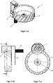
- figure 2 shows a single-stage spur gear (7) designed according to the invention in a perspective view a), in a side view b) and in a sectional view c) along the line CC.
- FIG 3 shows in a side view a) and in a sectional view b) along the line BB figure 3 a) a single-stage internal spur gear (11) designed according to the invention.
- FIG 4 shows in a top view a), a sectional view b) along the line HH figure 4 a) and a perspective view of c) a helical gear (12) designed according to the invention.
- FIG 5 shows in a top view a), a sectional view b) along the line KK figure 5 a) and a perspective view c) a crown gear (13) designed according to the invention.
- the crown gear (13) is an angular gear.
- the counter gear (2) designed as a crown gear, sits on a second shaft (10) running at right angles to the first shaft (9).
- the angle and offset between the first and second shaft (9.10) in the execution vary as crown gears so that the waves intersect or cross.
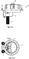
- FIG 6 shows in a top view a), a sectional view b) along the line JJ figure 6 a) and a perspective view c) a bevel gear (14) designed according to the invention.
- the bevel gear (14) is an angular gear whose input and output shafts, which are at an angle to one another, have a common point of intersection.
- the mating gear (2) designed as a helical bevel gear, sits on a second shaft (10) running at right angles to the first shaft (9). Other angles between the shafts (9,10) are possible.
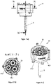
- figure 7 shows in a side view a), a sectional view b) along the line NN figure 7 a) and a perspective view c) a planetary gear (15) designed according to the invention.
- the drive wheel (1) sits on a first shaft (9).
- the output of the planetary gear takes place via the web carrying the counter gears (2).
- FIG 8 shows a top view a) and a perspective view b) of a rack and pinion gear (19) designed according to the invention.
- the geometry of the toothed rack corresponds to the developed geometry of a gear wheel. For this reason, a rack and pinion gear is also regarded as a toothed gear within the meaning of the invention.
Landscapes
- Engineering & Computer Science (AREA)
- General Engineering & Computer Science (AREA)
- Mechanical Engineering (AREA)
- Gear Transmission (AREA)
- Gears, Cams (AREA)
Description
Die Erfindung betrifft ein Zahnradgetriebe mit einer Übersetzung ins Langsame umfassend ein Antriebsrad mit einer Außenverzahnung mit der Zähnezahl Z = 1, das mit einem Gegenrad kämmt.The invention relates to a gear transmission with a step-down ratio, comprising a drive wheel with external teeth with the number of teeth Z=1, which meshes with a counter wheel.
In der Aktorik, z.B. der Gebäudetechnik, der Medizintechnik und dem Automobilbau, werden oft Zahnradgetriebe verwendet, die eine möglichst hohe Übersetzung ins Langsame und damit ein großes Drehmoment erzeugen, aber gleichzeitig von der Abtriebsseite leicht rückdrehbar sein müssen. Die Rückdrehbarkeit ist beispielsweise erforderlich, um elektrisch betätigte Klappen an einem Automobil oder Fenster an einem Gebäude bei einem Stromausfall notfalls von Hand betätigen zu können.In actuators, e.g. in building technology, medical technology and automotive engineering, gear drives are often used, which produce the highest possible speed reduction ratio and thus a high torque, but at the same time must be able to be turned back easily from the output side. The ability to rotate back is required, for example, in order to be able to manually operate electrically operated flaps on an automobile or windows on a building in the event of a power failure.
Die
Aus der
Aus Roth "Evolventen Sonderverzahnungen" und Krause "Konstruktionselemente der Feinmechanik", Seite 576 sind Zahnradgetriebe mit einem Antriebsrad mit der Zähnezahl Z = 1 bekannt, die mit einem Gegenrad kämmen. Die aus dem Stand der Technik bekannten Zahnradgetriebe mit der Zähnezahl Z = 1 sind sämtlich für Übersetzungen in das Langsame ausgelegt. Die aus dem Stand der Technik bekannten Zahnradgetriebe mit der Zähnezahl Z = 1 sind jedoch nicht einwandfrei rückdrehbar.From Roth "Involute Special Gears" and Krause "Construction Elements of Precision Mechanics", page 576, gear drives with a drive wheel with the number of teeth Z=1 are known, which mesh with a mating wheel. The gear drives known from the prior art with the number of teeth Z=1 are all designed for gear reductions. However, the toothed gears known from the prior art with the number of teeth Z=1 cannot be reversely rotated properly.
Ausgehend von diesem Stand der Technik liegt der Erfindung die Aufgabe zu Grunde, ein Zahnradgetriebe mit einer Übersetzung ins Langsame umfassend ein Antriebsrad mit einer Außenverzahnung mit der Zähnezahl Z = 1 zu schaffen, welches von der Abtriebsseite einwandfrei rückdrehbar ist.Proceeding from this state of the art, the invention is based on the object of creating a gear transmission with a step-down ratio comprising a drive wheel with external teeth with the number of teeth Z=1, which can be turned back properly from the output side.
Ein von der Abtriebsseite einwandfrei rückdrehbares Zahnradgetriebe mit einem Antriebsrad mit einer Außenverzahnung mit der Zähnezahl Z=1 und einem abtriebsseitigen Gegenrad mit einer Zähnezahl von Z ≥1 ergibt sich aus den Merkmalen des unabhängigen Anspruchs 1.A gear drive that can be rotated properly from the output side and has a drive wheel with external teeth with the number of teeth Z=1 and a counter gear on the output side with a number of teeth Z ≥1 results from the features of
Der Achsabstand des Zahnradgetriebes wird im Verhältnis des Übersetzungsverhältnisses in zwei Strecken aufgeteilt. Diese Teilstrecken sind die Radien der Wälzkreise. Indem erfindungsgemäß die Zahnhöhe des Gegenrades zum Antriebsrad mit Z=1 unter den Wälzkreis des Gegenrades gelegt wird, kann das Zahnradgetriebe weitgehend unabhängig von der Größe des Eingriffswinkels gut rückdrehbar gestaltet werden.The center distance of the gear drive is divided into two distances in relation to the transmission ratio. These sections are the radii of the pitch circles. By according to the invention the tooth height of the mating gear relative to the drive gear with Z=1 being placed under the pitch circle of the mating gear, the gear train can be designed to be easily reverse-rotatable largely independently of the size of the pressure angle.
Für die Rückdrehbarkeit sind entscheidende Kenngrößen des Zahnes des Antriebsrades der Fußhöhenfaktor hfP in einem Bereich von 0,2 bis 0,4, der Kopfhöhenfaktor haP in einem Bereich von 0,6 bis 0,8 und der Fußradiusfaktor QfP in einem Bereich von 0,1 bis 0,4. Die Einhaltung des Fußradiusfaktors ist für eine leichte Rückdrehung ein wesentliches Kriterium. Die Bereichsangaben schließen jeweils die Bereichsgrenzen mit ein.For the ability to rotate back, the decisive parameters of the tooth of the drive wheel are the root height factor hfP in a range from 0.2 to 0.4, the addendum height factor h aP in a range from 0.6 to 0.8 and the root radius factor QfP in a range from 0 .1 to 0.4. Compliance with the foot radius factor is an essential criterion for easy reverse rotation. The range information includes the range limits.
Für die Rückdrehbarkeit sind entscheidende Kenngrößen der Zähne des Gegenrades der Fußhöhenfaktor hfP in einem Bereich von 0,8 bis 1,2, einen Kopfhöhenfaktor haP in einem Bereich von 0,1 bis 0,5 und einen Fußradiusfaktor
![]()
![]()
Bei der Verzahnung zwischen Antriebsrad mit Z=1 und Gegenrad mit z≥1 kommt zu der Profilüberdeckung εα infolge der Schräglage der Eingriffslinie ein Anteil aus der Sprungüberdeckung εβ über die Zahnbreite hinzu. Die Gesamtüberdeckung εγ von Antriebs- und Gegenrad ist zwingend größer 1,3, um die leichte Rückdrehbarkeit zu gewährleisten, wobei die Gesamtüberdeckung εγ die Summe aus der Profilüberdeckung εα und der Sprungüberdeckung εβ von Antriebs- und Gegenrad ist.In the case of the toothing between the drive wheel with Z=1 and the mating wheel with z≥1, the profile contact ratio ε α due to the inclined position of the line of action is supplemented by a proportion of the step contact ratio ε β over the tooth width. The total overlap ε γ of the drive and counter gears must be greater than 1.3 in order to ensure easy reverse rotation, with the total overlap ε γ being the sum of the profile overlap ε α and the jump overlap ε β of the drive and counter gears.
Das Antriebsrad mit Z=1 hat innen einen Innenzylinder und die Evolvente liegt außerhalb dieses Innenzylinders mit einem großen Hebelarm im Verhältnis zum Zahnkopf des Gegenrades, der eine gute Rückdrehung des Antriebsrad Z=1 vom Gegenzahnrad aus erlaubt. Der Innenzylinder ist umso größer im Durchmesser, je kleiner der Fußhöhenfaktor ist. Der Fußkreisdurchmesser liegt in der Nähe des Wälzkreises, er tangiert ungefähr den Wälzkreis.The drive wheel with Z=1 has an inner cylinder inside and the involute is outside this inner cylinder with a large lever arm in relation to the tooth tip of the counter gear, which allows a good reverse rotation of the drive wheel Z=1 from the counter gear. The smaller the base height factor, the larger the diameter of the inner cylinder. The root diameter is close to the pitch circle, it is approximately tangent to the pitch circle.
Das Antriebsrad und das Gegenrad können Bestandteile verschiedenster Getriebebauformen sein, insbesondere eines Stirnradgetriebes, eines Innenstirnradgetriebes, eines Schraubenradgetriebes, eines Kronenradgetriebes, eines Kegelradgetriebes, eines Planetengetriebes oder eines Zahnstangengetriebes.The drive wheel and the mating wheel can be components of a wide variety of gear designs, in particular a spur gear, an internal spur gear, a helical gear, a crown gear, a bevel gear, a planetary gear or a rack and pinion gear.
Sämtliche vorgenannten Getriebebauformen sind vom Antriebsrad, also dem Gegenrad mit größerer Zähnezahl, rückdrehbar.All of the aforementioned gear designs can be rotated backwards from the drive wheel, i.e. the mating wheel with a larger number of teeth.
Die Zähnezahl des Gegenrades ist ≥ 3, vorzugsweise ≥ 8, um eine hinreichend hohe Untersetzung in das Langsame zu gewährleisten.The number of teeth on the counter gear is ≥3, preferably ≥8, in order to ensure a sufficiently high gear reduction to slow.
Des Weiteren hat sich gezeigt, dass die erfindungsgemäßen Zahnradgetriebe besonders geräuscharm sind, da die Lastwechsel niederfrequente Geräusche erzeugen, bei denen die Hörbarkeitsschwelle deutlich höher als bei hohen Frequenzen liegt.Furthermore, it has been shown that the gear drives according to the invention are particularly quiet, since the load changes generate low-frequency noises, for which the threshold of audibility is significantly higher than for high frequencies.
Nachfolgend wird die Erfindung anhand der Figuren näher erläutert:
- Figur 1a)
- zeigt drei erfindungsgemäße vom Gegenrad aus rückdrehbare Zahnradgetriebe,
- Figur 1b)
- zeigt zwei nicht zur Erfindung gehörige selbsthemmende Zahnradgetriebe,
Figur 2- zeigt ein erfindungsgemäß ausgeführtes Zahnradgetriebe, nämlich ein Stirnradgetriebe
Figur 3- zeigt ein erfindungsgemäß ausgeführtes Zahnradgetriebe, nämlich ein Innenstirnradgetriebe,
Figur 4- zeigt ein erfindungsgemäß ausgeführtes Zahnradgetriebe, nämlich ein Schraubenradgetriebe,
Figur 5- zeigt ein erfindungsgemäß ausgeführtes Zahnradgetriebe, nämlich ein Kronenradgetriebe,
Figur 6- zeigt ein erfindungsgemäß ausgeführtes Zahnradgetriebe, nämlich ein Kegelradgetriebe,
Figur 7- zeigt ein erfindungsgemäß ausgeführtes Zahnradgetriebe, nämlich ein Planetengetriebe und
Figur 8- zeigt ein erfindungsgemäß ausgeführtes Zahnradgetriebe, nämlich ein Zahnstangengetriebe.
- Figure 1a)
- shows three gear drives according to the invention that can be rotated backwards from the counter wheel,
- Figure 1b)
- shows two self-locking gear drives not belonging to the invention,
- figure 2
- shows a gear train designed according to the invention, namely a spur gear train
- figure 3
- shows a gear drive designed according to the invention, namely an internal spur gear drive,
- figure 4
- shows a gear train designed according to the invention, namely a helical gear train,
- figure 5
- shows a gear drive designed according to the invention, namely a crown gear,
- figure 6
- shows a gear train designed according to the invention, namely a bevel gear train,
- figure 7
- shows a gear transmission designed according to the invention, namely a planetary gear and
- figure 8
- shows a gear drive designed according to the invention, namely a rack and pinion drive.
Unterschiede zwischen den drei dargestellten Zahnradgetrieben ergeben sich hinsichtlich des Eingriffswinkels α von 10°, 20° und 45°, der dem Winkel zwischen der Verbindungsnormalen der beiden Zahnradachsen und der Eingriffslinie (4) entspricht. Aus
Die Gesamtüberdeckung εγ von Antriebs- und Gegenrad (1), (2) ist größer als 1,0 und kleiner oder gleich 1,1, wobei die Gesamtüberdeckung εγ die Summe aus der Profilüberdeckung εα und der Sprungüberdeckung εβ von Antriebs- und Gegenrad ist und die Profilüberdeckung εα größer oder gleich 0,4 ist.The total overlap ε γ of the drive and mating gear (1), (2) is greater than 1.0 and less than or equal to 1.1, with the total overlap ε γ being the sum of the profile overlap ε α and the jump overlap ε β of drive and mating gear and the profile overlap ε α is greater than or equal to 0.4.
Unterschiede zwischen den beiden dargestellten, selbsthemmenden Zahnradgetrieben ergeben sich hinsichtlich des Eingriffswinkels α von 10° und 45°, der dem Winkel zwischen der Verbindungsnormalen der beiden Zahnradachsen und der Eingriffslinie (4) entspricht. Aus
In dem Gehäuse (8) sitzt auf einer zweiten, zur ersten Welle (9) parallelen Welle (10) das außen schrägverzahnte Gegenrad (2) mit Z=20.In the housing (8) sits on a second shaft (10) parallel to the first shaft (9) the externally helical mating gear (2) with Z=20.
Sämtliche anhand der
- 1 Antriebsrad1 drive wheel
- 2 Gegenrad2 counter wheel
- 3 Zahn3 tooth
- 4 Eingriffslinie4 line of action
- 5 Zahnhöhe5 tooth height
- 6 Wälzkreis6 pitch circle
- 7 Stirnradgetriebe7 spur gears
- 8 Gehäuse8 housing
- 9 erste Welle9 first wave
- 10 zweite Welle10 second wave
- 11 Innenstirnradgetriebe11 internal spur gears
- 12 Schraubenradgetriebe12 helical gears
- 13 Kronenradgetriebe13 crown gears
- 14 Kegelradgetriebe14 bevel gears
- 15 Planetengetriebe15 planetary gears
- 16 Hohlrad16 ring gear
- 17 Planetenrad17 planet wheel
- 18 Sonnenrad18 sun gear
- 19 Zahnstangengetriebe19 rack and pinion gears
- 20 Zahnstange20 rack
Claims (4)
- A gear transmission with a speed-reducing ratio comprising- a drive wheel (1) having an external toothing with the tooth number Z = 1, wherein the tooth of the drive wheel (1) has a- foot height factor hfP in a range from 0.2 to 0.4,- a head height factor haP in a range from 0.6 to 0.8 and- a foot radius factor QfP in a range from 0.1 to 0.4,- a counter wheel (2) engaging with the drive wheel (1) having a tooth number Z ≥ 1, where the tooth height (5) of the teeth (3) of the counter wheel (2) lies below its pitch circle (6) and the teeth (3) of the counter wheel (2) have a- foot height factor hfP in a range from 0.8 to 1.2,- a head height factor haP in a range from 0.1 to 0.5 and- a foot radius factor QfP in a range from 0.3 to 0.8,- a total contact ratio εγ of drive and counter wheel (1, 2) greater than 1.3.
- The gear transmission with a speed-reducing ratio according to Claim 1, characterized in that the total contact ratio εγ is the sum of the transverse contact εα and the overlap ratio εβ of drive and counter wheel (1, 2).
- The gear transmission according to Claim 1 or 2, characterized in that the drive wheel (1) and the counter wheel (2) are parts of a spur gear (7) or an internal spur gear (11) or a worm wheel gear (12) or a crown gearhead (13) or a bevel gear (14) or a planetary gear (15) or a rack and pinion gear (19).
- The gear transmission according to one of Claims 1 to 3, characterized in that the tooth number of the counter wheel is ≥3, preferably ≥8.
Applications Claiming Priority (1)
| Application Number | Priority Date | Filing Date | Title |
|---|---|---|---|
| DE102019124027 | 2019-09-07 |
Publications (3)
| Publication Number | Publication Date |
|---|---|
| EP3789636A2 EP3789636A2 (en) | 2021-03-10 |
| EP3789636A3 EP3789636A3 (en) | 2021-04-07 |
| EP3789636B1 true EP3789636B1 (en) | 2022-11-23 |
Family
ID=72292335
Family Applications (1)
| Application Number | Title | Priority Date | Filing Date |
|---|---|---|---|
| EP20193575.6A Active EP3789636B1 (en) | 2019-09-07 | 2020-08-31 | Gear transmission |
Country Status (1)
| Country | Link |
|---|---|
| EP (1) | EP3789636B1 (en) |
Family Cites Families (3)
| Publication number | Priority date | Publication date | Assignee | Title |
|---|---|---|---|---|
| DE1200628C2 (en) * | 1961-09-12 | 1966-03-31 | Siemens Ag | Involute gear pairing |
| DE202011106149U1 (en) * | 2011-09-28 | 2013-01-09 | Brose Fahrzeugteile Gmbh & Co. Kg, Hallstadt | Spindle drive for the motorized adjustment of an adjusting element of a motor vehicle |
| DE102017125819A1 (en) * | 2017-11-06 | 2019-05-09 | Kiekert Ag | Actuator for automotive applications |
-
2020
- 2020-08-31 EP EP20193575.6A patent/EP3789636B1/en active Active
Also Published As
| Publication number | Publication date |
|---|---|
| EP3789636A2 (en) | 2021-03-10 |
| EP3789636A3 (en) | 2021-04-07 |
Similar Documents
| Publication | Publication Date | Title |
|---|---|---|
| EP3707334B1 (en) | Use of an actuating unit for automotive applications | |
| EP2423022B1 (en) | Actuating mechanism with emergency actuation | |
| EP1996833B1 (en) | Electromotive actuator for a parking brake | |
| DE20107326U1 (en) | Electromotive adjustment device | |
| DE102006042322A1 (en) | Windscreen wiper system with a windshield wiper drive, in particular for a rear window wiper of a motor vehicle with a modular interchangeable gear assembly | |
| DE102008049923A1 (en) | Seat depth adjusting device for motor vehicle, has drive provided for adjusting seat depth of vehicle, where drive and thrust element are connected by flexible shaft that is in effective connection with gear | |
| WO2002064397A1 (en) | Adjustment device for rotational adjustment of two centrically mounted adapter pieces especially for a seat, preferably for the seat of a motor vehicle, and planetary gear therefor | |
| EP2037069A2 (en) | Actuator, particularly vehicle window actuator | |
| EP2730807A1 (en) | Planetary gear with multiple gear stages | |
| EP3486527A1 (en) | Crossed-axes planet gear and internal crossed-axes gear for a crossed-axes planet gear | |
| EP3789636B1 (en) | Gear transmission | |
| DE102018127588A1 (en) | Electric drive unit with compact intermediate gear | |
| EP3833891B1 (en) | Double stage rack and pinion gear | |
| EP1134453B1 (en) | Drive for an adjustable vehicle part | |
| EP3768994B1 (en) | Planetary gearbox having single-tooth sun gear having evoloid toothing | |
| DE102015216054A1 (en) | Adjustment device for a vehicle seat | |
| DE102020204542B4 (en) | Vehicle door actuator, vehicle door and vehicle | |
| DE29812177U1 (en) | Drive unit, in particular locking pin drive unit | |
| DE10254129B4 (en) | Electromotive furniture drive for adjusting parts of a furniture relative to each other | |
| DE102009054757A1 (en) | Radial-flexible roll-off sleeve for harmonic drive of steering system for motor vehicle, has cylindrical bush comprising external teeth designed as helical gearings, where sleeve is provided at front side with wall | |
| EP2556270B1 (en) | Power transmission | |
| DE102011011313B3 (en) | Device for converting rotation movement into linear movement of motor, has rack gear provided with self-locking trained actuator that is angularly displaced around circumference of gearings, where rack gears are arranged with spur gears | |
| DE29918350U1 (en) | Worm gear drive | |
| WO2007054277A1 (en) | Transmission method and transmission device | |
| DE102019217019A1 (en) | Gear teeth |
Legal Events
| Date | Code | Title | Description |
|---|---|---|---|
| PUAI | Public reference made under article 153(3) epc to a published international application that has entered the european phase |
Free format text: ORIGINAL CODE: 0009012 |
|
| STAA | Information on the status of an ep patent application or granted ep patent |
Free format text: STATUS: THE APPLICATION HAS BEEN PUBLISHED |
|
| PUAL | Search report despatched |
Free format text: ORIGINAL CODE: 0009013 |
|
| AK | Designated contracting states |
Kind code of ref document: A2 Designated state(s): AL AT BE BG CH CY CZ DE DK EE ES FI FR GB GR HR HU IE IS IT LI LT LU LV MC MK MT NL NO PL PT RO RS SE SI SK SM TR |
|
| AX | Request for extension of the european patent |
Extension state: BA ME |
|
| AK | Designated contracting states |
Kind code of ref document: A3 Designated state(s): AL AT BE BG CH CY CZ DE DK EE ES FI FR GB GR HR HU IE IS IT LI LT LU LV MC MK MT NL NO PL PT RO RS SE SI SK SM TR |
|
| AX | Request for extension of the european patent |
Extension state: BA ME |
|
| RIC1 | Information provided on ipc code assigned before grant |
Ipc: F16H 1/04 20060101ALI20210226BHEP Ipc: F16H 55/08 20060101AFI20210226BHEP |
|
| STAA | Information on the status of an ep patent application or granted ep patent |
Free format text: STATUS: REQUEST FOR EXAMINATION WAS MADE |
|
| 17P | Request for examination filed |
Effective date: 20211004 |
|
| RBV | Designated contracting states (corrected) |
Designated state(s): AL AT BE BG CH CY CZ DE DK EE ES FI FR GB GR HR HU IE IS IT LI LT LU LV MC MK MT NL NO PL PT RO RS SE SI SK SM TR |
|
| GRAP | Despatch of communication of intention to grant a patent |
Free format text: ORIGINAL CODE: EPIDOSNIGR1 |
|
| STAA | Information on the status of an ep patent application or granted ep patent |
Free format text: STATUS: GRANT OF PATENT IS INTENDED |
|
| INTG | Intention to grant announced |
Effective date: 20220712 |
|
| GRAS | Grant fee paid |
Free format text: ORIGINAL CODE: EPIDOSNIGR3 |
|
| GRAA | (expected) grant |
Free format text: ORIGINAL CODE: 0009210 |
|
| STAA | Information on the status of an ep patent application or granted ep patent |
Free format text: STATUS: THE PATENT HAS BEEN GRANTED |
|
| AK | Designated contracting states |
Kind code of ref document: B1 Designated state(s): AL AT BE BG CH CY CZ DE DK EE ES FI FR GB GR HR HU IE IS IT LI LT LU LV MC MK MT NL NO PL PT RO RS SE SI SK SM TR |
|
| REG | Reference to a national code |
Ref country code: GB Ref legal event code: FG4D Free format text: NOT ENGLISH |
|
| REG | Reference to a national code |
Ref country code: CH Ref legal event code: EP |
|
| REG | Reference to a national code |
Ref country code: AT Ref legal event code: REF Ref document number: 1533308 Country of ref document: AT Kind code of ref document: T Effective date: 20221215 Ref country code: DE Ref legal event code: R096 Ref document number: 502020002042 Country of ref document: DE |
|
| REG | Reference to a national code |
Ref country code: IE Ref legal event code: FG4D Free format text: LANGUAGE OF EP DOCUMENT: GERMAN |
|
| REG | Reference to a national code |
Ref country code: LT Ref legal event code: MG9D |
|
| REG | Reference to a national code |
Ref country code: NL Ref legal event code: MP Effective date: 20221123 |
|
| PG25 | Lapsed in a contracting state [announced via postgrant information from national office to epo] |
Ref country code: SE Free format text: LAPSE BECAUSE OF FAILURE TO SUBMIT A TRANSLATION OF THE DESCRIPTION OR TO PAY THE FEE WITHIN THE PRESCRIBED TIME-LIMIT Effective date: 20221123 Ref country code: PT Free format text: LAPSE BECAUSE OF FAILURE TO SUBMIT A TRANSLATION OF THE DESCRIPTION OR TO PAY THE FEE WITHIN THE PRESCRIBED TIME-LIMIT Effective date: 20230323 Ref country code: NO Free format text: LAPSE BECAUSE OF FAILURE TO SUBMIT A TRANSLATION OF THE DESCRIPTION OR TO PAY THE FEE WITHIN THE PRESCRIBED TIME-LIMIT Effective date: 20230223 Ref country code: LT Free format text: LAPSE BECAUSE OF FAILURE TO SUBMIT A TRANSLATION OF THE DESCRIPTION OR TO PAY THE FEE WITHIN THE PRESCRIBED TIME-LIMIT Effective date: 20221123 Ref country code: FI Free format text: LAPSE BECAUSE OF FAILURE TO SUBMIT A TRANSLATION OF THE DESCRIPTION OR TO PAY THE FEE WITHIN THE PRESCRIBED TIME-LIMIT Effective date: 20221123 Ref country code: ES Free format text: LAPSE BECAUSE OF FAILURE TO SUBMIT A TRANSLATION OF THE DESCRIPTION OR TO PAY THE FEE WITHIN THE PRESCRIBED TIME-LIMIT Effective date: 20221123 |
|
| PG25 | Lapsed in a contracting state [announced via postgrant information from national office to epo] |
Ref country code: RS Free format text: LAPSE BECAUSE OF FAILURE TO SUBMIT A TRANSLATION OF THE DESCRIPTION OR TO PAY THE FEE WITHIN THE PRESCRIBED TIME-LIMIT Effective date: 20221123 Ref country code: PL Free format text: LAPSE BECAUSE OF FAILURE TO SUBMIT A TRANSLATION OF THE DESCRIPTION OR TO PAY THE FEE WITHIN THE PRESCRIBED TIME-LIMIT Effective date: 20221123 Ref country code: LV Free format text: LAPSE BECAUSE OF FAILURE TO SUBMIT A TRANSLATION OF THE DESCRIPTION OR TO PAY THE FEE WITHIN THE PRESCRIBED TIME-LIMIT Effective date: 20221123 Ref country code: IS Free format text: LAPSE BECAUSE OF FAILURE TO SUBMIT A TRANSLATION OF THE DESCRIPTION OR TO PAY THE FEE WITHIN THE PRESCRIBED TIME-LIMIT Effective date: 20230323 Ref country code: HR Free format text: LAPSE BECAUSE OF FAILURE TO SUBMIT A TRANSLATION OF THE DESCRIPTION OR TO PAY THE FEE WITHIN THE PRESCRIBED TIME-LIMIT Effective date: 20221123 Ref country code: GR Free format text: LAPSE BECAUSE OF FAILURE TO SUBMIT A TRANSLATION OF THE DESCRIPTION OR TO PAY THE FEE WITHIN THE PRESCRIBED TIME-LIMIT Effective date: 20230224 |
|
| PG25 | Lapsed in a contracting state [announced via postgrant information from national office to epo] |
Ref country code: NL Free format text: LAPSE BECAUSE OF FAILURE TO SUBMIT A TRANSLATION OF THE DESCRIPTION OR TO PAY THE FEE WITHIN THE PRESCRIBED TIME-LIMIT Effective date: 20221123 |
|
| PG25 | Lapsed in a contracting state [announced via postgrant information from national office to epo] |
Ref country code: SM Free format text: LAPSE BECAUSE OF FAILURE TO SUBMIT A TRANSLATION OF THE DESCRIPTION OR TO PAY THE FEE WITHIN THE PRESCRIBED TIME-LIMIT Effective date: 20221123 Ref country code: RO Free format text: LAPSE BECAUSE OF FAILURE TO SUBMIT A TRANSLATION OF THE DESCRIPTION OR TO PAY THE FEE WITHIN THE PRESCRIBED TIME-LIMIT Effective date: 20221123 Ref country code: EE Free format text: LAPSE BECAUSE OF FAILURE TO SUBMIT A TRANSLATION OF THE DESCRIPTION OR TO PAY THE FEE WITHIN THE PRESCRIBED TIME-LIMIT Effective date: 20221123 Ref country code: DK Free format text: LAPSE BECAUSE OF FAILURE TO SUBMIT A TRANSLATION OF THE DESCRIPTION OR TO PAY THE FEE WITHIN THE PRESCRIBED TIME-LIMIT Effective date: 20221123 Ref country code: CZ Free format text: LAPSE BECAUSE OF FAILURE TO SUBMIT A TRANSLATION OF THE DESCRIPTION OR TO PAY THE FEE WITHIN THE PRESCRIBED TIME-LIMIT Effective date: 20221123 |
|
| REG | Reference to a national code |
Ref country code: DE Ref legal event code: R097 Ref document number: 502020002042 Country of ref document: DE |
|
| PG25 | Lapsed in a contracting state [announced via postgrant information from national office to epo] |
Ref country code: SK Free format text: LAPSE BECAUSE OF FAILURE TO SUBMIT A TRANSLATION OF THE DESCRIPTION OR TO PAY THE FEE WITHIN THE PRESCRIBED TIME-LIMIT Effective date: 20221123 Ref country code: AL Free format text: LAPSE BECAUSE OF FAILURE TO SUBMIT A TRANSLATION OF THE DESCRIPTION OR TO PAY THE FEE WITHIN THE PRESCRIBED TIME-LIMIT Effective date: 20221123 |
|
| PLBE | No opposition filed within time limit |
Free format text: ORIGINAL CODE: 0009261 |
|
| STAA | Information on the status of an ep patent application or granted ep patent |
Free format text: STATUS: NO OPPOSITION FILED WITHIN TIME LIMIT |
|
| PGFP | Annual fee paid to national office [announced via postgrant information from national office to epo] |
Ref country code: CH Payment date: 20230902 Year of fee payment: 4 |
|
| 26N | No opposition filed |
Effective date: 20230824 |
|
| PG25 | Lapsed in a contracting state [announced via postgrant information from national office to epo] |
Ref country code: SI Free format text: LAPSE BECAUSE OF FAILURE TO SUBMIT A TRANSLATION OF THE DESCRIPTION OR TO PAY THE FEE WITHIN THE PRESCRIBED TIME-LIMIT Effective date: 20221123 |
|
| PGFP | Annual fee paid to national office [announced via postgrant information from national office to epo] |
Ref country code: FR Payment date: 20230822 Year of fee payment: 4 Ref country code: DE Payment date: 20230515 Year of fee payment: 4 |
|
| PG25 | Lapsed in a contracting state [announced via postgrant information from national office to epo] |
Ref country code: MC Free format text: LAPSE BECAUSE OF FAILURE TO SUBMIT A TRANSLATION OF THE DESCRIPTION OR TO PAY THE FEE WITHIN THE PRESCRIBED TIME-LIMIT Effective date: 20221123 |
|
| PG25 | Lapsed in a contracting state [announced via postgrant information from national office to epo] |
Ref country code: MC Free format text: LAPSE BECAUSE OF FAILURE TO SUBMIT A TRANSLATION OF THE DESCRIPTION OR TO PAY THE FEE WITHIN THE PRESCRIBED TIME-LIMIT Effective date: 20221123 |
|
| PG25 | Lapsed in a contracting state [announced via postgrant information from national office to epo] |
Ref country code: LU Free format text: LAPSE BECAUSE OF NON-PAYMENT OF DUE FEES Effective date: 20230831 |
|
| PG25 | Lapsed in a contracting state [announced via postgrant information from national office to epo] |
Ref country code: LU Free format text: LAPSE BECAUSE OF NON-PAYMENT OF DUE FEES Effective date: 20230831 |
|
| REG | Reference to a national code |
Ref country code: BE Ref legal event code: MM Effective date: 20230831 |
|
| REG | Reference to a national code |
Ref country code: IE Ref legal event code: MM4A |
|
| PG25 | Lapsed in a contracting state [announced via postgrant information from national office to epo] |
Ref country code: IT Free format text: LAPSE BECAUSE OF FAILURE TO SUBMIT A TRANSLATION OF THE DESCRIPTION OR TO PAY THE FEE WITHIN THE PRESCRIBED TIME-LIMIT Effective date: 20221123 |
|
| PG25 | Lapsed in a contracting state [announced via postgrant information from national office to epo] |
Ref country code: IE Free format text: LAPSE BECAUSE OF NON-PAYMENT OF DUE FEES Effective date: 20230831 |
|
| PG25 | Lapsed in a contracting state [announced via postgrant information from national office to epo] |
Ref country code: IE Free format text: LAPSE BECAUSE OF NON-PAYMENT OF DUE FEES Effective date: 20230831 |
|
| PG25 | Lapsed in a contracting state [announced via postgrant information from national office to epo] |
Ref country code: BE Free format text: LAPSE BECAUSE OF NON-PAYMENT OF DUE FEES Effective date: 20230831 |