EP3789052A1 - Fibrin clot preparation instruments and method - Google Patents
Fibrin clot preparation instruments and method Download PDFInfo
- Publication number
- EP3789052A1 EP3789052A1 EP20190961.1A EP20190961A EP3789052A1 EP 3789052 A1 EP3789052 A1 EP 3789052A1 EP 20190961 A EP20190961 A EP 20190961A EP 3789052 A1 EP3789052 A1 EP 3789052A1
- Authority
- EP
- European Patent Office
- Prior art keywords
- clot
- working area
- preparation device
- upper working
- delivery device
- Prior art date
- Legal status (The legal status is an assumption and is not a legal conclusion. Google has not performed a legal analysis and makes no representation as to the accuracy of the status listed.)
- Pending
Links
- 238000002360 preparation method Methods 0.000 title claims description 43
- 238000000034 method Methods 0.000 title abstract description 15
- 102000009123 Fibrin Human genes 0.000 title abstract description 12
- 108010073385 Fibrin Proteins 0.000 title abstract description 12
- BWGVNKXGVNDBDI-UHFFFAOYSA-N Fibrin monomer Chemical compound CNC(=O)CNC(=O)CN BWGVNKXGVNDBDI-UHFFFAOYSA-N 0.000 title abstract description 12
- 229950003499 fibrin Drugs 0.000 title abstract description 12
- 239000012530 fluid Substances 0.000 claims description 9
- 230000005484 gravity Effects 0.000 claims description 8
- 230000000153 supplemental effect Effects 0.000 claims description 3
- 239000000463 material Substances 0.000 abstract description 28
- 239000008280 blood Substances 0.000 abstract description 16
- 210000004369 blood Anatomy 0.000 abstract description 16
- 208000007536 Thrombosis Diseases 0.000 abstract description 9
- 239000012503 blood component Substances 0.000 abstract description 3
- 239000011521 glass Substances 0.000 description 8
- 229910052751 metal Inorganic materials 0.000 description 7
- 239000002184 metal Substances 0.000 description 7
- 239000000306 component Substances 0.000 description 6
- 238000003825 pressing Methods 0.000 description 5
- 230000015572 biosynthetic process Effects 0.000 description 4
- 230000035876 healing Effects 0.000 description 4
- 239000007788 liquid Substances 0.000 description 4
- 150000002739 metals Chemical class 0.000 description 4
- 230000008439 repair process Effects 0.000 description 4
- 239000010935 stainless steel Substances 0.000 description 4
- 229910001220 stainless steel Inorganic materials 0.000 description 4
- 210000001519 tissue Anatomy 0.000 description 4
- 230000017423 tissue regeneration Effects 0.000 description 4
- 239000000919 ceramic Substances 0.000 description 3
- 229920000642 polymer Polymers 0.000 description 3
- 238000003756 stirring Methods 0.000 description 3
- 239000000126 substance Substances 0.000 description 3
- 206010053567 Coagulopathies Diseases 0.000 description 2
- WOBHKFSMXKNTIM-UHFFFAOYSA-N Hydroxyethyl methacrylate Chemical compound CC(=C)C(=O)OCCO WOBHKFSMXKNTIM-UHFFFAOYSA-N 0.000 description 2
- 239000004696 Poly ether ether ketone Substances 0.000 description 2
- 239000004698 Polyethylene Substances 0.000 description 2
- QCWXUUIWCKQGHC-UHFFFAOYSA-N Zirconium Chemical compound [Zr] QCWXUUIWCKQGHC-UHFFFAOYSA-N 0.000 description 2
- 239000000853 adhesive Substances 0.000 description 2
- 230000001070 adhesive effect Effects 0.000 description 2
- 230000008901 benefit Effects 0.000 description 2
- 239000000560 biocompatible material Substances 0.000 description 2
- 230000035602 clotting Effects 0.000 description 2
- 239000011248 coating agent Substances 0.000 description 2
- 238000000576 coating method Methods 0.000 description 2
- 238000005260 corrosion Methods 0.000 description 2
- 230000007797 corrosion Effects 0.000 description 2
- 239000004033 plastic Substances 0.000 description 2
- 229920003023 plastic Polymers 0.000 description 2
- 229920001652 poly(etherketoneketone) Polymers 0.000 description 2
- 229920003229 poly(methyl methacrylate) Polymers 0.000 description 2
- 229920002530 polyetherether ketone Polymers 0.000 description 2
- -1 polyethylene Polymers 0.000 description 2
- 229920000573 polyethylene Polymers 0.000 description 2
- 239000004926 polymethyl methacrylate Substances 0.000 description 2
- 229910052726 zirconium Inorganic materials 0.000 description 2
- 229920002818 (Hydroxyethyl)methacrylate Polymers 0.000 description 1
- 229910000851 Alloy steel Inorganic materials 0.000 description 1
- OKTJSMMVPCPJKN-UHFFFAOYSA-N Carbon Chemical compound [C] OKTJSMMVPCPJKN-UHFFFAOYSA-N 0.000 description 1
- 229910000684 Cobalt-chrome Inorganic materials 0.000 description 1
- 102000008186 Collagen Human genes 0.000 description 1
- 108010035532 Collagen Proteins 0.000 description 1
- 229910000990 Ni alloy Inorganic materials 0.000 description 1
- 239000004952 Polyamide Substances 0.000 description 1
- 229910001069 Ti alloy Inorganic materials 0.000 description 1
- RTAQQCXQSZGOHL-UHFFFAOYSA-N Titanium Chemical compound [Ti] RTAQQCXQSZGOHL-UHFFFAOYSA-N 0.000 description 1
- HZEWFHLRYVTOIW-UHFFFAOYSA-N [Ti].[Ni] Chemical compound [Ti].[Ni] HZEWFHLRYVTOIW-UHFFFAOYSA-N 0.000 description 1
- 230000009471 action Effects 0.000 description 1
- 210000000577 adipose tissue Anatomy 0.000 description 1
- 229910045601 alloy Inorganic materials 0.000 description 1
- 239000000956 alloy Substances 0.000 description 1
- 210000001264 anterior cruciate ligament Anatomy 0.000 description 1
- 238000013459 approach Methods 0.000 description 1
- 230000000975 bioactive effect Effects 0.000 description 1
- 229920000249 biocompatible polymer Polymers 0.000 description 1
- 229910052799 carbon Inorganic materials 0.000 description 1
- 230000015271 coagulation Effects 0.000 description 1
- 238000005345 coagulation Methods 0.000 description 1
- 239000010952 cobalt-chrome Substances 0.000 description 1
- 229920001436 collagen Polymers 0.000 description 1
- 238000000151 deposition Methods 0.000 description 1
- 230000006872 improvement Effects 0.000 description 1
- 238000003780 insertion Methods 0.000 description 1
- 230000037431 insertion Effects 0.000 description 1
- 210000003127 knee Anatomy 0.000 description 1
- 210000003041 ligament Anatomy 0.000 description 1
- 229920001684 low density polyethylene Polymers 0.000 description 1
- 239000004702 low-density polyethylene Substances 0.000 description 1
- 229910001092 metal group alloy Inorganic materials 0.000 description 1
- 239000000203 mixture Substances 0.000 description 1
- 238000012986 modification Methods 0.000 description 1
- 230000004048 modification Effects 0.000 description 1
- 229910001000 nickel titanium Inorganic materials 0.000 description 1
- HLXZNVUGXRDIFK-UHFFFAOYSA-N nickel titanium Chemical compound [Ti].[Ti].[Ti].[Ti].[Ti].[Ti].[Ti].[Ti].[Ti].[Ti].[Ti].[Ni].[Ni].[Ni].[Ni].[Ni].[Ni].[Ni].[Ni].[Ni].[Ni].[Ni].[Ni].[Ni].[Ni] HLXZNVUGXRDIFK-UHFFFAOYSA-N 0.000 description 1
- 229920002647 polyamide Polymers 0.000 description 1
- 239000002861 polymer material Substances 0.000 description 1
- 229920002635 polyurethane Polymers 0.000 description 1
- 239000004814 polyurethane Substances 0.000 description 1
- 230000008569 process Effects 0.000 description 1
- 230000003014 reinforcing effect Effects 0.000 description 1
- 239000011347 resin Substances 0.000 description 1
- 229920005989 resin Polymers 0.000 description 1
- 238000005096 rolling process Methods 0.000 description 1
- 239000002356 single layer Substances 0.000 description 1
- 239000007787 solid Substances 0.000 description 1
- 238000004381 surface treatment Methods 0.000 description 1
- 229910052715 tantalum Inorganic materials 0.000 description 1
- GUVRBAGPIYLISA-UHFFFAOYSA-N tantalum atom Chemical compound [Ta] GUVRBAGPIYLISA-UHFFFAOYSA-N 0.000 description 1
- 210000002435 tendon Anatomy 0.000 description 1
- 239000010936 titanium Substances 0.000 description 1
- 229910052719 titanium Inorganic materials 0.000 description 1
- 238000012546 transfer Methods 0.000 description 1
Images


Classifications
-
- B—PERFORMING OPERATIONS; TRANSPORTING
- B01—PHYSICAL OR CHEMICAL PROCESSES OR APPARATUS IN GENERAL
- B01L—CHEMICAL OR PHYSICAL LABORATORY APPARATUS FOR GENERAL USE
- B01L3/00—Containers or dishes for laboratory use, e.g. laboratory glassware; Droppers
- B01L3/50—Containers for the purpose of retaining a material to be analysed, e.g. test tubes
- B01L3/508—Containers for the purpose of retaining a material to be analysed, e.g. test tubes rigid containers not provided for above
-
- A—HUMAN NECESSITIES
- A61—MEDICAL OR VETERINARY SCIENCE; HYGIENE
- A61B—DIAGNOSIS; SURGERY; IDENTIFICATION
- A61B17/00—Surgical instruments, devices or methods, e.g. tourniquets
- A61B17/32—Surgical cutting instruments
- A61B17/3205—Excision instruments
- A61B17/32053—Punch like cutting instruments, e.g. using a cylindrical or oval knife
-
- A—HUMAN NECESSITIES
- A61—MEDICAL OR VETERINARY SCIENCE; HYGIENE
- A61M—DEVICES FOR INTRODUCING MEDIA INTO, OR ONTO, THE BODY; DEVICES FOR TRANSDUCING BODY MEDIA OR FOR TAKING MEDIA FROM THE BODY; DEVICES FOR PRODUCING OR ENDING SLEEP OR STUPOR
- A61M1/00—Suction or pumping devices for medical purposes; Devices for carrying-off, for treatment of, or for carrying-over, body-liquids; Drainage systems
- A61M1/02—Blood transfusion apparatus
- A61M1/0259—Apparatus for treatment of blood or blood constituents not otherwise provided for
-
- A—HUMAN NECESSITIES
- A61—MEDICAL OR VETERINARY SCIENCE; HYGIENE
- A61B—DIAGNOSIS; SURGERY; IDENTIFICATION
- A61B17/00—Surgical instruments, devices or methods, e.g. tourniquets
- A61B17/34—Trocars; Puncturing needles
- A61B17/3468—Trocars; Puncturing needles for implanting or removing devices, e.g. prostheses, implants, seeds, wires
-
- A—HUMAN NECESSITIES
- A61—MEDICAL OR VETERINARY SCIENCE; HYGIENE
- A61F—FILTERS IMPLANTABLE INTO BLOOD VESSELS; PROSTHESES; DEVICES PROVIDING PATENCY TO, OR PREVENTING COLLAPSING OF, TUBULAR STRUCTURES OF THE BODY, e.g. STENTS; ORTHOPAEDIC, NURSING OR CONTRACEPTIVE DEVICES; FOMENTATION; TREATMENT OR PROTECTION OF EYES OR EARS; BANDAGES, DRESSINGS OR ABSORBENT PADS; FIRST-AID KITS
- A61F2/00—Filters implantable into blood vessels; Prostheses, i.e. artificial substitutes or replacements for parts of the body; Appliances for connecting them with the body; Devices providing patency to, or preventing collapsing of, tubular structures of the body, e.g. stents
- A61F2/02—Prostheses implantable into the body
- A61F2/30—Joints
- A61F2/30756—Cartilage endoprostheses
-
- A—HUMAN NECESSITIES
- A61—MEDICAL OR VETERINARY SCIENCE; HYGIENE
- A61K—PREPARATIONS FOR MEDICAL, DENTAL OR TOILETRY PURPOSES
- A61K35/00—Medicinal preparations containing materials or reaction products thereof with undetermined constitution
- A61K35/12—Materials from mammals; Compositions comprising non-specified tissues or cells; Compositions comprising non-embryonic stem cells; Genetically modified cells
- A61K35/14—Blood; Artificial blood
-
- A—HUMAN NECESSITIES
- A61—MEDICAL OR VETERINARY SCIENCE; HYGIENE
- A61K—PREPARATIONS FOR MEDICAL, DENTAL OR TOILETRY PURPOSES
- A61K38/00—Medicinal preparations containing peptides
- A61K38/16—Peptides having more than 20 amino acids; Gastrins; Somatostatins; Melanotropins; Derivatives thereof
- A61K38/17—Peptides having more than 20 amino acids; Gastrins; Somatostatins; Melanotropins; Derivatives thereof from animals; from humans
- A61K38/36—Blood coagulation or fibrinolysis factors
-
- A—HUMAN NECESSITIES
- A61—MEDICAL OR VETERINARY SCIENCE; HYGIENE
- A61L—METHODS OR APPARATUS FOR STERILISING MATERIALS OR OBJECTS IN GENERAL; DISINFECTION, STERILISATION OR DEODORISATION OF AIR; CHEMICAL ASPECTS OF BANDAGES, DRESSINGS, ABSORBENT PADS OR SURGICAL ARTICLES; MATERIALS FOR BANDAGES, DRESSINGS, ABSORBENT PADS OR SURGICAL ARTICLES
- A61L27/00—Materials for grafts or prostheses or for coating grafts or prostheses
- A61L27/14—Macromolecular materials
- A61L27/22—Polypeptides or derivatives thereof, e.g. degradation products
- A61L27/225—Fibrin; Fibrinogen
-
- A—HUMAN NECESSITIES
- A61—MEDICAL OR VETERINARY SCIENCE; HYGIENE
- A61L—METHODS OR APPARATUS FOR STERILISING MATERIALS OR OBJECTS IN GENERAL; DISINFECTION, STERILISATION OR DEODORISATION OF AIR; CHEMICAL ASPECTS OF BANDAGES, DRESSINGS, ABSORBENT PADS OR SURGICAL ARTICLES; MATERIALS FOR BANDAGES, DRESSINGS, ABSORBENT PADS OR SURGICAL ARTICLES
- A61L27/00—Materials for grafts or prostheses or for coating grafts or prostheses
- A61L27/36—Materials for grafts or prostheses or for coating grafts or prostheses containing ingredients of undetermined constitution or reaction products thereof, e.g. transplant tissue, natural bone, extracellular matrix
- A61L27/3604—Materials for grafts or prostheses or for coating grafts or prostheses containing ingredients of undetermined constitution or reaction products thereof, e.g. transplant tissue, natural bone, extracellular matrix characterised by the human or animal origin of the biological material, e.g. hair, fascia, fish scales, silk, shellac, pericardium, pleura, renal tissue, amniotic membrane, parenchymal tissue, fetal tissue, muscle tissue, fat tissue, enamel
- A61L27/3616—Blood, e.g. platelet-rich plasma
-
- A—HUMAN NECESSITIES
- A61—MEDICAL OR VETERINARY SCIENCE; HYGIENE
- A61L—METHODS OR APPARATUS FOR STERILISING MATERIALS OR OBJECTS IN GENERAL; DISINFECTION, STERILISATION OR DEODORISATION OF AIR; CHEMICAL ASPECTS OF BANDAGES, DRESSINGS, ABSORBENT PADS OR SURGICAL ARTICLES; MATERIALS FOR BANDAGES, DRESSINGS, ABSORBENT PADS OR SURGICAL ARTICLES
- A61L27/00—Materials for grafts or prostheses or for coating grafts or prostheses
- A61L27/36—Materials for grafts or prostheses or for coating grafts or prostheses containing ingredients of undetermined constitution or reaction products thereof, e.g. transplant tissue, natural bone, extracellular matrix
- A61L27/3641—Materials for grafts or prostheses or for coating grafts or prostheses containing ingredients of undetermined constitution or reaction products thereof, e.g. transplant tissue, natural bone, extracellular matrix characterised by the site of application in the body
- A61L27/3645—Connective tissue
- A61L27/3654—Cartilage, e.g. meniscus
-
- A—HUMAN NECESSITIES
- A61—MEDICAL OR VETERINARY SCIENCE; HYGIENE
- A61L—METHODS OR APPARATUS FOR STERILISING MATERIALS OR OBJECTS IN GENERAL; DISINFECTION, STERILISATION OR DEODORISATION OF AIR; CHEMICAL ASPECTS OF BANDAGES, DRESSINGS, ABSORBENT PADS OR SURGICAL ARTICLES; MATERIALS FOR BANDAGES, DRESSINGS, ABSORBENT PADS OR SURGICAL ARTICLES
- A61L27/00—Materials for grafts or prostheses or for coating grafts or prostheses
- A61L27/36—Materials for grafts or prostheses or for coating grafts or prostheses containing ingredients of undetermined constitution or reaction products thereof, e.g. transplant tissue, natural bone, extracellular matrix
- A61L27/3683—Materials for grafts or prostheses or for coating grafts or prostheses containing ingredients of undetermined constitution or reaction products thereof, e.g. transplant tissue, natural bone, extracellular matrix subjected to a specific treatment prior to implantation, e.g. decellularising, demineralising, grinding, cellular disruption/non-collagenous protein removal, anti-calcification, crosslinking, supercritical fluid extraction, enzyme treatment
- A61L27/3691—Materials for grafts or prostheses or for coating grafts or prostheses containing ingredients of undetermined constitution or reaction products thereof, e.g. transplant tissue, natural bone, extracellular matrix subjected to a specific treatment prior to implantation, e.g. decellularising, demineralising, grinding, cellular disruption/non-collagenous protein removal, anti-calcification, crosslinking, supercritical fluid extraction, enzyme treatment characterised by physical conditions of the treatment, e.g. applying a compressive force to the composition, pressure cycles, ultrasonic/sonication or microwave treatment, lyophilisation
-
- A—HUMAN NECESSITIES
- A61—MEDICAL OR VETERINARY SCIENCE; HYGIENE
- A61P—SPECIFIC THERAPEUTIC ACTIVITY OF CHEMICAL COMPOUNDS OR MEDICINAL PREPARATIONS
- A61P17/00—Drugs for dermatological disorders
- A61P17/02—Drugs for dermatological disorders for treating wounds, ulcers, burns, scars, keloids, or the like
-
- A—HUMAN NECESSITIES
- A61—MEDICAL OR VETERINARY SCIENCE; HYGIENE
- A61P—SPECIFIC THERAPEUTIC ACTIVITY OF CHEMICAL COMPOUNDS OR MEDICINAL PREPARATIONS
- A61P19/00—Drugs for skeletal disorders
- A61P19/08—Drugs for skeletal disorders for bone diseases, e.g. rachitism, Paget's disease
-
- A—HUMAN NECESSITIES
- A61—MEDICAL OR VETERINARY SCIENCE; HYGIENE
- A61B—DIAGNOSIS; SURGERY; IDENTIFICATION
- A61B17/00—Surgical instruments, devices or methods, e.g. tourniquets
- A61B17/00491—Surgical glue applicators
-
- A—HUMAN NECESSITIES
- A61—MEDICAL OR VETERINARY SCIENCE; HYGIENE
- A61B—DIAGNOSIS; SURGERY; IDENTIFICATION
- A61B17/00—Surgical instruments, devices or methods, e.g. tourniquets
- A61B17/34—Trocars; Puncturing needles
- A61B17/3494—Trocars; Puncturing needles with safety means for protection against accidental cutting or pricking, e.g. limiting insertion depth, pressure sensors
-
- A—HUMAN NECESSITIES
- A61—MEDICAL OR VETERINARY SCIENCE; HYGIENE
- A61B—DIAGNOSIS; SURGERY; IDENTIFICATION
- A61B17/00—Surgical instruments, devices or methods, e.g. tourniquets
- A61B17/56—Surgical instruments or methods for treatment of bones or joints; Devices specially adapted therefor
- A61B17/58—Surgical instruments or methods for treatment of bones or joints; Devices specially adapted therefor for osteosynthesis, e.g. bone plates, screws, setting implements or the like
- A61B17/88—Osteosynthesis instruments; Methods or means for implanting or extracting internal or external fixation devices
- A61B17/8802—Equipment for handling bone cement or other fluid fillers
- A61B17/8805—Equipment for handling bone cement or other fluid fillers for introducing fluid filler into bone or extracting it
- A61B17/8825—Equipment for handling bone cement or other fluid fillers for introducing fluid filler into bone or extracting it characterised by syringe details
-
- A—HUMAN NECESSITIES
- A61—MEDICAL OR VETERINARY SCIENCE; HYGIENE
- A61B—DIAGNOSIS; SURGERY; IDENTIFICATION
- A61B17/00—Surgical instruments, devices or methods, e.g. tourniquets
- A61B17/00234—Surgical instruments, devices or methods, e.g. tourniquets for minimally invasive surgery
- A61B2017/00358—Snares for grasping
-
- A—HUMAN NECESSITIES
- A61—MEDICAL OR VETERINARY SCIENCE; HYGIENE
- A61B—DIAGNOSIS; SURGERY; IDENTIFICATION
- A61B17/00—Surgical instruments, devices or methods, e.g. tourniquets
- A61B2017/00526—Methods of manufacturing
- A61B2017/0053—Loading magazines or sutures into applying tools
-
- A—HUMAN NECESSITIES
- A61—MEDICAL OR VETERINARY SCIENCE; HYGIENE
- A61B—DIAGNOSIS; SURGERY; IDENTIFICATION
- A61B17/00—Surgical instruments, devices or methods, e.g. tourniquets
- A61B2017/00969—Surgical instruments, devices or methods, e.g. tourniquets used for transplantation
-
- A—HUMAN NECESSITIES
- A61—MEDICAL OR VETERINARY SCIENCE; HYGIENE
- A61B—DIAGNOSIS; SURGERY; IDENTIFICATION
- A61B17/00—Surgical instruments, devices or methods, e.g. tourniquets
- A61B17/28—Surgical forceps
- A61B17/29—Forceps for use in minimally invasive surgery
- A61B2017/2901—Details of shaft
-
- A—HUMAN NECESSITIES
- A61—MEDICAL OR VETERINARY SCIENCE; HYGIENE
- A61B—DIAGNOSIS; SURGERY; IDENTIFICATION
- A61B17/00—Surgical instruments, devices or methods, e.g. tourniquets
- A61B17/28—Surgical forceps
- A61B17/29—Forceps for use in minimally invasive surgery
- A61B2017/2926—Details of heads or jaws
- A61B2017/2945—Curved jaws
-
- A—HUMAN NECESSITIES
- A61—MEDICAL OR VETERINARY SCIENCE; HYGIENE
- A61F—FILTERS IMPLANTABLE INTO BLOOD VESSELS; PROSTHESES; DEVICES PROVIDING PATENCY TO, OR PREVENTING COLLAPSING OF, TUBULAR STRUCTURES OF THE BODY, e.g. STENTS; ORTHOPAEDIC, NURSING OR CONTRACEPTIVE DEVICES; FOMENTATION; TREATMENT OR PROTECTION OF EYES OR EARS; BANDAGES, DRESSINGS OR ABSORBENT PADS; FIRST-AID KITS
- A61F2/00—Filters implantable into blood vessels; Prostheses, i.e. artificial substitutes or replacements for parts of the body; Appliances for connecting them with the body; Devices providing patency to, or preventing collapsing of, tubular structures of the body, e.g. stents
- A61F2/02—Prostheses implantable into the body
- A61F2/30—Joints
- A61F2/38—Joints for elbows or knees
- A61F2/3872—Meniscus for implantation between the natural bone surfaces
-
- A—HUMAN NECESSITIES
- A61—MEDICAL OR VETERINARY SCIENCE; HYGIENE
- A61F—FILTERS IMPLANTABLE INTO BLOOD VESSELS; PROSTHESES; DEVICES PROVIDING PATENCY TO, OR PREVENTING COLLAPSING OF, TUBULAR STRUCTURES OF THE BODY, e.g. STENTS; ORTHOPAEDIC, NURSING OR CONTRACEPTIVE DEVICES; FOMENTATION; TREATMENT OR PROTECTION OF EYES OR EARS; BANDAGES, DRESSINGS OR ABSORBENT PADS; FIRST-AID KITS
- A61F2/00—Filters implantable into blood vessels; Prostheses, i.e. artificial substitutes or replacements for parts of the body; Appliances for connecting them with the body; Devices providing patency to, or preventing collapsing of, tubular structures of the body, e.g. stents
- A61F2/02—Prostheses implantable into the body
- A61F2/30—Joints
- A61F2/30756—Cartilage endoprostheses
- A61F2002/30762—Means for culturing cartilage
-
- A—HUMAN NECESSITIES
- A61—MEDICAL OR VETERINARY SCIENCE; HYGIENE
- A61L—METHODS OR APPARATUS FOR STERILISING MATERIALS OR OBJECTS IN GENERAL; DISINFECTION, STERILISATION OR DEODORISATION OF AIR; CHEMICAL ASPECTS OF BANDAGES, DRESSINGS, ABSORBENT PADS OR SURGICAL ARTICLES; MATERIALS FOR BANDAGES, DRESSINGS, ABSORBENT PADS OR SURGICAL ARTICLES
- A61L2430/00—Materials or treatment for tissue regeneration
- A61L2430/40—Preparation and treatment of biological tissue for implantation, e.g. decellularisation, cross-linking
-
- A—HUMAN NECESSITIES
- A61—MEDICAL OR VETERINARY SCIENCE; HYGIENE
- A61M—DEVICES FOR INTRODUCING MEDIA INTO, OR ONTO, THE BODY; DEVICES FOR TRANSDUCING BODY MEDIA OR FOR TAKING MEDIA FROM THE BODY; DEVICES FOR PRODUCING OR ENDING SLEEP OR STUPOR
- A61M1/00—Suction or pumping devices for medical purposes; Devices for carrying-off, for treatment of, or for carrying-over, body-liquids; Drainage systems
- A61M1/02—Blood transfusion apparatus
- A61M1/0204—Blood stirrers, e.g. for defibrination
-
- A—HUMAN NECESSITIES
- A61—MEDICAL OR VETERINARY SCIENCE; HYGIENE
- A61M—DEVICES FOR INTRODUCING MEDIA INTO, OR ONTO, THE BODY; DEVICES FOR TRANSDUCING BODY MEDIA OR FOR TAKING MEDIA FROM THE BODY; DEVICES FOR PRODUCING OR ENDING SLEEP OR STUPOR
- A61M2202/00—Special media to be introduced, removed or treated
- A61M2202/04—Liquids
- A61M2202/0413—Blood
- A61M2202/0427—Platelets; Thrombocytes
-
- B—PERFORMING OPERATIONS; TRANSPORTING
- B01—PHYSICAL OR CHEMICAL PROCESSES OR APPARATUS IN GENERAL
- B01L—CHEMICAL OR PHYSICAL LABORATORY APPARATUS FOR GENERAL USE
- B01L2400/00—Moving or stopping fluids
- B01L2400/04—Moving fluids with specific forces or mechanical means
- B01L2400/0403—Moving fluids with specific forces or mechanical means specific forces
- B01L2400/0457—Moving fluids with specific forces or mechanical means specific forces passive flow or gravitation
Definitions
- the present invention relates generally to the field of medical devices, and more particularly relates to instruments and methods for preparing and delivering tissue healing substances to a tissue repair surgical site. Some embodiments of the invention are specifically directed to preparing and delivering fibrin clots to a tissue repair surgical site.
- Tissue healing is often enhanced in the presence of concentrations of bioactive substances in blood.
- meniscal tear healing can be improved in the presence of blood components, especially in concentrated forms. It is believed that meniscal repairs accomplished in conjunction with anterior cruciate ligament reconstruction are particularly advantageous. Insertion of a fibrin clot in a meniscal tear prior to the tear being sutured or otherwise closed is advantageous.
- a clot For meniscal repair, such a clot can be transported arthroscopically through a portal, past a patient's fat pad, and into the meniscal tear. This processes is very technically demanding due to the small size and fragile consistency of the clot in combination with difficulties associated with accessing the tissue repair site.
- clot graft material such as a fibrin clot.
- Some improved embodiments may include multi-purpose instruments that may be used for two or more of forming a fibrin clot from collected blood, handling the fibrin clot, removing excess liquid from the fibrin clot, and flattening the fibrin clot.
- Some improved embodiments may include instruments for delivering the graft to the tissue repair site.
- An embodiment of the invention is a clot preparation device that includes a base, a work surface supported on the base, and a drainage opening through the work surface.
- Embodiments of the work surface include an upper working area, and a perimeter around the upper working area in at least part of which is formed a channel that is lower than an adjacent part of the upper working area so that fluid placed on the upper working area will drain into the channel under the force of gravity when the base is placed on a horizontal surface.
- a combination clot forming tool that includes a handle with a first diameter about a longitudinal axis of the combination clot forming tool and a roller coupled to the handle with a second diameter about the longitudinal axis of the combination clot forming tool that is greater than the first diameter of the handle.
- the clot forming tool may also include a clot collection end coupled to the roller with a third diameter about the longitudinal axis of the combination clot forming tool that is less than the second diameter of the roller, and the clot collection end may include a surface configured to enhance formation of a blood clot when passed through blood.
- Yet another embodiment of the invention is an instrument set that includes a clot preparation device with a base, a work surface supported on the base, and a drainage opening through the work surface.
- the work surface may include an upper working area, and a perimeter around the upper working area in at least part of which is formed a channel that is lower than an adjacent part of the upper working area so that fluid placed on the upper working area will drain into the channel under the force of gravity when the base is placed on a horizontal surface.
- Instrument set embodiments may also include a combination clot forming tool with a handle with a first diameter about a longitudinal axis of the combination clot forming tool, a roller coupled to the handle with a second diameter about the longitudinal axis of the combination clot forming tool that is greater than the first diameter of the handle, and a clot collection end coupled to the roller with a third diameter about the longitudinal axis of the combination clot forming tool that is less than the second diameter of the roller.
- the clot collection end may also include a surface configured to enhance formation of a blood clot when passed through blood.
- Instrument set embodiments may also include a delivery device configured to be held in the clot preparation device.
- Still another embodiment of the invention is a method of delivering graft material to a surgical site that includes forming a clot on a portion of a clot forming tool that has a first diameter, and moving the clot from the clot forming tool to a clot preparation device that includes a base and a work surface supported on the base.
- the work surface may include an upper working area, and a perimeter around the upper working area in at least part of which is formed a channel that is lower than an adjacent part of the upper working area so that fluid placed on the upper working area will drain into the channel under the force of gravity when the base is placed on a horizontal surface.
- the work surface may also include a drainage opening through the work surface.
- the method may also include pressing the clot against the upper working area to remove liquid from the clot with a portion of the clot forming tool that has a second diameter larger than the first diameter, and delivering a portion of the pressed clot to the surgical site.
- the clot preparation device 100 includes a base 110, a work surface 120 supported on the base 110, and multiple drainage openings 150.
- the base 110 supports the work surface 120, that is sloped from horizontal when the base 110 is placed on a horizontal surface. This enables a sloped work surface 120. The depicted slope is toward the operator, but in other embodiments, the slope may be in another effective direction.
- the work surface 120 illustrated has an upper working area 122, and a perimeter 130 around the upper working area 122.
- the upper working area 122 includes the peaks of knurls created in the work surface 120 ( Fig. 1B ).
- the perimeter 130 depicted includes a channel that is at least in part lower than an adjacent part of the upper working area 122 so that fluid placed on the upper working area 122 will drain into the channel under the force of gravity when the base 110 is placed on a horizontal surface.
- “lower” means at a lesser elevation when the clot preparation device 100 is sitting on its base 110 on a horizontal surface.
- the illustrated channel in the perimeter 130 extends around the entire perimeter 130, but in other embodiments, the channel may be in only a portion of the perimeter 130.
- the work surface 120 depicted includes a lower working area 124 below the upper working area 122 configured such that fluid placed on the upper working area 122 will drain into the lower working area 124 under the force of gravity when the base 110 is placed on a horizontal surface.
- the lower working area 124 includes the valleys of the knurls ( Fig. 1B ). As shown, there are two or more sloped regions between the knurl peaks of the upper working area 122 and the knurl valleys of the lower working area 124. As illustrated in Figs. 8 and 9 , the knurl peaks at the upper working area 122 are configured to support a clot 2000 being prepared on the clot preparation device 100. Particularly, in the illustrated embodiment, support of the clot 2000 is also provided by a gauze pad 1100 that rests primarily on the knurl peaks of the upper working area 122.
- a clot may be another type of graft material, such as but not limited to, autograft, allograft, a synthetic graft, or any substance or composition which is useful in the healing of tissue.
- clots or grafts of various embodiments of the invention may be blood components, such as fibrin derived from blood, collagen, ligaments, tendons, or any combinations or components of any of these.
- Multiple drainage openings 150 are shown in the channel in Figs. 1A and 1B and through more central portions of the work surface 120. However, in other embodiments, one or more drainage openings 150 may be located only in the channel around the perimeter 130 and not necessarily in more central portions of the work surface 120. In still other embodiments, one or more drainage openings 150 may be located only in more central portions of the work surface 120 and not in the channel around the perimeter 130.
- the clot preparation device 100 may include a delivery device holder 105 comprising an indention in the clot preparation device 100. Additionally, the clot preparation device 100 may include a supplemental delivery device holder 115 configured to receive an additional delivery device 500.
- An example of a delivery device 500 is depicted in Figs. 4-6 .
- the delivery device 500 includes a tubular body 510, a distal end 501, a proximal end 502, a proximal opening 515 through which a proximal plunger 512 may be inserted, and a portal 504 through which graft material and a plunger 506 may be inserted.
- the proximal plunger 512 and the plunger 506 are configured to move within the delivery device 500 proximally-distally to move graft material through and potentially out of the distal end 501 of the delivery device 500.
- a sleeve 520 is also illustrated rotatably coupled around the tubular body 510 adjacent to the portal 504. The sleeve 520 includes an opening and may be rotated relative to the tubular body 510 to close or open the portal 504.
- the delivery device 500 also includes a cap 511 at the distal end 501 that is removable.
- the delivery device holder 105 or the supplemental delivery device holder 115 may receive the delivery device 500, the delivery devices incorporated by reference, and any other delivery devices that will couple into the holders provided.
- the clot preparation device 100 also includes a delivery device holder connector 155 into which a part of a delivery device, such as the delivery device 500, is releasably connectable.
- the delivery device holder connector 155 couples with the tubular body 510 of the delivery device 500 to hold the delivery device 500 relative to the clot preparation device 100.
- FIG. 2 , 3 , 5 , 8 , and 9 An embodiment of a combination clot forming tool 200 is illustrated in Figs. 2 , 3 , 5 , 8 , and 9 .
- the combination clot forming tool 200 shown includes a handle 210 with a first diameter about a longitudinal axis of the combination clot forming tool 200 and a roller 220 coupled to the handle 210.
- the roller 220 illustrated has a second diameter about the longitudinal axis of the combination clot forming tool 200 that is greater than the first diameter of the handle 210.
- the roller 220 may have a smooth surface configured to press against and flatten a blood clot 2000 without substantially adhering to the blood clot 2000 when rolled over the blood clot 2000.
- the smooth surface of the roller 220 may be made from the same material as all or part of the remainder of the clot forming tool 200.
- the material may be plastic, glass, or metallic.
- a roller of a clot forming tool may be a special material or coating engineered to reduce adhesion to a blood clot or other graft material.
- An alternate embodiment of a roller is a roller attachment 3200 ( Fig. 6 ).
- the roller attachment 3200 is removably connectable to an instrument for positioning a graft 3000.
- Embodiments of the instrument for positioning a graft may include at respective ends: elevators, spatulas, paddles with various curvatures or shapes, graspers, hooks, etc., to enable various angles of approach to a graft or for the handling of different types of graft.
- the "handling instruments” shown in WO2018/169719A1 which is incorporated by reference herein in its entirety, provide illustrations of other possible end configurations for embodiments of the instrument for positioning a graft.
- Other embodiments of the handling instrument would not necessarily include a paddle or other handling component on each end of the handling instrument.
- the clot forming tool 200 shown also includes a clot collection end 230 coupled to the roller 220.
- the clot collection end 230 has a third diameter about the longitudinal axis of the combination clot forming tool 200 that is less than the second diameter of the roller 220.
- the clot collection end 230 depicted has a surface 235 configured to enhance formation of a blood clot when passed through blood. Such use is shown in Fig. 7 where the clot collection end 230 is being used to agitate blood in a cup 600.
- the surface 235 is a knurled surface with intersecting peaks and valleys in two substantially perpendicular directions.
- clot collection end 230 may include a tubular shape with a cannulation 233.
- Other embodiments may have different wall thicknesses or be partially or completely solid.
- An embodiment of the invention is an instrument set that includes the clot preparation device 100, the combination clot forming tool 200, and one or more of the delivery devices 500 configured to be held in the clot preparation device 100.
- Instrument set embodiments may include any of the variations of the clot preparation device, combination clot forming tool, and the delivery devices disclosed. Instrument set embodiments may also include two or more delivery devices.
- the instrument set may also include an instrument for positioning a graft, such as the instrument for positioning a graft 3000 described in association with Fig. 6 .
- the alternate embodiment of the roller, the attachment roller 3200 is illustrated in use in Fig. 6 .
- the roller attachment 3200 illustrated is configured to be removably coupled to the instrument for positioning a graft 3000.
- the roller attachment 3200 shown includes a smooth surface configured to press against and flatten a clot, such as the clot 2000, without substantially adhering to the clot 2000 when rolled over the clot 2000.
- the smooth surface of the roller attachment 3200 may be made from the same material as all or part of the remainder of the instrument for positioning a graft 3000.
- the material may be metallic, plastic, or glass.
- a roller of a clot forming tool may be a special material or coating engineered to reduce adhesion to a blood clot or other graft material.
- the instrument set may also include the cup 600, as illustrated in Fig. 7 .
- the cup 600 may be made from any type of material able to be sterilized effectively that will not unnecessarily adhere to the graft or clot material being prepared.
- the cup 600 may be made from glass or stainless steel.
- Embodiments of the cup 600 are not limited to a cylindrical container open at one end and may be any shape or size of effective container.
- An embodiment of the invention is a method of delivering graft material to a surgical site.
- the surgical site may be any surgical repair site that may benefit from the delivery of a graft material.
- the surgical site may be a meniscal repair site within a patient's knee such as a tear that is to be sutured or otherwise closed or amended.
- Acts of the method embodiment may include forming a clot 2000 ( Figs. 8 and 9 ) on a portion of a clot forming tool, such as the surface 235 of the clot collection end 230 of the combination clot forming tool 200, that has a first diameter.
- acts in some embodiments include obtaining about a 60CC volume of blood from a patient and placing the blood into a small beaker or other vessel (cup 600 in Fig. 7 , for example).
- the blood is illustrated being stirred with a distal end of the combination clot forming tool 200 by the action arrow in Fig. 7 .
- the distal end illustrated is the clot collection end 230 ( Figs. 2 and 3 ).
- the surface 235 depicted is a knurled surface, but in other embodiments may be etched surfaces, roughened surfaces, scored surfaces, coated surfaces, or any other surface capable of collecting clotting material, or portions with surfaces made from other materials upon which clots form, such as but not limited to glass, ceramic, and corrosion resistant metals such as stainless steel. More generally, a patient's or a donor's blood may be collected in the cup 600 and a tool or instrument may be used to stir or agitate the blood to promote clotting on a surface of the tool or instrument.
- the method may include moving the clot 2000 from the clot forming tool 200 to a clot preparation device 100 that includes a base 110 and a work surface 120 supported on the base 110.
- the illustrated work surface 120 includes an upper working area 122, and a perimeter 130 around the upper working area 122 in at least part of which is formed a channel that is lower than an adjacent part of the upper working area 122 so that fluid placed on the upper working area 122 will drain into the channel under the force of gravity when the base 110 is placed on a horizontal surface.
- the work surface 120 includes multiple drainage openings 150 through the work surface 120. Moving of the clot 2000 that was deposited on the surface 235 from the clot forming tool 200 is specifically illustrated in Fig. 8 .
- the clot 2000 being moved may include a single layer or in multiple layers of fibrin.
- the clot 2000 is being rolled off of the surface 235 and onto the gauze pad 1100 by rolling the clot forming tool 200 along the gauze pad 1100 (bottom of page to top of page as drawn).
- Other embodiments may not include an intermediary gauze pad 1100, and the clot 2000 may be placed directly on the work surface 120.
- the moving of the clot 2000 may be accomplished using one or more other instruments that may be used to grasp the clot 2000 to remove the clot 2000 from the surface 235 and then place the clot 2000 onto the clot preparation device 100.
- Method embodiments may also include pressing the clot 2000 against the upper working area 122 to remove liquid from the clot 2000 with a portion of the clot forming tool 200 that has a second diameter larger than the first diameter.
- the roller 220 is the portion of the clot forming tool 200 being used to press the clot 2000 against the gauze pad 1100 and the upper working area 122 to remove liquid from the clot 2000.
- the terms pressing the clot 2000 against the upper working area 122 includes pressing the clot 2000 against the gauze pad 1100 when the gauze pad 1100 is supported on the upper working area 122.
- the illustrated roller 220 is a middle region of the clot forming tool 200.
- the pressing illustrated in Fig. 9 is with a smooth surface configured to press against and flatten the clot 2000 without substantially adhering to the clot 2000.
- the clot 2000 must be prepared for delivery to the surgical site, typically by creating smaller pieces of the clot 2000.
- the clot 2000 may be held with forceps while scissors are used to cut the clot 2000 into thin strips or small pieces.
- the thin strips or small pieces may be placed directly into a surgical site, or an additional instrument may be used to deliver the thin strips or small pieces of the clot 2000 to the surgical site.
- One example delivery device 500 is shown in Figs. 4-6 .
- delivering a portion of the clot 2000 to the surgical site may include placing strips or pieces into the delivery device 500 through the portal 504.
- the plunger 506 may be inserted through the portal 504 and advanced distally within the delivery device 500 to move strips or small pieces through the delivery device 500 and out of the distal end 501 of the delivery device 500.
- the proximal plunger 512 may be inserted through the proximal opening 515 and advanced distally within the delivery device 500 to move strips or small pieces through the delivery device 500 and out of the distal end 501 of the delivery device 500.
- the cap 511 at the distal end 501 is configured to be removed from the delivery device 500 before the delivery device 500 is in its final position for clot or graft delivery.
- WO2018/169719A1 which has been incorporated by reference herein in its entirety.
- the first clot delivery device may be placed in a second delivery device holder 115 while a second clot delivery device is placed in the first delivery device holder 105 and loaded.
- the delivery device holder connector 155 of the first delivery device holder 105 couples with tubular body 510 of the delivery device 500 while the delivery device 500 is loaded.
- delivering a portion of the pressed clot to the surgical site may include using an instrument for positioning a graft, such as the instrument for positioning a graft 3000 ( Fig. 6 ), to place the pressed clot at the surgical site.
- an instrument for positioning a graft such as the instrument for positioning a graft 3000 ( Fig. 6 )
- biocompatible materials may include in whole or in part: non-reinforced polymers, reinforced polymers, metals, ceramics, glass, adhesives, reinforced adhesives, and combinations of these materials. Reinforcing of polymers may be accomplished with carbon, metal, or glass or any other effective material.
- biocompatible polymer materials include polyamide base resins, polyethylene, Ultra High Molecular Weight (UHMW) polyethylene, low density polyethylene, polymethylmethacrylate (PMMA), polyetheretherketone (PEEK), polyetherketoneketone (PEKK), a polymeric hydroxyethylmethacrylate (PHEMA), and polyurethane, any of which may be reinforced.
- Example biocompatible metals include stainless steel and other steel alloys, cobalt chrome alloys, zirconium, oxidized zirconium, tantalum, titanium, titanium alloys, titanium-nickel alloys such as Nitinol and other superelastic or shape-memory metal alloys.
Abstract
Description
- This application claims priority to and benefit of co-pending
U.S. Provisional Application No. 62/894,994, filed September 3, 2020 - The present invention relates generally to the field of medical devices, and more particularly relates to instruments and methods for preparing and delivering tissue healing substances to a tissue repair surgical site. Some embodiments of the invention are specifically directed to preparing and delivering fibrin clots to a tissue repair surgical site.
- Tissue healing is often enhanced in the presence of concentrations of bioactive substances in blood. For example, meniscal tear healing can be improved in the presence of blood components, especially in concentrated forms. It is believed that meniscal repairs accomplished in conjunction with anterior cruciate ligament reconstruction are particularly advantageous. Insertion of a fibrin clot in a meniscal tear prior to the tear being sutured or otherwise closed is advantageous.
- It is known in the prior art to draw a patient's blood into a syringe and transfer the blood into a metal pan or a beaker. A glass syringe barrel, a metal rod stirrer, or another stirring implement may then be used to stir the blood until coagulation takes place. The time to form a clot depends on materials, sizes, and surface areas of the vessel and stirrer. In some methods, the clot is removed from the stirrer and transferred to a gauze pad. The clot may then be flattened to a consistent thickness and then cut or shaped to make a desired clot graft shape. Such a clot can be inserted into a damaged tissue site. For meniscal repair, such a clot can be transported arthroscopically through a portal, past a patient's fat pad, and into the meniscal tear. This processes is very technically demanding due to the small size and fragile consistency of the clot in combination with difficulties associated with accessing the tissue repair site.
- It would be advantageous to provide instruments and methods that enable more consistent and less technically demanding forming, handling, and delivery of clot graft material, such as a fibrin clot. For example, it would be an improvement to provide instruments and methods that enabled formation of a graft that has been better drained of fluids while being prepared, for example, being drained while on the gauze pad. Some improved embodiments may include multi-purpose instruments that may be used for two or more of forming a fibrin clot from collected blood, handling the fibrin clot, removing excess liquid from the fibrin clot, and flattening the fibrin clot. Some improved embodiments may include instruments for delivering the graft to the tissue repair site.
- An embodiment of the invention is a clot preparation device that includes a base, a work surface supported on the base, and a drainage opening through the work surface. Embodiments of the work surface include an upper working area, and a perimeter around the upper working area in at least part of which is formed a channel that is lower than an adjacent part of the upper working area so that fluid placed on the upper working area will drain into the channel under the force of gravity when the base is placed on a horizontal surface.
- Another embodiment of the invention is a combination clot forming tool that includes a handle with a first diameter about a longitudinal axis of the combination clot forming tool and a roller coupled to the handle with a second diameter about the longitudinal axis of the combination clot forming tool that is greater than the first diameter of the handle. The clot forming tool may also include a clot collection end coupled to the roller with a third diameter about the longitudinal axis of the combination clot forming tool that is less than the second diameter of the roller, and the clot collection end may include a surface configured to enhance formation of a blood clot when passed through blood.
- Yet another embodiment of the invention is an instrument set that includes a clot preparation device with a base, a work surface supported on the base, and a drainage opening through the work surface. The work surface may include an upper working area, and a perimeter around the upper working area in at least part of which is formed a channel that is lower than an adjacent part of the upper working area so that fluid placed on the upper working area will drain into the channel under the force of gravity when the base is placed on a horizontal surface. Instrument set embodiments may also include a combination clot forming tool with a handle with a first diameter about a longitudinal axis of the combination clot forming tool, a roller coupled to the handle with a second diameter about the longitudinal axis of the combination clot forming tool that is greater than the first diameter of the handle, and a clot collection end coupled to the roller with a third diameter about the longitudinal axis of the combination clot forming tool that is less than the second diameter of the roller. The clot collection end may also include a surface configured to enhance formation of a blood clot when passed through blood. Instrument set embodiments may also include a delivery device configured to be held in the clot preparation device.
- Still another embodiment of the invention is a method of delivering graft material to a surgical site that includes forming a clot on a portion of a clot forming tool that has a first diameter, and moving the clot from the clot forming tool to a clot preparation device that includes a base and a work surface supported on the base. The work surface may include an upper working area, and a perimeter around the upper working area in at least part of which is formed a channel that is lower than an adjacent part of the upper working area so that fluid placed on the upper working area will drain into the channel under the force of gravity when the base is placed on a horizontal surface. The work surface may also include a drainage opening through the work surface. The method may also include pressing the clot against the upper working area to remove liquid from the clot with a portion of the clot forming tool that has a second diameter larger than the first diameter, and delivering a portion of the pressed clot to the surgical site.
-
-
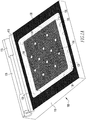
FIG. 1A is a perspective view of an embodiment of a clot preparation device. -
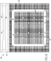
FIG. 1B is a perspective view of a top portion of the clot preparation device ofFIG. 1A . -
FIG. 2 is a perspective view of a combination clot forming tool. -
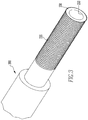
FIG. 3 is a perspective view of a distal end of the combination clot forming tool illustrated inFIG. 2 . -
FIG. 4 is a perspective view of a side of an embodiment of a clot delivery device. -
FIG. 5 is a perspective view of a top of the clot preparation device ofFIG. 1B with the clot forming tool ofFIG. 2 and the clot delivery device ofFIG. 4 . -
FIG. 6 is a perspective view of a top of the clot preparation device ofFIG. 1B with an alternate combination clot forming tool and the clot delivery device ofFIG. 4 . -
FIG. 7 is a perspective view of a cup in use with the combination clot forming tool illustrated inFIG. 2 . -
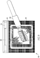
FIG. 8 is a perspective view of a top of the clot preparation device ofFIG. 1B with the clot forming tool ofFIG. 2 depositing clot material on a gauze pad. -
FIG. 9 is a perspective view of a top of the clot preparation device ofFIG. 1B with the clot forming tool ofFIG. 2 preparing clot material on a gauze pad. - This application incorporates by reference in its entirety
U.S. Provisional Application No. 62/471,419 WO2018/169719A1 , Appl. No.PCT/US2018/020999 . - An embodiment of a
clot preparation device 100 is illustrated inFigs. 1A ,1B ,5 ,6 ,8 , and9 . Theclot preparation device 100 includes abase 110, awork surface 120 supported on thebase 110, andmultiple drainage openings 150. As most clearly shown in theFig. 1A illustration, thebase 110 supports thework surface 120, that is sloped from horizontal when thebase 110 is placed on a horizontal surface. This enables asloped work surface 120. The depicted slope is toward the operator, but in other embodiments, the slope may be in another effective direction. Thework surface 120 illustrated has anupper working area 122, and aperimeter 130 around the upper workingarea 122. In the embodiment illustrated, the upper workingarea 122 includes the peaks of knurls created in the work surface 120 (Fig. 1B ). - The
perimeter 130 depicted includes a channel that is at least in part lower than an adjacent part of the upper workingarea 122 so that fluid placed on the upper workingarea 122 will drain into the channel under the force of gravity when thebase 110 is placed on a horizontal surface. As used here, "lower" means at a lesser elevation when theclot preparation device 100 is sitting on itsbase 110 on a horizontal surface. The illustrated channel in theperimeter 130 extends around theentire perimeter 130, but in other embodiments, the channel may be in only a portion of theperimeter 130. Thework surface 120 depicted includes alower working area 124 below the upper workingarea 122 configured such that fluid placed on the upper workingarea 122 will drain into thelower working area 124 under the force of gravity when thebase 110 is placed on a horizontal surface. In the embodiment illustrated, thelower working area 124 includes the valleys of the knurls (Fig. 1B ). As shown, there are two or more sloped regions between the knurl peaks of the upper workingarea 122 and the knurl valleys of thelower working area 124. As illustrated inFigs. 8 and9 , the knurl peaks at the upper workingarea 122 are configured to support aclot 2000 being prepared on theclot preparation device 100. Particularly, in the illustrated embodiment, support of theclot 2000 is also provided by agauze pad 1100 that rests primarily on the knurl peaks of the upper workingarea 122. In other embodiments, another material may be substituted for gauze or an additional support component such as thegauze pad 1100 may be omitted. The valleys of thelower working area 124 shown extend in two directions, but in other embodiments may only extend in one direction or may extend in more than two directions. In some embodiments, a clot may be another type of graft material, such as but not limited to, autograft, allograft, a synthetic graft, or any substance or composition which is useful in the healing of tissue. For example and without limitation, clots or grafts of various embodiments of the invention may be blood components, such as fibrin derived from blood, collagen, ligaments, tendons, or any combinations or components of any of these. -
Multiple drainage openings 150 are shown in the channel inFigs. 1A and1B and through more central portions of thework surface 120. However, in other embodiments, one ormore drainage openings 150 may be located only in the channel around theperimeter 130 and not necessarily in more central portions of thework surface 120. In still other embodiments, one ormore drainage openings 150 may be located only in more central portions of thework surface 120 and not in the channel around theperimeter 130. - As shown in
Figs. 1A ,1B ,5 ,6 ,8 , and9 , theclot preparation device 100 may include adelivery device holder 105 comprising an indention in theclot preparation device 100. Additionally, theclot preparation device 100 may include a supplementaldelivery device holder 115 configured to receive anadditional delivery device 500. An example of adelivery device 500 is depicted inFigs. 4-6 . Thedelivery device 500 includes atubular body 510, adistal end 501, aproximal end 502, aproximal opening 515 through which aproximal plunger 512 may be inserted, and a portal 504 through which graft material and aplunger 506 may be inserted. Theproximal plunger 512 and theplunger 506 are configured to move within thedelivery device 500 proximally-distally to move graft material through and potentially out of thedistal end 501 of thedelivery device 500. Asleeve 520 is also illustrated rotatably coupled around thetubular body 510 adjacent to the portal 504. Thesleeve 520 includes an opening and may be rotated relative to thetubular body 510 to close or open the portal 504. Thedelivery device 500 also includes acap 511 at thedistal end 501 that is removable. Several other delivery devices that could be used in various embodiments are disclosed inWO2018/169719A1 , which has been incorporated by reference herein in its entirety. The various delivery device embodiments are referred to in that application as an, "instrument for containing a graft configured for delivery." - The
delivery device holder 105 or the supplementaldelivery device holder 115 may receive thedelivery device 500, the delivery devices incorporated by reference, and any other delivery devices that will couple into the holders provided. In the illustrated embodiment, theclot preparation device 100 also includes a deliverydevice holder connector 155 into which a part of a delivery device, such as thedelivery device 500, is releasably connectable. In one example (Figs. 5 and6 ), the deliverydevice holder connector 155 couples with thetubular body 510 of thedelivery device 500 to hold thedelivery device 500 relative to theclot preparation device 100. - An embodiment of a combination
clot forming tool 200 is illustrated inFigs. 2 ,3 ,5 ,8 , and9 . The combinationclot forming tool 200 shown includes ahandle 210 with a first diameter about a longitudinal axis of the combinationclot forming tool 200 and aroller 220 coupled to thehandle 210. Theroller 220 illustrated has a second diameter about the longitudinal axis of the combinationclot forming tool 200 that is greater than the first diameter of thehandle 210. As shown inFig. 9 , theroller 220 may have a smooth surface configured to press against and flatten ablood clot 2000 without substantially adhering to theblood clot 2000 when rolled over theblood clot 2000. The smooth surface of theroller 220, or other embodiments of a roller, may be made from the same material as all or part of the remainder of theclot forming tool 200. For example, the material may be plastic, glass, or metallic. In other embodiments, a roller of a clot forming tool may be a special material or coating engineered to reduce adhesion to a blood clot or other graft material. An alternate embodiment of a roller is a roller attachment 3200 (Fig. 6 ). Theroller attachment 3200 is removably connectable to an instrument for positioning agraft 3000. Embodiments of the instrument for positioning a graft may include at respective ends: elevators, spatulas, paddles with various curvatures or shapes, graspers, hooks, etc., to enable various angles of approach to a graft or for the handling of different types of graft. The "handling instruments" shown inWO2018/169719A1 , which is incorporated by reference herein in its entirety, provide illustrations of other possible end configurations for embodiments of the instrument for positioning a graft. Other embodiments of the handling instrument would not necessarily include a paddle or other handling component on each end of the handling instrument. - The
clot forming tool 200 shown also includes aclot collection end 230 coupled to theroller 220. Theclot collection end 230 has a third diameter about the longitudinal axis of the combinationclot forming tool 200 that is less than the second diameter of theroller 220. Theclot collection end 230 depicted has asurface 235 configured to enhance formation of a blood clot when passed through blood. Such use is shown inFig. 7 where theclot collection end 230 is being used to agitate blood in acup 600. Thesurface 235 is a knurled surface with intersecting peaks and valleys in two substantially perpendicular directions. Other embodiments may include etched surfaces, roughened surfaces, scored surfaces, coated surfaces, or other surface treatments, or portions with surfaces made from other materials upon which clots form, such as, but not limited to: glass, ceramic, and corrosion resistant metals such as stainless steel. As most easily seen inFig. 3 , theclot collection end 230 may include a tubular shape with acannulation 233. Other embodiments may have different wall thicknesses or be partially or completely solid. - An embodiment of the invention is an instrument set that includes the
clot preparation device 100, the combinationclot forming tool 200, and one or more of thedelivery devices 500 configured to be held in theclot preparation device 100. Instrument set embodiments may include any of the variations of the clot preparation device, combination clot forming tool, and the delivery devices disclosed. Instrument set embodiments may also include two or more delivery devices. In some embodiments, the instrument set may also include an instrument for positioning a graft, such as the instrument for positioning agraft 3000 described in association withFig. 6 . The alternate embodiment of the roller, theattachment roller 3200, is illustrated in use inFig. 6 . Theroller attachment 3200 illustrated is configured to be removably coupled to the instrument for positioning agraft 3000. Theroller attachment 3200 shown includes a smooth surface configured to press against and flatten a clot, such as theclot 2000, without substantially adhering to theclot 2000 when rolled over theclot 2000. The smooth surface of theroller attachment 3200 may be made from the same material as all or part of the remainder of the instrument for positioning agraft 3000. For example, the material may be metallic, plastic, or glass. In other embodiments, a roller of a clot forming tool may be a special material or coating engineered to reduce adhesion to a blood clot or other graft material. - The instrument set may also include the
cup 600, as illustrated inFig. 7 . Thecup 600 may be made from any type of material able to be sterilized effectively that will not unnecessarily adhere to the graft or clot material being prepared. For example and without limitation, thecup 600 may be made from glass or stainless steel. Embodiments of thecup 600 are not limited to a cylindrical container open at one end and may be any shape or size of effective container. - An embodiment of the invention is a method of delivering graft material to a surgical site. The surgical site may be any surgical repair site that may benefit from the delivery of a graft material. For example and without limitation, the surgical site may be a meniscal repair site within a patient's knee such as a tear that is to be sutured or otherwise closed or amended. Acts of the method embodiment may include forming a clot 2000 (
Figs. 8 and9 ) on a portion of a clot forming tool, such as thesurface 235 of theclot collection end 230 of the combinationclot forming tool 200, that has a first diameter. These acts in some embodiments include obtaining about a 60CC volume of blood from a patient and placing the blood into a small beaker or other vessel (cup 600 inFig. 7 , for example). The blood is illustrated being stirred with a distal end of the combinationclot forming tool 200 by the action arrow inFig. 7 . The distal end illustrated is the clot collection end 230 (Figs. 2 and3 ). Thesurface 235 depicted is a knurled surface, but in other embodiments may be etched surfaces, roughened surfaces, scored surfaces, coated surfaces, or any other surface capable of collecting clotting material, or portions with surfaces made from other materials upon which clots form, such as but not limited to glass, ceramic, and corrosion resistant metals such as stainless steel. More generally, a patient's or a donor's blood may be collected in thecup 600 and a tool or instrument may be used to stir or agitate the blood to promote clotting on a surface of the tool or instrument. - The method may include moving the
clot 2000 from theclot forming tool 200 to aclot preparation device 100 that includes abase 110 and awork surface 120 supported on thebase 110. The illustratedwork surface 120 includes anupper working area 122, and aperimeter 130 around the upper workingarea 122 in at least part of which is formed a channel that is lower than an adjacent part of the upper workingarea 122 so that fluid placed on the upper workingarea 122 will drain into the channel under the force of gravity when thebase 110 is placed on a horizontal surface. In the embodiment depicted, thework surface 120 includesmultiple drainage openings 150 through thework surface 120. Moving of theclot 2000 that was deposited on thesurface 235 from theclot forming tool 200 is specifically illustrated inFig. 8 . Theclot 2000 being moved may include a single layer or in multiple layers of fibrin. In this illustration, theclot 2000 is being rolled off of thesurface 235 and onto thegauze pad 1100 by rolling theclot forming tool 200 along the gauze pad 1100 (bottom of page to top of page as drawn). Other embodiments may not include anintermediary gauze pad 1100, and theclot 2000 may be placed directly on thework surface 120. In other embodiments, the moving of theclot 2000 may be accomplished using one or more other instruments that may be used to grasp theclot 2000 to remove theclot 2000 from thesurface 235 and then place theclot 2000 onto theclot preparation device 100. - Method embodiments may also include pressing the
clot 2000 against the upper workingarea 122 to remove liquid from theclot 2000 with a portion of theclot forming tool 200 that has a second diameter larger than the first diameter. In the illustration ofFig. 9 , theroller 220 is the portion of theclot forming tool 200 being used to press theclot 2000 against thegauze pad 1100 and the upper workingarea 122 to remove liquid from theclot 2000. As used herein, the terms pressing theclot 2000 against the upper workingarea 122 includes pressing theclot 2000 against thegauze pad 1100 when thegauze pad 1100 is supported on the upper workingarea 122. The illustratedroller 220 is a middle region of theclot forming tool 200. The pressing illustrated inFig. 9 is with a smooth surface configured to press against and flatten theclot 2000 without substantially adhering to theclot 2000. - Once the
clot 2000 has been flattened, theclot 2000 must be prepared for delivery to the surgical site, typically by creating smaller pieces of theclot 2000. For example and without limitation, theclot 2000 may be held with forceps while scissors are used to cut theclot 2000 into thin strips or small pieces. The thin strips or small pieces may be placed directly into a surgical site, or an additional instrument may be used to deliver the thin strips or small pieces of theclot 2000 to the surgical site. Oneexample delivery device 500 is shown inFigs. 4-6 . For thedelivery device 500, delivering a portion of theclot 2000 to the surgical site may include placing strips or pieces into thedelivery device 500 through the portal 504. Theplunger 506 may be inserted through the portal 504 and advanced distally within thedelivery device 500 to move strips or small pieces through thedelivery device 500 and out of thedistal end 501 of thedelivery device 500. Theproximal plunger 512 may be inserted through theproximal opening 515 and advanced distally within thedelivery device 500 to move strips or small pieces through thedelivery device 500 and out of thedistal end 501 of thedelivery device 500. Thecap 511 at thedistal end 501 is configured to be removed from thedelivery device 500 before thedelivery device 500 is in its final position for clot or graft delivery. As previously noted, several other delivery devices that could be used in various embodiments are disclosed inWO2018/169719A1 , which has been incorporated by reference herein in its entirety. - In addition to loading a first clot delivery device, such as the
delivery device 500, while the first clot delivery device is located in the firstdelivery device holder 105, after the first clot delivery device has been loaded, the first clot delivery device may be placed in a seconddelivery device holder 115 while a second clot delivery device is placed in the firstdelivery device holder 105 and loaded. In the illustrated example ofFigs. 5 and6 , the deliverydevice holder connector 155 of the firstdelivery device holder 105 couples withtubular body 510 of thedelivery device 500 while thedelivery device 500 is loaded. In addition to or as an alternative, delivering a portion of the pressed clot to the surgical site may include using an instrument for positioning a graft, such as the instrument for positioning a graft 3000 (Fig. 6 ), to place the pressed clot at the surgical site. - Various embodiments of an instrument or instrument set wholly or its components individually may be made from any biocompatible material. For example and without limitation, biocompatible materials may include in whole or in part: non-reinforced polymers, reinforced polymers, metals, ceramics, glass, adhesives, reinforced adhesives, and combinations of these materials. Reinforcing of polymers may be accomplished with carbon, metal, or glass or any other effective material. Examples of biocompatible polymer materials include polyamide base resins, polyethylene, Ultra High Molecular Weight (UHMW) polyethylene, low density polyethylene, polymethylmethacrylate (PMMA), polyetheretherketone (PEEK), polyetherketoneketone (PEKK), a polymeric hydroxyethylmethacrylate (PHEMA), and polyurethane, any of which may be reinforced. Example biocompatible metals include stainless steel and other steel alloys, cobalt chrome alloys, zirconium, oxidized zirconium, tantalum, titanium, titanium alloys, titanium-nickel alloys such as Nitinol and other superelastic or shape-memory metal alloys.
- Terms such as distal, proximal, below, horizontal, lower, and the like have been used relatively herein. However, such terms are not limited to specific coordinate orientations, distances, or sizes, but are used to describe relative positions referencing particular embodiments. Such terms are not generally limiting to the scope of the claims made herein. Any embodiment or feature of any section, portion, or any other component shown or particularly described in relation to various embodiments of similar sections, portions, or components herein may be interchangeably applied to any other similar embodiment or feature shown or described herein.
- While embodiments of the invention have been illustrated and described in detail in the disclosure, the disclosure is to be considered as illustrative and not restrictive in character. All changes and modifications that come within the spirit of the invention are to be considered within the scope of the disclosure.
Claims (11)
- A clot preparation device comprising:a base;a work surface supported on the base, the work surface comprising:an upper working area, anda perimeter around the upper working area in at least part of which is formed a channel that is lower than an adjacent part of the upper working area so that fluid placed on the upper working area will drain into the channel under the force of gravity when the base is placed on a horizontal surface; anda drainage opening through the work surface.
- The clot preparation device of claim 1 wherein the base supports the work surface to create a work surface that is sloped from horizontal when the base is placed on a horizontal surface.
- The clot preparation device of claim 1 wherein the work surface includes a lower working area below the upper working area configured such that fluid placed on the upper working area will drain into the lower working area under the force of gravity when the base is placed on a horizontal surface.
- The clot preparation device of claim 3 wherein there are two or more sloped regions between the upper working area and the lower working area.
- The clot preparation device of claim 3 wherein there are peaks at the upper working area configured to support a clot being prepared on the clot preparation device and valleys at the lower working area.
- The clot preparation device of claim 1 wherein the channel includes a drainage opening.
- The clot preparation device of claim 1 wherein the channel extends along substantially all of the perimeter.
- The clot preparation device of claim 7 wherein the channel includes a drainage opening.
- The clot preparation device of claim 1 wherein the clot preparation device includes a delivery device holder comprising an indention in the clot preparation device.
- The clot preparation device of claim 9 wherein the clot preparation device includes a supplemental delivery device holder configured to receive an additional delivery device.
- The clot preparation device of claim 1 wherein the clot preparation device includes a delivery device holder connector into which a part of a delivery device is releasably connectable.
Applications Claiming Priority (1)
| Application Number | Priority Date | Filing Date | Title |
|---|---|---|---|
| US201962894994P | 2019-09-03 | 2019-09-03 |
Publications (1)
| Publication Number | Publication Date |
|---|---|
| EP3789052A1 true EP3789052A1 (en) | 2021-03-10 |
Family
ID=72266100
Family Applications (1)
| Application Number | Title | Priority Date | Filing Date |
|---|---|---|---|
| EP20190961.1A Pending EP3789052A1 (en) | 2019-09-03 | 2020-08-13 | Fibrin clot preparation instruments and method |
Country Status (3)
| Country | Link |
|---|---|
| US (1) | US11779929B2 (en) |
| EP (1) | EP3789052A1 (en) |
| CN (1) | CN112438782A (en) |
Citations (7)
| Publication number | Priority date | Publication date | Assignee | Title |
|---|---|---|---|---|
| FR2519840A1 (en) * | 1982-01-21 | 1983-07-22 | Forez Ste Laitiere | Plastics pot for drainage and retailing of cream cheese - has drain holes only through base of channel around inwardly domed base |
| US20150080791A1 (en) * | 2009-02-26 | 2015-03-19 | Javin C. Pierce | System for harvesting and dispensing a fibrin clot |
| US20160256593A1 (en) * | 2009-01-27 | 2016-09-08 | Reddress Ltd. | Wound dressings, methods and apparatus for making same and storage and use thereof |
| WO2018169719A1 (en) | 2017-03-15 | 2018-09-20 | Smith & Nephew, Inc. | Graft preparation and delivery instruments and method |
| US20180311404A1 (en) * | 2015-10-27 | 2018-11-01 | Hélio Nogueira da SILVA JUNIOR | Device for preparing a biological wound dressing made of autologous fibrin |
| KR20190020990A (en) * | 2017-08-22 | 2019-03-05 | 김태윤 | Prf-film processing apparatus for self blood procedure |
| US20190133881A1 (en) * | 2017-11-03 | 2019-05-09 | Enso Discoveries, Llc | Apparatus and method for processing platelet rich fibrin |
Family Cites Families (7)
| Publication number | Priority date | Publication date | Assignee | Title |
|---|---|---|---|---|
| US4790819A (en) | 1987-08-24 | 1988-12-13 | American Cyanamid Company | Fibrin clot delivery device and method |
| RU2273487C2 (en) | 2004-06-17 | 2006-04-10 | Государственное образовательное учреждение высшего профессионального образования Амурская государственная медицинская академия Министерства здравоохранения Российской Федерации | Method for producing fibrin paste |
| EP2146794B1 (en) * | 2007-04-12 | 2016-10-19 | Biomet Biologics, LLC | Buoy suspension fractionation system |
| WO2009074154A2 (en) * | 2007-12-10 | 2009-06-18 | Dako Denmark A/S | A tissue processing apparatus |
| US20100228175A1 (en) | 2009-02-26 | 2010-09-09 | Pierce Javin C | System for harvesting and dispensing blood clot |
| JP2016532876A (en) * | 2013-09-06 | 2016-10-20 | セラノス, インコーポレイテッド | Equipment, systems, methods and kits for receiving wipes |
| IL244922A0 (en) | 2016-04-05 | 2016-07-31 | Omrix Biopharmaceuticals Ltd | Device and process for sample preparation |
-
2020
- 2020-08-13 EP EP20190961.1A patent/EP3789052A1/en active Pending
- 2020-08-17 US US16/995,121 patent/US11779929B2/en active Active
- 2020-08-26 CN CN202010870191.2A patent/CN112438782A/en active Pending
Patent Citations (7)
| Publication number | Priority date | Publication date | Assignee | Title |
|---|---|---|---|---|
| FR2519840A1 (en) * | 1982-01-21 | 1983-07-22 | Forez Ste Laitiere | Plastics pot for drainage and retailing of cream cheese - has drain holes only through base of channel around inwardly domed base |
| US20160256593A1 (en) * | 2009-01-27 | 2016-09-08 | Reddress Ltd. | Wound dressings, methods and apparatus for making same and storage and use thereof |
| US20150080791A1 (en) * | 2009-02-26 | 2015-03-19 | Javin C. Pierce | System for harvesting and dispensing a fibrin clot |
| US20180311404A1 (en) * | 2015-10-27 | 2018-11-01 | Hélio Nogueira da SILVA JUNIOR | Device for preparing a biological wound dressing made of autologous fibrin |
| WO2018169719A1 (en) | 2017-03-15 | 2018-09-20 | Smith & Nephew, Inc. | Graft preparation and delivery instruments and method |
| KR20190020990A (en) * | 2017-08-22 | 2019-03-05 | 김태윤 | Prf-film processing apparatus for self blood procedure |
| US20190133881A1 (en) * | 2017-11-03 | 2019-05-09 | Enso Discoveries, Llc | Apparatus and method for processing platelet rich fibrin |
Also Published As
| Publication number | Publication date |
|---|---|
| US11779929B2 (en) | 2023-10-10 |
| US20210060546A1 (en) | 2021-03-04 |
| CN112438782A (en) | 2021-03-05 |
Similar Documents
| Publication | Publication Date | Title |
|---|---|---|
| JP5583333B2 (en) | Kit used to make a part of a joint prosthesis for use in arthroplasty | |
| Hacking et al. | Fibrous tissue ingrowth and attachment to porous tantalum | |
| US10882229B2 (en) | Methods and devices for applying bone cement to orthopedic prostheses to enhance bond strength | |
| AU2004216201B2 (en) | Bone and cartilage implant delivery device | |
| JP4776912B2 (en) | Apparatus for delivering an arthroscopic tissue scaffold | |
| US20070021838A1 (en) | Site specific minimally invasive joint implants | |
| US20110009872A1 (en) | Implant delivery device and method | |
| US20110159457A1 (en) | Blood absorbing device | |
| KR20180014814A (en) | Implant placement and removal systems | |
| US9937057B2 (en) | Delivery device | |
| EP0674888A1 (en) | Mixing device | |
| JP2007050272A (en) | Composite bone marrow graft material and its method and kit | |
| EP3294144A1 (en) | Bone fragment and tissue harvesting system | |
| AU2008340311A1 (en) | Cannula | |
| US20060198877A1 (en) | Medical instrument for autologous chondrocyte transplantation | |
| DE69932866D1 (en) | METHOD AND DEVICE TO ENABLE THE IMPLANTATION OF BIOLOGICAL MATERIALS | |
| JP2022500100A (en) | Bone material mixing and dispensing equipment and methods | |
| EP3789052A1 (en) | Fibrin clot preparation instruments and method | |
| US20090149774A1 (en) | bone marrow aspiration needle | |
| US11510696B2 (en) | Graft preparation and delivery instruments and method | |
| US10709579B2 (en) | Bone graft dispensing device | |
| DE102007024083B4 (en) | Zementapplikator | |
| US20220287718A1 (en) | Open-pore surgical vessel clip for closing blood vessels | |
| RU33302U1 (en) | Bone graft collection device | |
| AU2022305260A1 (en) | Multi-layered biomimetic osteochondral implants |
Legal Events
| Date | Code | Title | Description |
|---|---|---|---|
| PUAI | Public reference made under article 153(3) epc to a published international application that has entered the european phase |
Free format text: ORIGINAL CODE: 0009012 |
|
| STAA | Information on the status of an ep patent application or granted ep patent |
Free format text: STATUS: THE APPLICATION HAS BEEN PUBLISHED |
|
| AK | Designated contracting states |
Kind code of ref document: A1 Designated state(s): AL AT BE BG CH CY CZ DE DK EE ES FI FR GB GR HR HU IE IS IT LI LT LU LV MC MK MT NL NO PL PT RO RS SE SI SK SM TR |
|
| AX | Request for extension of the european patent |
Extension state: BA ME |
|
| STAA | Information on the status of an ep patent application or granted ep patent |
Free format text: STATUS: REQUEST FOR EXAMINATION WAS MADE |
|
| 17P | Request for examination filed |
Effective date: 20210910 |
|
| RBV | Designated contracting states (corrected) |
Designated state(s): AL AT BE BG CH CY CZ DE DK EE ES FI FR GB GR HR HU IE IS IT LI LT LU LV MC MK MT NL NO PL PT RO RS SE SI SK SM TR |
|
| STAA | Information on the status of an ep patent application or granted ep patent |
Free format text: STATUS: EXAMINATION IS IN PROGRESS |
|
| 17Q | First examination report despatched |
Effective date: 20231206 |