EP0674888A1 - Mixing device - Google Patents
Mixing device Download PDFInfo
- Publication number
- EP0674888A1 EP0674888A1 EP95102744A EP95102744A EP0674888A1 EP 0674888 A1 EP0674888 A1 EP 0674888A1 EP 95102744 A EP95102744 A EP 95102744A EP 95102744 A EP95102744 A EP 95102744A EP 0674888 A1 EP0674888 A1 EP 0674888A1
- Authority
- EP
- European Patent Office
- Prior art keywords
- mixing
- container
- piston
- mixing device
- substances
- Prior art date
- Legal status (The legal status is an assumption and is not a legal conclusion. Google has not performed a legal analysis and makes no representation as to the accuracy of the status listed.)
- Granted
Links
Images

Classifications
-
- B—PERFORMING OPERATIONS; TRANSPORTING
- B65—CONVEYING; PACKING; STORING; HANDLING THIN OR FILAMENTARY MATERIAL
- B65D—CONTAINERS FOR STORAGE OR TRANSPORT OF ARTICLES OR MATERIALS, e.g. BAGS, BARRELS, BOTTLES, BOXES, CANS, CARTONS, CRATES, DRUMS, JARS, TANKS, HOPPERS, FORWARDING CONTAINERS; ACCESSORIES, CLOSURES, OR FITTINGS THEREFOR; PACKAGING ELEMENTS; PACKAGES
- B65D81/00—Containers, packaging elements, or packages, for contents presenting particular transport or storage problems, or adapted to be used for non-packaging purposes after removal of contents
- B65D81/32—Containers, packaging elements, or packages, for contents presenting particular transport or storage problems, or adapted to be used for non-packaging purposes after removal of contents for packaging two or more different materials which must be maintained separate prior to use in admixture
- B65D81/3255—Containers provided with a piston or a movable bottom, and permitting admixture within the container
-
- A—HUMAN NECESSITIES
- A61—MEDICAL OR VETERINARY SCIENCE; HYGIENE
- A61B—DIAGNOSIS; SURGERY; IDENTIFICATION
- A61B17/00—Surgical instruments, devices or methods, e.g. tourniquets
- A61B17/56—Surgical instruments or methods for treatment of bones or joints; Devices specially adapted therefor
- A61B17/58—Surgical instruments or methods for treatment of bones or joints; Devices specially adapted therefor for osteosynthesis, e.g. bone plates, screws, setting implements or the like
- A61B17/88—Osteosynthesis instruments; Methods or means for implanting or extracting internal or external fixation devices
- A61B17/8802—Equipment for handling bone cement or other fluid fillers
- A61B17/8805—Equipment for handling bone cement or other fluid fillers for introducing fluid filler into bone or extracting it
- A61B17/8825—Equipment for handling bone cement or other fluid fillers for introducing fluid filler into bone or extracting it characterised by syringe details
-
- A—HUMAN NECESSITIES
- A61—MEDICAL OR VETERINARY SCIENCE; HYGIENE
- A61B—DIAGNOSIS; SURGERY; IDENTIFICATION
- A61B17/00—Surgical instruments, devices or methods, e.g. tourniquets
- A61B17/56—Surgical instruments or methods for treatment of bones or joints; Devices specially adapted therefor
- A61B17/58—Surgical instruments or methods for treatment of bones or joints; Devices specially adapted therefor for osteosynthesis, e.g. bone plates, screws, setting implements or the like
- A61B17/88—Osteosynthesis instruments; Methods or means for implanting or extracting internal or external fixation devices
- A61B17/8802—Equipment for handling bone cement or other fluid fillers
- A61B17/8805—Equipment for handling bone cement or other fluid fillers for introducing fluid filler into bone or extracting it
- A61B17/8827—Equipment for handling bone cement or other fluid fillers for introducing fluid filler into bone or extracting it with filtering, degassing, venting or pressure relief means
-
- B—PERFORMING OPERATIONS; TRANSPORTING
- B01—PHYSICAL OR CHEMICAL PROCESSES OR APPARATUS IN GENERAL
- B01F—MIXING, e.g. DISSOLVING, EMULSIFYING OR DISPERSING
- B01F31/00—Mixers with shaking, oscillating, or vibrating mechanisms
- B01F31/44—Mixers with shaking, oscillating, or vibrating mechanisms with stirrers performing an oscillatory, vibratory or shaking movement
- B01F31/441—Mixers with shaking, oscillating, or vibrating mechanisms with stirrers performing an oscillatory, vibratory or shaking movement performing a rectilinear reciprocating movement
-
- B—PERFORMING OPERATIONS; TRANSPORTING
- B01—PHYSICAL OR CHEMICAL PROCESSES OR APPARATUS IN GENERAL
- B01F—MIXING, e.g. DISSOLVING, EMULSIFYING OR DISPERSING
- B01F33/00—Other mixers; Mixing plants; Combinations of mixers
- B01F33/50—Movable or transportable mixing devices or plants
- B01F33/501—Movable mixing devices, i.e. readily shifted or displaced from one place to another, e.g. portable during use
- B01F33/5011—Movable mixing devices, i.e. readily shifted or displaced from one place to another, e.g. portable during use portable during use, e.g. hand-held
- B01F33/50112—Movable mixing devices, i.e. readily shifted or displaced from one place to another, e.g. portable during use portable during use, e.g. hand-held of the syringe or cartridge type
-
- B—PERFORMING OPERATIONS; TRANSPORTING
- B01—PHYSICAL OR CHEMICAL PROCESSES OR APPARATUS IN GENERAL
- B01F—MIXING, e.g. DISSOLVING, EMULSIFYING OR DISPERSING
- B01F35/00—Accessories for mixers; Auxiliary operations or auxiliary devices; Parts or details of general application
- B01F35/71—Feed mechanisms
- B01F35/713—Feed mechanisms comprising breaking packages or parts thereof, e.g. piercing or opening sealing elements between compartments or cartridges
- B01F35/7131—Breaking or perforating packages, containers or vials
-
- B—PERFORMING OPERATIONS; TRANSPORTING
- B01—PHYSICAL OR CHEMICAL PROCESSES OR APPARATUS IN GENERAL
- B01F—MIXING, e.g. DISSOLVING, EMULSIFYING OR DISPERSING
- B01F35/00—Accessories for mixers; Auxiliary operations or auxiliary devices; Parts or details of general application
- B01F35/71—Feed mechanisms
- B01F35/713—Feed mechanisms comprising breaking packages or parts thereof, e.g. piercing or opening sealing elements between compartments or cartridges
- B01F35/7137—Piercing, perforating or melting membranes or closures which seal the compartments
-
- B—PERFORMING OPERATIONS; TRANSPORTING
- B01—PHYSICAL OR CHEMICAL PROCESSES OR APPARATUS IN GENERAL
- B01F—MIXING, e.g. DISSOLVING, EMULSIFYING OR DISPERSING
- B01F35/00—Accessories for mixers; Auxiliary operations or auxiliary devices; Parts or details of general application
- B01F35/71—Feed mechanisms
- B01F35/717—Feed mechanisms characterised by the means for feeding the components to the mixer
- B01F35/718—Feed mechanisms characterised by the means for feeding the components to the mixer using vacuum, under pressure in a closed receptacle or circuit system
-
- A—HUMAN NECESSITIES
- A61—MEDICAL OR VETERINARY SCIENCE; HYGIENE
- A61F—FILTERS IMPLANTABLE INTO BLOOD VESSELS; PROSTHESES; DEVICES PROVIDING PATENCY TO, OR PREVENTING COLLAPSING OF, TUBULAR STRUCTURES OF THE BODY, e.g. STENTS; ORTHOPAEDIC, NURSING OR CONTRACEPTIVE DEVICES; FOMENTATION; TREATMENT OR PROTECTION OF EYES OR EARS; BANDAGES, DRESSINGS OR ABSORBENT PADS; FIRST-AID KITS
- A61F2/00—Filters implantable into blood vessels; Prostheses, i.e. artificial substitutes or replacements for parts of the body; Appliances for connecting them with the body; Devices providing patency to, or preventing collapsing of, tubular structures of the body, e.g. stents
- A61F2/02—Prostheses implantable into the body
- A61F2/30—Joints
- A61F2002/30001—Additional features of subject-matter classified in A61F2/28, A61F2/30 and subgroups thereof
- A61F2002/30316—The prosthesis having different structural features at different locations within the same prosthesis; Connections between prosthetic parts; Special structural features of bone or joint prostheses not otherwise provided for
- A61F2002/30535—Special structural features of bone or joint prostheses not otherwise provided for
- A61F2002/30561—Special structural features of bone or joint prostheses not otherwise provided for breakable or frangible
-
- A—HUMAN NECESSITIES
- A61—MEDICAL OR VETERINARY SCIENCE; HYGIENE
- A61F—FILTERS IMPLANTABLE INTO BLOOD VESSELS; PROSTHESES; DEVICES PROVIDING PATENCY TO, OR PREVENTING COLLAPSING OF, TUBULAR STRUCTURES OF THE BODY, e.g. STENTS; ORTHOPAEDIC, NURSING OR CONTRACEPTIVE DEVICES; FOMENTATION; TREATMENT OR PROTECTION OF EYES OR EARS; BANDAGES, DRESSINGS OR ABSORBENT PADS; FIRST-AID KITS
- A61F2/00—Filters implantable into blood vessels; Prostheses, i.e. artificial substitutes or replacements for parts of the body; Appliances for connecting them with the body; Devices providing patency to, or preventing collapsing of, tubular structures of the body, e.g. stents
- A61F2/02—Prostheses implantable into the body
- A61F2/30—Joints
- A61F2/46—Special tools or methods for implanting or extracting artificial joints, accessories, bone grafts or substitutes, or particular adaptations therefor
- A61F2002/4685—Special tools or methods for implanting or extracting artificial joints, accessories, bone grafts or substitutes, or particular adaptations therefor by means of vacuum
-
- A—HUMAN NECESSITIES
- A61—MEDICAL OR VETERINARY SCIENCE; HYGIENE
- A61F—FILTERS IMPLANTABLE INTO BLOOD VESSELS; PROSTHESES; DEVICES PROVIDING PATENCY TO, OR PREVENTING COLLAPSING OF, TUBULAR STRUCTURES OF THE BODY, e.g. STENTS; ORTHOPAEDIC, NURSING OR CONTRACEPTIVE DEVICES; FOMENTATION; TREATMENT OR PROTECTION OF EYES OR EARS; BANDAGES, DRESSINGS OR ABSORBENT PADS; FIRST-AID KITS
- A61F2250/00—Special features of prostheses classified in groups A61F2/00 - A61F2/26 or A61F2/82 or A61F9/00 or A61F11/00 or subgroups thereof
- A61F2250/0058—Additional features; Implant or prostheses properties not otherwise provided for
- A61F2250/0071—Additional features; Implant or prostheses properties not otherwise provided for breakable or frangible
-
- B—PERFORMING OPERATIONS; TRANSPORTING
- B01—PHYSICAL OR CHEMICAL PROCESSES OR APPARATUS IN GENERAL
- B01F—MIXING, e.g. DISSOLVING, EMULSIFYING OR DISPERSING
- B01F2101/00—Mixing characterised by the nature of the mixed materials or by the application field
- B01F2101/20—Mixing of ingredients for bone cement
-
- B—PERFORMING OPERATIONS; TRANSPORTING
- B01—PHYSICAL OR CHEMICAL PROCESSES OR APPARATUS IN GENERAL
- B01F—MIXING, e.g. DISSOLVING, EMULSIFYING OR DISPERSING
- B01F23/00—Mixing according to the phases to be mixed, e.g. dispersing or emulsifying
- B01F23/50—Mixing liquids with solids
- B01F23/565—Mixing liquids with solids by introducing liquids in solid material, e.g. to obtain slurries
-
- B—PERFORMING OPERATIONS; TRANSPORTING
- B01—PHYSICAL OR CHEMICAL PROCESSES OR APPARATUS IN GENERAL
- B01F—MIXING, e.g. DISSOLVING, EMULSIFYING OR DISPERSING
- B01F33/00—Other mixers; Mixing plants; Combinations of mixers
- B01F33/70—Mixers specially adapted for working at sub- or super-atmospheric pressure, e.g. combined with de-foaming
-
- B—PERFORMING OPERATIONS; TRANSPORTING
- B01—PHYSICAL OR CHEMICAL PROCESSES OR APPARATUS IN GENERAL
- B01F—MIXING, e.g. DISSOLVING, EMULSIFYING OR DISPERSING
- B01F35/00—Accessories for mixers; Auxiliary operations or auxiliary devices; Parts or details of general application
- B01F35/30—Driving arrangements; Transmissions; Couplings; Brakes
- B01F35/32—Driving arrangements
- B01F35/32005—Type of drive
- B01F35/3202—Hand driven
Definitions
- the present invention relates to a mixing device for mixing at least two substances, preferably liquid monomer and powdery polymer, for producing bone cement, the two substances being mixed in a mixing space in a mixing container, preferably under partial vacuum, and wherein both substances are separated from one another are arranged separately in a container.
- Implantation technology in medical medicine has made considerable progress in recent years.
- the application methods for bone cement in the implantation of prostheses and the use of bone cement as a placeholder in restorative surgery have made astonishing progress.
- the next step in the application method was the complete elimination of manual contact with the cement by mixing in a special beaker from which the mixed cement could be introduced directly into the cartridge.
- the lifespan of implanted prostheses was largely dependent on the skill of the surgeons.
- the life expectancy of the implants was based on the perfection with which the cement was mixed and applied. Life expectancy hardly depended on the quality of the prosthesis (apart from the known shaft fractures), since bone cement was far below the life expectancy of the prosthesis.
- the doctors and researchers recognized a significant development deficit and researched the basic causes of the failure of the bone cements. There were two main causes for the relatively short life expectancy of the bone cements.
- L. Lidgren developed a method for mixing bone cements while reducing the proportion of pores. Functionally, this was the mixing of the bone cements under vacuum in the application cartridge. The monomer is thus filled into the cartridge, the polymer powder is poured on and the cartridge is sealed with a mixing device. After applying a vacuum, the cement is now mixed with the monomer under vacuum. This is followed by a swelling time, also under vacuum, and only then is the bone cement applied from the cartridge using a pistol and a snorkel.
- This system of cement mixing and application is commercially available under the name "Optivac" from MIT AB and corresponding studies have proven the effectiveness and safety of this system.
- US Pat. No. 4,463,875 describes a mixing device in which two substances to be mixed are packed separately in advance in the mixing device. The substances are brought into contact with one another and then mixed. In order to do this, the packaging is loaded with reciprocating movements from the outside, so that it deforms and thereby mixes the two substances.
- the disadvantage here is that no bone cement of the desired quality has been achieved with these mixing movements.
- a complicated container design is required in order to be able to carry out these mixing movements.
- US Pat. No. 4,973,168 describes a mixing device in which one of the substances to be mixed is packaged in advance in the mixing device, while the other substance is packaged in a separate container independently of the mixing device.
- the container is emptied into the mixing device, after which the substance of the container is packaged with the one in advance in the mixing device Material is mixed by an internal mixer.
- the disadvantage here is that a separate container is necessary for the one substance and that there is a risk that the separate container is not completely emptied, or that part of the substance of the separate container is spilled and the bone cement obtained therefore does not meet the quality requirements Fulfills.
- the European patent application EP 0 194 508 also mentioned describes a mixing device for mixing other agents, no vacuum being generated.
- the present invention intends to create a mixing device which makes it possible to improve the previous mixing technique and to largely rule out preparation errors before the mixing.
- the cement components can already be sterile in the mixing container without additional manipulations, which leads, among other things, to a reduction in technical manipulations and a minimization of the environmental risk and the amount of waste.
- the risk of contamination from the bone cement is reduced and there is no additional waste. Be too Errors in the sequence of the mixing process excluded.
- the mixing container 1 shown in FIG. 1 has the shape of a cartridge in which bone cement 2 is finished and applied with it.
- This mixing container 1 preferably consists of a cylindrical container 3 which is sealed on one side with a lid 4 and on the opposite side with a displaceable piston 5.
- a mixing element 6 consists of a handle 7 and an attached stirring element 8, which is located in a mixing space 9.
- the handle 7 is elongated and slidable and preferably also rotatably mounted in the lid 4, so that it can be moved and rotated from the outside in order to be able to move the stirring element 8 back and forth in the mixing space 9 and preferably to rotate in order to be in the mixing space 9 Mix fabrics.
- the cover 4 has a connecting pipe 10 which can be closed with a removable closure 11.
- a vacuum-generating device 12 can be connected to the connecting pipe 10 by means of a hose 13 (see FIG. 2) in order to generate partial vacuum, preferably 60-95% vacuum, in the mixing space 9.
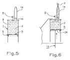
- an emptying tube 14 can be attached to the connecting tube 10 (see FIGS. 5 and 6), as a result of which finished bone cement 2 is emptied from the mixing space 9 in order to apply it.
- the bone cement 2 with the piston 5 is pressed out of the mixing chamber 9, the piston 5 being pressed with a pressure device 15, e.g. a pressure gun, is moved (see Fig. 6).
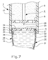
- the piston 5 consists of a wall 19 and a sleeve-shaped part 20 which extends outward from the wall 19 in relation to the mixing chamber 9.
- the outer side 21 of the wall 19 and the part 20 lies sealingly and displaceably against the inner side 22 of the cylindrical container 3.
- a connection opening 24 which is closed by a membrane 25.
- This membrane 25 is opened with an opener 26, e.g. pierced with a mandrel 26 on the stirring element 8, whereby the wall 19 is opened and thereby a connection 27 between the interior of the container 18 and the mixing space 9 is established.
- the sleeve-shaped part 20 can have a cylindrical shape and on the outside 21 a groove 28 running around the same.
- a sleeve-shaped end part 29 of the container 18 engages in this groove 28 and this end part 29 surrounds the sleeve-shaped part 20 of the piston 5 and is sealing arranged this.
- the walls 30 of the container 18 consist for example of several layers, an inner layer 31 made of plastic, e.g. Polyethylene, and an outer layer 32 of metal material, e.g. Aluminum.
- the inner layer 31 bears against the sleeve-shaped part 20 of the piston 5, which part 20 is preferably made of the same or similar plastic material, e.g. Polyethylene, such as layer 31.
- the plastic material of the piston 5 and the inner layer 31 of the container 18 can be fused together by heat treatment, the heat e.g. by s.g. Ultra-frequency welding can be achieved.
- the mixing space 9 of the mixing container 1, preferably at the place For example, in an operating room where the mixing is to be carried out, connected to the vacuum generating device 12, partial vacuum being generated in the mixing room 9.
- the mixing element 6 is then used as an opener 26, the mandrel 26 being pressed through the membrane 25.
- the connection 27 produced in this way immediately causes the partial vacuum from the monomer 16 in the container 18 and causes it to be sucked out of the container 18 into the mixing space 9, ie to the polymer 17 therein (see FIG. 2).
- the walls 30 of the container 18 are designed (for example, so flexibly and / or elastically) that they are sucked together so that the container 18 is completely or almost completely emptied (see FIG. 3).
- the mixing is carried out by pushing the mixing element 6 now used for the mixing back and forth in the mixing chamber 9 and possibly rotating it until the monomer 16 and the polymer 17 are sufficient have mixed (see Fig. 3). With this mixture, partial vacuum is preferably generated in the mixing space 9 by the vacuum-generating device 12.
- a holding member 33 which holds the piston 5 to an end part of the cylindrical container 3, is removed (see FIG. 4), as a result of which the partial vacuum in the mixing chamber 9 sucks the piston 5 into the container 3.
- the bone cement 2 and lumps of bone cement which are stuck at various points in the mixing chamber 9 are collected in the mixing chamber 9 at the cover 4.
- the hose 13 to the vacuum-generating device 12 is removed from the connecting pipe 10 and the emptying pipe 14 is connected to the connecting pipe 10 (see FIG. 5). Then the mixing tank 1 is placed in the pressure device 15 and the piston 5 is pressed with it in the direction against the cover 4, as a result of which the bone cement 2 is pressed out of the mixing chamber 9 through the emptying tube 14.
- the piston 5 is displaced with a pressure element 34 of the pressure device 15, the container walls 30 lying between the piston 5 and the pressure element 34.
- the container walls 30 can preferably take place in the sleeve-shaped part 20 of the piston 5 and / or be sucked into it and thus do not prevent the pressure element 34 from being pushed into this sleeve-shaped part 20 (see FIG. 6).
- the walls 30 of the container 18 can consist of such a metal material that the substance 16 is protected therein in the event of radiation effects that occur during radiation sterilization.
- Both the container 18 and the interior of the mixing container 1 can be sterilized.
- the mixing container 1 can be a mixing cup, for example, from which the bone cement 2 finished therein is filled into a cartridge in order to be applied therewith.
- Partial vacuum can also be within the limits of 60-95% and may be generated in the mixing container 1 beforehand.
- the substance 17 can be packaged in an extra container packed in the mixing space 9, the piston 5 and / or the container 18 can have other shapes. however, the container 18 can be arranged in a different position than on the piston 5.
- the opener for opening the wall 19 is described as a mandrel 26 on the mixing element 6 and shown, but the same can consist of another organ which is arranged differently.
Abstract
Description
Die vorliegende Erfindung bezieht sich auf eine Mischvorrichtung zum Mischen von zumindest zwei Stoffen, vorzugsweise flüssiger Monomer und pulverförmiger Polymer, zum Herstellen von Knochenzement, wobei die zwei Stoffe in einem Mischraum in einem Mischbehälter, vorzugsweise unter partiellem Vakuum, gemischt werden und wobei beide Stoffe voneinander getrennt in je einem Behälter angeordnet sind.The present invention relates to a mixing device for mixing at least two substances, preferably liquid monomer and powdery polymer, for producing bone cement, the two substances being mixed in a mixing space in a mixing container, preferably under partial vacuum, and wherein both substances are separated from one another are arranged separately in a container.
Die Implantationstechnik in der medizinischen Heilkunde hat in den letzten Jahren erhebliche Fortschritte erzielt. Speziell die Applikationsmethoden für Knochenzemente bei der Implantation von Prothesen bzw. die Verwendung von Knochenzement als Platzhalter in der restaurativen Chirurgie erreichten erstaunliche Fortschritte.Implantation technology in medical medicine has made considerable progress in recent years. In particular, the application methods for bone cement in the implantation of prostheses and the use of bone cement as a placeholder in restorative surgery have made astonishing progress.
In der Ursprungszeit der Knochenzemente wurden diese unter normalen atmosphärischen Bedingungen in einem Becher angerührt, mit der Hand geknetet, zu "Würsten" geformt und in den zu füllenden Defekt eingeführt und per Hand verdichtet. Diese Methode hat sich lange Zeit als die einzig mögliche Applikationsmethode für Knochenzemente gehalten.In the original period, the bone cements were mixed under normal atmospheric conditions in a beaker, kneaded by hand, molded into "sausages" and inserted into the defect to be filled and compacted by hand. This method has long been the only possible application method for bone cements.
Daran anschliessend wurde eine Verbesserung in Form einer Applikation über eine Kartusche entwickelt. In dieser Ära wurde der Zement ebenfalls unter normalen atmosphärischen Bedingungen angerührt, dann aber in eine Kartusche umgefüllt und durch diese mittels eines mechanischen Kraftübertragungsapparates (Pistole) aus der Kartuschenmündung herausgepresst.Subsequently, an improvement in the form of an application via a cartridge was developed. In this era, the cement was also mixed under normal atmospheric conditions, but then poured into a cartridge and pressed out of the cartridge mouth by means of a mechanical power transmission device (pistol).
Der nächste Fortschritt in der Applikationsmethode war die vollständige Elimination eines Handkontaktes mit dem Zement, indem das Anrühren in einem speziellen Becher erfolgte, von dem aus der angerührte Zement direkt in die Kartusche eingeführt werden konnte.The next step in the application method was the complete elimination of manual contact with the cement by mixing in a special beaker from which the mixed cement could be introduced directly into the cartridge.
In diesen Zeiten war die Lebensdauer von implantierten Prothesen überwiegend vom Geschick der Operateure abhängig. Die Lebenserwartung der Implantate richtete sich nach der Perfektion, mit der der Zement angerührt und appliziert wurde. Die Lebenserwartung hing kaum von der Qualität der Prothese ab (bis auf die bekannten Schaftbrüche), da Knochenzement in seiner Lebenserwartung weit unter der der Prothesen lag. Hier erkannten die Mediziner und Forscher ein wesentliches Entwicklungsdefizit und erforschten die grundlegenden Ursachen für das Versagen der Knochenzemente. Im wesentlichen ergaben sich zwei Hauptursachen für die relativ kurze Lebenserwartung der Knochenzemente. Zum einen war es eine nicht vollständige Mischung der Monomere mit den Polymeren, was zu geringen und unterschiedlichen Primärfestigkeiten innerhalb des Zementmantels um die Prothesen führte und was durch nicht gebundene und auspolmerisierte Monomer- und Polymeranteile zu toxikologischen Problemen und entzündlichen Gewebereaktionen führte. Zum zweiten ergaben sich bei den Untersuchungen mechanische Inhomogenitäten in dem Zement, hervorgerufen durch eingeschlossene Luftblasen, welche die Dauerschwingfestigkeit der Knochenzemente erheblich nachteilig beeinflussen. Aber auch grobe Defekte durch eingeschlossene Luftblasen bewirkten einen vorzeitigen Bruch des Zementmantels.During these times, the lifespan of implanted prostheses was largely dependent on the skill of the surgeons. The life expectancy of the implants was based on the perfection with which the cement was mixed and applied. Life expectancy hardly depended on the quality of the prosthesis (apart from the known shaft fractures), since bone cement was far below the life expectancy of the prosthesis. Here the doctors and researchers recognized a significant development deficit and researched the basic causes of the failure of the bone cements. There were two main causes for the relatively short life expectancy of the bone cements. For one thing it was an incomplete mixture of the monomers with the polymers, what led to low and different primary strengths within the cement mantle around the prostheses and what led to toxicological problems and inflammatory tissue reactions due to unbound and polymerized monomer and polymer components. Secondly, the investigations revealed mechanical inhomogeneities in the cement, caused by enclosed air bubbles, which have a significant adverse effect on the fatigue strength of the bone cements. However, gross defects caused by trapped air bubbles caused the cement jacket to break prematurely.
Nach der weitestgehenden Verminderung oder Elimination von Infektionen durch die Integration von antibakteriellen Wirkstoffen in den Zementen, die ihrerseits die Lebenserwartung zementierter Prothesen verlängerten, ergab sich klar die Notwendigkeit, auch die mechanischen Eigenschaften der Knochenzemente zu verbessern, ebenfalls mit dem Ziel längerer Prothesenstandzeiten.After the reduction or elimination of infections as far as possible through the integration of antibacterial agents in the cements, which in turn prolonged the life expectancy of cemented prostheses, there was a clear need to improve the mechanical properties of the bone cements, also with the aim of prolonged prosthesis service life.
Diesen Erkenntnissen Rechnung tragend, entwickelte L. Lidgren eine Methode zur Anmischung von Knochenzementen unter gleichzeitiger Reduzierung der Porenanteile. Funktionell war dies die Anmischung der Knochenzemente unter Vakuum in der Applikationskartusche. So wird das Monomer in die Kartusche eingefüllt, das Polymerpulver aufgeschüttet und die Kartusche mit einer Mischeinrichtung verschlossen. Nach Anlegen eines Vakuums wird der Zement nun mit dem Monomer unter Vakuum gemischt. Es folgt eine Quellzeit, ebenfalls unter Vakuum, und erst dann wird der Knochenzement mittels einer Pistole aus der Kartusche über einen Schnorchel appliziert. Dieses System der Zementanmischung und Applikation ist unter dem Namen "Optivac" der Firma MIT AB in Handel und entsprechende Studien haben die Effektivität und die Sicherheit dieses Systems belegt.Taking these findings into account, L. Lidgren developed a method for mixing bone cements while reducing the proportion of pores. Functionally, this was the mixing of the bone cements under vacuum in the application cartridge. The monomer is thus filled into the cartridge, the polymer powder is poured on and the cartridge is sealed with a mixing device. After applying a vacuum, the cement is now mixed with the monomer under vacuum. This is followed by a swelling time, also under vacuum, and only then is the bone cement applied from the cartridge using a pistol and a snorkel. This system of cement mixing and application is commercially available under the name "Optivac" from MIT AB and corresponding studies have proven the effectiveness and safety of this system.
Experimentell konnte bewiesen werden, das durch einen derartigen Mischvorgang die Porosität (Anzahl und Grösse der Lufteinschlüsse) der Zementmatrix deutlich verringert und infolgedessen die mechanische Festigkeit eines so angemischten Zementes wesentlich verbessert werden kann.It could be demonstrated experimentally that such a mixing process significantly reduces the porosity (number and size of air pockets) of the cement matrix and, as a result, the mechanical strength of a cement mixed in this way can be significantly improved.
Eine Literaturübersicht bezüglich der oben erwähnten Mischung von Knochenzementen unter Vakuum folgt am Schluss dieser Beschreibung.A literature review regarding the above-mentioned mixture of bone cements under vacuum follows at the end of this description.
Aus der Patentliteratur seien die US-Patentschriften 4 463 875 und 4 973 168 sowie die europäische Patentanmeldung EP 0 194 508 erwähnt.From the patent literature, US Patents 4,463,875 and 4,973,168 as well as European Patent Application EP 0 194 508 are mentioned.
Die US-Patentschrift 4 463 875 beschreibt eine Mischvorrichtung, wobei zwei zu mischende Stoffe im voraus getrennt voneinander in der Mischvorrichtung verpackt sind. Die Stoffe werden miteinander in Kontakt gebracht und dann gemischt. Um dies durchzuführen, wird die Verpackung von aussen mit hin- und hergehenden Bewegungen belastet, so dass sie sich verformt und dadurch die beiden Stoffe mischt. Nachteilig hierbei ist, dass mit diesen Mischbewegungen kein Knochenzement mit erstrebter Qualität erreicht wurde. Ausserdem ist eine komplizierte Behälterausführung erforderlich, um diese Mischbewegungen ausführen zu können.US Pat. No. 4,463,875 describes a mixing device in which two substances to be mixed are packed separately in advance in the mixing device. The substances are brought into contact with one another and then mixed. In order to do this, the packaging is loaded with reciprocating movements from the outside, so that it deforms and thereby mixes the two substances. The disadvantage here is that no bone cement of the desired quality has been achieved with these mixing movements. In addition, a complicated container design is required in order to be able to carry out these mixing movements.
Die US-Patentschrift 4 973 168 beschreibt eine Mischvorrichtung, in der der eine Stoff von den zu mischenden Stoffen im voraus in der Mischvorrichtung verpackt ist, während der andere Stoff unabhängig von der Mischvorrichtung in einem separaten Behälter verpackt ist. Zum Mischen der beiden Stoffe wird der Behälter in die Mischvorrichtung entleert, wonach der Stoff des Behälters mit dem im voraus in der Mischvorrichtung verpackten Stoff durch ein inneres Mischorgan gemischt wird. Nachteilig hierbei ist, dass ein separater Behälter für den einen Stoff notwendig ist und dass das Risiko vorliegt, dass nämlich der separate Behälter nicht vollständig entleert wird, oder dass ein Teil des Stoffes des separaten Behälters verschüttet wird und der erhaltene Knochenzement deshalb nicht die gestellten Qualitätsforderungen erfüllt.US Pat. No. 4,973,168 describes a mixing device in which one of the substances to be mixed is packaged in advance in the mixing device, while the other substance is packaged in a separate container independently of the mixing device. To mix the two substances, the container is emptied into the mixing device, after which the substance of the container is packaged with the one in advance in the mixing device Material is mixed by an internal mixer. The disadvantage here is that a separate container is necessary for the one substance and that there is a risk that the separate container is not completely emptied, or that part of the substance of the separate container is spilled and the bone cement obtained therefore does not meet the quality requirements Fulfills.
Die weiterhin erwähnte europäische Patentanmeldung EP 0 194 508 beschreibt eine Mischvorrichtung für die Mischung anderer Mittel, wobei kein Vakuum erzeugt wird.The European patent application EP 0 194 508 also mentioned describes a mixing device for mixing other agents, no vacuum being generated.
Die vorliegende Erfindung beabsichtigt, eine Mischvorrichtung zu schaffen, die es ermöglicht, die bisherige Mischtechnik zu verbessern und auch Vorbereitungsfehler vor der Mischung weitgehend auszuschliessen.The present invention intends to create a mixing device which makes it possible to improve the previous mixing technique and to largely rule out preparation errors before the mixing.
Dies wird gemäss der Erfindung dadurch erreicht, dass die Mischvorrichtung die im Anspruch 1 definierten Merkmale aufweist.This is achieved according to the invention in that the mixing device has the features defined in
Durch diese Merkmale wird insbesondere erreicht, dass keine Umfüllung der Stoffe notwendig ist, und ein Verschütten zumindest des einen Stoffes ausgeschlossen wird, und dass die Stoffe ausserdem genügend effektiv gemischt werden können, um einen Knochenzement mit der erstrebten Qualität zu erhalten.These features in particular ensure that no transfer of the substances is necessary, and spillage of at least one substance is ruled out, and that the substances can moreover be mixed sufficiently effectively to obtain a bone cement of the desired quality.
Hierdurch können auch die Zementkomponenten steril ohne zusätzliche Handgriffe bereits zur Anmischung im Mischbehälter vorliegen, was u.a. zu einer Reduzierung der technischen Handgriffe und Minimierung der Umweltgefahr und der Abfallmengen führt. Ausserdem wird das Kontaminationsrisiko durch den Knochenzement reduziert und es entstehen keine zusätzlichen Abfallmengen. Auch werden Fehler bei der Reihenfolge des Anmischvorgangs ausgeschlossen.As a result, the cement components can already be sterile in the mixing container without additional manipulations, which leads, among other things, to a reduction in technical manipulations and a minimization of the environmental risk and the amount of waste. In addition, the risk of contamination from the bone cement is reduced and there is no additional waste. Be too Errors in the sequence of the mixing process excluded.
Die Mischvorrichtung gemäss der Erfindung wird in der folgenden Beschreibung mit Hinweis auf die nachfolgenden Zeichnungen näher beschrieben, wobei zeigt:
- Fig. 1
- schematisch einen Mischbehälter gemäss der Erfindung mit einer Seitenansicht, wobei zwei Stoffe getrennt von einander in zwei Behältern angeordnet sind;
- Fig. 2
- schematisch den Mischbehälter gemäss Fig. 1 beim öffnen einer Verbindung zwischen den zwei Behältern, wobei in dem einen Behälter Vakuum erzeugt wird;
- Fig. 3
- schematisch den Mischbehälter gemäss Fig. 1 beim Mischen der Stoffes in einem Mischraum in dem Vakuum herrscht;
- Fig. 4
- schematisch den Mischbehälter gemäss Fig. 1 beim Aufsammeln unter Vakuum des aus den Stoffen bestehenden Knochenzementes in dem Mischraum;
- Fig. 5
- schematisch den Mischbehälter gemäss Fig. 1 mit daran angeschlossenen Entleerrohr;
- Fig. 6
- schematisch den Mischbehälter gemäss Fig. 1 beim Entleeren des Knochenzements mit einer Druckvorrichtung; und
- Fig. 7
- einen vergrösserten Schnitt von einen Teil des Mischbehälters gemäss Fig. 1.
- Fig. 1
- schematically a mixing container according to the invention with a side view, wherein two substances are arranged separately from each other in two containers;
- Fig. 2
- schematically the mixing container of Figure 1 when opening a connection between the two containers, wherein vacuum is generated in the one container.
- Fig. 3
- schematically the mixing container according to Figure 1 when mixing the substance in a mixing room in the vacuum prevails;
- Fig. 4
- schematically the mixing container according to Figure 1 when collecting under vacuum of the bone cement consisting of the substances in the mixing room.
- Fig. 5
- schematically the mixing container according to Figure 1 with an attached drain pipe.
- Fig. 6
- schematically the mixing container of Figure 1 when emptying the bone cement with a pressure device. and
- Fig. 7
- 2 shows an enlarged section of part of the mixing container according to FIG. 1.
Der in Fig. 1 gezeigte Mischbehälter 1 hat die Form einer Kartusche, in der Knochenzement 2 fertiggestellt und mit dieser appliziert wird. Dieser Mischbehälter 1 besteht vorzugsweise aus einem zylindrischen Behälter 3, der an der einen Seite mit einem Deckel 4 und an der entgegengesetzten Seite mit einem verschiebbaren Kolben 5 dicht verschlossen ist. Ein Mischorgan 6 besteht aus einem Griff 7 und einem daran befestigten Rührorgan 8, das sich in einem Mischraum 9 befindet. Der Griff 7 ist langgestreckt und verschiebbar und vorzugsweise auch drehbar im Deckel 4 gelagert, so dass er von aussen verschoben und gedreht werden kann, um das Rührorgan 8 im Mischraum 9 hin und her bewegen zu können und vorzugsweise zu drehen, um im Mischraum 9 befindliche Stoffe zu mischen.The mixing
Der Deckel 4 hat ein Anschlussrohr 10, das mit einem abnehmbaren Verschluss 11 verschliessbar ist. An der Anschlussrohr 10 kann eine vakuumerzeugende Vorrichtung 12 durch einen Schlauch 13 angeschlossen werden (siehe Fig. 2), um in dem Mischraum 9 partielles Vakuum, vorzugsweise 60 - 95 % Vakuum, zu erzeugen. Ausserdem kann an dem Anschlussrohr 10 ein Entleerrohr 14 befestigt werden (siehe Fig. 5 und 6), wodurch fertiggestellter Knochenzement 2 aus dem Mischraum 9 entleert wird, um diesen zu applizieren. Hierbei wird der Knochenzement 2 mit dem Kolben 5 aus dem Mischraum 9 gepresst, wobei der Kolben 5 mit einer Druckvorrichtung 15, z.B. einer Druckpistole, verschoben wird (siehe Fig. 6).The
In dem Mischraum 9 ist der eine Stoff 17, vorzugsweise Pulverförmiger Polymer, angeordnet und in einem Behälter 18 ist getrennt davon ein anderer Stoff 16, vorzugsweise flüssiger Monomer, angeordnet. Diese Stoffe 16, 17 werden miteinander in Kontakt gebracht und gemischt um Knochenzement 2 davon herzustellen.One
Der Kolben 5 besteht aus einer Wand 19 und einem hülsenförmigen Teil 20 der von der Wand 19 in Richtung auswärts im Verhältnis zum Mischraum 9 verläuft. Die Aussenseite 21 der Wand 19 und des Teils 20 liegt dichtend und verschiebbar gegen die Innenseite 22 des zylindrischen Behälters 3 an. Im Zentrum der Wand 19 ist eine Verbindungsöffnung 24 angeordnet die durch einen Membran 25 abgeschlossen wird. Dieser Membran 25 wird mit einem Öffner 26 geöffnet, z.B. mit einem Dorn 26 am Rührorgan 8 durchstochen, wodurch die Wand 19 geöffnet wird und dadurch eine Verbindung 27 zwischen dem Inneren des Behälters 18 und dem Mischraum 9 zustande kommt.The
Der hülsenförmige Teil 20 kann zylindrische Form aufweisen und an der Aussenseite 21 eine rund um denselben verlaufende Nute 28. In diese Nute 28 greift ein hülsenförmiger Endteil 29 des Behälters 18 ein und dieser Endteil 29 umgibt den hülsenförmigen Teil 20 des Kolbens 5 und ist dichtend an diesen angeordnet.The sleeve-shaped
Die Wände 30 des Behälters 18 bestehen bespielsweise aus mehreren Schichten, wobei eine innere Schicht 31 aus Kunststoff, z.B. Polyäthylen, besteht und eine äussere Schicht 32 aus Metallmaterial, z.B. Aluminium, besteht.The
Die innere Schicht 31 liegt gegen den hülsenförmigen Teil 20 des Kolbens 5 an, welcher Teil 20 vorzugsweise aus demselben oder ähnlichen Kunststoffmaterial, z.B. Polyäthylen, wie die Schicht 31 besteht. Das Kunststoffmaterial des Kolbens 5 und der inneren Schicht 31 des Behälters 18 können mit einander durch Wärmebehandlung verschmolzen sein, wobei die Wärme z.B. durch s.g. Ultrafrequenzschweissen erreicht werden kann.The
Um die Mischoperation durchzuführen, wird der Mischraum 9 des Mischbehälters 1, vorzugsweise an dem Platz, z.B. in einem Operationsraum, wo die Mischung durchgeführt werden woll, an die vakuumerzeugende Vorrichtung 12 angeschlossen, wobei im Mischraum 9 partielles Vakuum erzeugt wird. Danach wird das Mischorgan 6 als Öffner 26 benutzt, wobei der Dorn 26 durch den Membran 25 gedrückt wird. Durch die hierbei hergestellte Verbindung 27 wirkt sofort das partielle Vakuum aus das Monomer 16 im Behälter 18 und bewirkt, dass dieses aus dem Behälter 18 in den Mischraum 9 gesaugt wird, d.h. zu dem Polymer 17 darin, strömt (siehe Fig. 2). Die Wände 30 des Behälters 18 sind so ausgeführt (z.B. so flexibel und/oder elastisch), dass dieselben hierbei zusammengesaugt werden sodass sich der Behälter 18 vollständig oder nahezu vollständig entleert (siehe Fig. 3).In order to carry out the mixing operation, the mixing
Nachdem Monomer 16 sich im Mischraum 9 in Kontakt mit dem Polymer 17 befindet, wird die Mischung durchgeführt, indem das nun zur Mischung verwendete Mischorgan 6 im Mischraum 9 hin und her geschoben und eventuell gedreht wird, bis sich das Monomer 16 und das Polymer 17 genügend gemischt haben (siehe Fig. 3). Bei dieser Mischung wird vorzugsweise partielles Vakuum im dem Mischraum 9 durch die vakuumerzeugende Vorrichtung 12 erzeugt.After
Danach wird ein Festhalteorgan 33, das den Kolben 5 an einem Endteil des zylindrischen Behälters 3 festhält, entfernt (siehe Fig. 4), wodurch das partielle Vakuum im Mischraum 9 den Kolben 5 in den Behälter 3 hinein saugt. Hierdurch wird der Knochenzement 2 und an verschiedenen Stellen im Mischraum 9 festsitzende Knochenzementklumpen im Mischraum 9 bei dem Deckel 4 aufgesammelt.Thereafter, a holding
Zum Entleeren des Mischraums 9 wird der Schlauch 13 zur vakuumerzeugenden Vorrichtung 12 vom Anschlussrohr 10 abgenommen und das Entleerrohr 14 an das Anschlussrohr 10 angeschlossen (siehe Fig. 5). Danach wird der Mischbehälter 1 in die Druckvorrichtung 15 gelegt und der Kolben 5 mit dieser in Richtung gegen den Deckel 4 gedrückt, wodurch der Knochenzement 2 durch das Entleerrohr 14 aus dem Mischraum 9 gedrückt wird. Der Kolben 5 wird mit einem Druckorgan 34 der Druckvorrichtung 15 verschoben, wobei die Behälterwände 30 zwischen dem Kolben 5 und dem Druckorgan 34 liegen. Die Behälterwände 30 können vorzugsweise in den hülsförmigen Teil 20 des Kolbens 5 platz nehmen und/oder in diesen hineingesaugt werden und hindern damit nicht dass das Druckorgan 34 in diesen hülsförmigen Teil 20 hineingeschoben wird (siehe Fig. 6).To empty the
Die Wände 30 des Behälters 18 können aus solchen Metallmaterial bestehen dass der Stoff 16 darin bei Strahlenwirkung, die bei der Bestrahlungssterilisierung auftritt, geschützt wird.The
Sowohl der Behälter 18 als auch das Innere des Mischbehälters 1 können sterilisiert sein.Both the
Die oben beschriebenen und in den Figuren gezeigten Ausführungen können im Rahmen der Patentansprüche variieren. Demnach kann beispielsweise der Mischbehälter 1 ein Mischbecher sein, von dem der darin fertiggestellte Knochenzement 2 in eine Kartusche gefüllt wird, um damit appliziert zu werden. Partielles Vakuum kann innerhalb aber auch ausserhalb der Grenzen 60 - 95 % liegen und eventuell schon im voraus im Mischbehälter 1 erzeugt sein.The embodiments described above and shown in the figures can vary within the scope of the claims. Accordingly, the mixing
Der Stoff 17 kann in einem in den Mischraum 9 verpackten Extrabehälter verpackt sein, der Kolben 5 und/oder der Behälter 18 kann/können andere Form/Formen aufweisen; der Behälter 18 kann jedoch in einer anderen Position als am Kolben 5 angeordnet sein. Der Öffner zum Öffnen der Wand 19 ist als Dorn 26 am Mischorgan 6 beschrieben und gezeigt, derselbe kann jedoch aus einem anderen Organ das andersartig angeordnet ist, bestehen.The
- 1. A charactarization of Polymethylmethacrylate bone cement. Haas, S S, Braner G M, Dickson G. J Bone Joint Surg, 57-A, 380-391, 1975. 1. A characterization of polymethyl methacrylate bone cement. Haas, SS, Braner GM, Dickson G. J Bone Joint Surg, 57-A, 380-391, 1975.
- 2. Strength of polymethylmethacrylate increased by vacuum mixing. Lidgren L, Drar H, Möller J. Acta Orthop Scand 55: 536-541, 1984. 2. Strength of polymethyl methacrylate increased by vacuum mixing. Lidgren L, Drar H, Möller J. Acta Orthop Scand 55: 536-541, 1984.
- 3 Bone cement improved by vacuum mixing and chilling. Lidgren L, Bodelind B, Möller J. Acta Orthop Scand 57: 27-32, 1987. 3 Bone cement improved by vacuum mixing and chilling. Lidgren L, Bodelind B, Möller J. Acta Orthop Scand 57: 27-32, 1987.
- 4. High vacuum as a method of reducing porosity of polymethlmethacrylate. Alkire M JH, Dabezies E J, Hastings P R. Orthopedics 10-11: 1533-1539, 1987. 4. High vacuum as a method of reducing porosity of polymethyl methacrylate. Alkire M JH, Dabezies EJ, Hastings P R. Orthopedics 10-11: 1533-1539, 1987.
- 5. Vacuum mixing of acrylic bone cement Wixson R L, Lautenschlager E P, Novak M A,. J Arthroplasty 2: 141-149, 1987. 5. Vacuum mixing of acrylic bone cement Wixson RL, Lautenschlager EP, Novak MA ,. J Arthroplasty 2: 141-149, 1987.
- 6. Effects of preparation techniques on the porosity of acrylic cements. Schreurs B W, Spierings T J, Huiskes R, Slooff J J H. Acta Orthop Scand 59(4): 403-409, 1988. 6. Effects of preparation techniques on the porosity of acrylic cements . Schreurs BW, Spierings TJ, Huiskes R, Slooff JJ H. Acta Orthop Scand 59 (4): 403-409, 1988.
- 7. Efficiency of bone cement mixing systems - A gas chromatographic study. Darre E, Vedel P, Steen Jensen J. Adv Orthop Surg 12: 106-108, 1988. 7. Efficiency of bone cement mixing systems - A gas chromatographic study. Darre E, Vedel P, Steen Jensen J. Adv Orthop Surg 12: 106-108, 1988.
- 8. Porosity in manually mixed bone cement. Linden U, Clin Orthop 231: 110-112, 1988. 8. Porosity in manually mixed bone cement. Linden U, Clin Orthop 231: 110-112, 1988.
- 9. Air inclusion in bone cement. Linden U, Gillquist J. Clin Orthop 247: 148-151, 1989. 9. Air inclusion in bone cement. Linden U, Gillquist J. Clin Orthop 247: 148-151, 1989.
- 10. Fatigue properties of bone cement. Linden U, Acta Orthop Scand 60: 431-433, 1989. 10. Fatigue properties of bone cement. Linden U, Acta Orthop Scand 60: 431-433, 1989.
- 11. A fractographic analysis of in vivo poly(methylmethacrylate) bone cement failure mechanism. Topoleski LDT, Ducheyne P, Cuckler JM. J Biomedical Materials Res. 24: 135-54, 1990. 11. A fractographic analysis of in vivo poly (methyl methacrylate) bone cement failure mechanism. Topoleski LDT, Ducheyne P, Cuckler JM. J Biomedical Materials Res. 24: 135-54, 1990.
- 12. Comparison of the diametral shrinkage of centrifuged and uncentrifuged. Davies J P, O'Connor D O, Burke D W, Harris W H. The 16th Annual Meeting of the Society for Biomaterials, 23, 1990. 12. Comparison of the diametral shrinkage of centrifuged and uncentrifuged. Davies JP, O'Connor DO, Burke DW, Harris W H. The 16th Annual Meeting of the Society for Biomaterials, 23, 1990.
- 13. Effect of pore size and morphology on fatigue crack initiation in acrylic bone cements. Gilbert J L, Menis D W, Smith S M, Lautenschlager E P, Wixson R W. The 16th Annual Meeting of the Society for Biomaterials, 103, 1990. 13. Effect of pore size and morphology on fatigue crack initiation in acrylic bone cements. Gilbert JL, Menis DW, Smith SM, Lautenschlager EP, Wixson R W. The 16th Annual Meeting of the Society for Biomaterials, 103, 1990.
- 14. Effect of vacuum mixing on interfacial bone cement fracture toughness. Menis D L, Wixson R L, Gilbert J L, Lautenschlager E P. The 16th Annual Meeting of the Society for Biomaterials, 67, 1990. 14. Effect of vacuum mixing on interfacial bone cement fracture toughness. Menis DL, Wixson RL, Gilbert JL, Lautenschlager E P. The 16th Annual Meeting of the Society for Biomaterials, 67, 1990.
- 15. Effect of vacuum mixing on the mechanical properties of antibiotic-impregnated polymethylmethacrylate bone cement. Askew M J: Kufel M F, Fleissner P R Jr., GradisarI A Jr., Salstrom S-A, Ton J S. J Biomed Maler Res 24: 573-580, 1990. 15. Effect of vacuum mixing on the mechanical properties of antibiotic-impregnated polymethyl methacrylate bone cement. Askew MJ: Kufel MF, Fleissner PR Jr., GradisarI A Jr., Salstrom SA, Ton J S. J Biomed Maler Res 24: 573-580, 1990.
- 16. Optimization and comparison of three vacuum mixing systems for porosity reduction of Simplex P cement. Davies J P, Harris W H. Clin Orthop 254: 261-269, 1990 16. Optimization and comparison of three vacuum mixing systems for porosity reduction of Simplex P cement. Davies JP, Harris W.H. Clin Orthop 254: 261-269, 1990
- 17. Porosity of various preparations of acrylic bone cements. Jasty M, Davies J, O'Connor D, Burke D, Harrigan T, Harris W. Clin Orthop 259: 122-129, 1990. 17. Porosity of various preparations of acrylic bone cements. Jasty M, Davies J, O'Connor D, Burke D, Harrigan T, Harris W. Clin Orthop 259: 122-129, 1990.
- 18. The effects of the mixing techniques of Gentamicin-loaded bone cement on the release of antibiotics. Wahling, H, Dingeldein E. Orthop Rel Sci. 1: 121-124, 1990. 18. The effects of the mixing techniques of Gentamicin-loaded bone cement on the release of antibiotics. Wahling, H, Dingeldein E. Orthop Rel Sci. 1: 121-124, 1990.
- 19. A fractographic investigation of PMMA bone cement focusing on the relationship between porosity reduction and increased fatigue life. James SP, Jasty M, Davies J, Piehler . J Biomed Mater Res 26: 651-62, 1992. 19. A fractographic investigation of PMMA bone cement focusing on the relationship between porosity reduction and increased fatigue life. James SP, Jasty M, Davies J, Piehler. J Biomed Mater Res 26: 651-62, 1992.
- 20. Borderline indications for use of cement in total joint replacements. Jasty M, Mulroy R, Harris W H. Chir Organi Mov 77(4): 397-404, 1992. 20. Borderline indications for use of cement in total joint replacements. Jasty M, Mulroy R, Harris W H. Chir Organi Mov 77 (4): 397-404, 1992.
- 21. Do we need to vacuum mix or centrifuge cement? Wixson R L. Clin Orthp 285: 84-90, 1992. 21. Do we need to vacuum mix or centrifuge cement? Wixson R. L. Clin Orthp 285: 84-90, 1992.
- 22. Influence of vacuum mixing on mechanical properties of homemade bone cement. Chen XX. Chung-Hua-Wai-Ko-Tsa-Chih, Oct, Vol: 30(10), 593-5, 635-6, 1992. 22. Influence of vacuum mixing on mechanical properties of homemade bone cement . Chen XX. Chung-Hua-Wai-Ko-Tsa-Chih, Oct, Vol: 30 (10), 593-5, 635-6, 1992.
- 23. Observation on PMMA bone cement with scanning electron-microscope:the efficacity of vacuum-mixing.Chen H-X, Lu H-S, Lin J-H. Arthritis Clinic & Research Center, People's Hospital, Beijing Medical University, Beijing, P.R. China. SIROT 93 Seoul VI World Congress, Korea, August 27-30, 1993. 23. Observation on PMMA bone cement with scanning electron microscope: the efficacity of vacuum mixing. Chen HX, Lu HS, Lin JH. Arthritis Clinic & Research Center, People's Hospital, Beijing Medical University, Beijing, PR China. SIROT 93 Seoul VI World Congress, Korea, August 27-30, 1993.
- 24. Porosity of bone cement reduced by mixing and collecting under vacuum. Wang J-S, Franzén H, Jonsson E, Lidgren L. Acta Orthop Scand 64(2): 143-146, 1993. 24. Porosity of bone cement reduced by mixing and collecting under vacuum. Wang JS, Franzén H, Jonsson E, Lidgren L. Acta Orthop Scand 64 (2): 143-146, 1993.
- 25. The effects of vacuum mixing on the microscopic homogenicity of palacos R bone cement. Wang J-S, Goodman S B, Franzén H, Aspenberg P, Lidgren L. Eur J Exp Musculoskeletal Res 2: 000-000, 1993. 25. The effects of vacuum mixing on the microscopic homogenicity of palacos R bone cement. Wang JS, Goodman SB, Franzén H, Aspenberg P, Lidgren L. Eur J Exp Musculoskeletal Res 2: 000-000, 1993.
Claims (21)
Applications Claiming Priority (2)
| Application Number | Priority Date | Filing Date | Title |
|---|---|---|---|
| DE4409610 | 1994-03-21 | ||
| DE4409610A DE4409610C3 (en) | 1994-03-21 | 1994-03-21 | Mixing device |
Publications (2)
| Publication Number | Publication Date |
|---|---|
| EP0674888A1 true EP0674888A1 (en) | 1995-10-04 |
| EP0674888B1 EP0674888B1 (en) | 2000-05-03 |
Family
ID=6513363
Family Applications (1)
| Application Number | Title | Priority Date | Filing Date |
|---|---|---|---|
| EP95102744A Expired - Lifetime EP0674888B1 (en) | 1994-03-21 | 1995-02-27 | Mixing device |
Country Status (5)
| Country | Link |
|---|---|
| US (1) | US5549380A (en) |
| EP (1) | EP0674888B1 (en) |
| JP (1) | JP3599250B2 (en) |
| DE (1) | DE4409610C3 (en) |
| DK (1) | DK0674888T3 (en) |
Cited By (22)
| Publication number | Priority date | Publication date | Assignee | Title |
|---|---|---|---|---|
| US5881536A (en) * | 1996-03-20 | 1999-03-16 | Mueller-Wille; Per | Method for sterile packing of a substance |
| EP0972499A3 (en) * | 1998-07-13 | 2001-03-28 | Stryker Technologies Corporation | Disposable monomer dispenser and vial breaker |
| WO2001070146A2 (en) * | 2000-02-28 | 2001-09-27 | Coripharm Medizinprodukte Gmbh & Co. Kg | Preparation and application device for implant materials |
| WO2004071884A2 (en) | 2003-02-13 | 2004-08-26 | Ilc Dover, Inc. | Flexible disposable vessel |
| WO2008022481A1 (en) * | 2006-08-22 | 2008-02-28 | Medmix Systems Ag | Device and method for storing, mixing and dispensing components |
| US7431837B2 (en) | 2003-02-13 | 2008-10-07 | Ilc Dover Lp | Mixing vessel and method of use |
| EP2052748A2 (en) | 2007-10-22 | 2009-04-29 | Heraeus Medical GmbH | Polymethyl methacrylate bone cement in paste form |
| EP2347819A1 (en) | 2010-01-26 | 2011-07-27 | Heraeus Medical GmbH | Mixing device and method for manufacturing polymethylmethacrylate bone cement pastes |
| DE102010055759A1 (en) | 2010-01-27 | 2011-07-28 | Heraeus Medical GmbH, 61273 | Bone cement paste, useful e.g. for fixing joint endoprostheses, comprises e.g. hydrophobic methacrylic acid ester, a filler, a radical initiator soluble in methacrylic acid ester, and an accelerator soluble in methacrylic acid ester |
| DE102010005956A1 (en) | 2010-01-27 | 2011-07-28 | Heraeus Medical GmbH, 61273 | Three-component bone cement and its use |
| DE102010024653A1 (en) | 2010-06-22 | 2011-12-22 | Heraeus Medical Gmbh | Pasty bone cement |
| EP2550980A2 (en) | 2011-07-27 | 2013-01-30 | Heraeus Medical GmbH | Bone cement in paste form |
| DE102012001637A1 (en) | 2012-01-30 | 2013-08-01 | Heraeus Medical Gmbh | Pasty bone cement |
| CN103251977A (en) * | 2011-12-20 | 2013-08-21 | 赫罗伊斯医疗有限责任公司 | Paste-like bone cement |
| EP2664349A1 (en) | 2012-05-16 | 2013-11-20 | Heraeus Medical GmbH | Bone cement in paste form |
| EP2687239A2 (en) | 2012-07-20 | 2014-01-22 | Heraeus Medical GmbH | Bone cement in paste form |
| DE102012014702A1 (en) | 2012-07-25 | 2014-01-30 | Heraeus Medical Gmbh | Pasty bone cement |
| US9186635B2 (en) | 2009-03-17 | 2015-11-17 | Stryker Ireland Limited | Vacuum mixing device for bone cement and method for mixing bone cement in said device |
| US9642774B2 (en) | 2011-09-07 | 2017-05-09 | Stryker European Holdings I, Llc | Liquid container with predetermined breaking point |
| US9750842B2 (en) | 2011-10-03 | 2017-09-05 | Hyalex Orthopaedics, Inc. | Polymeric adhesive for anchoring compliant materials to another surface |
| CN108031368A (en) * | 2017-11-30 | 2018-05-15 | 佛山市博思通信息技术有限公司 | A kind of Water powdery mixer |
| CN108065999A (en) * | 2016-11-11 | 2018-05-25 | 贺利氏医疗有限公司 | For storing and mixing the device and method of bone cement |
Families Citing this family (68)
| Publication number | Priority date | Publication date | Assignee | Title |
|---|---|---|---|---|
| SE9301599L (en) | 1993-05-10 | 1994-06-27 | Cemvac System Ab | Device for loading bone cement components into a pressurized mixing vessel |
| US6149655A (en) * | 1996-12-13 | 2000-11-21 | Norian Corporation | Methods and devices for the preparation, storage and administration of calcium phosphate cements |
| JP4271733B2 (en) * | 1996-12-13 | 2009-06-03 | ノリアン コーポレイション | Cement preparation, storage and administration |
| US5961210A (en) * | 1997-01-24 | 1999-10-05 | Mccardel; Brian R. | Bone cement preparation device, and methods of constructing and utilizing same |
| IL128261A0 (en) | 1999-01-27 | 1999-11-30 | Disc O Tech Medical Tech Ltd | Expandable element |
| US20070282443A1 (en) * | 1997-03-07 | 2007-12-06 | Disc-O-Tech Medical Technologies Ltd. | Expandable element |
| US6042262A (en) * | 1997-07-29 | 2000-03-28 | Stryker Technologies Corportion | Apparatus for storing, mixing, and dispensing two-component bone cement |
| US5951160A (en) * | 1997-11-20 | 1999-09-14 | Biomet, Inc. | Method and apparatus for packaging, mixing and delivering bone cement |
| US6024480A (en) * | 1998-02-09 | 2000-02-15 | Immedica | Vial package for a bone cement mixer and dispenser |
| US6298984B1 (en) * | 1999-01-22 | 2001-10-09 | Einstone, Inc. | Packaging for deactivated cement and cement activator and procedure for mixing deactivated cement and cement activator therein |
| US6116773A (en) * | 1999-01-22 | 2000-09-12 | Murray; William M. | Bone cement mixer and method |
| US7621950B1 (en) | 1999-01-27 | 2009-11-24 | Kyphon Sarl | Expandable intervertebral spacer |
| SE521945C2 (en) | 1999-02-26 | 2003-12-23 | Biomet Merck Cementing Technol | Mixing device for making bone cement |
| US6193058B1 (en) | 1999-03-05 | 2001-02-27 | Canberra Corportion | System for dispensing premeasured quantities of concentrated materials |
| US6099160A (en) * | 1999-03-23 | 2000-08-08 | Flacktek, Inc. | Mixing system for mixing and dispensing reactive materials |
| DE60042893D1 (en) * | 2000-01-06 | 2009-10-15 | Yamanaka Industry Co Ltd | ANTIBACTERIAL AND BIODEGRADABLE BUFFER |
| DE20005333U1 (en) * | 2000-02-28 | 2001-07-12 | Coripharm Medizinprodukte Gmbh | Preparation and application device for implant materials |
| SE520688C2 (en) | 2000-04-11 | 2003-08-12 | Bone Support Ab | An injectable bone mineral replacement material |
| US6379033B1 (en) | 2000-05-30 | 2002-04-30 | William M. Murray | Device for flowing bone cement liquid into bone cement powder |
| SE517168C2 (en) | 2000-07-17 | 2002-04-23 | Bone Support Ab | A composition for an injectable bone mineral replacement material |
| MY133943A (en) | 2000-08-22 | 2007-11-30 | Synthes Gmbh | Bone replacement material |
| CA2449970A1 (en) * | 2001-06-14 | 2002-12-27 | Cemvac System Ab | Method and device for preparation of bone cement |
| SE523307C2 (en) * | 2001-11-07 | 2004-04-13 | Biomet Merck Cementing Technol | Device for mixing devices for mixing powdered and liquid substances with each other for the manufacture of medical products |
| SE522098C2 (en) | 2001-12-20 | 2004-01-13 | Bone Support Ab | Artificial bone mineral substitute material useful as an X-ray contrast medium comprises ceramic and water soluble non-ionic X-ray contrast agent |
| US6874187B2 (en) | 2002-05-09 | 2005-04-05 | Stryker Instruments | Opener for medical container and tool |
| SE0300620D0 (en) | 2003-03-05 | 2003-03-05 | Bone Support Ab | A new bone substitute composition |
| WO2004080357A1 (en) | 2003-03-14 | 2004-09-23 | Ferreyro Irigoyen Roque Humber | Hydraulic device for the injection of bone cement in percutaneous vertebroplasty |
| US8066713B2 (en) | 2003-03-31 | 2011-11-29 | Depuy Spine, Inc. | Remotely-activated vertebroplasty injection device |
| US20050128867A1 (en) * | 2003-05-12 | 2005-06-16 | Henniges Bruce D. | Bone cement mixing and delivery system |
| US20040267272A1 (en) | 2003-05-12 | 2004-12-30 | Henniges Bruce D | Bone cement mixing and delivery system |
| US8415407B2 (en) | 2004-03-21 | 2013-04-09 | Depuy Spine, Inc. | Methods, materials, and apparatus for treating bone and other tissue |
| CN100368025C (en) * | 2003-08-08 | 2008-02-13 | 斯恩蒂斯有限公司 | Method for impregnating porous bone substitute material |
| US8579908B2 (en) | 2003-09-26 | 2013-11-12 | DePuy Synthes Products, LLC. | Device for delivering viscous material |
| SE0302983D0 (en) | 2003-11-11 | 2003-11-11 | Bone Support Ab | Apparatus for providing spongy bone with bone replacement and / or bone strengthening material and associated method |
| ATE361725T1 (en) * | 2003-12-01 | 2007-06-15 | Broockeville Corp N V | TWO-COMPONENT MIXING AND DISPENSING DEVICE |
| BRPI0418886A (en) * | 2004-06-03 | 2007-12-11 | Synthes Gmbh | device for impregnating a porous bone replacement material |
| SE527528C2 (en) | 2004-06-22 | 2006-04-04 | Bone Support Ab | Apparatus for the preparation of curable pulp and use of the apparatus |
| CA2575699C (en) | 2004-07-30 | 2014-07-08 | Disc-O-Tech Medical Technologies Ltd. | Methods, materials and apparatus for treating bone and other tissue |
| ITTO20040743A1 (en) * | 2004-10-27 | 2005-01-27 | Gianmarco Roggero | DISPOSABLE HOMOGENIZING DEVICE, AND ITS USE FOR THE PREPARATION OF HOMOGENIZED SAMPLES |
| US20060274601A1 (en) * | 2005-06-07 | 2006-12-07 | Seaton James P Jr | Prepacked cartridge mixing system |
| ITVI20050187A1 (en) * | 2005-06-28 | 2006-12-29 | Tecres Spa | CARTRIDGE FOR STERILE MIXING OF A BIPHASIC COMPOUND, PERTICULARLY FOR BICOMPONENT ACRYLIC RESINS |
| US9381024B2 (en) | 2005-07-31 | 2016-07-05 | DePuy Synthes Products, Inc. | Marked tools |
| US9918767B2 (en) | 2005-08-01 | 2018-03-20 | DePuy Synthes Products, Inc. | Temperature control system |
| US8057090B1 (en) * | 2005-08-31 | 2011-11-15 | Subrata Saha | Automated bone cement mixer |
| WO2007048016A2 (en) * | 2005-10-20 | 2007-04-26 | Synthes (U.S.A.) | Perfusion device and method |
| US8360629B2 (en) | 2005-11-22 | 2013-01-29 | Depuy Spine, Inc. | Mixing apparatus having central and planetary mixing elements |
| SE530233C2 (en) * | 2006-08-11 | 2008-04-08 | Biomet Cementing Technologies | Liquid container for bone cement mixers |
| SE530232C2 (en) * | 2006-08-11 | 2008-04-08 | Biomet Cementing Technologies | Liquid container for bone cement mixers |
| WO2008032322A2 (en) | 2006-09-14 | 2008-03-20 | Depuy Spine, Inc. | Bone cement and methods of use thereof |
| CA2747850C (en) | 2006-10-19 | 2013-05-14 | Depuy Spine, Inc. | Fluid delivery system |
| US8132958B2 (en) * | 2006-12-13 | 2012-03-13 | Renfro Charles K | Multi-chambered fluid mixing apparatus and method |
| DE202006019576U1 (en) * | 2006-12-29 | 2008-05-08 | Berentzen-Gruppe Ag | Multi-part two-chamber container for the separate packaging of liquids |
| SE531600C2 (en) * | 2007-10-10 | 2009-06-02 | Ortoviva Ab | Mixing system and mixing procedure for medical purposes |
| DE102007061696B4 (en) | 2007-12-19 | 2010-03-18 | Heraeus Medical Gmbh | Mixing device, especially for bone cements |
| US8256949B2 (en) * | 2007-12-27 | 2012-09-04 | Cook Medical Technologies Llc | Apparatus and method for mixing and dispensing a bone cement mixture |
| US20090281549A1 (en) * | 2008-05-12 | 2009-11-12 | Cook Incorporated | Bone cement mixing and delivery device and method of use |
| US9180137B2 (en) | 2010-02-09 | 2015-11-10 | Bone Support Ab | Preparation of bone cement compositions |
| DE102010026497B4 (en) * | 2010-07-07 | 2014-04-03 | Heraeus Medical Gmbh | Vakuumzementiersystem |
| DE102010046055B4 (en) * | 2010-09-22 | 2012-10-25 | Heraeus Medical Gmbh | Mixing device for Prepack vacuum cementing system |
| DE102011000487B4 (en) * | 2011-02-03 | 2015-02-05 | CAS Chemotechnische Abpack-Service GmbH | Apparatus and method for introducing a Baumontageklebe- and / or construction sealant in a container |
| DE102011119371B3 (en) * | 2011-11-25 | 2013-04-04 | Heraeus Medical Gmbh | Device for mixing bone cement |
| PL2958603T3 (en) | 2013-02-20 | 2018-10-31 | Bone Support Ab | Improved setting of hardenable bone substitute |
| WO2017191641A1 (en) * | 2016-05-04 | 2017-11-09 | Zelikman, Zarema | A mixing apparatus and method thereof |
| CN107089441B (en) * | 2017-06-13 | 2020-06-02 | 苏州中科生物医用材料有限公司 | Cartilage repair instrument |
| WO2020083841A1 (en) * | 2018-10-22 | 2020-04-30 | Sulzer Mixpac Ag | Driven mixer |
| EP3650113A1 (en) * | 2018-11-12 | 2020-05-13 | Sulzer Mixpac AG | Driven mixer |
| EP4154973B1 (en) * | 2021-09-28 | 2024-01-17 | Heraeus Medical GmbH | Device for preparing bone cement paste |
| AT526247B1 (en) * | 2022-12-02 | 2024-01-15 | Martin Neubauer | Device for mixing two substances |
Citations (8)
| Publication number | Priority date | Publication date | Assignee | Title |
|---|---|---|---|---|
| DE1939316B2 (en) * | 1969-08-01 | 1973-01-25 | Etablissement Dentaire Ivoclar, Schaan (Liechtenstein) | MIXING CONTAINER FOR THE RECEPTION OF INTERACTIVE SUBSTANCES FOR THE MANUFACTURE OF READY-TO-USE DENTAL PREPARATIONS |
| US4159570A (en) * | 1977-10-31 | 1979-07-03 | Dentipressions Incorporated | Disposable mixing syringe |
| FR2447875B3 (en) * | 1979-01-31 | 1981-11-20 | Therimexport Sa | |
| US4463875A (en) * | 1982-06-14 | 1984-08-07 | Robert W. Mann | Method and apparatus for preparing and applying a two-component cement |
| EP0194508A2 (en) * | 1985-02-26 | 1986-09-17 | Hans-Werner Korte-Jungermann | Injector cartridge |
| US4676655A (en) * | 1985-11-18 | 1987-06-30 | Isidore Handler | Plunger type cartridge mixer for fluent materials |
| DE4302230A1 (en) * | 1992-02-07 | 1993-08-12 | Mit Ab | |
| WO1993022041A1 (en) * | 1992-04-29 | 1993-11-11 | Cemvac System Ab | Device for preparing bone cement |
Family Cites Families (17)
| Publication number | Priority date | Publication date | Assignee | Title |
|---|---|---|---|---|
| US4193698A (en) * | 1977-11-16 | 1980-03-18 | Veit Gartner | Device for rupturing a frangible partition between separate chambers in a container |
| DE2800587C2 (en) * | 1978-01-07 | 1983-01-20 | Korte-Jungermann, Hans-Werner, 4156 Willich | Spray cartridge |
| DE2809646A1 (en) * | 1978-03-06 | 1979-09-13 | Schieferdecker Gmbh & Co Kg | Cartridge for separate ingredients - has cup-shaped main piston containing one ingredient and auxiliary piston which is slidable to produce mixing of ingredients |
| US4277184A (en) * | 1979-08-14 | 1981-07-07 | Alan Solomon | Disposable orthopedic implement and method |
| LU84191A1 (en) * | 1981-06-12 | 1982-12-13 | Ferrero Spa | CONTAINER FOR BEVERAGE PERFORABLE BY A STRAW |
| US4772031A (en) * | 1982-05-03 | 1988-09-20 | Amp Incorporated | Acrylic adhesive sealant and leak sealing method |
| DE3227432C1 (en) * | 1982-07-22 | 1983-10-27 | Etablissement Dentaire Ivoclar, Schaan | Mixing tank |
| SE450545B (en) * | 1984-10-19 | 1987-07-06 | Mit Ab | PROCEDURE AND DEVICE FOR MANUFACTURING BENCEMENT FOR FIXING PROSTHESIS |
| CH667437A5 (en) * | 1985-12-06 | 1988-10-14 | Intecser Sa | DEVICE SUITABLE TO KEEP SEPARATE IN A CONTAINER, UNTIL THE TIME OF USE AND THEN TO MIX THEM IMMEDIATELY BEFORE DISPENSING THEM, TWO DIFFERENT SUBSTANCES, IN PARTICULAR RESIN WITH TWO COMPONENTS. |
| DE3545614A1 (en) * | 1985-12-21 | 1987-06-25 | Hilti Ag | COMBINED CARTRIDGE FOR TWO-COMPONENT SIZES |
| SE447785B (en) * | 1985-12-23 | 1986-12-15 | Mit Ab | DEVICE FOR APPLIANCES TO ALLOW BENCEMENT MIXING UNDER VACUUM |
| US4735509A (en) * | 1986-09-18 | 1988-04-05 | Celtite, Inc. | Grout mixing and dispensing system and method |
| DE3738422A1 (en) * | 1987-11-12 | 1989-05-24 | Beiersdorf Ag | SURGICAL MATERIAL |
| US4973168A (en) * | 1989-01-13 | 1990-11-27 | Chan Kwan Ho | Vacuum mixing/bone cement cartridge and kit |
| SE462315B (en) * | 1989-05-03 | 1990-06-11 | Surgitec Ab | DEVICE FOR MANUFACTURING BENCEMENT |
| US5435645A (en) * | 1989-12-29 | 1995-07-25 | Tecres Spa | Process and apparatus for the mixing and direct emplacement of a two-component bone cement |
| FR2690348B1 (en) * | 1992-04-23 | 1994-07-08 | Roger Ours | FIN DEVICE, PARTICULARLY FOR WATER SPORTS, AND METHOD FOR MANUFACTURING SUCH A DEVICE. |
-
1994
- 1994-03-21 DE DE4409610A patent/DE4409610C3/en not_active Expired - Fee Related
-
1995
- 1995-02-27 EP EP95102744A patent/EP0674888B1/en not_active Expired - Lifetime
- 1995-02-27 DK DK95102744T patent/DK0674888T3/en active
- 1995-03-02 JP JP4314495A patent/JP3599250B2/en not_active Expired - Fee Related
- 1995-03-03 US US08/397,987 patent/US5549380A/en not_active Expired - Lifetime
Patent Citations (8)
| Publication number | Priority date | Publication date | Assignee | Title |
|---|---|---|---|---|
| DE1939316B2 (en) * | 1969-08-01 | 1973-01-25 | Etablissement Dentaire Ivoclar, Schaan (Liechtenstein) | MIXING CONTAINER FOR THE RECEPTION OF INTERACTIVE SUBSTANCES FOR THE MANUFACTURE OF READY-TO-USE DENTAL PREPARATIONS |
| US4159570A (en) * | 1977-10-31 | 1979-07-03 | Dentipressions Incorporated | Disposable mixing syringe |
| FR2447875B3 (en) * | 1979-01-31 | 1981-11-20 | Therimexport Sa | |
| US4463875A (en) * | 1982-06-14 | 1984-08-07 | Robert W. Mann | Method and apparatus for preparing and applying a two-component cement |
| EP0194508A2 (en) * | 1985-02-26 | 1986-09-17 | Hans-Werner Korte-Jungermann | Injector cartridge |
| US4676655A (en) * | 1985-11-18 | 1987-06-30 | Isidore Handler | Plunger type cartridge mixer for fluent materials |
| DE4302230A1 (en) * | 1992-02-07 | 1993-08-12 | Mit Ab | |
| WO1993022041A1 (en) * | 1992-04-29 | 1993-11-11 | Cemvac System Ab | Device for preparing bone cement |
Cited By (52)
| Publication number | Priority date | Publication date | Assignee | Title |
|---|---|---|---|---|
| US5881536A (en) * | 1996-03-20 | 1999-03-16 | Mueller-Wille; Per | Method for sterile packing of a substance |
| EP0972499A3 (en) * | 1998-07-13 | 2001-03-28 | Stryker Technologies Corporation | Disposable monomer dispenser and vial breaker |
| US6796701B2 (en) * | 2000-02-28 | 2004-09-28 | Coripharm Medizinprodukte Gmbh & Co. Kg | Preparation and application device for implant materials with hand-operated pump |
| WO2001070146A2 (en) * | 2000-02-28 | 2001-09-27 | Coripharm Medizinprodukte Gmbh & Co. Kg | Preparation and application device for implant materials |
| WO2001070146A3 (en) * | 2000-02-28 | 2002-03-14 | Coripharm Medizinprodukte Gmbh | Preparation and application device for implant materials |
| EP1596967A2 (en) * | 2003-02-13 | 2005-11-23 | Ilc Dover, Inc. | Flexible disposable vessel |
| EP1596967A4 (en) * | 2003-02-13 | 2006-06-14 | Ilc Dover Inc | Flexible disposable vessel |
| US7431837B2 (en) | 2003-02-13 | 2008-10-07 | Ilc Dover Lp | Mixing vessel and method of use |
| WO2004071884A2 (en) | 2003-02-13 | 2004-08-26 | Ilc Dover, Inc. | Flexible disposable vessel |
| US8256646B2 (en) | 2006-08-22 | 2012-09-04 | Medmix Systems Ag | Device and method for storing, mixing and dispensing components |
| WO2008022481A1 (en) * | 2006-08-22 | 2008-02-28 | Medmix Systems Ag | Device and method for storing, mixing and dispensing components |
| EP2052748A2 (en) | 2007-10-22 | 2009-04-29 | Heraeus Medical GmbH | Polymethyl methacrylate bone cement in paste form |
| US9186635B2 (en) | 2009-03-17 | 2015-11-17 | Stryker Ireland Limited | Vacuum mixing device for bone cement and method for mixing bone cement in said device |
| US9999459B2 (en) | 2009-03-17 | 2018-06-19 | Stryker European Holdings I, Llc | Vacuum mixing device for bone cement and method for mixing bone cement in said device |
| DE102010005864B4 (en) * | 2010-01-26 | 2012-02-16 | Heraeus Medical Gmbh | Mixing device and a process for the preparation of polymethyl methacrylate bone cement pastes |
| EP2347819A1 (en) | 2010-01-26 | 2011-07-27 | Heraeus Medical GmbH | Mixing device and method for manufacturing polymethylmethacrylate bone cement pastes |
| DE102010005864A1 (en) | 2010-01-26 | 2011-07-28 | Heraeus Medical GmbH, 61273 | Mixing device and a process for the preparation of polymethyl methacrylate bone cement pastes |
| US8960991B2 (en) | 2010-01-26 | 2015-02-24 | Heraeus Medical Gmbh | PMMA bone paste mixing apparatus and method |
| EP2359872A2 (en) | 2010-01-27 | 2011-08-24 | Heraeus Medical GmbH | Triple component bone cement |
| US9144626B2 (en) | 2010-01-27 | 2015-09-29 | Heraeus Medical Gmbh | Paste for producing bone cement |
| US8791172B2 (en) | 2010-01-27 | 2014-07-29 | Heraeus Medical Gmbh | Three-component bone cement |
| DE102010055759A1 (en) | 2010-01-27 | 2011-07-28 | Heraeus Medical GmbH, 61273 | Bone cement paste, useful e.g. for fixing joint endoprostheses, comprises e.g. hydrophobic methacrylic acid ester, a filler, a radical initiator soluble in methacrylic acid ester, and an accelerator soluble in methacrylic acid ester |
| DE102010005956A1 (en) | 2010-01-27 | 2011-07-28 | Heraeus Medical GmbH, 61273 | Three-component bone cement and its use |
| US8598251B2 (en) | 2010-06-22 | 2013-12-03 | Heraeus Medical Gmbh | Paste-like bone cement |
| DE102010024653A1 (en) | 2010-06-22 | 2011-12-22 | Heraeus Medical Gmbh | Pasty bone cement |
| EP2417988A2 (en) | 2010-06-22 | 2012-02-15 | Heraeus Medical GmbH | Bone cement in paste form |
| EP2550980A2 (en) | 2011-07-27 | 2013-01-30 | Heraeus Medical GmbH | Bone cement in paste form |
| US8865777B2 (en) | 2011-07-27 | 2014-10-21 | Heraeus Medical Gmbh | Kit and method for producing bone cement |
| DE102011108574A1 (en) | 2011-07-27 | 2013-01-31 | Heraeus Medical Gmbh | Kit and method of making bone cement |
| EP2550979A2 (en) | 2011-07-27 | 2013-01-30 | Heraeus Medical GmbH | Kit and method for producing bone cement |
| US9642774B2 (en) | 2011-09-07 | 2017-05-09 | Stryker European Holdings I, Llc | Liquid container with predetermined breaking point |
| US11015016B2 (en) | 2011-10-03 | 2021-05-25 | Hyalex Orthopaedics, Inc. | Polymeric adhesive for anchoring compliant materials to another surface |
| US10519270B2 (en) | 2011-10-03 | 2019-12-31 | Hyalex Orthopaedics, Inc. | Polymeric adhesive for anchoring compliant materials to another surface |
| US9750842B2 (en) | 2011-10-03 | 2017-09-05 | Hyalex Orthopaedics, Inc. | Polymeric adhesive for anchoring compliant materials to another surface |
| US11760830B2 (en) | 2011-10-03 | 2023-09-19 | Hyalex Orthopaedics, Inc. | Polymeric adhesive for anchoring compliant materials to another surface |
| CN103251977A (en) * | 2011-12-20 | 2013-08-21 | 赫罗伊斯医疗有限责任公司 | Paste-like bone cement |
| US9018277B2 (en) | 2011-12-20 | 2015-04-28 | Heraeus Medical Gmbh | Paste-like bone cement |
| CN103251977B (en) * | 2011-12-20 | 2016-06-01 | 赫罗伊斯医疗有限责任公司 | The bone cement of pasty state |
| EP2630976A2 (en) | 2012-01-30 | 2013-08-28 | Heraeus Medical GmbH | Bone cement in paste form |
| DE102012001637A1 (en) | 2012-01-30 | 2013-08-01 | Heraeus Medical Gmbh | Pasty bone cement |
| US9707312B2 (en) | 2012-05-16 | 2017-07-18 | Heraeus Medical Gmbh | Paste-like bone cement |
| EP2664349A1 (en) | 2012-05-16 | 2013-11-20 | Heraeus Medical GmbH | Bone cement in paste form |
| EP2687239A2 (en) | 2012-07-20 | 2014-01-22 | Heraeus Medical GmbH | Bone cement in paste form |
| US9987392B2 (en) | 2012-07-20 | 2018-06-05 | Heraeus Medical Gmbh | Kit for preparing a paste-like bone cement |
| DE102012014418A1 (en) | 2012-07-20 | 2014-01-23 | Heraeus Medical Gmbh | Pasty bone cement |
| US9457124B2 (en) | 2012-07-20 | 2016-10-04 | Heraeus Medical Gmbh | Paste-like bone cement |
| DE102012014702A1 (en) | 2012-07-25 | 2014-01-30 | Heraeus Medical Gmbh | Pasty bone cement |
| US9408944B2 (en) | 2012-07-25 | 2016-08-09 | Heraeus Medical Gmbh | Paste-like bone cement |
| EP2711032A2 (en) | 2012-07-25 | 2014-03-26 | Heraeus Medical GmbH | Bone cement in paste form |
| CN108065999A (en) * | 2016-11-11 | 2018-05-25 | 贺利氏医疗有限公司 | For storing and mixing the device and method of bone cement |
| CN108065999B (en) * | 2016-11-11 | 2021-05-25 | 贺利氏医疗有限公司 | Apparatus and method for storing and mixing bone cement |
| CN108031368A (en) * | 2017-11-30 | 2018-05-15 | 佛山市博思通信息技术有限公司 | A kind of Water powdery mixer |
Also Published As
| Publication number | Publication date |
|---|---|
| DE4409610C2 (en) | 1998-07-02 |
| JP3599250B2 (en) | 2004-12-08 |
| US5549380A (en) | 1996-08-27 |
| DE4409610A1 (en) | 1995-09-28 |
| DE4409610C3 (en) | 2001-09-20 |
| EP0674888B1 (en) | 2000-05-03 |
| JPH0857284A (en) | 1996-03-05 |
| DK0674888T3 (en) | 2000-09-25 |
Similar Documents
| Publication | Publication Date | Title |
|---|---|---|
| EP0674888B1 (en) | Mixing device | |
| EP0875456B1 (en) | Preparation method for sterile packaged bone cement | |
| EP0261182B1 (en) | Apparatus and process for transferring a viscous mixture of substances, especially bone cement | |
| DE102011119377B3 (en) | Storage and mixing device for bone cement | |
| EP3662990B1 (en) | Device for mixing a bone cement with a cavity for monomer transfer and process | |
| EP3662991B1 (en) | Device and process for mixing a bone cement with a cavity for monomer transfer | |
| EP1259200B1 (en) | Preparation and application device for implant materials | |
| DE102008030312A1 (en) | Polymethylmethacrylate-based paste used in single- or two-component bone cements or active substance release systems, has self-sterile composition | |
| DE102007015698A1 (en) | Implant material based on a polymer system and its use | |
| DE102016110564B4 (en) | Storage and mixing device for bone cement with pressure pump | |
| EP2730332A2 (en) | Device for mixing and applying a paste-like mass | |
| DE102017104854A1 (en) | Two-part storage and mixing device for producing a bone cement and method for this | |
| DE102013221575B3 (en) | Dimensionally stable bone replacement moldings with remaining hydraulic activity | |
| DE102008064657A1 (en) | PMMA-paste | |
| DE2801706C3 (en) | Container for storing the powder component of a bone cement | |
| EP3260192A1 (en) | Storage and mixing device for producing a bone cement and method for mixing bone cement | |
| CN105246517B (en) | For the increased acrylic cement of sclerotin | |
| EP3141267B1 (en) | Polymethylmethacrylate bone cement with adjustable initial viscosity and a method for producing a bone cement paste with variable initial viscosity | |
| DE102017125592B4 (en) | Powder-liquid bone cement mixer with compressed gas connection | |
| RU2617050C1 (en) | Bioactive composite material for bone defect replacement and method for its manufacture | |
| EP3881802B1 (en) | Device and method for producing knee spacer components | |
| Lobato et al. | Assessment of the potential of Bonelike® graft for bone regeneration by using an animal model | |
| WO2012108428A1 (en) | Paste for forming bone substitute porous body, and method for producing same | |
| DE102007029067A1 (en) | Bone structure-material donor, particularly for needful supply of bone material to be applied during patient treatment, has material chamber filled with bone substitute material and another material chamber | |
| Santos | Assessment of the Potential of Bonlike® Graft for Bone Regeneration by using an Animal Model JV Lobato1, 2, N. Sooraj Hussain3, 4, b, CM Botelho3, 4, c, JM Rodrigues1, 2, d, AL Luís1, 2, e, AC Maurício1, 2, f, MA Lopes3, 4, g and |
Legal Events
| Date | Code | Title | Description |
|---|---|---|---|
| PUAI | Public reference made under article 153(3) epc to a published international application that has entered the european phase |
Free format text: ORIGINAL CODE: 0009012 |
|
| AK | Designated contracting states |
Kind code of ref document: A1 Designated state(s): CH DK FR GB IT LI NL SE |
|
| 17P | Request for examination filed |
Effective date: 19960312 |
|
| RAP1 | Party data changed (applicant data changed or rights of an application transferred) |
Owner name: SCANDIMED INTERNATIONAL AB |
|
| 17Q | First examination report despatched |
Effective date: 19990118 |
|
| GRAG | Despatch of communication of intention to grant |
Free format text: ORIGINAL CODE: EPIDOS AGRA |
|
| GRAG | Despatch of communication of intention to grant |
Free format text: ORIGINAL CODE: EPIDOS AGRA |
|
| GRAG | Despatch of communication of intention to grant |
Free format text: ORIGINAL CODE: EPIDOS AGRA |
|
| GRAH | Despatch of communication of intention to grant a patent |
Free format text: ORIGINAL CODE: EPIDOS IGRA |
|
| GRAH | Despatch of communication of intention to grant a patent |
Free format text: ORIGINAL CODE: EPIDOS IGRA |
|
| GRAA | (expected) grant |
Free format text: ORIGINAL CODE: 0009210 |
|
| AK | Designated contracting states |
Kind code of ref document: B1 Designated state(s): CH DK FR GB IT LI NL SE |
|
| REG | Reference to a national code |
Ref country code: CH Ref legal event code: EP |
|
| ITF | It: translation for a ep patent filed |
Owner name: A. BRE. MAR. S.R.L. |
|
| REG | Reference to a national code |
Ref country code: CH Ref legal event code: NV Representative=s name: ROTTMANN, ZIMMERMANN + PARTNER AG |
|
| GBT | Gb: translation of ep patent filed (gb section 77(6)(a)/1977) |
Effective date: 20000724 |
|
| ET | Fr: translation filed | ||
| REG | Reference to a national code |
Ref country code: DK Ref legal event code: T3 |
|
| PLBE | No opposition filed within time limit |
Free format text: ORIGINAL CODE: 0009261 |
|
| STAA | Information on the status of an ep patent application or granted ep patent |
Free format text: STATUS: NO OPPOSITION FILED WITHIN TIME LIMIT |
|
| 26N | No opposition filed | ||
| REG | Reference to a national code |
Ref country code: GB Ref legal event code: IF02 |
|
| REG | Reference to a national code |
Ref country code: CH Ref legal event code: PUE Owner name: SCANDIMED AB Free format text: SCANDIMED INTERNATIONAL AB#FORSKAREGATAN 1#275 37 SJ?BO (SE) -TRANSFER TO- SCANDIMED AB#FORSKAREGATAN 1#275 37 SJOEBO (SE) |
|
| NLS | Nl: assignments of ep-patents |
Owner name: SCANDIMED AB |
|
| REG | Reference to a national code |
Ref country code: GB Ref legal event code: 732E |
|
| REG | Reference to a national code |
Ref country code: CH Ref legal event code: PFA Owner name: BIOMET MERCK CEMENTING TECHNOLOGIES AB Free format text: SCANDIMED AB#FORSKAREGATAN 1#275 37 SJOEBO (SE) -TRANSFER TO- BIOMET MERCK CEMENTING TECHNOLOGIES AB#FORSKAREGATAN 1#275 37 SJOEBO (SE) |
|
| REG | Reference to a national code |
Ref country code: FR Ref legal event code: TP |
|
| NLT1 | Nl: modifications of names registered in virtue of documents presented to the patent office pursuant to art. 16 a, paragraph 1 |
Owner name: BIOMET MERCK CEMENTING TECHNOLOGIES AB |
|
| REG | Reference to a national code |
Ref country code: FR Ref legal event code: CD |
|
| REG | Reference to a national code |
Ref country code: CH Ref legal event code: PFA Owner name: BIOMET CEMENTING TECHNOLOGIES AB Free format text: BIOMET MERCK CEMENTING TECHNOLOGIES AB#FORSKAREGATAN 1#275 37 SJOEBO (SE) -TRANSFER TO- BIOMET CEMENTING TECHNOLOGIES AB#FORSKAREGATAN 1#275 37 SJOEBO (SE) |
|
| NLT1 | Nl: modifications of names registered in virtue of documents presented to the patent office pursuant to art. 16 a, paragraph 1 |
Owner name: BIOMET CEMENTING TECHNOLOGIES AB |
|
| REG | Reference to a national code |
Ref country code: FR Ref legal event code: CD |
|
| PGFP | Annual fee paid to national office [announced via postgrant information from national office to epo] |
Ref country code: DK Payment date: 20090213 Year of fee payment: 15 |
|
| PGFP | Annual fee paid to national office [announced via postgrant information from national office to epo] |
Ref country code: NL Payment date: 20090203 Year of fee payment: 15 |
|
| PGFP | Annual fee paid to national office [announced via postgrant information from national office to epo] |
Ref country code: GB Payment date: 20090225 Year of fee payment: 15 Ref country code: CH Payment date: 20090302 Year of fee payment: 15 |
|
| PGFP | Annual fee paid to national office [announced via postgrant information from national office to epo] |
Ref country code: SE Payment date: 20090206 Year of fee payment: 15 Ref country code: IT Payment date: 20090217 Year of fee payment: 15 |
|
| PGFP | Annual fee paid to national office [announced via postgrant information from national office to epo] |
Ref country code: FR Payment date: 20090213 Year of fee payment: 15 |
|
| REG | Reference to a national code |
Ref country code: NL Ref legal event code: V1 Effective date: 20100901 |
|
| REG | Reference to a national code |
Ref country code: CH Ref legal event code: PL |
|
| REG | Reference to a national code |
Ref country code: DK Ref legal event code: EBP |
|
| EUG | Se: european patent has lapsed | ||
| GBPC | Gb: european patent ceased through non-payment of renewal fee |
Effective date: 20100227 |
|
| PG25 | Lapsed in a contracting state [announced via postgrant information from national office to epo] |
Ref country code: LI Free format text: LAPSE BECAUSE OF NON-PAYMENT OF DUE FEES Effective date: 20100228 Ref country code: CH Free format text: LAPSE BECAUSE OF NON-PAYMENT OF DUE FEES Effective date: 20100228 |
|
| REG | Reference to a national code |
Ref country code: FR Ref legal event code: ST Effective date: 20101029 |
|
| PG25 | Lapsed in a contracting state [announced via postgrant information from national office to epo] |
Ref country code: NL Free format text: LAPSE BECAUSE OF NON-PAYMENT OF DUE FEES Effective date: 20100901 Ref country code: FR Free format text: LAPSE BECAUSE OF NON-PAYMENT OF DUE FEES Effective date: 20100301 Ref country code: DK Free format text: LAPSE BECAUSE OF NON-PAYMENT OF DUE FEES Effective date: 20100228 |
|
| PG25 | Lapsed in a contracting state [announced via postgrant information from national office to epo] |
Ref country code: GB Free format text: LAPSE BECAUSE OF NON-PAYMENT OF DUE FEES Effective date: 20100227 Ref country code: IT Free format text: LAPSE BECAUSE OF NON-PAYMENT OF DUE FEES Effective date: 20100227 |
|
| PG25 | Lapsed in a contracting state [announced via postgrant information from national office to epo] |
Ref country code: SE Free format text: LAPSE BECAUSE OF NON-PAYMENT OF DUE FEES Effective date: 20100228 |