EP3788968A1 - Self-retaining nail to insertion handle interface - Google Patents
Self-retaining nail to insertion handle interface Download PDFInfo
- Publication number
- EP3788968A1 EP3788968A1 EP20204423.6A EP20204423A EP3788968A1 EP 3788968 A1 EP3788968 A1 EP 3788968A1 EP 20204423 A EP20204423 A EP 20204423A EP 3788968 A1 EP3788968 A1 EP 3788968A1
- Authority
- EP
- European Patent Office
- Prior art keywords
- insertion handle
- nail
- recessed portion
- handle
- extending
- Prior art date
- Legal status (The legal status is an assumption and is not a legal conclusion. Google has not performed a legal analysis and makes no representation as to the accuracy of the status listed.)
- Pending
Links
- 238000003780 insertion Methods 0.000 title claims abstract description 238
- 230000037431 insertion Effects 0.000 title claims abstract description 238
- 239000007943 implant Substances 0.000 claims abstract description 43
- 230000007246 mechanism Effects 0.000 claims abstract description 19
- 230000033001 locomotion Effects 0.000 claims description 11
- 230000013011 mating Effects 0.000 description 13
- 210000000988 bone and bone Anatomy 0.000 description 11
- 230000005540 biological transmission Effects 0.000 description 5
- 230000008878 coupling Effects 0.000 description 4
- 238000010168 coupling process Methods 0.000 description 4
- 238000005859 coupling reaction Methods 0.000 description 4
- 238000000034 method Methods 0.000 description 3
- 206010017076 Fracture Diseases 0.000 description 2
- 238000012790 confirmation Methods 0.000 description 2
- 238000004519 manufacturing process Methods 0.000 description 2
- 238000012986 modification Methods 0.000 description 2
- 230000004048 modification Effects 0.000 description 2
- 238000003825 pressing Methods 0.000 description 2
- 208000008924 Femoral Fractures Diseases 0.000 description 1
- 206010020100 Hip fracture Diseases 0.000 description 1
- 238000007373 indentation Methods 0.000 description 1
- 230000011664 signaling Effects 0.000 description 1
- 230000006641 stabilisation Effects 0.000 description 1
- 238000011105 stabilization Methods 0.000 description 1
- 238000011282 treatment Methods 0.000 description 1
- 210000000689 upper leg Anatomy 0.000 description 1
Images


Classifications
-
- A—HUMAN NECESSITIES
- A61—MEDICAL OR VETERINARY SCIENCE; HYGIENE
- A61B—DIAGNOSIS; SURGERY; IDENTIFICATION
- A61B17/00—Surgical instruments, devices or methods, e.g. tourniquets
- A61B17/56—Surgical instruments or methods for treatment of bones or joints; Devices specially adapted therefor
- A61B17/58—Surgical instruments or methods for treatment of bones or joints; Devices specially adapted therefor for osteosynthesis, e.g. bone plates, screws, setting implements or the like
- A61B17/88—Osteosynthesis instruments; Methods or means for implanting or extracting internal or external fixation devices
- A61B17/8872—Instruments for putting said fixation devices against or away from the bone
-
- A—HUMAN NECESSITIES
- A61—MEDICAL OR VETERINARY SCIENCE; HYGIENE
- A61B—DIAGNOSIS; SURGERY; IDENTIFICATION
- A61B17/00—Surgical instruments, devices or methods, e.g. tourniquets
- A61B17/56—Surgical instruments or methods for treatment of bones or joints; Devices specially adapted therefor
- A61B17/58—Surgical instruments or methods for treatment of bones or joints; Devices specially adapted therefor for osteosynthesis, e.g. bone plates, screws, setting implements or the like
- A61B17/68—Internal fixation devices, including fasteners and spinal fixators, even if a part thereof projects from the skin
- A61B17/72—Intramedullary pins, nails or other devices
-
- A—HUMAN NECESSITIES
- A61—MEDICAL OR VETERINARY SCIENCE; HYGIENE
- A61B—DIAGNOSIS; SURGERY; IDENTIFICATION
- A61B17/00—Surgical instruments, devices or methods, e.g. tourniquets
- A61B17/16—Bone cutting, breaking or removal means other than saws, e.g. Osteoclasts; Drills or chisels for bones; Trepans
- A61B17/17—Guides or aligning means for drills, mills, pins or wires
- A61B17/1717—Guides or aligning means for drills, mills, pins or wires for applying intramedullary nails or pins
-
- A—HUMAN NECESSITIES
- A61—MEDICAL OR VETERINARY SCIENCE; HYGIENE
- A61B—DIAGNOSIS; SURGERY; IDENTIFICATION
- A61B17/00—Surgical instruments, devices or methods, e.g. tourniquets
- A61B17/16—Bone cutting, breaking or removal means other than saws, e.g. Osteoclasts; Drills or chisels for bones; Trepans
- A61B17/17—Guides or aligning means for drills, mills, pins or wires
- A61B17/1725—Guides or aligning means for drills, mills, pins or wires for applying transverse screws or pins through intramedullary nails or pins
-
- A—HUMAN NECESSITIES
- A61—MEDICAL OR VETERINARY SCIENCE; HYGIENE
- A61B—DIAGNOSIS; SURGERY; IDENTIFICATION
- A61B17/00—Surgical instruments, devices or methods, e.g. tourniquets
- A61B17/56—Surgical instruments or methods for treatment of bones or joints; Devices specially adapted therefor
- A61B17/58—Surgical instruments or methods for treatment of bones or joints; Devices specially adapted therefor for osteosynthesis, e.g. bone plates, screws, setting implements or the like
- A61B17/88—Osteosynthesis instruments; Methods or means for implanting or extracting internal or external fixation devices
- A61B17/92—Impactors or extractors, e.g. for removing intramedullary devices
- A61B17/921—Impactors or extractors, e.g. for removing intramedullary devices for intramedullary devices
-
- A—HUMAN NECESSITIES
- A61—MEDICAL OR VETERINARY SCIENCE; HYGIENE
- A61B—DIAGNOSIS; SURGERY; IDENTIFICATION
- A61B17/00—Surgical instruments, devices or methods, e.g. tourniquets
- A61B2017/0046—Surgical instruments, devices or methods, e.g. tourniquets with a releasable handle; with handle and operating part separable
- A61B2017/00469—Surgical instruments, devices or methods, e.g. tourniquets with a releasable handle; with handle and operating part separable for insertion of instruments, e.g. guide wire, optical fibre
-
- A—HUMAN NECESSITIES
- A61—MEDICAL OR VETERINARY SCIENCE; HYGIENE
- A61B—DIAGNOSIS; SURGERY; IDENTIFICATION
- A61B17/00—Surgical instruments, devices or methods, e.g. tourniquets
- A61B2017/00477—Coupling
-
- A—HUMAN NECESSITIES
- A61—MEDICAL OR VETERINARY SCIENCE; HYGIENE
- A61B—DIAGNOSIS; SURGERY; IDENTIFICATION
- A61B90/00—Instruments, implements or accessories specially adapted for surgery or diagnosis and not covered by any of the groups A61B1/00 - A61B50/00, e.g. for luxation treatment or for protecting wound edges
- A61B90/08—Accessories or related features not otherwise provided for
- A61B2090/0807—Indication means
- A61B2090/0808—Indication means for indicating correct assembly of components, e.g. of the surgical apparatus
Definitions
- Fractures are often treated with screws or other fixation devices inserted into or through a bone to stabilize fractured portions thereof once they have been brought into corrective alignment.
- Fixation treatments for long bones often comprise the insertion of an intramedullary nail into a medullary cavity of the bone.
- Insertion handles enable the user to insert an intramedullary nail into the medullary canal of a bone through a small incision.
- many insertion handle-to-nail interfaces require one user to hold the insertion handle and nail together while someone else locks the two components using, for example, a connecting screw.
- the present invention relates to an implant insertion assembly
- an implant insertion assembly comprising an insertion handle extending from a proximal end to a distal end, the distal end including a recessed portion, an outer wall of the recessed portion having a first shape about a perimeter thereof and including an engagement mechanism and an implant extending from a distal end to a proximal end including an opening configured to receive the recessed portion of the insertion handle, the opening having a second shape configured to mechanically interlock with the outer wall of the recessed portion when the recessed portion is inserted therein to transmit torque from the insertion handle to the implant, the proximal end including a receiving structure in a wall thereof, the receiving structure being positioned and oriented to receive the engagement mechanism to removably lock the insertion handle to the implant in the axial direction.
- the present invention also relates to an implant insertion assembly for inserting an implant comprising an insertion handle extending from a proximal end to a distal end, the distal end having a shape configured to mate with a proximal end of an implant to which it is to be coupled having a corresponding shape, mechanically interlocking therewith so that, when coupled to an implant, torque is transmitted from the insertion handle to an implant coupled thereto, the distal end including a coupling mechanism configured to engage with the proximal end of an implant to which it is coupled to axially lock the insertion handle to an implant to which it is coupled.
- the present invention also relates to an implant insertion assembly
- an implant insertion assembly comprising an insertion handle extending from a proximal end to a distal free end and including a channel extending therethrough and two opposing cutouts, a distal surface of the insertion handle including two opposing convexly curved portions positioned between the cutouts and an implant extending from proximal end including an opening to a distal end, the distal end including two proximally extending tabs configured to be inserted into the cutouts, a proximal surface of the implant including two opposing concavely curved portions configured to engage the convexly curved portions of the insertion handle.
- the present invention may be further understood with reference to the following description and the appended drawings.
- the present invention relates generally to devices and methods for fixation and stabilization of inter-trochanteric fractures. It is noted that, although embodiments of the present invention have been described with respect to particular bones, the present invention may also be employed in any of a variety of suitable bone fixation procedures including, but not limited to, the fixation of femoral fractures and fractures of other long bones or any other bone in the body.
- the present invention relates to an insertion handle for inserting an intramedullary nail into a femur.
- the exemplary insertion handle according to the invention includes a barrel portion, a free end of which engages a proximal end of the intramedullary nail to guide insertion and orientation thereof relative to the bone.
- a free end of the barrel portion that includes an insertion handle-to-nail interface temporarily retaining a position of the intramedullary nail thereagainst prior to the establishment of a more stable connection between the nail and the insertion handle, for example, via insertion of a connection screw into the handle-to-nail interface.
- a snap-fit or "quick-click" connection facilitates nail to handle assembly by a single person which self-retaining connection then permits the same person to finalize the more stable connection.
- proximal and distal refer to a direction toward (proximal) and away from (distal) a user of the device such as a surgeon implanting the nail.
- an insertion handle 100 includes a handle portion 101 and a barrel portion 108, the barrel portion 108 extending between a proximal end 103 that is coupled to the handle portion and a distal end 104 configured to be coupled to an intramedullary nail 12.
- the distal end 104 of the barrel portion 108 includes a channel 112 extending therethrough along an axis which, in an operative position, is substantially aligned with a longitudinal axis of the nail 12 so that a connecting screw 150 inserted therethrough aligns with an opening 20 extending into a proximal end of the intramedullary nail 12.
- the barrel portion 108 includes a transverse opening 110 angled and dimensioned to receive a tool (not shown) against which a surgeon may hammer to drive a nail 12 connected thereto into the bone, as those skilled in the art will understand.
- the distal end 104 of the barrel portion 108 includes a nail interface configured to preliminarily couple the insertion handle 100 to the intramedullary nail 12 via a temporary locking arrangement as the distal end 104 is inserted into the opening 20 in the proximal end of the nail 12.
- the free end 104 includes a recess 114 configured and dimensioned to engage a tab 116 provided on a proximal end of the intramedullary nail 12.
- the recess 114 includes a cavity 118 sized and shaped to removably house an increased thickness flange 120 of the tab 116 with a snap-fit engagement.
- the tab 116 snap-fits into the recess 114 preliminarily holding the handle 100 in a desired position and orientation relative to the nail 12 permitting the user to complete the final stable connection between the handle 100 and the nail 12 without requiring assistance from another person.
- the preliminary connection allows the user to insert and tighten a connecting screw 150 in the channel 112.
- the distal end 104 of the barrel portion 108 further comprises a substantially hemispherical tab 122 sized and shaped for insertion into a corresponding cutout 124 formed in a proximal end 16 of the intramedullary nail 12.
- a length of the tab 122 in this embodiment is equal to or smaller than a length of the cutout 124.
- a first wall portion of a proximal end 16 of the intramedullary nail 12 comprises a pair of cutouts 126 defining the tab 116 therebetween.
- a width of the tab 116 is selected to permit deflection thereof within a predetermined range of motion relative to the intramedullary nail 12 (i.e., to permit deflection thereof into the cavity 142).
- a second side wall of the proximal end 16 of the intramedullary nail located approximately 90° from the tab 116 includes the substantially hemispherical cutout 124 sized and shaped to receive the hemispherical tab 144.
- the nail 12 and the handle 100 may be coupled to one another only when rotated relative to one another in a desired alignment.
- the aiming instrument 100 includes one recess 114 to engage one tab 116.
- any number of additional recesses 114 may be provided to engage a corresponding number of additional tabs 116.
- Figs. 3-4 show another insertion handle-to-nail interface according to another exemplary embodiment of the present invention.
- a distal end 204 of the barrel 208 of the insertion handle 200 includes four rigid tabs 214, 216, 218, 220 extending distally therefrom.
- the tabs 214, 216, 218, 220 of this embodiment are uniformly distributed around the circumference of the distal end 204 of the insertion handle 200 and each is sized and shaped for insertion into corresponding cutout 222, 224, 226, 228 formed in the proximal end 26 of the intramedullary nail 22.
- the tabs 214, 216, 218, 220 are separated from one another by approximately 90 degrees.
- Each of the four tabs 214, 216, 218, 220 is substantially hemispherical and has a length equal to or smaller than a length of the corresponding cutout 222, 224, 226, 228.
- Each of two opposing tabs 214, 218 is formed with an undercut 230 at each side of its base (i.e., at the proximal ends of the tabs 214, 218) on lateral sides thereof.
- the tabs 214, 218 are configured to fit within two opposing cutouts 222, 226 on the intramedullary nail 22 formed between flexible cantilever beams 232 such that the undercuts 230 removably house a distal end of the cantilever beams 232 with a snap-fit engagement, as discussed in further detail below.
- the distal ends of the cantilever beams 232 snap fit into the undercuts 230 of the tabs 214, 218, eliminating the need for a user to manually hold the intramedullary nail 22 in place while the connecting screw 150 is inserted into the channel 212.
- a first pair of slots 234 and the substantially hemispherical cutout 222 define a first pair of cantilever beams 232 therebetween.
- the slots 234 and cutouts 222 extend through the wall of the nail 22 from a radially outer surface to a radially inner surface thereof.
- a width of each of the beams 232 is selected to permit lateral deflection thereof within a predetermined range of motion when the corresponding tab 214 is inserted into the cutout 222.
- Proximal ends 236 of the beams 232 are configured to fit within the undercuts 230 of the tab 214.
- a second pair of slots 238 and the substantially hemispherical cutout 226 define a second pair of cantilever beams 240 located approximately 180 degrees from the first pair of cantilever beams 232.
- a width of the beams 240 is selected to permit lateral deflection thereof within a predetermined range of motion when the corresponding tab 218 is inserted into the cutout 226.
- the proximal end 26 also includes two further substantially hemispherical cutouts 224, 228 disposed approximately 90 degrees between the cutouts 222, 226.
- the cutouts 224, 228 may extend only partially through the wall of the nail 22 or completely therethrough.
- the tabs 216, 218 may have a thickness smaller than that of the tabs 214, 218.
- the tabs 214, 216, 218, 220 and their corresponding cutouts 222, 224, 226, 228 help the user correctly align the insertion handle 200 with the nail 22.
- the nail 22 and the insertion handle 200 may be coupled together only when rotated to a desired alignment (i.e., with each of the tabs 214, 216, 218, 220 aligned with its corresponding cutout 222, 224, 226, 228).
- the intramedullary nail 22 includes four recesses to engage the four tabs of the insertion handle, which enables torque to be easily transmitted from the insertion handle 200 to the nail 22.
- any number of recesses may be provided to engage a corresponding number of tabs.
- FIG. 5 An insertion handle-to-nail interface according to another exemplary embodiment is shown in Fig. 5 .
- the free end 304 of a barrel 308 of an insertion handle 300 includes a tab 314 extending distally therefrom sized and shaped for insertion into a corresponding cutout 316 formed in a proximal end 36 of the intramedullary nail 32.
- a length of the tab 314 in this embodiment is equal to or smaller than the length of the cutout 316.
- the insertion handle 300 may include two opposing tabs 314 separated from one another by approximately 180 degrees. The tabs 314 allow for easy rotational alignment of the insertion handle 300 and the intramedullary nail 32 by the user.
- the insertion handle 300 also includes an internal ridge 316 extending circumferentially about an inner surface of the opening 308.
- the ridge 316 may be, for example, a raised band on the inner surface extending about the circumference of the channel 312.
- the ridge 316 is configured and dimensioned to engage a circumferential recessed portion 318 on the proximal end of the intramedullary nail 32.
- the ridge 316 is sized and shaped to fit within a groove 320 extending about the circumference of the recessed portion 318, creating a snap-fit or quick-click engagement.
- the ridge 316 snap-fits into the groove 320 eliminating the need for a user to manually hold the intramedullary nail 32 in place while the connecting screw 150 is inserted into the channel 312.
- the proximal end 36 includes a recessed portion 318, described above, which extends about the circumference of the proximal end 36.
- the recessed portion 318 is configured and dimensioned to fit within the channel 312 and engage the inner surface thereof. More specifically, as described above, a groove 320 extending along the recessed portion 318 is sized to engage the ridge 316 provided on the inner surface.
- the proximal end 36 may include a plurality of slots 322 defining separate recessed tabs 324 therebetween.
- Each of the tabs 324 of this exemplary embodiment also includes a groove 320 configured to engage the ridge 316.
- the tabs 324 allow for deflection thereof within a predetermined range of motion relative to the insertion handle 300 (i.e., to permit deflection thereof into the channel 312 to receive the ridge 316 within the groove 320.
- an audible clicking noise is audible serving as confirmation of correct assembly between the insertion handle 300 and the nail 32.
- Fig. 6 depicts an insertion handle-to-nail interface according to yet another embodiment of the invention.
- the free end 404 of the barrel 408 of an insertion handle 400 includes a groove 414 extending about a circumference of an inner surface of the channel 412 and configured to engage a flange 416 on the proximal end 46 of a nail 42.
- the insertion handle 400 includes an increased thickness ridge instead of a groove extending about the circumference of the channel 412 and configured to engage the flange 416 when it is inserted distally therepast.
- the intramedullary nail 42 of this embodiment includes a flexible recessed portion 418 extending proximally past a proximal end 46 of the nail 42.
- the flexible recessed portion 418 extends about the entire circumference of the proximal end 46 of the nail and has a thickness that allows the recessed portion 418 to deflect radially inwardly toward a center axis, L, of the nail 42 and outwardly away from a center axis of the nail 42.
- a thickness of the wall 420 of the recessed portion 418 is sufficiently thin to permit it to flex without plastic deformation.
- the recessed portion 418 includes an increased diameter flange 416, as described above, disposed about a proximal tip.
- the flange 416 may extend about the entire circumference of the outer surface of the recessed portion 418 or may only be positioned on lateral sides thereof.
- the flange 416 is configured to be removably housed within the groove 414 via a snap-fit engagement, creating an audible clicking sound signaling to the user that the intramedullary nail 42 and insertion handle 400 are axially locked to one another.
- An inner surface 422 of the recessed portion 418 is milled to a substantially conical shape. Specifically, a diameter of the opening 20 at the proximal end of recessed portion 418 is larger than a diameter of the opening 20 at a distal end of the recessed portion 418, as can be seen in the figure.
- the screw 150 may be inserted through the channel 412 into the conical portion of the opening 20 such that an outer surface of the screw 150 pushes the flange 416 outward circumferentially, securing the connection between the nail 42 and the insertion handle 400 for further clinical steps.
- Fig. 7 depicts an insertion handle-to-nail interface according to yet another embodiment of the invention.
- the free end 504 of the barrel 508 of an insertion handle 500 includes a spring-locking mechanism.
- the free end 504 of the insertion handle 500 includes two recessed portions 514 configured to engage an inner surface of the proximal end 56 of the intramedullary nail 52.
- Positioned between the two recessed portions 514 are two non-recessed portions 516 configured to engage two cutouts 518 in the outer surface of the intramedullary nail 52.
- the non-recessed portions 516 taper distally so that they are substantially trapezoidal in shape, as can be seen in the figure, and have a width that is equal to or slightly smaller than the width of the cutouts 518.
- the non-recessed portions 516 allow the user to easily rotationally align the insertion handle 500 with the intramedullary nail 52 as well as provide torque and rotation transmission from the insertion handle 500 to the nail 52 when the two components are coupled together.
- the insertion handle 500 may further include a plurality of tabs 520 extending distally from the recessed portions 514. In an exemplary embodiment, there are four flexible tabs 520 distributed evenly around the circumference of the free end 504. However, it will be understood that any number of tabs may be used.
- Each of the tabs 520 includes an increased thickness ridge 522 extending radially outward along the width of the tab 520 and sized and shaped to removably engage a circumferential ridge 524 on in the inner surface of the intramedullary nail 52 with a snap-fit or quick click engagement.
- a width of each of the tabs 520 is selected to permit radial deflection thereof within a predetermined range of motion (i.e., to permit deflection thereof when passing the ridge 524 of the nail 52).
- the intramedullary nail 52 of this embodiment comprises a pair of cutouts 518 extending from an outer surface of the intramedullary nail 52 to an inner surface thereof.
- the cutouts 518 taper distally to a distal wall 526, defining a substantially trapezoidal shape corresponding to the trapezoidal non-recessed portions 516.
- the intramedullary nail 52 also includes a rounded ridge 524 extending about the circumference of an inner surface of the proximal end 56.
- the ridge 524 is configured to engage a proximal surface of the ridge 522 on the tabs 520.
- the ridge 524 causes the tabs 520 on the insertion handle 500 to deform towards the center axis of the insertion handle 500.
- the ridge 522 moves distally past the ridge 524 on the nail 52 and the tabs 520 snap back outwardly, in a direction away from a central, longitudinal axis L of the insertion handle 500, creating an audible clicking sound.
- the engagement of the two ridges 522, 524 holds the insertion handle 500 and nail 52 in a temporary locking arrangement.
- the nail 52 may have a groove extending about a circumference of the inner surface thereof configured to removably house the ridge 522 of the insertion handle 500 therein with a snap-fit engagement.
- the non-recessed portions 516 are configured for a friction-fit interface between the insertion handle 500 and the nail 52.
- the insertion handle 500 includes a slot 530 extending longitudinally through each of the non-recessed portions 516 from an outer surface of the insertion handle 500 to an inner surface thereof, defining two flexible members 532.
- the flexible members 532 are deflectable laterally within a predetermined range of motion- i.e., the flexible members 532 are deflected toward one another into the slot 530 when inserted into the cutouts 518.
- the width of the non-recessed portions 516, including the slots 530, is larger than the width of the cutouts 518 in the nail 52.
- the cutouts 518 force the flexible members 532, which are biased toward a separated position, to flex toward one another when inserted therein, so that the flexible members 532 project an outward lateral force against the side walls of the cutouts 518, holding the insertion handle 500 and the nail 52 together via friction fit.
- Figs. 9-11 depict a friction fit insertion handle-to-nail interface according to another exemplary embodiment of the invention.
- the distal end 604 of the barrel 608 of the insertion handle 600 includes two opposing rigid tabs 614 extending distally therefrom.
- the tabs 614 are separated by approximately 180 degrees and are sized and shaped for insertion into two corresponding cutouts 616 formed in the proximal end 66 of the nail 62.
- the tabs 614 taper distally so that they are substantially trapezoidal in shape, as can be seen in the figure, and have a width that is equal to or slightly larger than the width of the cutouts 616 so as to hold the insertion handle 600 and the nail 62 together by friction fit.
- the tabs 614 allow the user to easily rotationally align the insertion handle 600 with the intramedullary nail 62 as well as provide torque and rotation transmission from the insertion handle 600 to the nail 62 when the two components are coupled together.
- the intramedullary nail 62 of this embodiment comprises a pair of recessed portions 618 separated by the cutouts 616.
- the recessed portions 618 are configured to fit within the channel 612 of the insertion handle 600.
- the cutouts 616 extend from an outer surface of the intramedullary nail 62 to an inner surface thereof.
- the cutouts 616 taper distally to a distal wall 620, defining a substantially trapezoidal shape corresponding to the trapezoidal tabs 614.
- insertion of the tabs 614 into the cutouts 616 rotationally lock the insertion handle 600 and nail 62.
- the screw 150 when inserted through the channel 612 and threadedly screwed into the nail 62, axially fixes the insertion handle 600 to the nail 62. This tightening of the screw 150 into the nail 62 also further presses the tabs 614 into the cutouts 616.
- the interface of this embodiment further includes a clip 622 which keeps the screw 150 in place when assembling the connection between the nail 62 and the handle 600.
- the clip 622 includes two arms 624, 626, connected together by a rounded connection portion 628 to substantially form a U-shape.
- the first arm 624 is straight and sized and shaped to be inserted through a transverse hole 628 open to the barrel 608.
- the second arm 626 includes a rounded portion configured to conform to the shape of a lateral outer surface of the barrel 608.
- the clip 622 is biased to pinch closed pressing the screw 150 against an interior surface of the channel 612 generating friction that maintains the screw 150 in place while the handle and nail are coupled to one another.
- Fig. 12 depicts a friction fit insertion handle-to-nail interface according to yet another exemplary embodiment of the invention.
- the distal end 704 of the barrel 708 of the insertion handle 700 includes two opposing rigid tabs 714 extending distally therefrom.
- the tabs 714 are separated by approximately 180 degrees and are sized and shaped for insertion into corresponding cutouts 716 formed in the proximal end 76 of the nail 72.
- Each of the tabs 714 is substantially rectangular and has a length equal to or smaller than a length of the cutout 716.
- the intramedullary nail 72 of this embodiment includes two substantially rectangular cutouts 716 substantially corresponding to the shape of the tabs 714.
- the nail 72 also includes two slots 718, each positioned adjacent to the cutouts 716 to define two flexible cantilever beams 720.
- a width of each of the beams 720 is selected to permit lateral deflection thereof within a predetermined range of motion when the corresponding tab 714 is inserted into the cutout 716.
- a width of each of the cutouts 716 is slightly smaller than a width of each of the tabs 714 so that the insertion handle 700 and the nail 72 are held together via friction.
- the tabs 714 and their corresponding cutouts 716 help the user correctly align the insertion handle 700 with the nail 72.
- the nail 72 and the insertion handle 700 may be coupled only when rotated to a desired alignment (i.e., with each of the tabs 714 aligned with a corresponding one of the cutouts 716).
- the intramedullary nail 72 includes two cutouts 716, each engaging a corresponding one of the two tabs 714 of the insertion handle 700, which enables torque to be easily transmitted from the insertion handle 700 to the nail 72.
- any number of cutouts may be provided to engage a corresponding number of tabs.
- proximal ends 722 of the beams 720 may also include an engagement mechanism 724 such as, for example, a ridge or a groove on a lateral surface facing the cutouts 716 configured to engage with a corresponding engagement mechanism 726 (i.e., a ridge or groove) on the lateral opposing surface of the tabs 714.
- an engagement mechanism 724 such as, for example, a ridge or a groove on a lateral surface facing the cutouts 716 configured to engage with a corresponding engagement mechanism 726 (i.e., a ridge or groove) on the lateral opposing surface of the tabs 714.
- Fig. 13 depicts an insertion handle-to-nail snap interface according to yet another exemplary embodiment of the invention.
- the distal free end 804 of the barrel 808 of an insertion handle 800 and the proximal end 86 of the nail 82 have matching profiles.
- the distal end 804 of the insertion handle 800 includes two opposing convexly rounded portions 814 while the proximal end 86 of the nail 82 has two opposing concavely rounded portions 816 configured to fit with the convex portions 814.
- Both the convex portions 814 and the concave portions 816 are substantially hemispherical.
- the profiles of the distal end 804 of the insertion handle 800 and the proximal end 86 of the nail 82 may have any geometry so long as they are configured to fit together. These mating profiles allow the user to easily rotationally align the insertion handle 800 and the nail 82 in the correct positions while also aiding in transmitting torque from the handle 800 to the nail 82.
- the distal end 804 further includes two rounded opposing cutouts 818 positioned between the convex portions 814 and extending from an outer surface of the insertion handle 800 to an inner surface thereof.
- the cutouts 818 in this embodiment are substantially circular and open to the distal end 804.
- the cutouts 818 are configured and dimensioned to receive tabs 820 provided on a proximal end of the nail 82.
- a neck portion 824 of the cutouts 818 has a width smaller than a diameter of the tabs, providing a temporary snap-connection, as described in further detail below.
- the insertion handle 800 further includes two distally-extending tabs 822 positioned at the distal-most point of the convex portions 814. Thus, the tabs 822 are separated from the cutouts 818 by approximately 90 degrees.
- the tabs 822 may be, in this embodiment, substantially rectangular and are sized and shaped for insertion in two corresponding cutouts 825.
- the intramedullary nail 82 of this embodiment includes two substantially circular tabs 820 extending from a proximal end thereof.
- Each of the tabs 820 includes a longitudinally extending slot 826 open to the proximal end of the tabs 820 which bisects the tab 820 into two flexible members 828.
- Each of the tabs 820 has a diameter larger than that of the neck portion 824 of the corresponding cutouts 818 and is configured to be removably housed within the cutout 818 with a snap-fit engagement.
- the flexible members 828 when they come into contact with the neck portion 824, deflect radially inward to pass through the neck portion 824. When the flexible members 828 pass through the neck portion 824, they snap away from each other, temporarily locking the tabs 820 within the cutouts 818 with an audible clicking noise.
- the distal end 804 of the nail 82 further comprises two cutouts 825 extending from an outer surface at least partially through the wall of the nail 82.
- the cutouts 825 are sized and dimensioned to engage the tabs 822 and have a substantially rectangular profile.
- the tabs 824 when inserted into the cutouts 825, provide increased torque transmission from the insertion handle 800 to the nail 82.
- Fig. 14 depicts an insertion handle-to-nail snap interface according to yet another exemplary embodiment of the invention.
- a distal free end 904 of the barrel 908 of an insertion handle 900 includes two opposing rounded cutouts 914 configured and dimensioned to engage two opposing tabs 916 provided on a proximal end 96 of an intramedullary nail 92.
- the cutouts 914 are shown to be substantially circular, similar to the cutouts 818. However, it will be understood that the cutouts 914 may be any shape, so long as the profiles fit with the profiles of the tabs 916.
- the insertion handle 900 further includes a pair of parallel slots 918 extending longitudinally along the distal end 904 of the handle 92 and defining a flexible beam 920 therebetween.
- the slots 918 extend from the outer surface of the insertion handle 900 to an inner surface thereof.
- a length of each of the slots 918 may be chosen depending on the desired range of deflection of the beam 920. For example as would be understood by those skilled in the art, longer slots 918 provide the beam 920 with a greater range of deflection while shorter slots 918 provide the beam 920 with a smaller range of deflection.
- the slots 918 may be, for example, approximately 16-18 mm.
- the insertion handle 900 includes two pairs of slots 918 defining a pair of opposing beams 920.
- the beams 920 may be separated by approximately 180 degrees.
- the beams 920 each include a tab 922 extending from a distal end thereof and configured to engage an inner surface of the nail 92 with a snap-fit engagement.
- each of the tabs 922 may include a mating feature 924 such as a groove or an undercut extending across the width of each of the tabs 922.
- Each of the mating features 924 in this embodiment, is sized and shaped to engage a corresponding mating feature 926 on a radially inner surface of the nail 92 via a snap-fit or quick-click engagement.
- the insertion handle 900 further includes a supporting ring 928 extending about at least a portion of the circumference of the distal end 904, as shown in Fig. 14 .
- the supporting ring 928 provides further support to the beams 920 and the distal end 904 of the handle 900 when the handle 900 is coupled to the nail 92.
- a proximal end 96 of the intramedullary nail 92 of this embodiment includes the two tabs 916 extending proximally therefrom each of which is configured to fit within a corresponding one of the cutouts 914.
- the tabs 916 shown in Fig. 14 are substantially rectangular. However, it will be understood that the tabs 916 may take any shape so long as they fit within the cutouts 914 of the insertion handle 900. As with previous embodiments, the tabs 916 and the cutouts 914 allow the user to easily align the insertion handle 900 with the nail 92 in the correct orientation while also provide increased torque and rotation transmission from the insertion handle 900 to the nail 92.
- the nail 92 further includes the circumferential mating feature 926 along the inner surface thereof.
- the mating feature 926 in this embodiment is a circumferential increased thickness ridge that engages the mating feature 924 on the tabs 922 of the insertion handle 900.
- the beams 920 with the tabs 922 may deflect inwardly (toward the central axis of the insertion handle) when the tabs 922 contact an increased thickness portion of the interior surface of the nail 92 - i.e., a ridge.
- the tabs 922 include a mating feature such as a groove or an undercut, as the insertion handle 900 is moved further distally into the nail 92, the ridge will fit within the groove and the tabs 922 will snap back outwardly (away from the central axis of the insertion handle), temporarily locking the two components together and creating an audible clicking noise.
- the screw 150 may provide further support to the connection when inserted into the channel 912.
- the outer surface of the screw 150 exerts a radially outwardly directed force on the interior of the insertion handle 900, pressing the beams 920 and the tabs 922 into the inner surface of the nail 92 and preventing the mating features 924 of the insertion handle 900 from deflecting out of or away from the mating features 926 of the nail 92.
- Fig. 15 depicts an insertion handle-to-nail snap interface according to yet another exemplary embodiment of the invention.
- the interior geometry of an insertion handle 1000 is configured to match the exterior geometry of the nail 102.
- a distal portion 1014 the inner surface of the insertion handle 100 is cut to define a substantially hexagonal shape, as seen in Fig. 15 .
- a proximal recessed portion 1016 of the outer surface of the nail 102 is cut to define a substantially hexagonal shape.
- the matching hexagonal geometries on the nail 102 and the insertion handle 1000 facilitate easier insertion by the user in a correct orientation, as well as increased torque transmission from the insertion handle 1000 to the nail 102.
- the distal end 1004 of the barrel 1008 also includes two substantially parallel longitudinal slots 1018 extending from an outer surface of the handle 1000 to an inner surface thereof and defining a flexible beam 1020 therebetween, similar to beams 920 of insertion handle 900.
- a length of the slots 1018 may be chosen depending on the desired range of deflection of the beam 1020. As indicated above, longer slots 1018 provide the beam 1020 with a greater range of deflection while shorter slots 1018 provide the beam 1020 with a smaller range of deflection. In an exemplary embodiment, the slots 1018 may be, for example, approximately 16-18 mm.
- the beam 1020 deflects radially inwardly/outwardly when the distal end 1004 comes into contact with the proximal end of the nail 102.
- the beam 1020 in this embodiment, further includes an increased thickness ridge 1022 extending across the width of the beam 1020 at a distal end thereof.
- the ridge 1022 is dimensioned to be removably housed within a recess 1024 on the nail 102 with a snap-fit engagement.
- the beam 1020 may further include longitudinal ridges 1026 positioned at the lateral portions of the inner surface thereof.
- the ridges 1026 are configured to fit within longitudinal grooves 1028 on one of the faces of the hexagonal outer surface of the nail 102.
- the beam 1020 is centrally positioned on one of the sides of the hexagonal profile of the insertion handle 1000 while the grooves 1028 are positioned on a corresponding side of the hexagonal profile of the nail 102.
- one face 1030 of the hexagonal geometries of both the handle 1000 and the nail 102 differs from the rest, creating an asymmetrical geometry therein that prevents the user from inserting the nail 102 within the insertion handle 1000 in an incorrect orientation. Therefore, the nail 102 and the insertion handle 1000 may be coupled only when rotated to a desired alignment.
- the nail 102 of the present embodiment has a proximal recessed portion 1016 with a hexagonal geometry and a circumferential groove 1024 disposed distally of the proximal recessed portion 1016.
- the grooved portion 1024 of the nail 102 is substantially cylindrical with a diameter smaller than a diameter of the remainder of the nail 102, including the proximal portion 1032.
- the groove 1024 is sized and shaped to removably house the ridge 1022 on the distal end of the beam 1020 with a snap-fit engagement, creating an audible clicking sound indicating to the user that the insertion handle 1000 and the nail 102 are correctly aligned axially and locked together.
- an insertion handle 1100 and a nail 1102 have substantially the same structure as the insertion handle 1000 and nail 102.
- the internal geometry of the insertion handle 1100, as well as the external geometry of the nail 1102 are substantially hexalobular.
- the internal surface of the insertion handle 1100 and the external surface of the nail 110 are cut into a six-point star-shaped pattern with a plurality of grooves 1117 and protrusions 1119.
- the insertion handle 1100 includes a set of six substantially similar grooves 1117 and six substantially similar protrusions 1119 which alternate about the inner circumference of the channel 1112.
- Each groove 1117 corresponds to a "point" on the star-like hexalobular geometry while each protrusion 1119 corresponds to an indentation between each point.
- the beam 1120 of the insertion handle is positioned at one of the "points” so that that point is flatter, or less rounded, than the remaining five points.
- a recessed portion 1116 of the nail 1102 includes a set of six substantially similar protrusions 1121 and six substantially similar grooves 1123 which alternate about the outer circumference of the nail 1102.
- Each protrusion 1121 corresponds to an indent on the star-like hexalobular geometry while each protrusion 1223 corresponds to a point.
- one of the protrusions of the nail may be substantially flat to enable engagement of the proximal recessed portion 1116 with the beam 1120.
- the grooves 1117, 1123 and protrusions 1119, 1121 of the hexalobular shapes each have a large radius of curvature supporting nail and handle strength as well as reducing manufacturing costs.
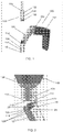
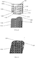
- Figs. 17-19 depict an insertion handle-to-nail snap interface according to yet another exemplary embodiment of the invention.
- the insertion handle 1200 and the nail 1202 also include matching hexalobular geometries, similar to the insertion handle 1100 and nail 1102.
- the insertion handle 1200 is structured to be inserted into the proximal end of the nail 1202.
- the distal end 1204 of the barrel 1208 of the insertion handle 1200 includes a recessed portion 1214 configured and dimensioned to be inserted into and engage an inner surface of the proximal end of the nail 1202.
- the recessed portion 1214 defines a hexalobular shape including six "points" extending radially outward.
- the external surface of the recessed portion 1214 and the internal surface of the nail 1202 are cut into a six-point star-shaped pattern with a plurality of grooves 1217 and protrusions 1219.
- the insertion handle 1200 includes a set of six substantially similar grooves 1217 and six substantially similar protrusions 1219 which alternate about the inner circumference of the channel 1212.
- Each protrusion 1219 corresponds to a "point” on the star-like hexalobular geometry while each groove 1217 corresponds to an indent between each point.
- the internal surface of the nail 1202 includes a set of six substantially similar protrusions 1221 and six substantially similar grooves 1223 which alternate about the inner circumference of the nail 1102.
- Each groove 1223 corresponds to a "point" on the star-like hexalobular geometry while each protrusion 1221 corresponds to an indent between each point.
- five of the points may be rounded while the sixth point, where a flexible beam 1220 is positioned, has a different geometry to promote insertion of the handle 1200 into the nail 1202 in a correct orientation, as will be described in further detail below.
- the grooves 1217, 1223 and protrusions 1219, 1221 of the hexalobular shapes are enlarged (i.e.
- the insertion handle 1200 may also include two parallel longitudinal slots 1218 extending from an outer surface of the handle 1200 to an inner surface thereof and defining a flexible beam 1220 therebetween, similar to beams 920, 1020. As can be seen in the figure, the slots extend proximally from the distal end of the insertion handle 1200, through the recessed portion 1214 and into a non-recessed portion 1216 of the insertion handle 1200.
- a length of the slots 1218 may be chosen depending on the desired range of deflection of the beam 1220. For example, longer slots 1218 provide the beam 1220 with a greater range of deflection while shorter slots 1218 provide the beam 1220 with a smaller range of deflection. In an exemplary embodiment, the slots 1218 may be, for example, approximately (please provide exemplary length of the slots).
- the beam 1220 is able to deflect radially inwardly/outwardly when the distal end 1204 comes into contact with the proximal end of the nail 1202.
- the beam 1220 in this embodiment, further includes an increased thickness flange 1222 extending across the width of the beam 1220 at a distal end thereof.
- the increased thickness flange 1222 is dimensioned to be removably housed within a cavity 1224 on the nail 1202 with a snap-fit engagement.
- the beam 1220 is positioned at one of the rounded outwardly extending points 1215 of recessed portion 1216, creating an asymmetrical shape to prevent the user from inserting the insertion handle 1200 into the nail 1202 in the wrong orientation.
- the beam 1220 is substantially rectangular along a plane that is perpendicular to the longitudinal axis of the insertion handle 1200 so that the insertion handle 1200 can only be inserted into the nail 1202 when the beam 1220 is aligned with a cavity 1228 on the nail 1202.
- each of the six points may include guiding chamfers 1240. That is, the distal edges of each of the six points may include right-angled cut-aways to make a symmetrical sloping edge, facilitating insertion of handle 1200 and reducing nicking damage to both of the components.
- the nail 1202 of this embodiment has an interior surface with a hexalobular geometry matching the external geometry of the recessed portion 1214.
- the inner surface in this embodiment has five rounded portions 1232 and a sixth substantially flat portion 1234 shaped to engage the beam 1220.
- the nail 1202 also includes a cavity 1224 on the flat portion 1234 sized and shaped to removably house the increased thickness flange 1222 of the beam 1220 with a snap-fit engagement creating an audible clicking sound indicating to the user that the insertion handle 1000 and the nail 102 are correctly aligned axially and locked together.
- the beam 1220 snap-fits into the cavity 1224 eliminating the need for a user to manually hold the nail 1202 in place while the connecting screw 150 is inserted into the channel 1212 of the insertion handle 1200.
- the cavity 1236 may extend through the wall of the nail 1202 from the inner surface to the outer surface.
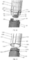
- Figs. 20-21 depict an insertion handle-to-nail snap interface according to yet another exemplary embodiment of the invention.
- the distal free end 1304 of the barrel 1308 of an insertion handle 1300 and the proximal end 1306 of the nail 1302 have matching profiles.
- the distal end 1304 of the insertion handle 1300 includes two opposing convexly rounded portions 1314 separated by two opposing concavely rounded portions 1316.
- the proximal end 1306 of the nail 1302 has two opposing concavely rounded portions 1320 configured to fit with the convex portions 1314 of the insertion handle 1300 and two convexly rounded portions 1322 configured to fit with the concave portions 1316.
- each of the convex portions 1314, 1322 and the concave portions 1316, 1320 of the insertion handle 1300 and the nail 1302 in this embodiment is substantially hemispherical.
- the profiles of the distal end 1304 of the insertion handle 1300 and the proximal end 1306 of the nail 1302 may have any geometry so long as they are configured to fit together. These mating profiles allow the user to easily rotationally align the insertion handle 1300 and the nail 1302 in the correct positions while also aiding in transmitting torque.
- the handle 1300 also includes a recessed portion 1324 extending distally from the distal end 1304 of the barrel 1308 and configured to be inserted into the nail 1302 to engage an inner surface thereof.
- the insertion handle 1300 of this embodiment further includes two parallel longitudinal slots 1326 extending from an outer surface of the handle 1300 to an inner surface thereof and defining a flexible beam 1328 therebetween.
- the slots 1326 extend proximally from the distal end of the insertion handle 1300, through the recessed portion 1324 and into a non-recessed portion 1330 of the insertion handle 1300.
- a length of the slots 1326 may be chosen depending on the desired range of deflection of the beam 1328. As described above, longer slots 1326 provide the beam 1328 with a greater range of deflection while shorter slots 1326 provide the beam 1328 with a smaller range of deflection.
- the slots 1326 may be, for example, approximately 16-18 mm.
- the beam 1328 is able to deflect radially inwardly/outwardly relative to a longitudinal axis of the barrel 1308 when the distal end 1304 comes into contact with the proximal end of the nail 1302.
- the beam 1328 in this embodiment, further includes an increased thickness flange 1332 extending across the width of the beam 1328 at a distal end thereof.
- the increased thickness flange 1332 is dimensioned to be removably housed within a cavity 1334 on the nail 1302 with a snap-fit engagement creating an audible clicking sound indicating to the user that the insertion handle 1300 and the nail 1302 are correctly aligned axially and temporarily locked together.
- the nail 1302 of this embodiment includes the cavity 1334 on an inner surface thereof sized and shaped to removably house the increased thickness flange 1332 of the beam 1328 with a snap-fit engagement creating an audible clicking sound indicating to the user that the insertion handle 1300 and the nail 1302 are correctly aligned axially and locked together.
- the beam 1328 snap-fits into the cavity 1334 eliminating the need for a user to manually hold the nail 1302 in place while a connecting screw 150 is inserted into the channel 1312 of the insertion handle 1300.
- the cavity 1334 may extend through the wall of the nail 1302 from the inner surface to the outer surface.
- the user may disconnect the insertion handle from the nail by exerting a proximal axial force on the insertion handle. This force releases the mating geometries so that the insertion handle may be subsequently removed from the body.
- the user may also wiggle the insertion handle by exerting a lateral back and forth movement to the insertion handle to release the self-retaining mechanism.
- the insertion handles and nails of each of the described embodiments are configured to be locked together using a connecting screw 150 inserted through the channel of the insertion handle and threadedly screwed into a channel within the nail.
- the connecting screw 150 according to the invention includes a head 152 with a driver-engaging recess 154 and an elongated shaft 156 extending distally therefrom, a distal portion thereof including threading 158 configured to threadedly engage threading in the intramedullary nail, as those skilled in the art will understand.
Abstract
Description
- Fractures are often treated with screws or other fixation devices inserted into or through a bone to stabilize fractured portions thereof once they have been brought into corrective alignment. Fixation treatments for long bones often comprise the insertion of an intramedullary nail into a medullary cavity of the bone. Insertion handles enable the user to insert an intramedullary nail into the medullary canal of a bone through a small incision. However, many insertion handle-to-nail interfaces require one user to hold the insertion handle and nail together while someone else locks the two components using, for example, a connecting screw.
- The present invention relates to an implant insertion assembly comprising an insertion handle extending from a proximal end to a distal end, the distal end including a recessed portion, an outer wall of the recessed portion having a first shape about a perimeter thereof and including an engagement mechanism and an implant extending from a distal end to a proximal end including an opening configured to receive the recessed portion of the insertion handle, the opening having a second shape configured to mechanically interlock with the outer wall of the recessed portion when the recessed portion is inserted therein to transmit torque from the insertion handle to the implant, the proximal end including a receiving structure in a wall thereof, the receiving structure being positioned and oriented to receive the engagement mechanism to removably lock the insertion handle to the implant in the axial direction.
- The present invention also relates to an implant insertion assembly for inserting an implant comprising an insertion handle extending from a proximal end to a distal end, the distal end having a shape configured to mate with a proximal end of an implant to which it is to be coupled having a corresponding shape, mechanically interlocking therewith so that, when coupled to an implant, torque is transmitted from the insertion handle to an implant coupled thereto, the distal end including a coupling mechanism configured to engage with the proximal end of an implant to which it is coupled to axially lock the insertion handle to an implant to which it is coupled.
- The present invention also relates to an implant insertion assembly comprising an insertion handle extending from a proximal end to a distal free end and including a channel extending therethrough and two opposing cutouts, a distal surface of the insertion handle including two opposing convexly curved portions positioned between the cutouts and an implant extending from proximal end including an opening to a distal end, the distal end including two proximally extending tabs configured to be inserted into the cutouts, a proximal surface of the implant including two opposing concavely curved portions configured to engage the convexly curved portions of the insertion handle.
-
-
Fig. 1 shows a perspective view of an insertion handle and nail according to an exemplary embodiment of the present disclosure; -
Fig. 2 shows a perspective view of an insertion handle-to-nail interface according to a first exemplary embodiment of the present disclosure; -
Fig. 3 shows a perspective view of an insertion handle-to-nail interface according to a second exemplary embodiment of the present disclosure; -
Fig. 4 shows another perspective view of the insertion handle-to-nail interface of the embodiment ofFig. 3 ; -
Fig. 5 shows a perspective view of an insertion handle-to-nail interface according to a third exemplary embodiment of the present disclosure; -
Fig. 6 shows a perspective view of an insertion handle-to-nail interface according to a fourth exemplary embodiment of the present disclosure; -
Fig. 7 shows a perspective view of an insertion handle-to-nail interface according to a fifth exemplary embodiment of the present disclosure; -
Fig. 8 shows a perspective view of an insertion handle-to-nail interface according to a sixth exemplary embodiment of the present disclosure; -
Fig. 9 shows a perspective view of an insertion handle-to-nail interface according to a seventh exemplary embodiment of the present disclosure; -
Fig 10 shows a top perspective view of the barrel of the insertion handle ofFig. 9 ; -
Fig. 11 shows a cross-sectional view of the barrel of the insertion handle ofFig. 9 ; -
Fig. 12 shows a perspective view of an insertion handle-to-nail interface according to an eighth exemplary embodiment of the present disclosure; -
Fig. 13 shows a perspective view of an insertion handle-to-nail interface according to a ninth exemplary embodiment of the present disclosure; -
Fig. 14 shows a perspective view of an insertion handle-to-nail interface according to a tenth exemplary embodiment of the present disclosure; -
Fig. 15 shows a perspective view of an insertion handle-to-nail interface according to a eleventh exemplary embodiment of the present disclosure; -
Fig. 16 shows a perspective view of an insertion handle-to-nail interface according to a twelfth exemplary embodiment of the present disclosure; -
Fig. 17 shows a perspective view of an insertion handle-to-nail interface according to a thirteenth exemplary embodiment of the present disclosure; -
Fig. 18 shows a side view of the distal end of the insertion handle ofFig. 17 ; -
Fig. 19 shows a top perspective view of the nail ofFig. 17 ; -
Fig. 20 shows a perspective view of an insertion handle-to-nail interface according to a fourteenth exemplary embodiment of the present disclosure; and -
Fig. 21 shows a perspective view of an insertion handle-to-nail interface according to a fifteenth exemplary embodiment of the present disclosure. - The present invention may be further understood with reference to the following description and the appended drawings. The present invention relates generally to devices and methods for fixation and stabilization of inter-trochanteric fractures. It is noted that, although embodiments of the present invention have been described with respect to particular bones, the present invention may also be employed in any of a variety of suitable bone fixation procedures including, but not limited to, the fixation of femoral fractures and fractures of other long bones or any other bone in the body. The present invention relates to an insertion handle for inserting an intramedullary nail into a femur. The exemplary insertion handle according to the invention includes a barrel portion, a free end of which engages a proximal end of the intramedullary nail to guide insertion and orientation thereof relative to the bone. Exemplary embodiments describe a free end of the barrel portion that includes an insertion handle-to-nail interface temporarily retaining a position of the intramedullary nail thereagainst prior to the establishment of a more stable connection between the nail and the insertion handle, for example, via insertion of a connection screw into the handle-to-nail interface. In exemplary embodiments, a snap-fit or "quick-click" connection facilitates nail to handle assembly by a single person which self-retaining connection then permits the same person to finalize the more stable connection. However, those skilled in the art will understand that other coupling mechanisms may be employed without departing from the scope of the invention. The interfaces described herein provide precise assembly and alignment between the nail and the insertion handle. It should be noted that the terms "proximal" and "distal" as used herein refer to a direction toward (proximal) and away from (distal) a user of the device such as a surgeon implanting the nail.
- As shown in
Figs. 1-2 , aninsertion handle 100 according to the invention includes ahandle portion 101 and abarrel portion 108, thebarrel portion 108 extending between aproximal end 103 that is coupled to the handle portion and adistal end 104 configured to be coupled to anintramedullary nail 12. Thedistal end 104 of thebarrel portion 108 includes achannel 112 extending therethrough along an axis which, in an operative position, is substantially aligned with a longitudinal axis of thenail 12 so that a connectingscrew 150 inserted therethrough aligns with an opening 20 extending into a proximal end of theintramedullary nail 12. Thebarrel portion 108 includes atransverse opening 110 angled and dimensioned to receive a tool (not shown) against which a surgeon may hammer to drive anail 12 connected thereto into the bone, as those skilled in the art will understand. - The
distal end 104 of thebarrel portion 108 includes a nail interface configured to preliminarily couple theinsertion handle 100 to theintramedullary nail 12 via a temporary locking arrangement as thedistal end 104 is inserted into the opening 20 in the proximal end of thenail 12. In a first embodiment, shown inFig. 2 , thefree end 104 includes arecess 114 configured and dimensioned to engage atab 116 provided on a proximal end of theintramedullary nail 12. Therecess 114 includes acavity 118 sized and shaped to removably house an increasedthickness flange 120 of thetab 116 with a snap-fit engagement. Thus, when theinsertion handle 100 is positioned over theintramedullary nail 12 in a desired orientation, thetab 116 snap-fits into therecess 114 preliminarily holding thehandle 100 in a desired position and orientation relative to thenail 12 permitting the user to complete the final stable connection between thehandle 100 and thenail 12 without requiring assistance from another person. For example, the preliminary connection allows the user to insert and tighten a connectingscrew 150 in thechannel 112. Thedistal end 104 of thebarrel portion 108 further comprises a substantiallyhemispherical tab 122 sized and shaped for insertion into acorresponding cutout 124 formed in aproximal end 16 of theintramedullary nail 12. A length of thetab 122 in this embodiment is equal to or smaller than a length of thecutout 124. - Turning now to the intramedullary nail, as shown in
Fig. 2 , a first wall portion of aproximal end 16 of theintramedullary nail 12 comprises a pair ofcutouts 126 defining thetab 116 therebetween. A width of thetab 116 is selected to permit deflection thereof within a predetermined range of motion relative to the intramedullary nail 12 (i.e., to permit deflection thereof into the cavity 142). A second side wall of theproximal end 16 of the intramedullary nail located approximately 90° from thetab 116 includes the substantiallyhemispherical cutout 124 sized and shaped to receive the hemispherical tab 144. Thus, thenail 12 and thehandle 100 may be coupled to one another only when rotated relative to one another in a desired alignment. In an exemplary embodiment, theaiming instrument 100 includes onerecess 114 to engage onetab 116. Alternatively, as would be understood by those skilled in the art, any number ofadditional recesses 114 may be provided to engage a corresponding number ofadditional tabs 116. -
Figs. 3-4 show another insertion handle-to-nail interface according to another exemplary embodiment of the present invention. In this embodiment, adistal end 204 of thebarrel 208 of theinsertion handle 200 includes fourrigid tabs tabs distal end 204 of theinsertion handle 200 and each is sized and shaped for insertion intocorresponding cutout proximal end 26 of theintramedullary nail 22. In an exemplary embodiment, thetabs tabs corresponding cutout opposing tabs tabs 214, 218) on lateral sides thereof. Thetabs opposing cutouts intramedullary nail 22 formed betweenflexible cantilever beams 232 such that theundercuts 230 removably house a distal end of thecantilever beams 232 with a snap-fit engagement, as discussed in further detail below. Thus, when theinsertion handle 200 is positioned over theintramedullary nail 22 in a desired orientation, the distal ends of the cantilever beams 232 snap fit into theundercuts 230 of thetabs intramedullary nail 22 in place while the connectingscrew 150 is inserted into the channel 212. - Turning to the proximal end of the
intramedullary nail 22, as shown inFig. 3 , a first pair ofslots 234 and the substantiallyhemispherical cutout 222 define a first pair ofcantilever beams 232 therebetween. Theslots 234 andcutouts 222 extend through the wall of thenail 22 from a radially outer surface to a radially inner surface thereof. A width of each of thebeams 232 is selected to permit lateral deflection thereof within a predetermined range of motion when thecorresponding tab 214 is inserted into thecutout 222. Proximal ends 236 of thebeams 232 are configured to fit within theundercuts 230 of thetab 214. A second pair ofslots 238 and the substantiallyhemispherical cutout 226 define a second pair ofcantilever beams 240 located approximately 180 degrees from the first pair of cantilever beams 232. Again, a width of thebeams 240 is selected to permit lateral deflection thereof within a predetermined range of motion when thecorresponding tab 218 is inserted into thecutout 226. When thetabs cutouts 222 226, the proximal ends of thebeams undercuts 230, causing an audible clicking noise. This clicking sound serves as audible confirmation of correct assembly between theinsertion handle 200 and thenail 22. Theproximal end 26 also includes two further substantiallyhemispherical cutouts cutouts cutouts nail 22 or completely therethrough. Thus, thetabs tabs tabs corresponding cutouts nail 22. Specifically, thenail 22 and theinsertion handle 200 may be coupled together only when rotated to a desired alignment (i.e., with each of thetabs corresponding cutout intramedullary nail 22 includes four recesses to engage the four tabs of the insertion handle, which enables torque to be easily transmitted from the insertion handle 200 to thenail 22. However, it will be understood that any number of recesses may be provided to engage a corresponding number of tabs. - An insertion handle-to-nail interface according to another exemplary embodiment is shown in
Fig. 5 . Specifically, thefree end 304 of abarrel 308 of aninsertion handle 300 includes atab 314 extending distally therefrom sized and shaped for insertion into acorresponding cutout 316 formed in aproximal end 36 of theintramedullary nail 32. A length of thetab 314 in this embodiment is equal to or smaller than the length of thecutout 316. In an exemplary embodiment, theinsertion handle 300 may include two opposingtabs 314 separated from one another by approximately 180 degrees. Thetabs 314 allow for easy rotational alignment of theinsertion handle 300 and theintramedullary nail 32 by the user. Theinsertion handle 300, in this embodiment, also includes aninternal ridge 316 extending circumferentially about an inner surface of theopening 308. Theridge 316 may be, for example, a raised band on the inner surface extending about the circumference of thechannel 312. Theridge 316 is configured and dimensioned to engage a circumferential recessedportion 318 on the proximal end of theintramedullary nail 32. For example, theridge 316 is sized and shaped to fit within agroove 320 extending about the circumference of the recessedportion 318, creating a snap-fit or quick-click engagement. Thus, when theinsertion handle 300 is positioned over theintramedullary nail 32 in a desired orientation, theridge 316 snap-fits into thegroove 320 eliminating the need for a user to manually hold theintramedullary nail 32 in place while the connectingscrew 150 is inserted into thechannel 312. - Turning to the
intramedullary nail 32, as shown inFig. 5 , theproximal end 36 includes a recessedportion 318, described above, which extends about the circumference of theproximal end 36. The recessedportion 318 is configured and dimensioned to fit within thechannel 312 and engage the inner surface thereof. More specifically, as described above, agroove 320 extending along the recessedportion 318 is sized to engage theridge 316 provided on the inner surface. In an exemplary embodiment, rather than the recessedportion 318 extending about the entire circumference of thenail 32, theproximal end 36 may include a plurality ofslots 322 defining separate recessedtabs 324 therebetween. Each of thetabs 324 of this exemplary embodiment also includes agroove 320 configured to engage theridge 316. Thetabs 324, in this embodiment, allow for deflection thereof within a predetermined range of motion relative to the insertion handle 300 (i.e., to permit deflection thereof into thechannel 312 to receive theridge 316 within thegroove 320. When thegroove 320 engages with theridge 316 of theinsertion handle 300, an audible clicking noise is audible serving as confirmation of correct assembly between theinsertion handle 300 and thenail 32. -
Fig. 6 depicts an insertion handle-to-nail interface according to yet another embodiment of the invention. In this embodiment, thefree end 404 of thebarrel 408 of aninsertion handle 400 includes agroove 414 extending about a circumference of an inner surface of thechannel 412 and configured to engage aflange 416 on theproximal end 46 of anail 42. In another exemplary embodiment, theinsertion handle 400 includes an increased thickness ridge instead of a groove extending about the circumference of thechannel 412 and configured to engage theflange 416 when it is inserted distally therepast. - The
intramedullary nail 42 of this embodiment includes a flexible recessedportion 418 extending proximally past aproximal end 46 of thenail 42. The flexible recessedportion 418 extends about the entire circumference of theproximal end 46 of the nail and has a thickness that allows the recessedportion 418 to deflect radially inwardly toward a center axis, L, of thenail 42 and outwardly away from a center axis of thenail 42. Thus, a thickness of thewall 420 of the recessedportion 418 is sufficiently thin to permit it to flex without plastic deformation. The recessedportion 418 includes an increaseddiameter flange 416, as described above, disposed about a proximal tip. Theflange 416 may extend about the entire circumference of the outer surface of the recessedportion 418 or may only be positioned on lateral sides thereof. Theflange 416 is configured to be removably housed within thegroove 414 via a snap-fit engagement, creating an audible clicking sound signaling to the user that theintramedullary nail 42 and insertion handle 400 are axially locked to one another. Aninner surface 422 of the recessedportion 418 is milled to a substantially conical shape. Specifically, a diameter of theopening 20 at the proximal end of recessedportion 418 is larger than a diameter of theopening 20 at a distal end of the recessedportion 418, as can be seen in the figure. Thus, once theflange 416 is snap-fit into thegroove 414, thescrew 150 may be inserted through thechannel 412 into the conical portion of theopening 20 such that an outer surface of thescrew 150 pushes theflange 416 outward circumferentially, securing the connection between thenail 42 and theinsertion handle 400 for further clinical steps. -
Fig. 7 depicts an insertion handle-to-nail interface according to yet another embodiment of the invention. In this embodiment, thefree end 504 of thebarrel 508 of aninsertion handle 500 includes a spring-locking mechanism. Specifically, thefree end 504 of theinsertion handle 500 includes two recessedportions 514 configured to engage an inner surface of theproximal end 56 of theintramedullary nail 52. Positioned between the two recessedportions 514 are twonon-recessed portions 516 configured to engage twocutouts 518 in the outer surface of theintramedullary nail 52. Thenon-recessed portions 516 taper distally so that they are substantially trapezoidal in shape, as can be seen in the figure, and have a width that is equal to or slightly smaller than the width of thecutouts 518. Thenon-recessed portions 516 allow the user to easily rotationally align the insertion handle 500 with theintramedullary nail 52 as well as provide torque and rotation transmission from the insertion handle 500 to thenail 52 when the two components are coupled together. The insertion handle 500 may further include a plurality oftabs 520 extending distally from the recessedportions 514. In an exemplary embodiment, there are fourflexible tabs 520 distributed evenly around the circumference of thefree end 504. However, it will be understood that any number of tabs may be used. Each of thetabs 520 includes an increasedthickness ridge 522 extending radially outward along the width of thetab 520 and sized and shaped to removably engage acircumferential ridge 524 on in the inner surface of theintramedullary nail 52 with a snap-fit or quick click engagement. A width of each of thetabs 520 is selected to permit radial deflection thereof within a predetermined range of motion (i.e., to permit deflection thereof when passing theridge 524 of the nail 52). - The
intramedullary nail 52 of this embodiment, as described above, comprises a pair ofcutouts 518 extending from an outer surface of theintramedullary nail 52 to an inner surface thereof. Thecutouts 518 taper distally to adistal wall 526, defining a substantially trapezoidal shape corresponding to the trapezoidalnon-recessed portions 516. Theintramedullary nail 52 also includes arounded ridge 524 extending about the circumference of an inner surface of theproximal end 56. Theridge 524 is configured to engage a proximal surface of theridge 522 on thetabs 520. That is, when theinsertion handle 500 is inserted into theintramedullary nail 52, theridge 524 causes thetabs 520 on the insertion handle 500 to deform towards the center axis of theinsertion handle 500. As theinsertion handle 500 is pushed further distally into thenail 52 and theridge 522 moves distally past theridge 524 on thenail 52 and thetabs 520 snap back outwardly, in a direction away from a central, longitudinal axis L of theinsertion handle 500, creating an audible clicking sound. Thus, the engagement of the tworidges insertion handle 500 andnail 52 in a temporary locking arrangement. In another exemplary embodiment, instead of a ridge, thenail 52 may have a groove extending about a circumference of the inner surface thereof configured to removably house theridge 522 of the insertion handle 500 therein with a snap-fit engagement. - In an exemplary embodiment, depicted in
Fig. 8 , in lieu of tabs, thenon-recessed portions 516 are configured for a friction-fit interface between theinsertion handle 500 and thenail 52. Specifically, theinsertion handle 500 includes aslot 530 extending longitudinally through each of thenon-recessed portions 516 from an outer surface of the insertion handle 500 to an inner surface thereof, defining twoflexible members 532. Theflexible members 532 are deflectable laterally within a predetermined range of motion- i.e., theflexible members 532 are deflected toward one another into theslot 530 when inserted into thecutouts 518. In this embodiment, the width of thenon-recessed portions 516, including theslots 530, is larger than the width of thecutouts 518 in thenail 52. Thus, thecutouts 518 force theflexible members 532, which are biased toward a separated position, to flex toward one another when inserted therein, so that theflexible members 532 project an outward lateral force against the side walls of thecutouts 518, holding theinsertion handle 500 and thenail 52 together via friction fit. -
Figs. 9-11 depict a friction fit insertion handle-to-nail interface according to another exemplary embodiment of the invention. In this embodiment, thedistal end 604 of thebarrel 608 of theinsertion handle 600 includes two opposingrigid tabs 614 extending distally therefrom. Thetabs 614 are separated by approximately 180 degrees and are sized and shaped for insertion into two correspondingcutouts 616 formed in theproximal end 66 of thenail 62. Thetabs 614 taper distally so that they are substantially trapezoidal in shape, as can be seen in the figure, and have a width that is equal to or slightly larger than the width of thecutouts 616 so as to hold theinsertion handle 600 and thenail 62 together by friction fit. Thetabs 614 allow the user to easily rotationally align the insertion handle 600 with theintramedullary nail 62 as well as provide torque and rotation transmission from the insertion handle 600 to thenail 62 when the two components are coupled together. - The
intramedullary nail 62 of this embodiment, comprises a pair of recessedportions 618 separated by thecutouts 616. The recessedportions 618 are configured to fit within thechannel 612 of theinsertion handle 600. Thecutouts 616 extend from an outer surface of theintramedullary nail 62 to an inner surface thereof. Thecutouts 616 taper distally to adistal wall 620, defining a substantially trapezoidal shape corresponding to thetrapezoidal tabs 614. Thus, insertion of thetabs 614 into thecutouts 616 rotationally lock theinsertion handle 600 andnail 62. In this embodiment, thescrew 150, when inserted through thechannel 612 and threadedly screwed into thenail 62, axially fixes the insertion handle 600 to thenail 62. This tightening of thescrew 150 into thenail 62 also further presses thetabs 614 into thecutouts 616. The interface of this embodiment further includes aclip 622 which keeps thescrew 150 in place when assembling the connection between thenail 62 and thehandle 600. Theclip 622 includes twoarms rounded connection portion 628 to substantially form a U-shape. Thefirst arm 624 is straight and sized and shaped to be inserted through atransverse hole 628 open to thebarrel 608. Thesecond arm 626 includes a rounded portion configured to conform to the shape of a lateral outer surface of thebarrel 608. Theclip 622 is biased to pinch closed pressing thescrew 150 against an interior surface of thechannel 612 generating friction that maintains thescrew 150 in place while the handle and nail are coupled to one another. -
Fig. 12 depicts a friction fit insertion handle-to-nail interface according to yet another exemplary embodiment of the invention. In this embodiment, thedistal end 704 of thebarrel 708 of theinsertion handle 700 includes two opposingrigid tabs 714 extending distally therefrom. Thetabs 714 are separated by approximately 180 degrees and are sized and shaped for insertion into correspondingcutouts 716 formed in theproximal end 76 of thenail 72. Each of thetabs 714 is substantially rectangular and has a length equal to or smaller than a length of thecutout 716. - The
intramedullary nail 72 of this embodiment, as described above, includes two substantiallyrectangular cutouts 716 substantially corresponding to the shape of thetabs 714. Thenail 72 also includes twoslots 718, each positioned adjacent to thecutouts 716 to define two flexible cantilever beams 720. A width of each of thebeams 720 is selected to permit lateral deflection thereof within a predetermined range of motion when thecorresponding tab 714 is inserted into thecutout 716. A width of each of thecutouts 716 is slightly smaller than a width of each of thetabs 714 so that theinsertion handle 700 and thenail 72 are held together via friction. Thetabs 714 and theircorresponding cutouts 716 help the user correctly align the insertion handle 700 with thenail 72. Specifically, thenail 72 and theinsertion handle 700 may be coupled only when rotated to a desired alignment (i.e., with each of thetabs 714 aligned with a corresponding one of the cutouts 716). In this exemplary embodiment, theintramedullary nail 72 includes twocutouts 716, each engaging a corresponding one of the twotabs 714 of theinsertion handle 700, which enables torque to be easily transmitted from the insertion handle 700 to thenail 72. As would be understood by those skilled in the art, any number of cutouts may be provided to engage a corresponding number of tabs. In an exemplary embodiment, proximal ends 722 of thebeams 720 may also include anengagement mechanism 724 such as, for example, a ridge or a groove on a lateral surface facing thecutouts 716 configured to engage with a corresponding engagement mechanism 726 (i.e., a ridge or groove) on the lateral opposing surface of thetabs 714. As those skilled in the art will understand, any of the various arrangements of mating pairs of tabs and cutouts may be mixed and matched as desired or the dimensions of the various tabs and cutouts may be varied so that the nail and the handle will mate in only a single desired rotational alignment. When thetabs 714 are inserted into thecutouts 716 the proximal ends 722 of thebeams 720 deflect into theengagement mechanism 726 on thecutouts 716. -
Fig. 13 depicts an insertion handle-to-nail snap interface according to yet another exemplary embodiment of the invention. In this embodiment, the distalfree end 804 of thebarrel 808 of aninsertion handle 800 and theproximal end 86 of thenail 82 have matching profiles. Specifically, thedistal end 804 of theinsertion handle 800 includes two opposing convexlyrounded portions 814 while theproximal end 86 of thenail 82 has two opposing concavelyrounded portions 816 configured to fit with theconvex portions 814. Both theconvex portions 814 and theconcave portions 816, in this embodiment, are substantially hemispherical. However, it will be understood that the profiles of thedistal end 804 of theinsertion handle 800 and theproximal end 86 of thenail 82 may have any geometry so long as they are configured to fit together. These mating profiles allow the user to easily rotationally align theinsertion handle 800 and thenail 82 in the correct positions while also aiding in transmitting torque from thehandle 800 to thenail 82. Looking to theinsertion handle 800, thedistal end 804 further includes two rounded opposingcutouts 818 positioned between theconvex portions 814 and extending from an outer surface of the insertion handle 800 to an inner surface thereof. Thecutouts 818 in this embodiment are substantially circular and open to thedistal end 804. Thecutouts 818 are configured and dimensioned to receivetabs 820 provided on a proximal end of thenail 82. Aneck portion 824 of thecutouts 818 has a width smaller than a diameter of the tabs, providing a temporary snap-connection, as described in further detail below. The insertion handle 800 further includes two distally-extendingtabs 822 positioned at the distal-most point of theconvex portions 814. Thus, thetabs 822 are separated from thecutouts 818 by approximately 90 degrees. Thetabs 822 may be, in this embodiment, substantially rectangular and are sized and shaped for insertion in twocorresponding cutouts 825. - The
intramedullary nail 82 of this embodiment includes two substantiallycircular tabs 820 extending from a proximal end thereof. Each of thetabs 820 includes alongitudinally extending slot 826 open to the proximal end of thetabs 820 which bisects thetab 820 into twoflexible members 828. Each of thetabs 820 has a diameter larger than that of theneck portion 824 of the correspondingcutouts 818 and is configured to be removably housed within thecutout 818 with a snap-fit engagement. Thus, when theinsertion handle 800 is positioned over theintramedullary nail 82 in a desired orientation, thetabs 820 snap fit into thecutouts 818. Specifically, theflexible members 828, when they come into contact with theneck portion 824, deflect radially inward to pass through theneck portion 824. When theflexible members 828 pass through theneck portion 824, they snap away from each other, temporarily locking thetabs 820 within thecutouts 818 with an audible clicking noise. Thedistal end 804 of thenail 82 further comprises twocutouts 825 extending from an outer surface at least partially through the wall of thenail 82. Thecutouts 825 are sized and dimensioned to engage thetabs 822 and have a substantially rectangular profile. Thus, thenail 82 and theinsertion handle 800 may be coupled only when rotated to a desired alignment. Thetabs 824, when inserted into thecutouts 825, provide increased torque transmission from the insertion handle 800 to thenail 82. -
Fig. 14 depicts an insertion handle-to-nail snap interface according to yet another exemplary embodiment of the invention. In this embodiment, a distalfree end 904 of thebarrel 908 of aninsertion handle 900 includes two opposingrounded cutouts 914 configured and dimensioned to engage two opposingtabs 916 provided on aproximal end 96 of anintramedullary nail 92. In the insertion handle 900 ofFig. 14 , thecutouts 914 are shown to be substantially circular, similar to thecutouts 818. However, it will be understood that thecutouts 914 may be any shape, so long as the profiles fit with the profiles of thetabs 916. The insertion handle 900 further includes a pair ofparallel slots 918 extending longitudinally along thedistal end 904 of thehandle 92 and defining aflexible beam 920 therebetween. Theslots 918 extend from the outer surface of the insertion handle 900 to an inner surface thereof. A length of each of theslots 918 may be chosen depending on the desired range of deflection of thebeam 920. For example as would be understood by those skilled in the art,longer slots 918 provide thebeam 920 with a greater range of deflection whileshorter slots 918 provide thebeam 920 with a smaller range of deflection. In an exemplary embodiment, theslots 918 may be, for example, approximately 16-18 mm. In an exemplary embodiment, theinsertion handle 900 includes two pairs ofslots 918 defining a pair of opposingbeams 920. In this embodiment, thebeams 920 may be separated by approximately 180 degrees. Thebeams 920 each include atab 922 extending from a distal end thereof and configured to engage an inner surface of thenail 92 with a snap-fit engagement. For example, each of thetabs 922 may include amating feature 924 such as a groove or an undercut extending across the width of each of thetabs 922. Each of the mating features 924, in this embodiment, is sized and shaped to engage acorresponding mating feature 926 on a radially inner surface of thenail 92 via a snap-fit or quick-click engagement. In an exemplary embodiment, the insertion handle 900 further includes a supportingring 928 extending about at least a portion of the circumference of thedistal end 904, as shown inFig. 14 . The supportingring 928 provides further support to thebeams 920 and thedistal end 904 of thehandle 900 when thehandle 900 is coupled to thenail 92. - A
proximal end 96 of theintramedullary nail 92 of this embodiment includes the twotabs 916 extending proximally therefrom each of which is configured to fit within a corresponding one of thecutouts 914. Thetabs 916 shown inFig. 14 are substantially rectangular. However, it will be understood that thetabs 916 may take any shape so long as they fit within thecutouts 914 of theinsertion handle 900. As with previous embodiments, thetabs 916 and thecutouts 914 allow the user to easily align the insertion handle 900 with thenail 92 in the correct orientation while also provide increased torque and rotation transmission from the insertion handle 900 to thenail 92. Thenail 92 further includes thecircumferential mating feature 926 along the inner surface thereof. Themating feature 926 in this embodiment is a circumferential increased thickness ridge that engages themating feature 924 on thetabs 922 of theinsertion handle 900. For example, when theinsertion handle 900 is inserted into the proximal end of thenail 92, thebeams 920 with thetabs 922 may deflect inwardly (toward the central axis of the insertion handle) when thetabs 922 contact an increased thickness portion of the interior surface of the nail 92 - i.e., a ridge. However, because thetabs 922 include a mating feature such as a groove or an undercut, as theinsertion handle 900 is moved further distally into thenail 92, the ridge will fit within the groove and thetabs 922 will snap back outwardly (away from the central axis of the insertion handle), temporarily locking the two components together and creating an audible clicking noise. This allows the user to know that theinsertion handle 900 and thenail 92 are axially coupled correctly. In this embodiment, thescrew 150 may provide further support to the connection when inserted into the channel 912. Specifically, the outer surface of thescrew 150 exerts a radially outwardly directed force on the interior of theinsertion handle 900, pressing thebeams 920 and thetabs 922 into the inner surface of thenail 92 and preventing the mating features 924 of the insertion handle 900 from deflecting out of or away from the mating features 926 of thenail 92. -
Fig. 15 depicts an insertion handle-to-nail snap interface according to yet another exemplary embodiment of the invention. In this embodiment, the interior geometry of aninsertion handle 1000 is configured to match the exterior geometry of thenail 102. Specifically, in this embodiment, adistal portion 1014 the inner surface of theinsertion handle 100 is cut to define a substantially hexagonal shape, as seen inFig. 15 . Similarly, a proximal recessedportion 1016 of the outer surface of thenail 102 is cut to define a substantially hexagonal shape. Thus, the matching hexagonal geometries on thenail 102 and theinsertion handle 1000 facilitate easier insertion by the user in a correct orientation, as well as increased torque transmission from theinsertion handle 1000 to thenail 102. Turning to theinsertion handle 1000, thedistal end 1004 of thebarrel 1008 according to this embodiment also includes two substantially parallellongitudinal slots 1018 extending from an outer surface of thehandle 1000 to an inner surface thereof and defining aflexible beam 1020 therebetween, similar tobeams 920 ofinsertion handle 900. A length of theslots 1018 may be chosen depending on the desired range of deflection of thebeam 1020. As indicated above,longer slots 1018 provide thebeam 1020 with a greater range of deflection whileshorter slots 1018 provide thebeam 1020 with a smaller range of deflection. In an exemplary embodiment, theslots 1018 may be, for example, approximately 16-18 mm. Thebeam 1020 deflects radially inwardly/outwardly when thedistal end 1004 comes into contact with the proximal end of thenail 102. Thebeam 1020, in this embodiment, further includes an increasedthickness ridge 1022 extending across the width of thebeam 1020 at a distal end thereof. Theridge 1022 is dimensioned to be removably housed within arecess 1024 on thenail 102 with a snap-fit engagement. In an embodiment, thebeam 1020 may further includelongitudinal ridges 1026 positioned at the lateral portions of the inner surface thereof. Theridges 1026 are configured to fit withinlongitudinal grooves 1028 on one of the faces of the hexagonal outer surface of thenail 102. Thebeam 1020 is centrally positioned on one of the sides of the hexagonal profile of theinsertion handle 1000 while thegrooves 1028 are positioned on a corresponding side of the hexagonal profile of thenail 102. Thus, one face 1030 of the hexagonal geometries of both thehandle 1000 and thenail 102 differs from the rest, creating an asymmetrical geometry therein that prevents the user from inserting thenail 102 within theinsertion handle 1000 in an incorrect orientation. Therefore, thenail 102 and theinsertion handle 1000 may be coupled only when rotated to a desired alignment. - The
nail 102 of the present embodiment, as described above, has a proximal recessedportion 1016 with a hexagonal geometry and acircumferential groove 1024 disposed distally of the proximal recessedportion 1016. Thegrooved portion 1024 of thenail 102 is substantially cylindrical with a diameter smaller than a diameter of the remainder of thenail 102, including the proximal portion 1032. Thegroove 1024 is sized and shaped to removably house theridge 1022 on the distal end of thebeam 1020 with a snap-fit engagement, creating an audible clicking sound indicating to the user that theinsertion handle 1000 and thenail 102 are correctly aligned axially and locked together. - In another exemplary embodiment shown in
Fig. 16 , aninsertion handle 1100 and anail 1102 have substantially the same structure as theinsertion handle 1000 andnail 102. However, in this embodiment, the internal geometry of theinsertion handle 1100, as well as the external geometry of thenail 1102 are substantially hexalobular. Specifically, the internal surface of theinsertion handle 1100 and the external surface of thenail 110 are cut into a six-point star-shaped pattern with a plurality ofgrooves 1117 andprotrusions 1119. Theinsertion handle 1100 includes a set of six substantiallysimilar grooves 1117 and six substantiallysimilar protrusions 1119 which alternate about the inner circumference of the channel 1112. Eachgroove 1117 corresponds to a "point" on the star-like hexalobular geometry while eachprotrusion 1119 corresponds to an indentation between each point. In the embodiment ofFig. 16 , thebeam 1120 of the insertion handle is positioned at one of the "points" so that that point is flatter, or less rounded, than the remaining five points. Similarly, a recessed portion 1116 of thenail 1102 includes a set of six substantiallysimilar protrusions 1121 and six substantiallysimilar grooves 1123 which alternate about the outer circumference of thenail 1102. Eachprotrusion 1121 corresponds to an indent on the star-like hexalobular geometry while eachprotrusion 1223 corresponds to a point. However, one of the protrusions of the nail may be substantially flat to enable engagement of the proximal recessed portion 1116 with thebeam 1120. In an exemplary embodiment, thegrooves protrusions -
Figs. 17-19 depict an insertion handle-to-nail snap interface according to yet another exemplary embodiment of the invention. In this embodiment, theinsertion handle 1200 and thenail 1202 also include matching hexalobular geometries, similar to theinsertion handle 1100 andnail 1102. However, in this embodiment theinsertion handle 1200 is structured to be inserted into the proximal end of thenail 1202. Specifically, thedistal end 1204 of thebarrel 1208 of theinsertion handle 1200 includes a recessedportion 1214 configured and dimensioned to be inserted into and engage an inner surface of the proximal end of thenail 1202. As can be seen in the figures, the recessedportion 1214 defines a hexalobular shape including six "points" extending radially outward. Specifically, the external surface of the recessedportion 1214 and the internal surface of thenail 1202 are cut into a six-point star-shaped pattern with a plurality ofgrooves 1217 andprotrusions 1219. Theinsertion handle 1200 includes a set of six substantiallysimilar grooves 1217 and six substantiallysimilar protrusions 1219 which alternate about the inner circumference of the channel 1212. Eachprotrusion 1219 corresponds to a "point" on the star-like hexalobular geometry while eachgroove 1217 corresponds to an indent between each point. Similarly, the internal surface of thenail 1202 includes a set of six substantiallysimilar protrusions 1221 and six substantiallysimilar grooves 1223 which alternate about the inner circumference of thenail 1102. Eachgroove 1223 corresponds to a "point" on the star-like hexalobular geometry while eachprotrusion 1221 corresponds to an indent between each point. In this embodiment, five of the points may be rounded while the sixth point, where aflexible beam 1220 is positioned, has a different geometry to promote insertion of thehandle 1200 into thenail 1202 in a correct orientation, as will be described in further detail below. In an exemplary embodiment, thegrooves protrusions grooves protrusions insertion handle 1200 may also include two parallellongitudinal slots 1218 extending from an outer surface of thehandle 1200 to an inner surface thereof and defining aflexible beam 1220 therebetween, similar tobeams insertion handle 1200, through the recessedportion 1214 and into anon-recessed portion 1216 of theinsertion handle 1200. A length of theslots 1218 may be chosen depending on the desired range of deflection of thebeam 1220. For example,longer slots 1218 provide thebeam 1220 with a greater range of deflection whileshorter slots 1218 provide thebeam 1220 with a smaller range of deflection. In an exemplary embodiment, theslots 1218 may be, for example, approximately (please provide exemplary length of the slots). Thebeam 1220 is able to deflect radially inwardly/outwardly when thedistal end 1204 comes into contact with the proximal end of thenail 1202. Thebeam 1220, in this embodiment, further includes an increasedthickness flange 1222 extending across the width of thebeam 1220 at a distal end thereof. The increasedthickness flange 1222 is dimensioned to be removably housed within acavity 1224 on thenail 1202 with a snap-fit engagement. Thebeam 1220 is positioned at one of the rounded outwardly extending points 1215 of recessedportion 1216, creating an asymmetrical shape to prevent the user from inserting theinsertion handle 1200 into thenail 1202 in the wrong orientation. Specifically, thebeam 1220 is substantially rectangular along a plane that is perpendicular to the longitudinal axis of theinsertion handle 1200 so that theinsertion handle 1200 can only be inserted into thenail 1202 when thebeam 1220 is aligned with a cavity 1228 on thenail 1202. In an exemplary embodiment, each of the six points may include guidingchamfers 1240. That is, the distal edges of each of the six points may include right-angled cut-aways to make a symmetrical sloping edge, facilitating insertion ofhandle 1200 and reducing nicking damage to both of the components. - The
nail 1202 of this embodiment, as described above has an interior surface with a hexalobular geometry matching the external geometry of the recessedportion 1214. Specifically, the inner surface in this embodiment has five rounded portions 1232 and a sixth substantially flat portion 1234 shaped to engage thebeam 1220. Thenail 1202 also includes acavity 1224 on the flat portion 1234 sized and shaped to removably house the increasedthickness flange 1222 of thebeam 1220 with a snap-fit engagement creating an audible clicking sound indicating to the user that theinsertion handle 1000 and thenail 102 are correctly aligned axially and locked together. Thus, when theinsertion handle 1200 is positioned over thenail 1202 in a desired orientation, thebeam 1220 snap-fits into thecavity 1224 eliminating the need for a user to manually hold thenail 1202 in place while the connectingscrew 150 is inserted into the channel 1212 of theinsertion handle 1200. In another embodiment, shown inFig. 17 , the cavity 1236 may extend through the wall of thenail 1202 from the inner surface to the outer surface. -
Figs. 20-21 depict an insertion handle-to-nail snap interface according to yet another exemplary embodiment of the invention. In this embodiment, the distalfree end 1304 of thebarrel 1308 of aninsertion handle 1300 and theproximal end 1306 of thenail 1302 have matching profiles. Specifically, thedistal end 1304 of theinsertion handle 1300 includes two opposing convexlyrounded portions 1314 separated by two opposing concavelyrounded portions 1316. Similarly, theproximal end 1306 of thenail 1302 has two opposing concavelyrounded portions 1320 configured to fit with theconvex portions 1314 of theinsertion handle 1300 and two convexlyrounded portions 1322 configured to fit with theconcave portions 1316. Each of theconvex portions concave portions insertion handle 1300 and thenail 1302 in this embodiment, is substantially hemispherical. However, it will be understood that the profiles of thedistal end 1304 of theinsertion handle 1300 and theproximal end 1306 of thenail 1302 may have any geometry so long as they are configured to fit together. These mating profiles allow the user to easily rotationally align theinsertion handle 1300 and thenail 1302 in the correct positions while also aiding in transmitting torque. Looking to theinsertion handle 1300, thehandle 1300 also includes a recessed portion 1324 extending distally from thedistal end 1304 of thebarrel 1308 and configured to be inserted into thenail 1302 to engage an inner surface thereof. The insertion handle 1300 of this embodiment further includes two parallellongitudinal slots 1326 extending from an outer surface of thehandle 1300 to an inner surface thereof and defining aflexible beam 1328 therebetween. As can be seen in the figure, theslots 1326 extend proximally from the distal end of theinsertion handle 1300, through the recessed portion 1324 and into a non-recessed portion 1330 of theinsertion handle 1300. A length of theslots 1326 may be chosen depending on the desired range of deflection of thebeam 1328. As described above,longer slots 1326 provide thebeam 1328 with a greater range of deflection whileshorter slots 1326 provide thebeam 1328 with a smaller range of deflection. In an exemplary embodiment, theslots 1326 may be, for example, approximately 16-18 mm. Thebeam 1328 is able to deflect radially inwardly/outwardly relative to a longitudinal axis of thebarrel 1308 when thedistal end 1304 comes into contact with the proximal end of thenail 1302. Thebeam 1328, in this embodiment, further includes an increasedthickness flange 1332 extending across the width of thebeam 1328 at a distal end thereof. The increasedthickness flange 1332 is dimensioned to be removably housed within acavity 1334 on thenail 1302 with a snap-fit engagement creating an audible clicking sound indicating to the user that theinsertion handle 1300 and thenail 1302 are correctly aligned axially and temporarily locked together. - The
nail 1302 of this embodiment, as described above, includes thecavity 1334 on an inner surface thereof sized and shaped to removably house the increasedthickness flange 1332 of thebeam 1328 with a snap-fit engagement creating an audible clicking sound indicating to the user that theinsertion handle 1300 and thenail 1302 are correctly aligned axially and locked together. Thus, when theinsertion handle 1300 is positioned over thenail 1302 in a desired orientation, thebeam 1328 snap-fits into thecavity 1334 eliminating the need for a user to manually hold thenail 1302 in place while a connectingscrew 150 is inserted into thechannel 1312 of theinsertion handle 1300. In another embodiment, thecavity 1334 may extend through the wall of thenail 1302 from the inner surface to the outer surface. - In use, once the intramedullary nail is placed in a desired position within the bone, the user may disconnect the insertion handle from the nail by exerting a proximal axial force on the insertion handle. This force releases the mating geometries so that the insertion handle may be subsequently removed from the body. In some embodiments, the user may also wiggle the insertion handle by exerting a lateral back and forth movement to the insertion handle to release the self-retaining mechanism.
- It will be understood by those skilled in the art that the insertion handles and nails of each of the described embodiments are configured to be locked together using a connecting
screw 150 inserted through the channel of the insertion handle and threadedly screwed into a channel within the nail. The connectingscrew 150 according to the invention includes ahead 152 with a driver-engagingrecess 154 and anelongated shaft 156 extending distally therefrom, a distal portion thereof including threading 158 configured to threadedly engage threading in the intramedullary nail, as those skilled in the art will understand. - It will be understood by those of skill in the art that modifications and variations may be made in the structure and methodology of the present invention, without departing from the spirit or the scope of the invention. Thus, it is intended that the present invention cover the modifications and variations of this invention, provided that they come within the scope of the appended claims and their equivalents.
Preferred embodiments of the invention are described in the following numbered paras 1 to 20: - 1. An implant insertion assembly, comprising:
- an insertion handle extending from a proximal end to a distal end, the distal end including a recessed portion, an outer wall of the recessed portion having a first shape about a perimeter thereof and including an engagement mechanism; and
- an implant extending from a distal end to a proximal end including an opening configured to receive the recessed portion of the insertion handle, the opening having a second shape configured to mechanically interlock with the outer wall of the recessed portion when the recessed portion is inserted therein to transmit torque from the insertion handle to the implant, the proximal end including a receiving structure in a wall thereof, the receiving structure being positioned and oriented to receive the engagement mechanism to removably lock the insertion handle to the implant in the axial direction.
- 2. The assembly of para 1, wherein the engagement mechanism is an increased thickness flange and the receiving structure is a transverse cavity sized to receive the flange.
- 3. The assembly of para 2, wherein the insertion handle further comprises a pair of longitudinal slots extending through a wall of the insertion handle from an outer surface to an inner surface thereof, the slots defining a flexible beam therebetween configured to radially deflect within a predetermined range of motion when inserted into the implant.
- 4. The assembly of para 3, wherein the slots extend proximally from an open distal end at a distal surface of the insertion handle to a proximal end positioned proximally of the recessed portion.
- 5. The assembly of para 3, wherein the first shape is substantially hexalobular comprising six radially outwardly extending protrusions and six radially inwardly extending grooves alternating about the circumference of the recessed portion, wherein one of the protrusions comprises the flexible beam, and wherein the second shape is substantially hexalobular comprising five radially outwardly extending grooves and six radially inwardly extending protrusions alternating about a circumference of the opening, two of the protrusions being separated by a substantially flat portion configured to engage the flexible beam.
- 6. The assembly of para 5, further comprising a connecting screw sized and shaped to be inserted through a channel extending from a proximal end to a distal end of the insertion handle and into the opening to create a stable connection between the handle and the nail.
- 7. The assembly of para 5, wherein the flexible beam is substantially rectangular along a plane perpendicular to the longitudinal axis of the insertion handle so that the recessed portion is insertable into the opening only when the flexible beam is aligned with the flat portion.
- 8. The assembly of para 1, wherein a distal surface of the insertion handle includes a plurality of guiding chamfers.
- 9. The assembly of para 5, wherein the protrusions and grooves of the first and second shapes are curved.
- 10. The assembly of para 1, wherein the flexible beam is configured to create an audible clicking sound when the flange is seated in the cavity.
- 11. An implant insertion assembly for inserting an implant, comprising:
an insertion handle extending from a proximal end to a distal end, the distal end having a shape configured to mate with a proximal end of an implant to which it is to be coupled having a corresponding shape, mechanically interlocking therewith so that, when coupled to an implant, torque is transmitted from the insertion handle to an implant coupled thereto, the distal end including a coupling mechanism configured to engage with the proximal end of an implant to which it is coupled to axially lock the insertion handle to an implant to which it is coupled. - 12. The assembly of para 11, wherein the coupling mechanism comprises a first recessed portion and a first non-recessed portion, the first non-recessed portion tapering from a proximal end to a distal end thereof and configured to engage a first cutout in the proximal end of the nail via a friction fit.
- 13. The assembly of
para 12, wherein the insertion handle includes a second recessed portion and a second non-recessed portion, the recessed portions and non-recessed portions alternatingly disposed about the circumference of the insertion handle. - 14. The assembly of
para 12, further comprising a plurality of flexible tabs extending distally from the non-recessed portion, each of the tabs including an increased thickness flange, the flange configured to engage a circumferential ridge in the opening. - 15. The assembly of
para 12, further comprising a longitudinal slot bisecting the non-recessed portion and defining two flexible beams configured to laterally deflect within a predetermined range of motion when the non-recessed portion engages the cutout. - 16. The assembly of para 15, wherein a width of the non-recessed portion with the slot extending therethrough is greater than a width of the cutout so that when the non-recessed portion is inserted into the cutout the insertion handle and the implant are engaged via a friction fit.
- 17. An implant insertion assembly, comprising:
- an insertion handle extending from a proximal end to a distal free end and including a channel extending therethrough and two opposing cutouts, a distal surface of the insertion handle including two opposing convexly curved portions positioned between the cutouts; and
- an implant extending from proximal end including an opening to a distal end, the distal end including two proximally extending tabs configured to be inserted into the cutouts, a proximal surface of the implant including two opposing concavely curved portions configured to engage the convexly curved portions of the insertion handle.
- 18. The assembly of para 17, wherein the insertion handle further includes two distally extending tabs, the tabs positioned on opposing convexly curved portions and configured to be inserted into cutouts in the implant to transmit torque from the insertion handle to the implant.
- 19. The assembly of para 17, further comprising a longitudinal slot bisecting the tabs and defining two flexible beams configured to laterally deflect within a predetermined range of motion when the tabs are inserted into the cutouts.
- 20. The assembly of para 17, wherein a width of the tabs with the slot extending therethrough is greater than a width of the cutouts so that when the tabs are inserted into the cutouts the insertion handle and the implant are engaged via a friction fit.
Claims (7)
- An implant insertion assembly, comprising:an insertion handle (100, 1200, 1300) extending from a proximal end (103) to a distal end (104, 204, 1204), the distal end (104, 1204, 1304) including a recessed portion (114, 1214, 1324), an outer wall of the recessed portion (114, 1214, 1324) having a first shape about a perimeter thereof and including an engagement mechanism; andan implant (12, 1202, 1302) extending from a distal end to a proximal end (16) including an opening (20) configured to receive the recessed portion (114, 1214, 1324) of the insertion handle (100, 1200, 1300), the opening (20) having a second shape configured to mechanically interlock with the outer wall of the recessed portion (114, 1214, 1324) when the recessed portion (114, 1214, 1324) is inserted therein to transmit torque from the insertion handle (100, 1200, 1300) to the implant (12, 1202, 1302), the proximal end (16) including a receiving structure in a wall thereof, the receiving structure being positioned and oriented to receive the engagement mechanism to removably lock the insertion handle (100, 1200, 1300) to the implant (12, 1202, 1302) in the axial direction
wherein the insertion handle (1300) further comprises a pair of longitudinal slots (1326) extending through a wall of the insertion handle (1300) from an outer surface to an inner surface thereof, the slots (1326) defining a flexible beam (1328) therebetween configured to radially deflect within a predetermined range of motion when inserted into the implant (1302),
wherein the first shape is substantially hexalobular comprising six radially outwardly extending protrusions (1119) and six radially inwardly extending grooves (1117) alternating about the circumference of the recessed portion (1214), wherein one of the protrusions (1119) comprises the flexible beam (1120), and wherein the second shape is substantially hexalobular comprising five radially outwardly extending grooves (1123) and six radially inwardly extending protrusions (1121) alternating about a circumference of the opening, two of the protrusions (1121) being separated by a substantially flat portion (1234) configured to engage the flexible beam (1222), and
wherein the flexible beam (1220) is substantially rectangular along a plane perpendicular to the longitudinal axis of the insertion handle (1200) so that the recessed portion (1214) is insertable into the opening only when the flexible beam (1220) is aligned with the flat portion (1234). - The assembly of claim 1, wherein the engagement mechanism is an increased thickness flange (120) and the receiving structure (118) is a transverse cavity sized to receive the flange (120).
- The assembly of claim 1, wherein the slots (1326) extend proximally from an open distal end (1304) at a distal surface of the insertion handle (1300) to a proximal end positioned proximally of the recessed portion (1324).
- The assembly of any one of claims 1 to 3, further comprising a connecting screw (150) sized and shaped to be inserted through a channel (1312) extending from a proximal end to a distal end (1304) of the insertion handle (1300) and into the opening to create a stable connection between the handle (1300) and the nail (1302).
- The assembly of claim 1, wherein a distal surface of the insertion handle (1200) includes a plurality of guiding chamfers (1240).
- The assembly of claim 8, wherein the protrusions (1119, 1121) and grooves (1117, 1123) of the first and second shapes are curved.
- The assembly of claim 1, wherein the flexible beam (1220) is configured to create an audible clicking sound when the flange (1222) is seated in the cavity (1224).
Applications Claiming Priority (3)
| Application Number | Priority Date | Filing Date | Title |
|---|---|---|---|
| US15/729,256 US11446072B2 (en) | 2017-10-10 | 2017-10-10 | Self-retaining nail to insertion handle interface |
| EP18803798.0A EP3694425A2 (en) | 2017-10-10 | 2018-10-09 | Self-retaining nail to insertion handle interface |
| PCT/US2018/054947 WO2019074889A2 (en) | 2017-10-10 | 2018-10-09 | Self-retaining nail to insertion handle interface |
Related Parent Applications (1)
| Application Number | Title | Priority Date | Filing Date |
|---|---|---|---|
| EP18803798.0A Division EP3694425A2 (en) | 2017-10-10 | 2018-10-09 | Self-retaining nail to insertion handle interface |
Publications (1)
| Publication Number | Publication Date |
|---|---|
| EP3788968A1 true EP3788968A1 (en) | 2021-03-10 |
Family
ID=64316966
Family Applications (3)
| Application Number | Title | Priority Date | Filing Date |
|---|---|---|---|
| EP20204423.6A Pending EP3788968A1 (en) | 2017-10-10 | 2018-10-09 | Self-retaining nail to insertion handle interface |
| EP18803798.0A Pending EP3694425A2 (en) | 2017-10-10 | 2018-10-09 | Self-retaining nail to insertion handle interface |
| EP20204425.1A Pending EP3788969A1 (en) | 2017-10-10 | 2018-10-09 | Self-retaining nail to insertion handle interface |
Family Applications After (2)
| Application Number | Title | Priority Date | Filing Date |
|---|---|---|---|
| EP18803798.0A Pending EP3694425A2 (en) | 2017-10-10 | 2018-10-09 | Self-retaining nail to insertion handle interface |
| EP20204425.1A Pending EP3788969A1 (en) | 2017-10-10 | 2018-10-09 | Self-retaining nail to insertion handle interface |
Country Status (8)
| Country | Link |
|---|---|
| US (2) | US11446072B2 (en) |
| EP (3) | EP3788968A1 (en) |
| JP (1) | JP7271528B2 (en) |
| CN (1) | CN111200982A (en) |
| AU (1) | AU2018346929A1 (en) |
| BR (1) | BR112020006775A2 (en) |
| CA (1) | CA3078202A1 (en) |
| WO (1) | WO2019074889A2 (en) |
Citations (6)
| Publication number | Priority date | Publication date | Assignee | Title |
|---|---|---|---|---|
| WO2008122446A1 (en) * | 2007-04-10 | 2008-10-16 | Stryker Trauma Gmbh | Bone screw holding device |
| US20110098715A1 (en) * | 2009-10-28 | 2011-04-28 | Aesculap Implant Systems, Llc | Self-retaining surgical driver |
| US20110306984A1 (en) * | 2010-06-14 | 2011-12-15 | Sasing Jude L | Tool and set screw for use in spinal implant systems |
| WO2014174486A1 (en) * | 2013-04-25 | 2014-10-30 | Mid Corp. | Tool devices for securing connector elements |
| EP2950729A2 (en) * | 2013-01-30 | 2015-12-09 | DePuy Synthes Products, Inc. | Aiming instrument |
| US20170042600A1 (en) * | 2015-08-10 | 2017-02-16 | Renovis Surgical Technologies, Inc. | Split hexalobe driver device for use in surgical procedures |
Family Cites Families (89)
| Publication number | Priority date | Publication date | Assignee | Title |
|---|---|---|---|---|
| US2312869A (en) * | 1942-07-27 | 1943-03-02 | Charles A Boyer | Surgeon's bone screw driver |
| US5312406A (en) | 1986-12-30 | 1994-05-17 | Smith & Nephew Richards Inc. | Method of treating an intertrochanteric fracture |
| US4911153A (en) * | 1988-02-04 | 1990-03-27 | Biomet, Inc. | Orthopedic surgical instrument |
| US5507211A (en) * | 1994-06-23 | 1996-04-16 | Amei Technologies Inc. | Releasable socket |
| US5855579A (en) | 1994-07-15 | 1999-01-05 | Smith & Nephew, Inc. | Cannulated modular intramedullary nail |
| US5620445A (en) | 1994-07-15 | 1997-04-15 | Brosnahan; Robert | Modular intramedullary nail |
| US5549610A (en) | 1994-10-31 | 1996-08-27 | Smith & Nephew Richards Inc. | Femoral intramedullary nail |
| IT1293934B1 (en) | 1997-01-21 | 1999-03-11 | Orthofix Srl | ENDOMIDOLLAR NAIL FOR THE TREATMENT OF HIP FRACTURES |
| US5935127A (en) | 1997-12-17 | 1999-08-10 | Biomet, Inc. | Apparatus and method for treatment of a fracture in a long bone |
| US6036696A (en) | 1997-12-19 | 2000-03-14 | Stryker Technologies Corporation | Guide-pin placement device and method of use |
| US6120504A (en) | 1998-12-10 | 2000-09-19 | Biomet Inc. | Intramedullary nail having dual distal bore formation |
| US6123708A (en) | 1999-02-03 | 2000-09-26 | Pioneer Laboratories, Inc. | Intramedullary bone fixation rod |
| EP1053718B1 (en) | 1999-05-12 | 2008-07-09 | Zimmer GmbH | Locking nail for the treatment of femoral shaft fractures |
| ATE400228T1 (en) | 1999-05-12 | 2008-07-15 | Zimmer Gmbh | LOCKING NAIL FOR THE TREATMENT OF FEMUR SHAFT FRACTURES |
| US7008425B2 (en) | 1999-05-27 | 2006-03-07 | Jonathan Phillips | Pediatric intramedullary nail and method |
| DE60045015D1 (en) | 1999-06-10 | 2010-11-04 | Orthodyne Inc | Intramedullary thigh rod system |
| US7018380B2 (en) | 1999-06-10 | 2006-03-28 | Cole J Dean | Femoral intramedullary rod system |
| US6221074B1 (en) | 1999-06-10 | 2001-04-24 | Orthodyne, Inc. | Femoral intramedullary rod system |
| US6524313B1 (en) | 1999-10-14 | 2003-02-25 | Pega Medical | Intramedullary nail system |
| CN1157159C (en) | 1999-12-03 | 2004-07-14 | 库尔斯恩蒂斯股份公司 | Intramedullary nail |
| US6299648B1 (en) | 2000-03-17 | 2001-10-09 | Hammill Manufacturing Co. | Locking hip prosthesis |
| JP4278289B2 (en) | 2000-07-27 | 2009-06-10 | 有限会社ケイオーアイ | Intramedullary nail |
| US6443954B1 (en) | 2001-04-24 | 2002-09-03 | Dale G. Bramlet | Femoral nail intramedullary system |
| US7144399B2 (en) * | 2002-10-25 | 2006-12-05 | Zimmer Technology, Inc. | Instrumentation guide for orthopedic surgery |
| US7455673B2 (en) | 2003-07-08 | 2008-11-25 | Yechiel Gotfried | Intramedullary nail system and method for fixation of a fractured bone |
| DE20311718U1 (en) * | 2003-07-30 | 2004-12-09 | Stryker Trauma Gmbh | Combination of intramedular nail and target and / or impact instrument |
| US6932818B2 (en) | 2003-10-30 | 2005-08-23 | Alfred F. Behrens | Intramedullary nail-based bone fracture treatment |
| US8734448B2 (en) | 2004-04-12 | 2014-05-27 | Navin N Thakkar | Implant assembly for proximal femoral fracture |
| DE202004014288U1 (en) | 2004-09-15 | 2004-11-18 | Stryker Trauma Gmbh | Intra-medullary locking nail |
| DK1639953T3 (en) | 2004-09-27 | 2008-09-29 | Orthofix Srl | Endomedullary stitch for the treatment of proximal femur fractures |
| GB2445346B (en) | 2005-10-21 | 2011-03-09 | Acumed Llc | Orthopedic rod with locking aperture |
| US20070123873A1 (en) | 2005-10-31 | 2007-05-31 | Czartoski Timothy J | Intramedullary nail with oblique openings |
| US7938832B2 (en) * | 2006-04-21 | 2011-05-10 | Interventional Spine, Inc. | Method and apparatus for spinal fixation |
| KR101409468B1 (en) | 2006-04-21 | 2014-06-18 | 신세스 게엠바하 | Hip helical implant |
| ITBO20060396A1 (en) | 2006-05-24 | 2007-11-25 | Citieffe Srl | TUBULAR NAIL ENDOMIDOLLAR FOR THE REDUCTION OF FRACTURES OF LONG BONES. |
| US10687869B2 (en) | 2006-07-05 | 2020-06-23 | Advanced Orthopaedic Solutions, Inc. | Trochanteric nail with locking opening |
| US8758345B2 (en) | 2006-09-22 | 2014-06-24 | Christopher G. Sidebotham | Interlocking nail geometry and method of use |
| US9320551B2 (en) | 2007-01-26 | 2016-04-26 | Biomet Manufacturing, Llc | Lockable intramedullary fixation device |
| US9308031B2 (en) * | 2007-01-26 | 2016-04-12 | Biomet Manufacturing, Llc | Lockable intramedullary fixation device |
| US8303590B2 (en) | 2007-01-26 | 2012-11-06 | Ebi, Llc | Lockable intramedullary fixation device |
| US7763023B2 (en) | 2007-02-09 | 2010-07-27 | Yechiel Gotfried | Intramedullary nail system and method for fixation of a fractured bone |
| DE102007016459B4 (en) | 2007-03-28 | 2010-04-15 | Aesculap Ag | implant set |
| US8906023B2 (en) | 2007-06-22 | 2014-12-09 | Epix Orthopaedics, Inc. | Intramedullary rod for pivoting a fastener |
| US8157803B1 (en) | 2007-08-21 | 2012-04-17 | Surgical Implant Generation Network | Bone fixation using an intramedullary nail interlocked with a buttress member |
| US8632543B2 (en) | 2007-09-28 | 2014-01-21 | Biomet C.V. | Composite intramedullary nail |
| WO2009052294A1 (en) * | 2007-10-16 | 2009-04-23 | Ebi, Llc | Method and apparatus for orthopedic fixation |
| ES2485497T3 (en) * | 2007-11-21 | 2014-08-13 | Becton, Dickinson And Company | Stylus handle connection device |
| US8152807B2 (en) * | 2008-03-31 | 2012-04-10 | Olecranail Llc | Intramedullary device assembly and associated method |
| US8182490B2 (en) * | 2008-06-20 | 2012-05-22 | Depuy Products, Inc. | Adjustable angle targeting device for an intramedullary nail and method of use |
| US8303600B2 (en) * | 2008-06-30 | 2012-11-06 | Biomet C.V. | Targeting apparatus for use in a medical procedure |
| US8790343B2 (en) | 2008-10-11 | 2014-07-29 | Epix Orthopaedics, Inc. | Intramedullary rod with pivotable and fixed fasteners and method for using same |
| EP2349040B9 (en) | 2008-10-15 | 2014-12-17 | Zimmer GmbH | Intramedullary nail |
| WO2010096724A1 (en) | 2009-02-19 | 2010-08-26 | Nextremity Solutions, Llc | Bone joining apparatus and method |
| US8449544B2 (en) | 2009-06-30 | 2013-05-28 | Smith & Nephew, Inc. | Orthopaedic implant and fastener assembly |
| KR101743051B1 (en) | 2009-06-30 | 2017-06-02 | 스미스 앤드 네퓨, 인크. | Orthopaedic implant and fastener assembly |
| CN101601605B (en) | 2009-07-14 | 2011-01-05 | 常州市康辉医疗器械有限公司 | Intramedullary nail fixation device for fractured near end of thighbone |
| US8241286B2 (en) * | 2009-08-26 | 2012-08-14 | Biomet, C.V. | Method for implanting a hip fracture nail system |
| CN102665582A (en) | 2009-11-19 | 2012-09-12 | 帝纪麦德奥托公司 | Intermedullary system and method |
| CN105287056B (en) * | 2010-01-13 | 2018-10-16 | Jcbd公司 | sacroiliac joint fixation fusion system |
| USD638125S1 (en) | 2010-04-13 | 2011-05-17 | Zimmer, Gmbh | Intramedullary nail |
| USD638126S1 (en) | 2010-04-13 | 2011-05-17 | Zimmer, Gmbh | Intramedullary nail |
| US8540714B2 (en) * | 2010-05-11 | 2013-09-24 | Orthopediatrics Corp. | Pediatric intramedullary nail |
| CN103402447B (en) | 2011-02-08 | 2016-08-24 | 史赛克创伤有限公司 | For the implant system that bone is fixing |
| WO2012112986A2 (en) * | 2011-02-18 | 2012-08-23 | Intrinsic Medical, Llc | Surgical fastener and associated systems and methods |
| EP2693956B1 (en) * | 2011-04-07 | 2015-06-10 | DePuy Synthes Products, LLC | Cutting burr shank configuration |
| US8652136B2 (en) | 2011-08-15 | 2014-02-18 | Zimmer, Gmbh | Femoral fracture fixation device |
| US9408645B2 (en) | 2011-09-16 | 2016-08-09 | Stryker European Holdings I, Llc | Intramedullary nail locking hole arrangement |
| ES2624580T3 (en) | 2011-11-25 | 2017-07-17 | Stryker European Holdings I, Llc | Bone fixation implant system |
| US9220544B2 (en) | 2011-12-15 | 2015-12-29 | Epix Orthopaedics, Inc. | Implantable device with locking adjustment mechanism and method for using same |
| JP6247644B2 (en) | 2012-02-08 | 2017-12-13 | エピックス オーソペディックス インコーポレイテッド | Implant insertion device having a continuously adjustable targeting assembly |
| USD693470S1 (en) | 2012-04-13 | 2013-11-12 | Lance Fagan | Nail for bone fracture fixation |
| US9433449B2 (en) | 2012-04-13 | 2016-09-06 | Orthopedic Designs North America, Inc | Intramedullary nail system including tang-deployment screw with male interface |
| EP2671542A1 (en) | 2012-06-06 | 2013-12-11 | Universitätsspital Basel | Bone plate for the greater trochanter |
| EP2712562B1 (en) | 2012-10-01 | 2015-07-29 | Stryker Trauma GmbH | Intramedullary nail and implant system comprising the nail |
| US9044283B2 (en) | 2013-01-31 | 2015-06-02 | Stryker Trauma Gmbh | Bone nail with smooth trailing end |
| US9173664B2 (en) | 2013-03-12 | 2015-11-03 | Biomet Trauma, LLC | Intramedullary nail holding device |
| US10123828B2 (en) | 2013-03-15 | 2018-11-13 | Epix Orthopaedics, Inc. | Implantable device with pivotable fastener and self-adjusting set screw |
| DE102013005414A1 (en) | 2013-03-28 | 2014-10-02 | Dietmar Wolter | Osteosynthesis system for the multidirectional, angularly stable treatment of fractures of long bones including an intramedullary nail and bone screws |
| US9757169B2 (en) | 2013-07-24 | 2017-09-12 | Sreevathsa Boraiah | Interlocking intramedullary rod assembly for proximal femoral fractures, including unstable hip fractures |
| EP3060146B1 (en) | 2013-10-22 | 2018-10-03 | General Surgical Company (India) Pvt. Limited | A device for bone support with improved rotational stability |
| DE102013113135A1 (en) | 2013-11-27 | 2015-05-28 | Kreidler Medizintechnik Gmbh | Screw in particular bone screw and a tool for this |
| EP3094275B1 (en) | 2014-01-17 | 2019-11-06 | The Sydney Children's Hospitals Network (Randwick and Westmead) | Intramedullary device |
| US9642723B2 (en) * | 2014-02-27 | 2017-05-09 | Alphatec Spine, Inc. | Spinal implants and insertion instruments |
| US10076373B2 (en) | 2014-03-12 | 2018-09-18 | Intrepid Orthopedics | Self-retaining fastener and driver |
| DE102014113556A1 (en) | 2014-09-19 | 2016-03-24 | Königsee Implantate GmbH | Osteosynthesis aids for the treatment of subtrochanteric fractures and / or pertrochanteric fractures and / or femoral neck fractures |
| US10034742B2 (en) * | 2014-10-23 | 2018-07-31 | Medos International Sarl | Biceps tenodesis implants and delivery tools |
| EP3273889B1 (en) | 2015-03-25 | 2020-12-02 | Pier Giovanni Menci | Intramedullary nail for the treatment of fractures of long bones |
| AU2016247221B2 (en) * | 2015-10-23 | 2021-03-11 | K2M, Inc. | Semi-constrained bone screw and insertion instrument |
| US10299847B2 (en) * | 2016-09-22 | 2019-05-28 | Globus Medical, Inc. | Systems and methods for intramedullary nail implantation |
-
2017
- 2017-10-10 US US15/729,256 patent/US11446072B2/en active Active
-
2018
- 2018-10-09 AU AU2018346929A patent/AU2018346929A1/en active Pending
- 2018-10-09 WO PCT/US2018/054947 patent/WO2019074889A2/en unknown
- 2018-10-09 EP EP20204423.6A patent/EP3788968A1/en active Pending
- 2018-10-09 BR BR112020006775-0A patent/BR112020006775A2/en unknown
- 2018-10-09 EP EP18803798.0A patent/EP3694425A2/en active Pending
- 2018-10-09 CA CA3078202A patent/CA3078202A1/en active Pending
- 2018-10-09 EP EP20204425.1A patent/EP3788969A1/en active Pending
- 2018-10-09 CN CN201880065899.1A patent/CN111200982A/en active Pending
- 2018-10-09 JP JP2020520258A patent/JP7271528B2/en active Active
-
2022
- 2022-09-19 US US17/933,169 patent/US20230014889A1/en active Pending
Patent Citations (6)
| Publication number | Priority date | Publication date | Assignee | Title |
|---|---|---|---|---|
| WO2008122446A1 (en) * | 2007-04-10 | 2008-10-16 | Stryker Trauma Gmbh | Bone screw holding device |
| US20110098715A1 (en) * | 2009-10-28 | 2011-04-28 | Aesculap Implant Systems, Llc | Self-retaining surgical driver |
| US20110306984A1 (en) * | 2010-06-14 | 2011-12-15 | Sasing Jude L | Tool and set screw for use in spinal implant systems |
| EP2950729A2 (en) * | 2013-01-30 | 2015-12-09 | DePuy Synthes Products, Inc. | Aiming instrument |
| WO2014174486A1 (en) * | 2013-04-25 | 2014-10-30 | Mid Corp. | Tool devices for securing connector elements |
| US20170042600A1 (en) * | 2015-08-10 | 2017-02-16 | Renovis Surgical Technologies, Inc. | Split hexalobe driver device for use in surgical procedures |
Also Published As
| Publication number | Publication date |
|---|---|
| CA3078202A1 (en) | 2019-04-18 |
| EP3694425A2 (en) | 2020-08-19 |
| US20230014889A1 (en) | 2023-01-19 |
| EP3788969A1 (en) | 2021-03-10 |
| US20190105093A1 (en) | 2019-04-11 |
| US11446072B2 (en) | 2022-09-20 |
| WO2019074889A3 (en) | 2019-07-25 |
| JP7271528B2 (en) | 2023-05-11 |
| AU2018346929A1 (en) | 2020-03-19 |
| BR112020006775A2 (en) | 2020-10-06 |
| WO2019074889A2 (en) | 2019-04-18 |
| CN111200982A (en) | 2020-05-26 |
| JP2020536651A (en) | 2020-12-17 |
Similar Documents
| Publication | Publication Date | Title |
|---|---|---|
| US9603641B2 (en) | Device for osteosynthesis | |
| US7699876B2 (en) | Multi-axial bone fixation apparatus | |
| JP4166710B2 (en) | Osteosynthesis implant | |
| US8118810B2 (en) | Targeting device for bone implant | |
| JP7430638B2 (en) | Bone screw with cutting tip | |
| US11707308B2 (en) | Implant positioner and sternal plating system | |
| US11849988B2 (en) | Modular retaining screwdriver | |
| US6994710B2 (en) | Surgical driver | |
| US20230014889A1 (en) | Self-retaining nail to insertion handle interface | |
| US7837709B2 (en) | Bone fixation means | |
| KR102074130B1 (en) | Self holding feature for a screw | |
| US11617604B2 (en) | Intramedullary nail assembly | |
| US11259852B2 (en) | Plate connection | |
| WO2021044284A1 (en) | Intramedullary nail retaining endcaps | |
| JP5819997B2 (en) | Osteotomy nail with smooth back end | |
| ZA200606945B (en) | Bone fixation means |
Legal Events
| Date | Code | Title | Description |
|---|---|---|---|
| PUAI | Public reference made under article 153(3) epc to a published international application that has entered the european phase |
Free format text: ORIGINAL CODE: 0009012 |
|
| STAA | Information on the status of an ep patent application or granted ep patent |
Free format text: STATUS: THE APPLICATION HAS BEEN PUBLISHED |
|
| AC | Divisional application: reference to earlier application |
Ref document number: 3694425 Country of ref document: EP Kind code of ref document: P |
|
| AK | Designated contracting states |
Kind code of ref document: A1 Designated state(s): AL AT BE BG CH CY CZ DE DK EE ES FI FR GB GR HR HU IE IS IT LI LT LU LV MC MK MT NL NO PL PT RO RS SE SI SK SM TR |
|
| STAA | Information on the status of an ep patent application or granted ep patent |
Free format text: STATUS: REQUEST FOR EXAMINATION WAS MADE |
|
| 17P | Request for examination filed |
Effective date: 20210831 |
|
| RBV | Designated contracting states (corrected) |
Designated state(s): AL AT BE BG CH CY CZ DE DK EE ES FI FR GB GR HR HU IE IS IT LI LT LU LV MC MK MT NL NO PL PT RO RS SE SI SK SM TR |
|
| REG | Reference to a national code |
Ref country code: HK Ref legal event code: DE Ref document number: 40048678 Country of ref document: HK |
|
| GRAP | Despatch of communication of intention to grant a patent |
Free format text: ORIGINAL CODE: EPIDOSNIGR1 |
|
| STAA | Information on the status of an ep patent application or granted ep patent |
Free format text: STATUS: GRANT OF PATENT IS INTENDED |
|
| RIC1 | Information provided on ipc code assigned before grant |
Ipc: A61B 17/88 20060101ALI20231208BHEP Ipc: A61B 17/92 20060101ALI20231208BHEP Ipc: A61B 17/72 20060101ALI20231208BHEP Ipc: A61B 17/17 20060101AFI20231208BHEP |
|
| INTG | Intention to grant announced |
Effective date: 20240103 |
|
| GRAS | Grant fee paid |
Free format text: ORIGINAL CODE: EPIDOSNIGR3 |
|
| GRAA | (expected) grant |
Free format text: ORIGINAL CODE: 0009210 |
|
| STAA | Information on the status of an ep patent application or granted ep patent |
Free format text: STATUS: THE PATENT HAS BEEN GRANTED |