EP3787941B1 - Verbessertes bremssystem und fahrzeug mit einem solchen bremssystem - Google Patents
Verbessertes bremssystem und fahrzeug mit einem solchen bremssystem Download PDFInfo
- Publication number
- EP3787941B1 EP3787941B1 EP19728490.4A EP19728490A EP3787941B1 EP 3787941 B1 EP3787941 B1 EP 3787941B1 EP 19728490 A EP19728490 A EP 19728490A EP 3787941 B1 EP3787941 B1 EP 3787941B1
- Authority
- EP
- European Patent Office
- Prior art keywords
- braking
- vehicle
- hydraulic
- braking system
- hydraulic circuit
- Prior art date
- Legal status (The legal status is an assumption and is not a legal conclusion. Google has not performed a legal analysis and makes no representation as to the accuracy of the status listed.)
- Active
Links
Images


Classifications
-
- B—PERFORMING OPERATIONS; TRANSPORTING
- B60—VEHICLES IN GENERAL
- B60T—VEHICLE BRAKE CONTROL SYSTEMS OR PARTS THEREOF; BRAKE CONTROL SYSTEMS OR PARTS THEREOF, IN GENERAL; ARRANGEMENT OF BRAKING ELEMENTS ON VEHICLES IN GENERAL; PORTABLE DEVICES FOR PREVENTING UNWANTED MOVEMENT OF VEHICLES; VEHICLE MODIFICATIONS TO FACILITATE COOLING OF BRAKES
- B60T13/00—Transmitting braking action from initiating means to ultimate brake actuator with power assistance or drive; Brake systems incorporating such transmitting means, e.g. air-pressure brake systems
- B60T13/10—Transmitting braking action from initiating means to ultimate brake actuator with power assistance or drive; Brake systems incorporating such transmitting means, e.g. air-pressure brake systems with fluid assistance, drive, or release
- B60T13/58—Combined or convertible systems
- B60T13/62—Combined or convertible systems both straight and automatic
-
- B—PERFORMING OPERATIONS; TRANSPORTING
- B60—VEHICLES IN GENERAL
- B60T—VEHICLE BRAKE CONTROL SYSTEMS OR PARTS THEREOF; BRAKE CONTROL SYSTEMS OR PARTS THEREOF, IN GENERAL; ARRANGEMENT OF BRAKING ELEMENTS ON VEHICLES IN GENERAL; PORTABLE DEVICES FOR PREVENTING UNWANTED MOVEMENT OF VEHICLES; VEHICLE MODIFICATIONS TO FACILITATE COOLING OF BRAKES
- B60T13/00—Transmitting braking action from initiating means to ultimate brake actuator with power assistance or drive; Brake systems incorporating such transmitting means, e.g. air-pressure brake systems
- B60T13/10—Transmitting braking action from initiating means to ultimate brake actuator with power assistance or drive; Brake systems incorporating such transmitting means, e.g. air-pressure brake systems with fluid assistance, drive, or release
- B60T13/12—Transmitting braking action from initiating means to ultimate brake actuator with power assistance or drive; Brake systems incorporating such transmitting means, e.g. air-pressure brake systems with fluid assistance, drive, or release the fluid being liquid
- B60T13/14—Transmitting braking action from initiating means to ultimate brake actuator with power assistance or drive; Brake systems incorporating such transmitting means, e.g. air-pressure brake systems with fluid assistance, drive, or release the fluid being liquid using accumulators or reservoirs fed by pumps
-
- B—PERFORMING OPERATIONS; TRANSPORTING
- B60—VEHICLES IN GENERAL
- B60T—VEHICLE BRAKE CONTROL SYSTEMS OR PARTS THEREOF; BRAKE CONTROL SYSTEMS OR PARTS THEREOF, IN GENERAL; ARRANGEMENT OF BRAKING ELEMENTS ON VEHICLES IN GENERAL; PORTABLE DEVICES FOR PREVENTING UNWANTED MOVEMENT OF VEHICLES; VEHICLE MODIFICATIONS TO FACILITATE COOLING OF BRAKES
- B60T13/00—Transmitting braking action from initiating means to ultimate brake actuator with power assistance or drive; Brake systems incorporating such transmitting means, e.g. air-pressure brake systems
- B60T13/10—Transmitting braking action from initiating means to ultimate brake actuator with power assistance or drive; Brake systems incorporating such transmitting means, e.g. air-pressure brake systems with fluid assistance, drive, or release
- B60T13/66—Electrical control in fluid-pressure brake systems
-
- B—PERFORMING OPERATIONS; TRANSPORTING
- B60—VEHICLES IN GENERAL
- B60T—VEHICLE BRAKE CONTROL SYSTEMS OR PARTS THEREOF; BRAKE CONTROL SYSTEMS OR PARTS THEREOF, IN GENERAL; ARRANGEMENT OF BRAKING ELEMENTS ON VEHICLES IN GENERAL; PORTABLE DEVICES FOR PREVENTING UNWANTED MOVEMENT OF VEHICLES; VEHICLE MODIFICATIONS TO FACILITATE COOLING OF BRAKES
- B60T17/00—Component parts, details, or accessories of power brake systems not covered by groups B60T8/00, B60T13/00 or B60T15/00, or presenting other characteristic features
- B60T17/18—Safety devices; Monitoring
- B60T17/22—Devices for monitoring or checking brake systems; Signal devices
- B60T17/221—Procedure or apparatus for checking or keeping in a correct functioning condition of brake systems
-
- B—PERFORMING OPERATIONS; TRANSPORTING
- B60—VEHICLES IN GENERAL
- B60T—VEHICLE BRAKE CONTROL SYSTEMS OR PARTS THEREOF; BRAKE CONTROL SYSTEMS OR PARTS THEREOF, IN GENERAL; ARRANGEMENT OF BRAKING ELEMENTS ON VEHICLES IN GENERAL; PORTABLE DEVICES FOR PREVENTING UNWANTED MOVEMENT OF VEHICLES; VEHICLE MODIFICATIONS TO FACILITATE COOLING OF BRAKES
- B60T7/00—Brake-action initiating means
- B60T7/02—Brake-action initiating means for personal initiation
- B60T7/04—Brake-action initiating means for personal initiation foot actuated
-
- B—PERFORMING OPERATIONS; TRANSPORTING
- B60—VEHICLES IN GENERAL
- B60T—VEHICLE BRAKE CONTROL SYSTEMS OR PARTS THEREOF; BRAKE CONTROL SYSTEMS OR PARTS THEREOF, IN GENERAL; ARRANGEMENT OF BRAKING ELEMENTS ON VEHICLES IN GENERAL; PORTABLE DEVICES FOR PREVENTING UNWANTED MOVEMENT OF VEHICLES; VEHICLE MODIFICATIONS TO FACILITATE COOLING OF BRAKES
- B60T7/00—Brake-action initiating means
- B60T7/12—Brake-action initiating means for automatic initiation; for initiation not subject to will of driver or passenger
- B60T7/20—Brake-action initiating means for automatic initiation; for initiation not subject to will of driver or passenger specially for trailers, e.g. in case of uncoupling of or overrunning by trailer
-
- B—PERFORMING OPERATIONS; TRANSPORTING
- B60—VEHICLES IN GENERAL
- B60T—VEHICLE BRAKE CONTROL SYSTEMS OR PARTS THEREOF; BRAKE CONTROL SYSTEMS OR PARTS THEREOF, IN GENERAL; ARRANGEMENT OF BRAKING ELEMENTS ON VEHICLES IN GENERAL; PORTABLE DEVICES FOR PREVENTING UNWANTED MOVEMENT OF VEHICLES; VEHICLE MODIFICATIONS TO FACILITATE COOLING OF BRAKES
- B60T8/00—Arrangements for adjusting wheel-braking force to meet varying vehicular or ground-surface conditions, e.g. limiting or varying distribution of braking force
- B60T8/17—Using electrical or electronic regulation means to control braking
- B60T8/1701—Braking or traction control means specially adapted for particular types of vehicles
-
- B—PERFORMING OPERATIONS; TRANSPORTING
- B60—VEHICLES IN GENERAL
- B60T—VEHICLE BRAKE CONTROL SYSTEMS OR PARTS THEREOF; BRAKE CONTROL SYSTEMS OR PARTS THEREOF, IN GENERAL; ARRANGEMENT OF BRAKING ELEMENTS ON VEHICLES IN GENERAL; PORTABLE DEVICES FOR PREVENTING UNWANTED MOVEMENT OF VEHICLES; VEHICLE MODIFICATIONS TO FACILITATE COOLING OF BRAKES
- B60T8/00—Arrangements for adjusting wheel-braking force to meet varying vehicular or ground-surface conditions, e.g. limiting or varying distribution of braking force
- B60T8/17—Using electrical or electronic regulation means to control braking
- B60T8/171—Detecting parameters used in the regulation; Measuring values used in the regulation
-
- B—PERFORMING OPERATIONS; TRANSPORTING
- B60—VEHICLES IN GENERAL
- B60T—VEHICLE BRAKE CONTROL SYSTEMS OR PARTS THEREOF; BRAKE CONTROL SYSTEMS OR PARTS THEREOF, IN GENERAL; ARRANGEMENT OF BRAKING ELEMENTS ON VEHICLES IN GENERAL; PORTABLE DEVICES FOR PREVENTING UNWANTED MOVEMENT OF VEHICLES; VEHICLE MODIFICATIONS TO FACILITATE COOLING OF BRAKES
- B60T2270/00—Further aspects of brake control systems not otherwise provided for
- B60T2270/10—ABS control systems
-
- B—PERFORMING OPERATIONS; TRANSPORTING
- B60—VEHICLES IN GENERAL
- B60T—VEHICLE BRAKE CONTROL SYSTEMS OR PARTS THEREOF; BRAKE CONTROL SYSTEMS OR PARTS THEREOF, IN GENERAL; ARRANGEMENT OF BRAKING ELEMENTS ON VEHICLES IN GENERAL; PORTABLE DEVICES FOR PREVENTING UNWANTED MOVEMENT OF VEHICLES; VEHICLE MODIFICATIONS TO FACILITATE COOLING OF BRAKES
- B60T2270/00—Further aspects of brake control systems not otherwise provided for
- B60T2270/30—ESP control system
-
- B—PERFORMING OPERATIONS; TRANSPORTING
- B60—VEHICLES IN GENERAL
- B60T—VEHICLE BRAKE CONTROL SYSTEMS OR PARTS THEREOF; BRAKE CONTROL SYSTEMS OR PARTS THEREOF, IN GENERAL; ARRANGEMENT OF BRAKING ELEMENTS ON VEHICLES IN GENERAL; PORTABLE DEVICES FOR PREVENTING UNWANTED MOVEMENT OF VEHICLES; VEHICLE MODIFICATIONS TO FACILITATE COOLING OF BRAKES
- B60T2270/00—Further aspects of brake control systems not otherwise provided for
- B60T2270/40—Failsafe aspects of brake control systems
- B60T2270/402—Back-up
-
- B—PERFORMING OPERATIONS; TRANSPORTING
- B60—VEHICLES IN GENERAL
- B60T—VEHICLE BRAKE CONTROL SYSTEMS OR PARTS THEREOF; BRAKE CONTROL SYSTEMS OR PARTS THEREOF, IN GENERAL; ARRANGEMENT OF BRAKING ELEMENTS ON VEHICLES IN GENERAL; PORTABLE DEVICES FOR PREVENTING UNWANTED MOVEMENT OF VEHICLES; VEHICLE MODIFICATIONS TO FACILITATE COOLING OF BRAKES
- B60T2270/00—Further aspects of brake control systems not otherwise provided for
- B60T2270/40—Failsafe aspects of brake control systems
- B60T2270/403—Brake circuit failure
Definitions
- the present invention relates to the general technical field of vehicle braking systems. These braking systems make it possible, via hydraulic circuits, to actuate braking members arranged at the wheels of a vehicle.
- the present invention relates more particularly to an optimized braking system intended for vehicles which can travel alone or in convoy in the form of a coupling of several vehicles.
- the braking systems optimized in the present invention also relate to autonomous vehicles whose control and/or certain functionalities are provided by an automaton.
- Such autonomous vehicles for example, are devoid of a driving or piloting position.
- these autonomous vehicles may also have suitable devices allowing a driver to take back control of part or all of the vehicle's functionalities. This may prove useful in certain cases for maneuvering said vehicle, in cases of emergency or immediate danger.
- the invention also relates to the optimization of the braking systems of vehicles coupled together and for which one constitutes a towing vehicle and the others coupled to the towing vehicle are configured in trailer mode.
- ABS/ESP modules for this type of vehicle is extremely expensive.
- a braking system for a two-axle vehicle This document describes more particularly a trailer comprising braking means independent of the tractor.
- the braking system described comprises two separate braking circuits, one being supplied by a main hydraulic circuit while the other is supplied by a hydraulic accumulator. This the latter acting only on one axle to implement safety braking.
- a hitch comprising a vehicle towing a trailer
- a motorized vehicle configurable in different modes of use.
- the system described in this document cannot meet the requirements related to the operation of a vehicle likely to be used in trailer mode and in tractor mode.
- the document FR 2 772 706 A1 describes a service braking system based on a solenoid valve and an accumulator as well as a manual emergency braking system.
- the braking system includes a computer and a brake pedal travel sensor, but is only connected to the front wheels of the vehicle.
- the operation of the braking system is based on a selector allowing the exclusive use of manual braking pressure or automatic braking pressure.
- the document US 5,709,435 A describes a braking system for adjusting the braking force between a towing vehicle and a towed vehicle. These vehicles each have their own braking system that is hydraulically independent, but not functionally independent. In fact, the trailer's braking instructions are adapted to the towing vehicle's braking, in particular to balance the braking intensities on the two vehicles. This document does not describe two separate braking systems on the same vehicle.
- the braking system of the towed vehicle may include a main controller and a brake pedal activation device.
- the main controller may be mounted in a towing vehicle and may be selectively placed in trailer mode or motor vehicle mode.
- the main controller is configured to output braking control signals corresponding to a first set of braking force algorithms associated with towing a trailer in trailer mode and is configured to output braking control signals corresponding to a second set of braking force algorithms associated with towing a motor vehicle in motor vehicle mode.
- This document does not describe two braking systems in which each of the vehicles is equipped with all of the components of the braking system, to generate main and complementary braking instructions.
- the object of the present invention therefore aims to overcome the drawbacks mentioned above and to provide a new optimized braking system guaranteeing operational safety even in the event of failure of one or other of the constituent elements of said braking system.
- Another object of the present invention aims to propose a new braking system making it possible to equip indifferently a manually driven vehicle, an autonomous vehicle, a vehicle of a convoy configured as a tractor or configured as a trailer and in particular a vehicle configurable in different operating and/or use modes.
- Another object of the present invention is to provide an optimized braking system which makes it possible to provide sufficient braking power and this even for relatively heavy vehicles, namely those whose weight exceeds 3500 kg.
- Another object of the present invention is to provide a new, effective braking system for vehicles whose ABS and ESP type braking systems with an autonomous braking function prove insufficient.
- Another object of the present invention is to propose a new vehicle equipped with a new optimized braking system.
- a braking system of a motorized road vehicle configured in trailer mode and in tractor mode, to actuate braking members to actuate braking members of the vehicle associated with the wheels of said vehicle, said system comprising control members to control its operation and a manual hydraulic braking circuit, characterized in that it comprises a complementary hydraulic circuit equipping the same vehicle and electrically controlled, the control members comprising an electric braking automaton to generate main or complementary braking instructions, which are transmitted to the complementary hydraulic circuit.
- the braking system equips a vehicle configurable in trailer mode, in which the hydraulic circuit additional electrically controlled via the braking automaton is activated, said braking automaton being a slave to a master braking automaton of another vehicle.
- the braking system comprises brake fluid separators to allow operation with two different brake fluids.
- the additional hydraulic circuit comprises at least one accumulator for storing a hydraulic fluid under a hydraulic pressure suitable for implementing braking operations.
- the braking automation system comprises analysis and/or comparison members for detecting a failure or malfunction of the manual hydraulic braking circuit and generating braking instructions corresponding to emergency braking of said vehicle using the additional hydraulic braking circuit.
- the manual hydraulic braking circuit comprises a manual braking member, of the brake actuation pedal type, equipped with a position sensor, which provides information used to make a comparison with the braking power transmitted to the braking members and thus verify the integrity of said braking system.
- the braking system comprises a selection member for selecting an autonomous operating mode in which automatic braking is activated or a manual operating mode in which the manual braking hydraulic circuit is activated.
- the manual braking hydraulic circuit and the complementary hydraulic circuit are connected to the braking components via a hydraulic “OR” gate making it possible to give priority to the hydraulic circuit having the highest hydraulic braking pressure.
- the objects assigned to the present invention are also achieved using a vehicle comprising a braking system as presented above and which can be configured as an individual vehicle or an autonomous vehicle.
- a vehicle comprising a braking system as described above and which can be configured in trailer mode or in tractor mode, in which the complementary hydraulic circuit electrically controlled via the braking automaton is activated, said braking automaton being a slave of a master braking automaton of another vehicle.
- the objects assigned to the present invention are also achieved using a convoy of vehicles connected together by means of a mechanical or immaterial coupling, said convoy comprising a towing vehicle comprising a braking system as presented above and at least one vehicle configured in trailer mode as presented above, the braking automaton of the towing vehicle being connected to the braking automaton of the vehicle configured in trailer mode via a wired or wireless communication link, through which the braking instructions for said vehicle configured in trailer mode pass.
- the braking system according to the invention has the enormous advantage of integrating a controlled braking mode at low cost, even if the vehicle is not equipped with an ABS/ESP module.
- a conventional braking system generally comprises a master cylinder sized to deliver a determined maximum braking power adapted to the weight of the vehicle.
- the invention makes it possible to adapt this maximum braking power to various constraints linked in particular to the mode of use of the vehicle or to specific braking performances.
- Such a possibility of adaptation is very interesting, in particular when the vehicle is not equipped with a brake force distribution system of the ABS type.
- the braking system according to the invention it is possible, with the braking system according to the invention, to substantially reduce the risk of wheel locking on dry roads while not degrading the braking performances.
- the braking system according to the invention thus makes it possible to adapt the maximum braking power, for example, to the on-board mass or to the braking specificities linked to the use of the vehicle in trailer mode.
- Another advantage of the braking system according to the invention lies in the fact that it can be fitted to an existing vehicle and that it is not necessary to replace the original brake calipers of said vehicle.
- Another advantage of the braking system according to the invention lies in the fact that its additional braking circuit allows, in piloted mode, to provide more braking power automatically, when the vehicle is used in manual braking mode.
- the braking system according to the invention can thus compensate for possible failures or possible lack of vigilance on the part of the driver.
- Another advantage of the braking system according to the invention lies in its easy and reliable integration into a vehicle which can be configured or reconfigured depending on its use in individual vehicle mode, autonomous vehicle mode or trailer mode.
- the complementary hydraulic circuit integrated into the same vehicle as the manual braking hydraulic circuit can, if necessary, provide standard braking of the vehicle in normal use and is not reserved solely for safety braking.
- the braking system according to the invention is also advantageous in that it can be fitted to vehicles of different types. This constitutes an interesting economic advantage for the manufacturer of such vehicles.
- the hydraulic braking circuits consist of two identical half-circuits, so that braking of the vehicle can be implemented even in the event of a malfunction or hydraulic leak on one of the half-circuits.
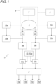
- FIG. 1 is a functional representation of an embodiment of a braking system of a vehicle according to the invention.
- the braking system makes it possible to actuate braking members 1a to 1b, 1c, 1d, in this case brake calipers, each associated with a brake disc of a wheel of the vehicle.
- the braking instructions are advantageously transmitted to the braking components 1a, 1b, 1c, 1d via a braking intensity distribution module 2 of the ABS and/or ESP type.
- the elements enabling this distribution of the hydraulic braking pressure to be carried out are intended to prevent the wheels from locking and/or to carry out a trajectory control/correction and are optional.
- the braking system advantageously comprises an additional hydraulic braking circuit 3, electrically controlled via a braking automation system 4.
- the braking automation system 4 comprises electrical and/or electronic components making it possible to implement functions for analyzing and comparing values of physical parameters measured by means of sensors arranged on the vehicle.
- the braking automaton 4 also makes it possible to receive, via a wired or wireless connection, information and/or braking instructions from a braking automaton 4 of another vehicle when the vehicles are coupled to form a convoy.
- the complementary hydraulic circuit 3 comprises a hydraulic supply subassembly 5.
- the latter comprises a hydraulic pump 6 connected to a reservoir 7 of hydraulic fluid, in this case a mineral oil.
- the braking controller 4 advantageously controls the operation of the hydraulic pump 6.
- the additional hydraulic circuit 3 also comprises two inverse proportional hydraulic valves 8a and 8b controlled by the braking automaton 4. Such an inverse proportional valve 8a, 8b is 100% open when it is not electrically powered.
- the inverse proportional hydraulic valves 8a and 8b make it possible to control a braking intensity on the braking members 1a and 1b, respectively 1c and 1d of two braking half-circuits of the vehicle.
- the inverse proportional hydraulic valves 8a and 8b make it possible to supply hydraulic fluid to fluid separators 9a and 9b respectively.
- the latter are advantageously constituted by a master cylinder making it possible on the one hand to transmit a braking intensity and on the other hand to use a different braking fluid to actuate the braking members 1a, 1b, 1c, 1d.
- the braking system according to the invention also comprises a manual hydraulic braking circuit 10.
- This manual hydraulic braking circuit 10 comprises, for example, a manual actuating member 10a connected to a master cylinder and connected to selectors 11a and 11b.
- the selectors 11a and 11b consist, for example, of electrically controlled hydraulic valves and make it possible to control a braking intensity for the braking members 1a, 1b, 1c and 1d either via the main hydraulic braking system 10 or via the supplementary hydraulic braking circuit 3.
- These selectors 11a and 11b make it possible to supply hydraulic fluid directly to the brake distribution module 2. It is thus possible to select either a manual braking mode using the manual hydraulic braking circuit 10, or an automatic braking mode, also called controlled braking.
- the additional hydraulic circuit 3 via the separators 9a and 9b, transmits hydraulic pressure to the module of distribution 2.
- the additional hydraulic circuit 3 comprises hydraulic energy accumulators 12a and 12b which are capable of acting on the fluid separators 9a and 9b.
- the hydraulic pump 6 When operating in controlled mode, the hydraulic pump 6 supplies the hydraulic energy accumulators 12a and 12b, which restore fluid pressure to the braking system according to instructions, but also in the event of failure, for example, of the hydraulic pump 6.
- the power supply subassembly 5 charges the hydraulic accumulators 12a and 12b via non-return valves 5a and 5b and hydraulic connection modules 15a and 15b.
- the hydraulic connection modules 15a and 15b advantageously integrate a system for controlling the energy reserve of the hydraulic accumulators 12a, 12b.
- a return circuit branch 3a makes it possible to provide fluid communication towards the reservoir 7 of the hydraulic power supply subassembly 5.
- the hydraulic accumulators 12a and 12b are connected to the respective inverse proportional valves 8a and 8b via respective sealing valves 16a and 16b. These sealing valves 16a and 16b make it possible to limit leaks in the hydraulic system linked to possible faults in the inverse proportional valves 8a, 8b and consequently to reduce the number of times the hydraulic pump 6 is started.
- the inverse proportional valves 8a and 8b are connected to the separator 9a and 9b via a circuit branch consisting of a parallel connection of an additional sealing valve 17a, 17b and a pressure limiter 13a, 13b.
- a circuit branch consisting of a parallel connection of an additional sealing valve 17a, 17b and a pressure limiter 13a, 13b.
- the additional sealing valves 17a, 17b are no longer electrically supplied and are in a non-passing position as illustrated in Figure 2
- the hydraulic fluid is then forced to pass through the pressure relief valves 13a, 13b.
- the complementary sealing valves 17a, 17b are not electrically powered and are in a passing position.
- the separators 9a and 9b are connected to the respective selectors 11a and 11b which allow a change from manual braking mode to a “controlled braking” mode or vice versa.
- the selectors 11a and 11b are valves arranged in a passing position corresponding to the controlled mode.
- the braking automaton 4 of the first vehicle when the additional braking circuit 3 equips two vehicles coupled to each other to form a convoy, the braking automaton 4 of the first vehicle, called the towing vehicle, transmits information to the braking automaton 4 of the second vehicle in trailer mode so as to switch the selectors 11a and 11b into a position corresponding to the activation of the controlled braking.
- the manual hydraulic braking circuit 10 of the vehicle in trailer mode is then deactivated.
- the hydraulic pump 6 charges the hydraulic accumulators 12a and 12b which provide the hydraulic pressures necessary for braking.
- the volume of these hydraulic accumulators 12a and 12b is high so as to benefit from a reserve of hydraulic energy in the event of failure of the hydraulic pump 6.
- the accumulators 12a and 12b are only used to implement braking in controlled mode and braking in safety mode.
- the inverse proportional valves 8a and 8b modulate the braking pressure in the complementary hydraulic circuit 3 according to a setpoint provided by the automaton 4 equipping the vehicle.
- the automaton 4 equipping the vehicle.
- wheel speed sensors, pressure sensors and accelerometers transmit the necessary information to the braking automaton 4 to allow braking control by said braking automaton 4.
- the sealing valves 16a and 16b and the inverse proportional valves 8a and 8b become open while the complementary sealing valves 17a and 17b are arranged in a non-open state.
- the hydraulic fluid can then no longer transmit a force to the separator 9a and 9b only via the respective pressure limiters 13a and 13b.
- the pressure limiters 13a and 13b are for example configured to limit the pressure to 30 bars, thus ensuring moderate emergency braking until the vehicle comes to a complete stop.
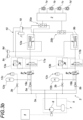
- FIG. 3a is a detailed hydraulic diagram of another example of the braking system of the Figure 1 .
- the inverse proportional valves 8a and 8b of the figures 1 And 2 are replaced respectively by proportional valves 18a and 18b.
- the manual hydraulic braking circuit 10 comprises for example a manual braking member associated with a master cylinder 19.
- the supplementary hydraulic circuit 3 and the manual braking circuit 10 are connected to the braking components 1a, 1b, 1c and 1d via a hydraulic “OR” valve.
- This hydraulic “OR” valve allows priority to be given to the supplementary hydraulic circuit 3 or the manual hydraulic circuit 10, providing the highest braking pressure.
- the proportional hydraulic valves 18a and 18b make it possible to actuate the respective separators 9a and 9b by means of a discharge of the hydraulic energy accumulators 12a and 12b.
- the pressure of the fluid contained in these hydraulic accumulators 12a and 12b is measured by pressure sensors 12c.
- the hydraulic accumulators 12a and 12b are charged by the hydraulic fluid thanks to the hydraulic pump 6, the activation and rotation speed of which are advantageously controlled by the braking automaton 4 as a function of the pressure measured by the sensors 12c.
- the braking automaton 4 controls the actuation of the hydraulic pump 6.
- Valves 3b are arranged in hydraulic circuit branches connecting accumulators 12a and 12b to return circuit branch 3a. These valves are used only for maintenance operations and are in a closed position during operation of the braking system.
- the separators 9a and 9b are advantageously connected to respective reservoirs 9c and 9d, containing the second hydraulic fluid, which acts directly on the braking members 1a, 1b, 1c, 1d.
- the supplementary braking circuit 3, illustrated in the Figure 3a thus allows the implementation of controlled braking, called controlled mode, for example for a conventional individual vehicle, an autonomous vehicle or a towed vehicle configured in trailer mode.
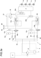
- FIG. 3b is a detailed hydraulic diagram of an additional example of the braking system of the Figure 1 .
- the additional hydraulic circuit 3 differs from that illustrated in the Figure 3a , in that it comprises between the proportional valves 18a, 18b and the separators 9a, 9b respectively a hydraulic circuit branch consisting of a parallel assembly of an additional sealing valve 17a, 17b and a pressure limiter 13a, 13b.
- the supplementary braking circuit 3, illustrated in the Figure 3b thus allows the implementation of controlled braking, called controlled mode, and emergency braking, called safety mode, for example for a conventional individual vehicle, an autonomous vehicle or a towed vehicle configured in trailer mode.
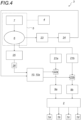
- FIG. 4 is a functional representation of another embodiment of the braking system according to the invention.
- the hydraulic pressure is stored in the hydraulic accumulators 21a and 21b intended for braking in manual mode by means of the manual braking hydraulic circuit 10 associated with an actuating pedal or an actuating member 10a.
- the separators 9a and 9b are consequently supplied by the respective hydraulic accumulators 21a and 21b and this by means of respective proportional valves 22a and 22b. The latter are actuated by the pedal or the actuating member 10a.
- a second hydraulic accumulator 23 charged by means of the hydraulic pump 6, delivers hydraulic pressure to the actuating member 10a via a proportional valve 24.
- the actuating member 10a is thus actuated, it is the latter which itself actuates the proportional valves 22a and 22b to transmit a force to the separators 9a and 9b.
- the actuating member 10a is advantageously equipped with a position sensor 10b, the position of which determines the desired braking power thanks to a corresponding activation amplitude of the proportional hydraulic valves 22a and 22b.
- the additional hydraulic circuit 3 further comprises a safety hydraulic accumulator 25 charged via the hydraulic pump 6 and releasing hydraulic pressure to actuate the actuating member 10a via a pressure limiter 26.
- the position of the member actuating valve 10a read by the position sensor 10b, again allows the proportional valves 22a and 22b to be controlled and thus emergency braking to be controlled by the pressure applied to the separator 9a and 9b.
- the proportional valves 22a and 22b are then in a passing state, the opening of which is not maximum but sufficient to guarantee degraded braking.
- the separators 9a and 9b are connected to respective reservoirs 9c and 9d containing a hydraulic fluid compatible with the braking members 1a, 1b, 1c and 1d, in this case calipers cooperating with braking discs.
- FIG. 5 is a detailed hydraulic diagram of an example of the braking system of the Figure 4 .
- the actuating member 10a is associated with the position sensor 10b.
- the position sensor 10b which provides position information for the actuating member 10a. This information is used to perform, using the braking automaton 4, a comparison between the braking power transmitted to the braking members 1a, 1b, 1c, 1d and the theoretical braking power given by the position of said actuating member 10a.
- Such a check makes it possible, for example, to detect an inconsistency between the braking pressure read by sensors at the pressure level of the braking members 1a, 1b, 1c, 1d and the position of the actuating pedal 10a.
- the check concerns braking in manual mode and braking in piloted mode. This makes it possible to check the integrity of said braking system.
- the proportional valves 22a and 22b of the slide valve type are mechanically connected to each other and directly actuated by the actuating pedal 10a.
- the hydraulic accumulators 21a and 21b and 25 are charged with hydraulic fluid to reach a predetermined pressure.
- This pressure can advantageously be read by means of any pressure measuring and reading device M. It is thus possible to check the hydraulic pressure prevailing inside these accumulators at any time.
- the proportional valves 22a and 22b distribute, via the accumulators 21a and 21b, the hydraulic power to the respective separators 9a and 9b.
- actuating member 10a In manual braking mode, it is the actuating member 10a which determines the position of the proportional valves 22a and 22b and this with a direct action of a user on said actuating pedal 10a.
- the proportional valve 24 In controlled braking mode, it is the proportional valve 24 which releases the hydraulic power of the hydraulic accumulator 23 on a port P1 of the actuating member 10a.
- the proportional valve 24 is, in this exemplary embodiment, controlled electrically and this by instructions from the braking automaton 4.
- the hydraulic accumulator 23 is advantageously connected to the proportional valve 24 by means of a sealing valve 24a thus avoiding any hydraulic leakage when braking in controlled mode is not active.
- a single valve 26a allows the hydraulic power of a hydraulic accumulator 25 to be released via a pressure limiter 26 to a second port P2 of the actuating pedal 10a. The latter then actuates the proportional valves 22a and 22b which in turn release hydraulic power from the hydraulic accumulators 21a and 21b to act on the hydraulic separators 9a and 9b.
- the single valve 26a advantageously allows braking to be generated before there is no more energy reserve in the hydraulic accumulators 21a and 21b or in the event of a fault, for example a leak, in the hydraulic circuit or in the event of an electrical/electronic fault.
- the hydraulic separators 9a and 9b are sized to compensate for the mechanical play occurring in the brake calipers and to compensate for the wear of the brake pads.
- the braking automaton 4 also makes it possible to automatically control the pressure prevailing inside the hydraulic accumulators 21a, 21b, 23 and 25 so as to detect any failure.
- the additional hydraulic circuit 3, illustrated in the Figure 5 thus allows the implementation of controlled braking, called controlled mode, and emergency braking, called safety mode, for example for a classic individual vehicle, an autonomous vehicle or a coupled vehicle configured in trailer mode.
- a braking intensity distribution module 2 As an example of an additional embodiment, it is possible to integrate in series between the separators 9a and 9b and the braking members 1a, 1b, 1c and 1d, a braking intensity distribution module 2, as shown diagrammatically in Figure 4 .
Landscapes
- Engineering & Computer Science (AREA)
- Transportation (AREA)
- Mechanical Engineering (AREA)
- Regulating Braking Force (AREA)
Claims (12)
- Bremssystem eines motorisierten Straßenfahrzeugs, das für Anhänger und für Zugmaschinen konfiguriert ist, um Bremsorgane (1a, 1b, 1c, 1d) des Fahrzeugs zu betätigen, die den Rädern des Fahrzeugs zugeordnet sind, wobei das System Steuerorgane zur Steuerung seines Betriebs und einen manuellen hydraulischen Bremskreis (10) umfasst, dadurch gekennzeichnet, dass es einen komplementären Hydraulikkreis (3) umfasst, mit dem das gleiche Fahrzeug ausgestattet ist, und der elektrisch gesteuert wird, wobei die Steuerorgane einen elektrischen Bremsroboter (4) umfassen, um Haupt- oder Zusatzbremsvorgaben zu erzeugen, die auf den komplementären Hydraulikkreis (3) übertragen werden.
- Bremssystem nach Anspruch 1, dadurch gekennzeichnet, dass es zur Ausstattung eines gezogenen Fahrzeugs gehört, dessen Konfiguration im Anhängermodus aktiviert ist, in dem der komplementäre Hydraulikkreis (3), der elektrisch über den Bremsroboter (4) gesteuert wird, aktiviert ist, wobei der Bremsroboter (4) ein Slave eines Master-Bremsroboter (4) eines anderen Fahrzeugs ist.
- Bremssystem nach Anspruch 1 oder 2, dadurch gekennzeichnet, dass das Bremssystem eine Sensorik zum Messen von Werten physikalischer Parameter für den Betrieb und die Nutzung des Fahrzeugs umfasst, wobei die Sensoren mit dem Bremsroboter (4) verbunden sind, um die gemessenen Werte an diesen zu übermitteln und automatisch Bremsvorgaben für den komplementären Hydraulikkreis (3) zu erzeugen und somit eine automatischen Bremsung einzuleiten.
- Bremssystem nach einem der Ansprüche 1 bis 3, dadurch gekennzeichnet, dass der ergänzende Hydraulikkreis (3) mindestens einen Speicher (21a, 21b, 23, 25, 12a, 12b) zum Speichern einer Hydraulikflüssigkeit unter einem hydraulischen Druck umfasst, der für die Durchführung von Bremsvorgängen geeignet ist.
- Bremssystem nach einem der Ansprüche 1 bis 4, dadurch gekennzeichnet, dass der Bremsroboter (4) Analyse- und/oder Vergleichsorgane umfasst, um einen Ausfall oder eine Störung des manuellen hydraulischen Bremskreises zu erkennen und Bremsvorgaben zu erzeugen, die einer Notbremsung des Fahrzeugs mit Hilfe des komplementären hydraulischen Bremskreises (3) entsprechen.
- Bremssystem nach einem der Ansprüche 1 bis 5, dadurch gekennzeichnet, dass der manuelle Hydraulikbremskreis ein manuelles Bremsorgan in der Art eines Bremsbetätigungspedals (10a) umfasst, das mit einem Positionssensor (10b) ausgestattet ist, der eine Information zur Verfügung stellt, die verwendet wird, um diese mit der Bremsleistung zu vergleichen, die auf die Bremsorgane (1a, 1b, 1c, 1d) übertragen wird, und dadurch die Integrität des Bremssystems zu überprüfen.
- Bremssystem nach den Ansprüchen 3 und 6, dadurch gekennzeichnet, dass es ein Organ umfasst, um einen autonomen Betriebsmodus auszuwählen, bei dem die automatische Bremsung aktiviert ist, oder einen manuellen Betriebsmodus, bei dem der hydraulische Kreis für die manuelle Bremsung (10) aktiviert ist.
- Bremssystem nach den Ansprüchen 3 und 6, dadurch gekennzeichnet, dass der manuelle hydraulische Bremskreis (10) und der komplementäre hydraulische Kreis (3) über ein hydraulisches "ODER"-Gatter mit den Bremsorganen (1a, 1b, 1c, 1d) verbunden sind, mit dem dem hydraulischen Kreis (3, 10) Vorrang eingeräumt werden kann, das den höchsten hydraulischen Bremsdruck aufweist.
- Bremssystem nach einem der Ansprüche 1 bis 8, dadurch gekennzeichnet, dass es ein Modul (2) zur Verteilung des hydraulischen Bremsdrucks in der Art eines ABS und/oder eines ESP umfasst.
- Fahrzeug mit einem Bremssystem nach einem der Ansprüche 1 bis 9, dadurch gekennzeichnet, dass es als Einzelfahrzeug konfiguriert ist.
- Autonomes Fahrzeug mit einem Bremssystem nach einem der Ansprüche 1 bis 9.
- Konvoi von Fahrzeugen, die durch eine mechanische oder immaterielle Kupplung miteinander verbunden sind, wobei der Konvoi ein Zugfahrzeug mit einem Bremssystem nach einem der Ansprüche 1 bis 9 und mindestens ein gezogenes Fahrzeug mit einem Bremssystem nach Anspruch 2 umfasst und der Bremsroboter (4) des Zugfahrzeugs über eine drahtgebundene oder drahtlose Kommunikationsverbindung, über welche die Bremsvorgaben für das gezogene Fahrzeug übertragen werden, mit dem Bremsroboter (4) des gezogenen Fahrzeugs verbunden ist.
Applications Claiming Priority (2)
| Application Number | Priority Date | Filing Date | Title |
|---|---|---|---|
| FR1853908A FR3080818B1 (fr) | 2018-05-04 | 2018-05-04 | Systeme de freinage ameliore et vehicule comportant un tel systeme de freinage |
| PCT/FR2019/051019 WO2019211569A1 (fr) | 2018-05-04 | 2019-05-03 | Systeme de freinage ameliore et vehicule comportant un tel systeme de freinage |
Publications (3)
| Publication Number | Publication Date |
|---|---|
| EP3787941A1 EP3787941A1 (de) | 2021-03-10 |
| EP3787941B1 true EP3787941B1 (de) | 2025-04-23 |
| EP3787941C0 EP3787941C0 (de) | 2025-04-23 |
Family
ID=62751156
Family Applications (1)
| Application Number | Title | Priority Date | Filing Date |
|---|---|---|---|
| EP19728490.4A Active EP3787941B1 (de) | 2018-05-04 | 2019-05-03 | Verbessertes bremssystem und fahrzeug mit einem solchen bremssystem |
Country Status (5)
| Country | Link |
|---|---|
| US (1) | US20210070270A1 (de) |
| EP (1) | EP3787941B1 (de) |
| FR (1) | FR3080818B1 (de) |
| PL (1) | PL3787941T3 (de) |
| WO (1) | WO2019211569A1 (de) |
Families Citing this family (2)
| Publication number | Priority date | Publication date | Assignee | Title |
|---|---|---|---|---|
| GB2580663B (en) * | 2019-01-22 | 2021-11-17 | Caterpillar Sarl | Brake control assembly with manual and electrical actuation |
| DE102020004483B3 (de) * | 2020-07-24 | 2021-09-02 | Daimler Ag | Verhindern einer Bewegung eines autonomen Fahrzeugs |
Citations (1)
| Publication number | Priority date | Publication date | Assignee | Title |
|---|---|---|---|---|
| US9315173B1 (en) * | 2012-11-30 | 2016-04-19 | Hopkins Manufacturing Corporation | Towed vehicle brake controls |
Family Cites Families (8)
| Publication number | Priority date | Publication date | Assignee | Title |
|---|---|---|---|---|
| FR2650237A1 (fr) * | 1989-07-27 | 1991-02-01 | Bendix France | Circuit hydraulique de freinage |
| FR2722464B1 (fr) * | 1994-07-18 | 1996-09-20 | Giat Ind Sa | Systeme de freinage unilateral pour vehicule motorise a roues |
| US5709435A (en) * | 1996-06-07 | 1998-01-20 | Ted Ruppel | Towed vehicle brake control system |
| FR2772706B1 (fr) * | 1997-12-22 | 2000-02-11 | Bosch Syst Freinage | Maitre-cylindre pour installation de freinage electro-hydraulique de vehicule automobile |
| RU2232685C1 (ru) * | 2002-11-25 | 2004-07-20 | Открытое акционерное общество "Красноярский алюминиевый завод" | Тягово-транспортное средство |
| DE102008026686A1 (de) * | 2008-06-04 | 2009-12-10 | Andreas Glindemann | Elektronische Deichsel |
| EP3437706B1 (de) * | 2015-02-26 | 2020-06-10 | Volvo Truck Corporation | Verfahren zur kontrolle des abstandes/der abstände zwischen den fahrzeugen in einer kolonne |
| FR3037023B1 (fr) * | 2015-06-03 | 2018-06-22 | Poclain Hydraulics Industrie | Systeme de freinage hydraulique d'un vehicule a plusieurs essieux, en particulier d'une remorque a plusieurs essieux |
-
2018
- 2018-05-04 FR FR1853908A patent/FR3080818B1/fr active Active
-
2019
- 2019-05-03 PL PL19728490.4T patent/PL3787941T3/pl unknown
- 2019-05-03 EP EP19728490.4A patent/EP3787941B1/de active Active
- 2019-05-03 US US17/040,839 patent/US20210070270A1/en not_active Abandoned
- 2019-05-03 WO PCT/FR2019/051019 patent/WO2019211569A1/fr not_active Ceased
Patent Citations (1)
| Publication number | Priority date | Publication date | Assignee | Title |
|---|---|---|---|---|
| US9315173B1 (en) * | 2012-11-30 | 2016-04-19 | Hopkins Manufacturing Corporation | Towed vehicle brake controls |
Also Published As
| Publication number | Publication date |
|---|---|
| WO2019211569A1 (fr) | 2019-11-07 |
| FR3080818B1 (fr) | 2021-10-01 |
| FR3080818A1 (fr) | 2019-11-08 |
| PL3787941T3 (pl) | 2025-06-16 |
| US20210070270A1 (en) | 2021-03-11 |
| EP3787941C0 (de) | 2025-04-23 |
| EP3787941A1 (de) | 2021-03-10 |
Similar Documents
| Publication | Publication Date | Title |
|---|---|---|
| EP3103691B1 (de) | Hydraulisches bremssystem eines mehrachsigen fahrzeugs, insbesondere eines mehrachsigen anhängers | |
| EP3423318B1 (de) | Eisenbahnbremssystem für schienenfahrzeug und verfahren zum bremsen eines schienenfahrzeugs mit solch einem system | |
| EP3787941B1 (de) | Verbessertes bremssystem und fahrzeug mit einem solchen bremssystem | |
| FR3048399A1 (fr) | Systeme de freinage ferroviaire pour vehicule ferroviaire et procede de freinage d'un vehicule ferroviaire comportant un tel systeme | |
| EP0334723B1 (de) | Steuervorrichtung für einen hydraulischen doppelt wirkenden Arbeitszylinder | |
| FR2597052A1 (fr) | Systeme hydraulique de freinage equipe d'un dispositif de regulation du glissement de roue | |
| EP3814182B1 (de) | Verbessertes verfahren und system zur hydraulischen bremsung für ein fahrzeug mit kupplung | |
| EP3532331A1 (de) | System zur unterstützung des fahrens eines anhängers von einem offenen kipphydraulikkreis | |
| WO2020012096A1 (fr) | Procede et circuit de freinage hydraulique d'urgence ameliores pour attelage | |
| EP1800983B1 (de) | Hydraulische Bremssteuerung eines Anhängers | |
| EP3222478B1 (de) | Redundante bremsvorrichtung | |
| EP3279046A1 (de) | Bremskreis, fahrzeug mit einem derartigen bremskreis und bremssteuerverfahren eines fahrzeugs. | |
| EP1827940B1 (de) | Bremsvorrichtung für ein industriefahrzeug | |
| EP3934953B1 (de) | Schienenbremssystem mit einer parkbremsanzeigevorrichtung und schienenfahrzeug mit einem solchen system | |
| EP1503925A1 (de) | Bremsvorrichtung für die achse eines industriefahrzeugs | |
| EP2620337A2 (de) | Bremsvorrichtung, insbesondere für ein gewerbliches Fahrzeug | |
| FR3105138A3 (fr) | Procédé de pilotage du freinage d'un véhicule, par exemple un véhicule agricole. | |
| EP1968836B1 (de) | Bremsvorrichtung für ein nutzfahrzeug | |
| CA3130037A1 (fr) | Systeme de freinage ferroviaire comportant un dispositif afficheur d'un etat d'un frein de service et/ou d'un etat d'un frein de parking et vehicule ferroviaire pourvu d'un tel systeme | |
| FR2928324A1 (fr) | Systeme de freinage avec controle de stabilite et de trajectoire. | |
| FR3102126A1 (fr) | Système et procédé amélioré de commande pour une valve de freinage | |
| FR2928118A1 (fr) | Systeme de regulation du freinage pour le controle de stabilite et de trajectoire d'un vehicule automobile |
Legal Events
| Date | Code | Title | Description |
|---|---|---|---|
| STAA | Information on the status of an ep patent application or granted ep patent |
Free format text: STATUS: UNKNOWN |
|
| STAA | Information on the status of an ep patent application or granted ep patent |
Free format text: STATUS: THE INTERNATIONAL PUBLICATION HAS BEEN MADE |
|
| PUAI | Public reference made under article 153(3) epc to a published international application that has entered the european phase |
Free format text: ORIGINAL CODE: 0009012 |
|
| STAA | Information on the status of an ep patent application or granted ep patent |
Free format text: STATUS: REQUEST FOR EXAMINATION WAS MADE |
|
| 17P | Request for examination filed |
Effective date: 20200922 |
|
| AK | Designated contracting states |
Kind code of ref document: A1 Designated state(s): AL AT BE BG CH CY CZ DE DK EE ES FI FR GB GR HR HU IE IS IT LI LT LU LV MC MK MT NL NO PL PT RO RS SE SI SK SM TR |
|
| AX | Request for extension of the european patent |
Extension state: BA ME |
|
| RAP1 | Party data changed (applicant data changed or rights of an application transferred) |
Owner name: LOHR INDUSTRIE |
|
| DAV | Request for validation of the european patent (deleted) | ||
| DAX | Request for extension of the european patent (deleted) | ||
| STAA | Information on the status of an ep patent application or granted ep patent |
Free format text: STATUS: EXAMINATION IS IN PROGRESS |
|
| 17Q | First examination report despatched |
Effective date: 20230306 |
|
| GRAP | Despatch of communication of intention to grant a patent |
Free format text: ORIGINAL CODE: EPIDOSNIGR1 |
|
| STAA | Information on the status of an ep patent application or granted ep patent |
Free format text: STATUS: GRANT OF PATENT IS INTENDED |
|
| INTG | Intention to grant announced |
Effective date: 20241209 |
|
| GRAS | Grant fee paid |
Free format text: ORIGINAL CODE: EPIDOSNIGR3 |
|
| GRAA | (expected) grant |
Free format text: ORIGINAL CODE: 0009210 |
|
| STAA | Information on the status of an ep patent application or granted ep patent |
Free format text: STATUS: THE PATENT HAS BEEN GRANTED |
|
| AK | Designated contracting states |
Kind code of ref document: B1 Designated state(s): AL AT BE BG CH CY CZ DE DK EE ES FI FR GB GR HR HU IE IS IT LI LT LU LV MC MK MT NL NO PL PT RO RS SE SI SK SM TR |
|
| REG | Reference to a national code |
Ref country code: GB Ref legal event code: FG4D Free format text: NOT ENGLISH |
|
| REG | Reference to a national code |
Ref country code: CH Ref legal event code: EP |
|
| REG | Reference to a national code |
Ref country code: IE Ref legal event code: FG4D Free format text: LANGUAGE OF EP DOCUMENT: FRENCH |
|
| U01 | Request for unitary effect filed |
Effective date: 20250423 |
|
| U07 | Unitary effect registered |
Designated state(s): AT BE BG DE DK EE FI FR IT LT LU LV MT NL PT RO SE SI Effective date: 20250428 |
|
| U20 | Renewal fee for the european patent with unitary effect paid |
Year of fee payment: 7 Effective date: 20250520 |
|
| PGFP | Annual fee paid to national office [announced via postgrant information from national office to epo] |
Ref country code: PL Payment date: 20250425 Year of fee payment: 7 |
|
| PGFP | Annual fee paid to national office [announced via postgrant information from national office to epo] |
Ref country code: CH Payment date: 20250601 Year of fee payment: 7 |
|
| PG25 | Lapsed in a contracting state [announced via postgrant information from national office to epo] |
Ref country code: ES Free format text: LAPSE BECAUSE OF FAILURE TO SUBMIT A TRANSLATION OF THE DESCRIPTION OR TO PAY THE FEE WITHIN THE PRESCRIBED TIME-LIMIT Effective date: 20250423 |
|
| PG25 | Lapsed in a contracting state [announced via postgrant information from national office to epo] |
Ref country code: GR Free format text: LAPSE BECAUSE OF FAILURE TO SUBMIT A TRANSLATION OF THE DESCRIPTION OR TO PAY THE FEE WITHIN THE PRESCRIBED TIME-LIMIT Effective date: 20250724 Ref country code: NO Free format text: LAPSE BECAUSE OF FAILURE TO SUBMIT A TRANSLATION OF THE DESCRIPTION OR TO PAY THE FEE WITHIN THE PRESCRIBED TIME-LIMIT Effective date: 20250723 |
|
| PG25 | Lapsed in a contracting state [announced via postgrant information from national office to epo] |
Ref country code: HR Free format text: LAPSE BECAUSE OF FAILURE TO SUBMIT A TRANSLATION OF THE DESCRIPTION OR TO PAY THE FEE WITHIN THE PRESCRIBED TIME-LIMIT Effective date: 20250423 |
|
| PG25 | Lapsed in a contracting state [announced via postgrant information from national office to epo] |
Ref country code: RS Free format text: LAPSE BECAUSE OF FAILURE TO SUBMIT A TRANSLATION OF THE DESCRIPTION OR TO PAY THE FEE WITHIN THE PRESCRIBED TIME-LIMIT Effective date: 20250723 |
|
| PG25 | Lapsed in a contracting state [announced via postgrant information from national office to epo] |
Ref country code: IS Free format text: LAPSE BECAUSE OF FAILURE TO SUBMIT A TRANSLATION OF THE DESCRIPTION OR TO PAY THE FEE WITHIN THE PRESCRIBED TIME-LIMIT Effective date: 20250823 |