EP3787801B1 - Buse microstructurée - Google Patents
Buse microstructurée Download PDFInfo
- Publication number
- EP3787801B1 EP3787801B1 EP18917218.2A EP18917218A EP3787801B1 EP 3787801 B1 EP3787801 B1 EP 3787801B1 EP 18917218 A EP18917218 A EP 18917218A EP 3787801 B1 EP3787801 B1 EP 3787801B1
- Authority
- EP
- European Patent Office
- Prior art keywords
- liquid
- aerosol
- passage module
- less
- width
- Prior art date
- Legal status (The legal status is an assumption and is not a legal conclusion. Google has not performed a legal analysis and makes no representation as to the accuracy of the status listed.)
- Active
Links
- 239000007788 liquid Substances 0.000 claims description 95
- 239000000443 aerosol Substances 0.000 claims description 64
- 239000003814 drug Substances 0.000 claims description 61
- 239000007921 spray Substances 0.000 claims description 24
- 238000001914 filtration Methods 0.000 claims description 15
- 238000003860 storage Methods 0.000 claims description 10
- 210000004072 lung Anatomy 0.000 claims description 9
- 239000008186 active pharmaceutical agent Substances 0.000 claims description 8
- KCXVZYZYPLLWCC-UHFFFAOYSA-N EDTA Chemical group OC(=O)CN(CC(O)=O)CCN(CC(O)=O)CC(O)=O KCXVZYZYPLLWCC-UHFFFAOYSA-N 0.000 claims description 6
- 239000003381 stabilizer Substances 0.000 claims description 6
- 239000003755 preservative agent Substances 0.000 claims description 4
- 239000000808 adrenergic beta-agonist Substances 0.000 claims description 3
- 230000003266 anti-allergic effect Effects 0.000 claims description 3
- 239000000043 antiallergic agent Substances 0.000 claims description 3
- 229940065524 anticholinergics inhalants for obstructive airway diseases Drugs 0.000 claims description 3
- 239000000739 antihistaminic agent Substances 0.000 claims description 3
- 229940125715 antihistaminic agent Drugs 0.000 claims description 3
- 230000003454 betamimetic effect Effects 0.000 claims description 3
- 239000000812 cholinergic antagonist Substances 0.000 claims description 3
- 125000003158 alcohol group Chemical group 0.000 claims 1
- 229940079593 drug Drugs 0.000 description 12
- 239000002245 particle Substances 0.000 description 10
- 238000012387 aerosolization Methods 0.000 description 9
- 125000006850 spacer group Chemical group 0.000 description 9
- 239000000243 solution Substances 0.000 description 8
- 238000009472 formulation Methods 0.000 description 7
- 238000004519 manufacturing process Methods 0.000 description 7
- 239000000203 mixture Substances 0.000 description 7
- 239000003380 propellant Substances 0.000 description 7
- 239000010419 fine particle Substances 0.000 description 5
- 239000007864 aqueous solution Substances 0.000 description 4
- 230000015572 biosynthetic process Effects 0.000 description 4
- KRKNYBCHXYNGOX-UHFFFAOYSA-N citric acid Chemical compound OC(=O)CC(O)(C(O)=O)CC(O)=O KRKNYBCHXYNGOX-UHFFFAOYSA-N 0.000 description 3
- 230000000694 effects Effects 0.000 description 3
- LFQSCWFLJHTTHZ-UHFFFAOYSA-N Ethanol Chemical compound CCO LFQSCWFLJHTTHZ-UHFFFAOYSA-N 0.000 description 2
- VEXZGXHMUGYJMC-UHFFFAOYSA-N Hydrochloric acid Chemical compound Cl VEXZGXHMUGYJMC-UHFFFAOYSA-N 0.000 description 2
- 230000008901 benefit Effects 0.000 description 2
- 230000008021 deposition Effects 0.000 description 2
- 239000012530 fluid Substances 0.000 description 2
- 239000004615 ingredient Substances 0.000 description 2
- 238000002664 inhalation therapy Methods 0.000 description 2
- 230000000670 limiting effect Effects 0.000 description 2
- 238000005259 measurement Methods 0.000 description 2
- 230000007246 mechanism Effects 0.000 description 2
- 238000000034 method Methods 0.000 description 2
- 230000008569 process Effects 0.000 description 2
- 230000002829 reductive effect Effects 0.000 description 2
- 230000004044 response Effects 0.000 description 2
- 150000003431 steroids Chemical class 0.000 description 2
- LSLYOANBFKQKPT-DIFFPNOSSA-N 5-[(1r)-1-hydroxy-2-[[(2r)-1-(4-hydroxyphenyl)propan-2-yl]amino]ethyl]benzene-1,3-diol Chemical compound C([C@@H](C)NC[C@H](O)C=1C=C(O)C=C(O)C=1)C1=CC=C(O)C=C1 LSLYOANBFKQKPT-DIFFPNOSSA-N 0.000 description 1
- VOVIALXJUBGFJZ-KWVAZRHASA-N Budesonide Chemical compound C1CC2=CC(=O)C=C[C@]2(C)[C@@H]2[C@@H]1[C@@H]1C[C@H]3OC(CCC)O[C@@]3(C(=O)CO)[C@@]1(C)C[C@@H]2O VOVIALXJUBGFJZ-KWVAZRHASA-N 0.000 description 1
- LERNTVKEWCAPOY-VOGVJGKGSA-N C[N+]1(C)[C@H]2C[C@H](C[C@@H]1[C@H]1O[C@@H]21)OC(=O)C(O)(c1cccs1)c1cccs1 Chemical compound C[N+]1(C)[C@H]2C[C@H](C[C@@H]1[C@H]1O[C@@H]21)OC(=O)C(O)(c1cccs1)c1cccs1 LERNTVKEWCAPOY-VOGVJGKGSA-N 0.000 description 1
- 208000006545 Chronic Obstructive Pulmonary Disease Diseases 0.000 description 1
- 208000033999 Device damage Diseases 0.000 description 1
- 238000010521 absorption reaction Methods 0.000 description 1
- 230000002378 acidificating effect Effects 0.000 description 1
- 239000004480 active ingredient Substances 0.000 description 1
- 230000002411 adverse Effects 0.000 description 1
- 229940057282 albuterol sulfate Drugs 0.000 description 1
- BNPSSFBOAGDEEL-UHFFFAOYSA-N albuterol sulfate Chemical compound OS(O)(=O)=O.CC(C)(C)NCC(O)C1=CC=C(O)C(CO)=C1.CC(C)(C)NCC(O)C1=CC=C(O)C(CO)=C1 BNPSSFBOAGDEEL-UHFFFAOYSA-N 0.000 description 1
- 208000006673 asthma Diseases 0.000 description 1
- 230000009286 beneficial effect Effects 0.000 description 1
- 229960001716 benzalkonium Drugs 0.000 description 1
- 229960000686 benzalkonium chloride Drugs 0.000 description 1
- CYDRXTMLKJDRQH-UHFFFAOYSA-N benzododecinium Chemical compound CCCCCCCCCCCC[N+](C)(C)CC1=CC=CC=C1 CYDRXTMLKJDRQH-UHFFFAOYSA-N 0.000 description 1
- CADWTSSKOVRVJC-UHFFFAOYSA-N benzyl(dimethyl)azanium;chloride Chemical compound [Cl-].C[NH+](C)CC1=CC=CC=C1 CADWTSSKOVRVJC-UHFFFAOYSA-N 0.000 description 1
- 229960004436 budesonide Drugs 0.000 description 1
- 230000008859 change Effects 0.000 description 1
- KYKAJFCTULSVSH-UHFFFAOYSA-N chloro(fluoro)methane Chemical compound F[C]Cl KYKAJFCTULSVSH-UHFFFAOYSA-N 0.000 description 1
- 230000001010 compromised effect Effects 0.000 description 1
- 230000007797 corrosion Effects 0.000 description 1
- 238000005260 corrosion Methods 0.000 description 1
- 238000002425 crystallisation Methods 0.000 description 1
- 230000008025 crystallization Effects 0.000 description 1
- 230000001419 dependent effect Effects 0.000 description 1
- 238000009826 distribution Methods 0.000 description 1
- 230000007613 environmental effect Effects 0.000 description 1
- 238000005530 etching Methods 0.000 description 1
- 229960001022 fenoterol Drugs 0.000 description 1
- 229960002848 formoterol Drugs 0.000 description 1
- BPZSYCZIITTYBL-UHFFFAOYSA-N formoterol Chemical compound C1=CC(OC)=CC=C1CC(C)NCC(O)C1=CC=C(O)C(NC=O)=C1 BPZSYCZIITTYBL-UHFFFAOYSA-N 0.000 description 1
- 239000007789 gas Substances 0.000 description 1
- 239000011521 glass Substances 0.000 description 1
- 150000005828 hydrofluoroalkanes Chemical class 0.000 description 1
- 230000003993 interaction Effects 0.000 description 1
- 229960001361 ipratropium bromide Drugs 0.000 description 1
- KEWHKYJURDBRMN-ZEODDXGYSA-M ipratropium bromide hydrate Chemical compound O.[Br-].O([C@H]1C[C@H]2CC[C@@H](C1)[N@@+]2(C)C(C)C)C(=O)C(CO)C1=CC=CC=C1 KEWHKYJURDBRMN-ZEODDXGYSA-M 0.000 description 1
- 239000006193 liquid solution Substances 0.000 description 1
- 239000003595 mist Substances 0.000 description 1
- 238000000465 moulding Methods 0.000 description 1
- 239000007922 nasal spray Substances 0.000 description 1
- 239000006199 nebulizer Substances 0.000 description 1
- 229960004286 olodaterol Drugs 0.000 description 1
- COUYJEVMBVSIHV-SFHVURJKSA-N olodaterol Chemical compound C1=CC(OC)=CC=C1CC(C)(C)NC[C@H](O)C1=CC(O)=CC2=C1OCC(=O)N2 COUYJEVMBVSIHV-SFHVURJKSA-N 0.000 description 1
- 239000000843 powder Substances 0.000 description 1
- 238000002360 preparation method Methods 0.000 description 1
- 230000002335 preservative effect Effects 0.000 description 1
- 238000007639 printing Methods 0.000 description 1
- 230000009467 reduction Effects 0.000 description 1
- 230000000241 respiratory effect Effects 0.000 description 1
- 229910052710 silicon Inorganic materials 0.000 description 1
- 239000010703 silicon Substances 0.000 description 1
- 238000005507 spraying Methods 0.000 description 1
- 230000002123 temporal effect Effects 0.000 description 1
- 238000002560 therapeutic procedure Methods 0.000 description 1
- 229940110309 tiotropium Drugs 0.000 description 1
- LERNTVKEWCAPOY-DZZGSBJMSA-N tiotropium Chemical compound O([C@H]1C[C@@H]2[N+]([C@H](C1)[C@@H]1[C@H]2O1)(C)C)C(=O)C(O)(C=1SC=CC=1)C1=CC=CS1 LERNTVKEWCAPOY-DZZGSBJMSA-N 0.000 description 1
- 229960000257 tiotropium bromide Drugs 0.000 description 1
- 230000001960 triggered effect Effects 0.000 description 1
- 239000002699 waste material Substances 0.000 description 1
- 238000003466 welding Methods 0.000 description 1
Images


Classifications
-
- B—PERFORMING OPERATIONS; TRANSPORTING
- B05—SPRAYING OR ATOMISING IN GENERAL; APPLYING FLUENT MATERIALS TO SURFACES, IN GENERAL
- B05B—SPRAYING APPARATUS; ATOMISING APPARATUS; NOZZLES
- B05B15/00—Details of spraying plant or spraying apparatus not otherwise provided for; Accessories
- B05B15/40—Filters located upstream of the spraying outlets
-
- A—HUMAN NECESSITIES
- A61—MEDICAL OR VETERINARY SCIENCE; HYGIENE
- A61M—DEVICES FOR INTRODUCING MEDIA INTO, OR ONTO, THE BODY; DEVICES FOR TRANSDUCING BODY MEDIA OR FOR TAKING MEDIA FROM THE BODY; DEVICES FOR PRODUCING OR ENDING SLEEP OR STUPOR
- A61M11/00—Sprayers or atomisers specially adapted for therapeutic purposes
- A61M11/001—Particle size control
- A61M11/003—Particle size control by passing the aerosol trough sieves or filters
-
- A—HUMAN NECESSITIES
- A61—MEDICAL OR VETERINARY SCIENCE; HYGIENE
- A61M—DEVICES FOR INTRODUCING MEDIA INTO, OR ONTO, THE BODY; DEVICES FOR TRANSDUCING BODY MEDIA OR FOR TAKING MEDIA FROM THE BODY; DEVICES FOR PRODUCING OR ENDING SLEEP OR STUPOR
- A61M11/00—Sprayers or atomisers specially adapted for therapeutic purposes
- A61M11/006—Sprayers or atomisers specially adapted for therapeutic purposes operated by applying mechanical pressure to the liquid to be sprayed or atomised
- A61M11/007—Syringe-type or piston-type sprayers or atomisers
-
- A—HUMAN NECESSITIES
- A61—MEDICAL OR VETERINARY SCIENCE; HYGIENE
- A61M—DEVICES FOR INTRODUCING MEDIA INTO, OR ONTO, THE BODY; DEVICES FOR TRANSDUCING BODY MEDIA OR FOR TAKING MEDIA FROM THE BODY; DEVICES FOR PRODUCING OR ENDING SLEEP OR STUPOR
- A61M15/00—Inhalators
- A61M15/0065—Inhalators with dosage or measuring devices
-
- A—HUMAN NECESSITIES
- A61—MEDICAL OR VETERINARY SCIENCE; HYGIENE
- A61M—DEVICES FOR INTRODUCING MEDIA INTO, OR ONTO, THE BODY; DEVICES FOR TRANSDUCING BODY MEDIA OR FOR TAKING MEDIA FROM THE BODY; DEVICES FOR PRODUCING OR ENDING SLEEP OR STUPOR
- A61M2207/00—Methods of manufacture, assembly or production
-
- B—PERFORMING OPERATIONS; TRANSPORTING
- B05—SPRAYING OR ATOMISING IN GENERAL; APPLYING FLUENT MATERIALS TO SURFACES, IN GENERAL
- B05B—SPRAYING APPARATUS; ATOMISING APPARATUS; NOZZLES
- B05B11/00—Single-unit hand-held apparatus in which flow of contents is produced by the muscular force of the operator at the moment of use
- B05B11/01—Single-unit hand-held apparatus in which flow of contents is produced by the muscular force of the operator at the moment of use characterised by the means producing the flow
- B05B11/10—Pump arrangements for transferring the contents from the container to a pump chamber by a sucking effect and forcing the contents out through the dispensing nozzle
- B05B11/109—Pump arrangements for transferring the contents from the container to a pump chamber by a sucking effect and forcing the contents out through the dispensing nozzle the dispensing stroke being affected by the stored energy of a spring
- B05B11/1091—Pump arrangements for transferring the contents from the container to a pump chamber by a sucking effect and forcing the contents out through the dispensing nozzle the dispensing stroke being affected by the stored energy of a spring being first hold in a loaded state by locking means or the like, then released
Definitions
- the present disclosure relates to a microstructured passage module and more particularly to a microstructured passage module for an aerosol generator.
- Aerosolizer also known as nebulizer or atomizer
- nebulizer or atomizer is used to deliver medication to patients for inhalation.
- liquid medicament is broken down into aerosol having fine particles/droplets for easier and more efficient inhalation and absorption.
- the particle size may be adjusted depending on different respiratory conditions, such as Chronic Obstructive Pulmonary Disease (COPD) or asthma, or depending on the requirement of the liquid medicament itself.
- COPD Chronic Obstructive Pulmonary Disease
- COPD Chronic Obstructive Pulmonary Disease
- the ability to receive the same precise amount of medication in each treatment is also very important for patients.
- a good aerosolizer should be able to deliver a precise dosage of medication having a fixed average particle size, a certain range of MMAD (Mass Median Aerodynamic Diameter), and at certain spray duration in every operation to reduce waste and risks of overdosing.
- MMAD Mass Median Aerodynamic Diameter
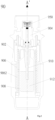
- an exemplary aerosolizer includes an upper housing 964, a lower housing 965, a nozzle 963, a tube 966, a biasing element 962 and a storage container 961.
- the biasing element 962 such as a spring
- a fixed amount liquid medicament is drawn from the storage container 961 by the tube 966 and to the nozzle 963, ready to be aerosolized.
- a force generated by the un-tensioned biasing element 962 pushes the fixed amount of liquid medicament towards and through the nozzle 963, thereby creating the aerosol for inhalation.
- Another exemplary aerosolizer and the operation mechanism thereof can be referenced to the disclosure in US5964416 ( US Patent Application Number: 08/726,219 ).
- pressurized liquid medicament travels in the direction from A to A', i.e., from a high pressure point to a low pressure point.
- Liquid medicament is drawn and forced into the nozzle 963, through which aerosol is generated and exited out.
- the nozzle 963 plays a pivotal role in whether the pressurized liquid medicament can be aerosolized into fine particles/droplets and exit the aerosolizer at a certain speed.
- the pressurized liquid medicament travels through the central connecting tube to the nozzle 963.
- the pressurized liquid medicament generally flows into the nozzle 963 at a high speed.
- the nozzle 963 serves to filter and decrease the flow speed of the liquid medicament in a controlled manner such that precise dosage of medicament can be aerosolized into the desired aerosol form.
- the foregoing may be achieved through specifically configured internal structure of the nozzle 963. Improper design of the nozzle 963 may lead to blockage to the entire aerosolization process, which may shorten the life of the aerosolizer or affect dosage accuracy.
- a typical nozzle used in an aerosolizer includes multiple elements with different geometric shapes. For example, some elements with a particular shape, e.g., elongated projections, are used as filters. Some other elements with a different shape, e.g., cylindrical projections, are used to structure a guiding system to control the liquid flow in the nozzle.
- a nozzle used in the relevant art requires the combination and interaction of multiple elements having different structural and/or functional characteristics in order to achieve the desired aerosolization effect.
- fluid control therein is not easy.
- the structure, dimension and arrangement of the elements in the nozzle need to be carefully implemented to make the nozzle effective. As a result, the costs for the design and manufacture of the nozzle tends to be high.
- Document EP1493492A1 relates to a micro structured high pressure nozzle unit with built in filter function for high pressure atomizers for nebulizing fluids.
- the present disclosure aims to provide a nozzle structure with less complicated structure, design and arrangement.
- the resulting nozzle will improve the overall aerosolization quality and efficiency, while the cost for manufacturing such nozzle is reduced. Accordingly, patients can enjoy a more affordable treatment solution.
- a microstructured passage module for an aerosol generator.
- the module includes a plate overlaid by a cover thus forming a compartment, an entrance for a liquid and an exit.
- the plate further includes a filtering structure.
- An exemplary filtering structure includes walls, pillars, protrusions, and combination thereof.
- the plate includes a plurality of walls parallel to each other over its entire width so as to define a plurality of passages threrebetween. The walls are arranged along a flow direction, which is substantially perpendicular to the entrance.
- a plurality of pillars protruding from the plate are evenly distributed in at least a section of the passages.
- the wall could be configured continuously or un-continuously.
- a column is disposed proximate to the exit and blocks a substantial part thereof, leaving longitudinal aisles for the liquid to leave via the exit. The liquid flows through the compartment from the entrance to the exit such that an aerosol is produced.
- a distance between two adjacent pillars is D and the longitudinal aisle has a width W.
- the D and the W are specifically configured such that the aerosol has a predetermined MMAD.
- the distance D and the width W are specifically configured to effectively deliver aerosolized drug to patient's lung.
- the aerosol must have an MMAD value less than 5.5 um and preferably between 4 um to 5.5 um. Further, for aerosol having MMAD less than 5.5 um, the spray duration is preferred to be approximately 1.6 seconds. Said combination increases the effectiveness of fine particles to be delivered into specific lung regions of a user, thus resulting in a more desirable treatment result.
- the microstructured passage module and the components thereof are specifically configured and arranged such that liquid medicament having certain characteristics can be aerosolized to have predetermined and consistent MMAD and spray duration, under certain liquid medicament conditions.
- the formulation of liquid medicament contains active pharmaceutical ingredients, stabilizer and preservatives.
- the active pharmaceutical ingredient may be selected singly or in combination from the group of betamimetics, anticholinergics, antiallergics, antihistamines, and/or steroids.
- the liquid medicament is ethanol-free and may possess certain range of characteristics, such as viscosity and surface tension.
- FIG. 2 is a cross-sectional view of an exemplary aerosolizer according to the present disclosure.
- the aerosolizer 90 includes a housing 902 with a pump chamber 904 and a spring chamber 906.
- a biasing element 9062 such as a spring, is coupled to the housing 902, and more particularly is mounted in the spring chamber 906.
- the spring chamber 906 also holds a storage container 908 where liquid medicament 912 is stored.
- Such liquid medicament 912 can be drawn from the storage container 908 via a tube 910 in response to a pre-actuation of the aerosolizer 90.
- the housing 902 is rotated.
- the spring 9062 is adapted to respond to such rotation by tensioning.
- the liquid medicament 912 is drawn from the storage container 908 into the pump chamber 904, ready to be aerosolized.
- the aerosolization process starts when the aerosolizer 90 is actuated.
- a release mechanism (not shown) is triggered and the spring 9062 is released from the tensioned state to the untensioned state.
- Such operation results in a force pushing the liquid medicament 912 through a transfusion apparatus 950, where a microstructured passage module 1 (e.g., a nozzle) resides (see FIG. 3A ), at the pump chamber 904.
- a microstructured passage module 1 e.g., a nozzle
- the microstructured passage module 1 is specifically configured such that aerosol having desired particle size in a controlled and precise delivery manner can be produced. Consequently, aerosolized liquid medicament exits the transfusion apparatus 950 and then out of the aerosolizer 90 for patient inhalation.
- An exemplary liquid medicament contains respirable formulation.
- the liquid medicament may be an aqueous solution.
- the liquid medicament is ethanol-free. In other words, the liquid medicament contains no ethanol. More details of the liquid medicament will be discussed later.
- the liquid medicament contains no propellant (exemplary propellants include chlorofluorocarbon or hydrofluoroalkane propellants).
- Propellants are the driving source for atomized aerosol containing drugs for what's commonly known as pressurized metered dose inhalers (MDI).
- MDI pressurized metered dose inhalers
- propellants may have adverse impact to the environment.
- an aerosolizer is operable without propellants, as disclosed in the present disclosure.
- the microstructured passage module 1 is the pivotal component of the aerosolizer 90 where liquid medicament can be broken down into aerosol having fine particles/droplet.
- the microstructured passage module 1 of the aerosolizer 90 is a component having a microstructured filtering and guiding system, which consists of a plurality of microscale elements and a plurality of passages defined by such microscale elements.
- a microstructured filtering and guiding system which consists of a plurality of microscale elements and a plurality of passages defined by such microscale elements.
- an ideal aerosol should have certain ranges of MMAD and spray duration.
- the MMAD should be less than 5.5 um, and the spray duration is between about 1.2 and about 1.6 seconds.
- the MMAD is between about 4 um and 6 um; and the spray duration is between about 1.2 and about 1.6 seconds, and more preferably between about 1.4 and about 1.6 seconds.
- An aerosol having MMAD between about 4 um and 6 um is desirable for inhalation therapy.
- An aerosol having MMAD higher than such range makes it harder to reach the patient's lung. For example, the aerosol is more likely to be deposited at the throat.
- an MMAD lower than such range increases the chance of undesired aerosol dissemination.
- not enough aerosol reaches the patient's lung, and the therapy is considered ineffective.
- spray duration if that of the aerosol falls out the foregoing range, the inhalation efficiency of the patient will be affected. The chance of clogging or residue may increase, thereby affecting treatment.
- undesired spray duration may negatively affect the amount of aerosolized medicament a patient inhales at a given time.
- the present disclosure provides a passage module 1 to better achieve the foregoing MMAD and spray duration. More details of the resulting aerosol will be discussed later.
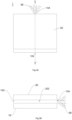
- FIGs. 3A-3B show an exemplary passage module 1 1 in accordance with some embodiments of the present disclosure.
- FIG. 3A is a top view of the passage module 1 1 in accordance with some embodiments of the present disclosure.
- the passage module 1 1 includes a cover 20 and a plate (blocked by the cover 20, not shown). Together, the foregoing forms a compartment to accommodate a filtering structure. Liquid (not shown) enters the compartment via the entrance 102 and leaves in aerosol form via the exit 104.
- the filtering structure thereof ensures that the resulting aerosol 50 possesses certain characteristics suitable for human inhalation therapy. For example, the aerosol 50 possesses certain MMAD and spray duration as disclosed herein.
- FIB. 3B is a sectional view of the passage module 1 1 along the dotted line X-X' as shown in FIG. 3A .
- the plate 10 and the cover 20 in combination define the entrance 102 for the liquid (not shown) and the exit 104.
- the plate 10 and the cover 20 form a compartment 202.
- the compartment 202 encompasses the filtering structure (omitted for clarity), which is designed to guide the liquid direction or change a flow speed thereof.
- the filtering structure may be in contact with both the plate 10 and the cover 20, or not.
- An example of the filtering structure may be protrusions, pillars, walls or the combination thereof protruding from the plate 10. With the configuration of the filtering structure, the resulting aerosol 50 possesses the desired MMAD and spray duration disclosed herein.
- FIGs. 4A-4C are cross-section views of the passage module 1 1 in accordance with some embodiments of the present disclosure.
- the microstructured passage module 1 includes a plate 10, which can be made from silicon and is about 2.5 mm in width, about 2 mm in length and about 700 um in depth.
- the plate 10 is overlaid by a glass cover (not shown), which is about 2.5 mm in width, about 2 mm in length and about 675 um in depth.
- the dimension of the plate 10 and the cover substantially correspond to each other, thus defining a compartment.
- the plate 10 and the cover (not shown) are specifically arranged such that combined together, an entrance 102 and an exit 104 are defined at opposite ends.
- Liquid medicament (not shown) enters the compartment via the entrance 102 at one end.
- the resulting aerosol 50 leaves the compartment via the exit 104 at the opposite end.
- the entrance 102 has a width about 2 mm, which is wider that the exit 104.
- Liquid medicament in the compartment flows along in the general direction from the entrance 102 to the exit 104.
- a flow direction of the liquid medicament in the passage module 1, which is substantially perpendicular to the entrance 102, is defined by the direction from A to A'. At least some of the liquid medicament will flow along the inclined walls 106 of the passage module 1, causing liquid flows to collide against each other, preferably at about 90°. As a result, aerosol 50 is created.
- the plate 10 may further include several components, such as a column 2, spacers 3, pillars 4 and walls 5.
- the arrangement of pillars 4, the spacers 3 and the walls 5 constitute a filtering structure for the microstructured passage module 1.
- the spacers 3, walls 5, pillars 4, and column 2 are adapted to project from the plate 10 in the direction transversely to the liquid flow direction
- the spacers 3 are configured and arranged in a row proximate to the entrance 102, and a distance between two adjacent spacers 3 is about two times wider than the width of the passage 18.
- a cross-section of each spacer 3 is rectangular and the dimension of each spacer 3 is about 50 um width and about 200 um long.
- the spacers 3 is used as a preliminary filter for the liquid medicament entering the compartment and for dividing the liquid flow into separate passages 18.
- these components may be formed as integral parts of the plate 10 by etching the microstructured passage module 1.
- a depth of about 5-6 um of the plate 10 is etched so as to form such integral components.
- a depth may have a manufacturing tolerance about 1um.
- the manufacturing method of the plate 10 is not so limited.
- the plate 10 may be manufactured by other means known in the relevant art, such as molding, welding or printing. Further characteristic and the configuration of the integral components are further described below.
- a column 2 adapted to protrude from the plate 10, is disposed proximate to the exit 104.
- the column 2 is sphere-like, having a diameterabout 150 um.
- the column 2 is configured to substantially block the exit 104 to the extent that liquid may only flow to the exit 104 via two aisles 15 formed between the column 2 and the inclined walls 106.
- the aisles 15 have a least some portions thereof extending continuously and longitudinally. In other words, a part of the inclined wall 106 and the corresponding section of the column 2 may be parallel to each other.
- the foregoing configuration directs liquid to flow in a manner that would collide with each other, i.e., along two opposite aisles 15.
- the microstructured passage module 1 can also be understood to have two exits for the purpose of aerosolization. Opposite liquid jets exiting the two aisles 15 collide into each other at a location external to the passage module 1 but proximate to the exit 104, thereby forming aerosol 50.
- the column 2 is dimensioned such that each aisle 15 has a width W between about 6.7 um and about 8.3 um, preferably the width W is between about 7 um and about 8 um. Note that a manufacturing tolerance may exist for the distance D and the width W which is about ⁇ 0.3 um. In certain embodiments, the width W is the distance between the inclined wall 106 and the column 2, measurement thereof is shown in FIG. 4B .
- the plate 10 further includes walls 5 disposed across its entire width.
- the filtering structure of the present invention may further include such walls 5, which are longitudinal and parallel to each other in the liquid flow direction A to A'. Between each parallel wall 5 is a passage 18 for the liquid medicament to flow. The liquid flow via the plurality of passages in the direction A to A'.
- the dimension of such passage is about 77 um wide.
- the wall may have a general dimension of about 22 um wide.
- the space between two walls 5 are used as filters. For example, any particle with size larger than the width of the passage 18 will be blocked and therefore filtered.
- the walls 5 may further guide the direction of the liquid flow, such that liquids flow along the direction A-A' more uniformly. Accordingly, turbulences may be reduced.
- the walls 5 are not continuous.
- a plurality of protrusions 52 are adapted to line up to form the walls 5. Particularly, there is spacing between each adjacent protrusions that form the walls 5. The result might be that liquid flow in each passage becomes communicative with each other as liquid can also flow traversely through the spacing between the protrusions. It is important to note that all technical features pertaining to walls 5 throughout this disclosure is applicable to both continuous and un-continuous walls. In other embodiments, there are no walls 5 and only the pillars 4 serve the filtering function.
- each pillar 4 is circular in shape and evenly distributed.
- the above configuration forms a symmetrically-patterned filtering structure.
- symmetrical liquid flows with respect to the walls 5 and the pillars 4 are generated so as to reduce chance of turbulences within the compartment, which might affect the aerosolization result.
- the pillars 4 are microscaled elements that project from the plate 10 with a height of about 5-6 um.
- the distribution of pillars 4 may serve to filter the liquid into finer particles or increase flow resistance against the liquid medicament. As a result, the liquid flow speed in the compartment will reduce.
- the plate 10 includes both walls 5 and pillars 4. However, the pillars 4 are not present within the aisles 15.
- the walls 5 start from the entrance 102 and extend towards the exit 104.
- the walls 5 may or may not extend past the intersection of the sidewall 108 and the inclined wall 106.
- the walls 5 may not start from the entrance 102.
- the walls 5 start from a distance from the entrance 102.
- the pillars 4 they occupy at least section of the passages 18.
- the pillars 4 occupy such part of the plate proximate to the exit 104. In embodiments where there is no wall or if the wall is un-continuous, the pillars are evenly distributed over the plate 10.
- occupy means that the pillars 4 are present at that vicinity of the plate 10, but do not completely block the flowing of the liquid.
- the plate includes a first zone and a second zone, and the first zone is closer to the entrance 102 than the second zone.
- the passages 18 are adapted to be in the first zone, and there is no wall 5 in the second zone.
- the pillars 4 occupy at least the second zone, and part of the first zone but not entirely.
- Table 1 shows a comparison of droplet size known as Mass Median Aerodynamics Diameter (MMAD) measured by Next Generation Impactor (NGI) [Reference: USP 36 (601) Aerosols, Nasal Sprays, Metered-Dose Inhalers, AND Dry Powder Inhalers for aqueous solution. ]
- MMAD Mass Median Aerodynamics Diameter
- NTI Next Generation Impactor
- the distance D and the width W are specifically configured for a pressurized aqueous liquid.
- the resulting aerosol has certain predetermined MMAD and spray duration.
- aerosol 50 has an MMAD less than about 5.5um, and more preferably between about 4 um and 5.5 um. Moreover, the spray duration thereof is less than 1.6 seconds, particular between about 1.2 and 1.6 seconds and more preferably between about 1.4 and 1.6 seconds. Correspondingly, the spray velocity of the aerosol 50 exiting the exit 104 is between about 169 m/s and 175 m/s. Table 1 further shows a comparison of fine particle fraction (FPF) less than 5 micron for a pressurized aqueous solution. In one embodiment, the fraction of the droplets which are less than 5 micron in size is less than 50% and preferably between 35 % to 45 %.
- FPF fine particle fraction
- the distance D and the width W needs to be specifically configured.
- the width W is between about 7 um and 8 um and in combination with the distance D is between about 7 um and 8 um.
- one of the width W and the distance D is less than 8 um, and/or another of the width W and the distance D is larger than 7 um. This is beneficial to generate a MMAD less than about 5.5um and spray duration about 1.5 to 1.6 second. The forgoing leads to a desired particle size and soft mist for delivering drug to the lung of patient.
- patients are capable of inhaling a fixed amount of aerosol having ideal particle size in every operation of the aerosolizer.
- the present disclosure should not be limited to the textual description. That is, any combination of the width W and the distance D within the range specified in Table 1 is within the scope of the present disclosure.
- the foregoing is capable of help producing aerosol having desirable MMAD and spray duration disclosed herein.
- the liquid possesses certain characteristics and the selection thereof relates to the operation and desired result of the aerosolizer.
- the aerosolizer delivers a less than 20ul of liquid solution via an at least 50 bar of pressure source to generate a therapeutically effective propellant-free aerosol.
- the aerosol must possess the characteristic disclosed herein.
- the liquid itself and the environment thereof must be controlled.
- the formulation of the liquid contains no propellant gases.
- the formulation of liquid contains active pharmaceutical ingredients, stabilizer and preservatives.
- the active pharmaceutical ingredient may be selected singly or in combination from the group of betamimetics, anticholinergics, antiallergics, antihistamines, and/or steroids.
- the active ingredient is selected singly or in combination form Albuterol Sulfate, Ipratropium Bromide, Tiotropium, Olodaterol, Budesonide, Formoterol, Fenoterol etc.
- the active pharmaceutical ingredient desirably has a concentration of 0.001 to 2g/100 ml in a solution;
- a suitable stabilizer may be EDTA (ethylenediamine tetraacetic acid)) having a concentration of 0.001 to 1 mg/ml in a solution, particularly about less than 0.5 mg/ml and preferably about less than 0.25 mg/ml;
- a suitable preservative may be Benzalkonium Chloride.
- the pH value of the formulation solution is adjusted to a specific range, and the formulation solution may include citric acid, and/or hydrochloric acid.
- the ingredients of the liquid may be tiotropium bromide (or the like) of 0.22-0.23 mg/ml, Benzalkonium (or the like) of 0.08mg/ml-0.12 mg/ml and EDTA (or the like) 0.08-0.12 of mg/ml.
- the pH value is between 2.7-3.1.
- the acidic pH value may be used to stabilize the formation and achieve the delivery of desired dose level.
- the liquid has a low viscosity, about 0.00088 Pa.s (0.88 cP) at room temperature.
- the surface tension of the liquid is between about 43 mN/m and 48 mN/m.
- liquid is aerosolized to form a propellant-free aerosol for administering to the lungs of the patient.
- the liquid is stored in the storage container 908 so as to be later operated within the aerosolizer 90. It is essential that the liquid does not contain any ingredients or undesirable drug characteristics, which may damage or interact with the aerosolizer 90 or the storage container 908.
- the liquid may be non-ethanolic aqueous solution so that it is stable when stored in the container.
- such effective quantity of active pharmaceutical ingredient and stabilizer has a desired concentration to avoid device damage or corrosion.
- EDTA if EDTA is used, its concentration within the formulation solution need to be optimized. A high concentration of the EDTA may increase the chance of crystallization formation in the liquid channel of the nozzle, thus causing clogging or blockage.
- the aerosolizer in response to the extended operable temperature range, becomes suitable for liquid medicament having certain liquid viscosity.
- the viscosity of the drug solution is adjusted to about 0.0005 to 0.003 Pa.s (0.5 cP to 3 cP). In certain preferred embodiments, the viscosity ranges from about 0.0008 to 0.0016 Pa.s ( 0.8 cP to 1.6 cP). Note that higher viscosity may affect the average particle size of the aerosol and aerosol spray duration, and it's preferred to keep the viscosity low.
- the configuration of the microstructured passage module 1 of the present disclosure enables it suitable for liquid medicament having certain surface tension.
- the surface tension of the drug solution is between about 20 to70 mN/m and preferably between about 25 to 50 mN/m.
- the lower surface tension may provide a better spreadability of the drug.
- aerosol deposition on the lung surface may be improved. This will increase the effectiveness of the drug and thus the inhalation treatment.
- the preferred microstructured passage module 1 has the width W between about 6.7 um and 8.3 um, the distance D is between about 6.7 um and 8.3 um during the viscosity range of 0.0005 to 0.003 Pa.s ( 0.5 to 3 cP) (working temperature about 4 ⁇ 25 degree Celsius), resulting an MMAD of less than about 5.5 um and preferably between 4 to 5.5um, a spraying duration of less than 1.6 second, and preferably between 1.4 to 1.6 second, and a fraction of the droplets which are less than 5 micron in size less than 50% and preferably between 25 % to 40 %. Under this setting, the aerosol inhalation treatment is the most effective.
- the present disclosure presents a specifically configured microstructured passage module 1 such that desirable aerosol can be produced in a stringent environmental condition.
- Patients benefit from the foregoing because their aerosol inhalation treatment may be administered under more diversified circumstances.
- the present disclosure provides a microstructured passage module 1 easier to manufacture because the design and arrangement microscaled components thereof are less complicated.
- the resulting device can deliver a more accurate doze of aerosol, having desired MMAD and spray duration, in each operation of the aerosolizer.
Landscapes
- Health & Medical Sciences (AREA)
- Engineering & Computer Science (AREA)
- Life Sciences & Earth Sciences (AREA)
- Public Health (AREA)
- Veterinary Medicine (AREA)
- Heart & Thoracic Surgery (AREA)
- Hematology (AREA)
- Anesthesiology (AREA)
- Animal Behavior & Ethology (AREA)
- General Health & Medical Sciences (AREA)
- Biomedical Technology (AREA)
- Chemical & Material Sciences (AREA)
- Dispersion Chemistry (AREA)
- Mechanical Engineering (AREA)
- Biophysics (AREA)
- Bioinformatics & Cheminformatics (AREA)
- Pulmonology (AREA)
- Medicinal Preparation (AREA)
- Pharmaceuticals Containing Other Organic And Inorganic Compounds (AREA)
- Medicines That Contain Protein Lipid Enzymes And Other Medicines (AREA)
Claims (15)
- Un module de passage microstructuré (1) pour un générateur d'aérosol, comprenant :une plaque (10) recouverte par un couvercle (20) formant ainsi un compartiment (202), et la plaque et le couvercle en combinaison définissent une entrée (102) et une sortie (104) pour le compartiment, une direction d'écoulement de liquide est définie par un liquide s'écoulant de l'entrée à la sortie dudit compartiment ;une pluralité de parois (5) le long de la direction d'écoulement du liquide et parallèles entre elles sur toute une largeur de la plaque de manière à définir une pluralité de passages entre elles ;une pluralité de piliers (4) dépassant de la plaque et une distance entre deux piliers adjacents est D ; etune colonne (2) faisant saillie depuis la plaque, adaptée pour être proche de la sortie et obstruant sensiblement celle-ci, à un point tel que des allées (15) sont formées entre la colonne et la sortie pour que le liquide s'écoule à travers elles, et l'allée a une largeur W,le liquide s'écoulant à travers le compartiment (202) dans la direction d'écoulement du liquide de sorte qu'un aérosol ayant un MMAD (diamètre aérodynamique médian en masse) prédéterminé est obtenu,la largeur W étant comprise entre 6,7 µm et 8,3 µm, et la distance D étant comprise entre 6,7 µm et 8,3 µm.
- Le module de passage microstructuré selon la revendication 1, dans lequel au moins l'une parmi la largeur W et la distance D est inférieure à 8 µm.
- Le module de passage microstructuré selon la revendication 2, dans lequel une autre parmi la largeur W et la distance D est supérieure à 7 µm.
- Le module de passage microstructuré selon la revendication 1, dans lequel le MMAD prédéterminé est inférieur à 5,5 µm ; et/ou
dans lequel l'aérosol généré a en outre une durée de pulvérisation comprise entre 1,2 et 1,6 seconde. - Le module de passage microstructuré selon la revendication 1, dans lequel la fraction des gouttelettes de taille inférieure à 5 microns est inférieure à 50 % ; et
dans lequel la fraction des gouttelettes qui ont une taille inférieure à 5 microns est de préférence comprise entre 35 % et 45 %. - Le module de passage microstructuré selon la revendication 1, dans lequel une section transversale du pilier (4) est circulaire.
- Le module de passage microstructuré selon la revendication 6, dans lequel les piliers (4) sont répartis de façon régulière.
- Le module de passage microstructuré selon la revendication 1, dans lequel le liquide est exempt d'éthanol ; et/ou
dans lequel la viscosité du liquide est comprise entre 0,5 et 3 cP. - Un générateur d'aérosol, comprenant :un boîtier (902) ;une chambre de pompe (904) ;une chambre de ressort (906) ayant un récipient de stockage (908) stockant un médicament liquide (912) ;un appareil de transfusion (950) ayant le module de passage microstructuré (1) selon l'une quelconque des revendications 1 à 8 configuré pour aérosoliser le médicament liquide ;une structure filtrante configurée sur la plaque (10) et comprenant les parois (5) et les piliers (4) ;la structure filtrante étant configurée pour augmenter sa résistance à l'écoulement, ainsi un aérosol ayant un MMAD (diamètre aérodynamique médian en masse) inférieur à 5,5 µm est obtenu etle médicament liquide comprenant des ingrédients pharmaceutiques actifs, un stabilisant et des conservateurs.
- Le générateur d'aérosol selon la revendication 9, dans lequel la largeur W est comprise entre 7 µm et 8 µm et/ou dans lequel le médicament liquide est exempt d'alcool.
- Le générateur d'aérosol selon la revendication 9, dans lequel le médicament liquide a une viscosité inférieure à 3 cP.
- Le générateur d'aérosol selon la revendication 11, dans lequel le médicament liquide a une viscosité comprise entre 0,8 cP et 1,6 cP.
- Le générateur d'aérosol selon la revendication 9, dans lequel les ingrédients pharmaceutiques actifs sont choisis seuls ou en combinaison dans le groupe des bêtamimétiques, des anticholinergiques, des antiallergiques et des antihistaminiques.
- Le générateur d'aérosol selon la revendication 13, dans lequel le stabilisant est l'EDTA et a une concentration inférieure à 0,25 mg/ml.
- Le générateur d'aérosol selon la revendication 9, dans lequel le médicament liquide est mis en aérosol pour former un aérosol sans propulseur à administrer aux poumons du patient.
Applications Claiming Priority (1)
| Application Number | Priority Date | Filing Date | Title |
|---|---|---|---|
| PCT/CN2018/085665 WO2019210515A1 (fr) | 2018-05-04 | 2018-05-04 | Buse microstructurée |
Publications (4)
| Publication Number | Publication Date |
|---|---|
| EP3787801A1 EP3787801A1 (fr) | 2021-03-10 |
| EP3787801A4 EP3787801A4 (fr) | 2021-12-29 |
| EP3787801B1 true EP3787801B1 (fr) | 2023-07-12 |
| EP3787801C0 EP3787801C0 (fr) | 2023-07-12 |
Family
ID=68386296
Family Applications (1)
| Application Number | Title | Priority Date | Filing Date |
|---|---|---|---|
| EP18917218.2A Active EP3787801B1 (fr) | 2018-05-04 | 2018-05-04 | Buse microstructurée |
Country Status (3)
| Country | Link |
|---|---|
| US (1) | US20210077750A1 (fr) |
| EP (1) | EP3787801B1 (fr) |
| WO (1) | WO2019210515A1 (fr) |
Family Cites Families (14)
| Publication number | Priority date | Publication date | Assignee | Title |
|---|---|---|---|---|
| IL107120A (en) * | 1992-09-29 | 1997-09-30 | Boehringer Ingelheim Int | Atomising nozzle and filter and spray generating device |
| DE19536903C2 (de) * | 1995-10-04 | 1998-09-10 | Boehringer Ingelheim Int | Vorrichtung zum Haltern eines fluidischen Bauteils |
| DE19742439C1 (de) * | 1997-09-26 | 1998-10-22 | Boehringer Ingelheim Int | Mikrostrukturiertes Filter |
| US6397838B1 (en) * | 1998-12-23 | 2002-06-04 | Battelle Pulmonary Therapeutics, Inc. | Pulmonary aerosol delivery device and method |
| US7896264B2 (en) * | 2003-06-30 | 2011-03-01 | Boehringer Ingelheim International Gmbh | Microstructured high pressure nozzle with built-in filter function |
| DE10330370A1 (de) * | 2003-06-30 | 2005-01-20 | Boehringer Ingelheim International Gmbh | Mikrostrukturiertes Filter mit Anti-Verdunstungseinrichtung |
| AU2004263251B2 (en) * | 2003-07-16 | 2010-04-01 | Boehringer Ingelheim Pharma Gmbh & Co. Kg | A process for producing microfluidic arrangements from a plate-shaped composite structure |
| DE102004001451A1 (de) * | 2004-01-08 | 2005-08-11 | Boehringer Ingelheim International Gmbh | Vorrichtung zum Haltern eines fluidischen Bauteiles |
| EP2044967A1 (fr) * | 2007-10-01 | 2009-04-08 | Boehringer Ingelheim Pharma GmbH & Co. KG | Pulvérisateur |
| WO2012007315A1 (fr) * | 2010-07-16 | 2012-01-19 | Boehringer Ingelheim International Gmbh | Système de filtre conçu pour être utilisé dans des appareils médicaux |
| EP2611438B1 (fr) * | 2010-08-30 | 2020-04-01 | Pulmatrix Operating Company, Inc. | Formulations de poudre sèche et méthodes de traitement de maladies pulmonaires |
| EP2808010A1 (fr) * | 2013-05-28 | 2014-12-03 | Sanovel Ilac Sanayi ve Ticaret A.S. | Formulation de sirop de salbutamol |
| US11701478B2 (en) * | 2015-10-09 | 2023-07-18 | Boehringer Ingelheim International Gmbh | Method for coating microstructured components |
| US20190240427A1 (en) * | 2016-11-06 | 2019-08-08 | Microbase Technology Corp. | Microstructured nozzle |
-
2018
- 2018-05-04 EP EP18917218.2A patent/EP3787801B1/fr active Active
- 2018-05-04 US US17/046,800 patent/US20210077750A1/en active Pending
- 2018-05-04 WO PCT/CN2018/085665 patent/WO2019210515A1/fr active Application Filing
Also Published As
| Publication number | Publication date |
|---|---|
| EP3787801A4 (fr) | 2021-12-29 |
| US20210077750A1 (en) | 2021-03-18 |
| EP3787801C0 (fr) | 2023-07-12 |
| WO2019210515A1 (fr) | 2019-11-07 |
| EP3787801A1 (fr) | 2021-03-10 |
Similar Documents
| Publication | Publication Date | Title |
|---|---|---|
| US7681811B2 (en) | System comprising a nozzle and a fixing means therefor | |
| EP1927373B1 (fr) | Nebuliseur d'inhalation | |
| KR102268193B1 (ko) | 미세 구조 노즐 | |
| US7896264B2 (en) | Microstructured high pressure nozzle with built-in filter function | |
| CN104582771B (zh) | 气溶胶吸入装置 | |
| EP3154613B1 (fr) | Nouveau nébuliseur actionné et moyens correspondants | |
| EP3307442B1 (fr) | Dispositif de génération d'un aérosol | |
| ZA200509520B (en) | Microstructured high pressure nozzle with an in-built filter function | |
| JP4166825B2 (ja) | 霧化ノズル | |
| EP3787801B1 (fr) | Buse microstructurée | |
| CN110433361B (zh) | 微结构喷嘴 | |
| CN113677386A (zh) | 改进的阀 | |
| RU2561570C2 (ru) | Исполнительный механизм дозирующего ингалятора и дозирующий ингалятор | |
| WO2023001750A1 (fr) | Système de dispositif d'inhalation doté d'un ensemble de comptage et de blocage | |
| US20230142260A1 (en) | Inhalation device system | |
| CN209713890U (zh) | 微结构喷嘴 | |
| TWI761510B (zh) | 微結構通路模組及應用其之氣霧化器 | |
| WO2017157265A1 (fr) | Aérosol, dispositif de pulvérisation et module de pulvérisation | |
| AU718759C (en) | Atomising nozzle | |
| CN117729954A (zh) | 具有计数和阻挡组件的吸入装置系统 | |
| MXPA98002160A (en) | Atomized nozzle |
Legal Events
| Date | Code | Title | Description |
|---|---|---|---|
| STAA | Information on the status of an ep patent application or granted ep patent |
Free format text: STATUS: THE INTERNATIONAL PUBLICATION HAS BEEN MADE |
|
| STAA | Information on the status of an ep patent application or granted ep patent |
Free format text: STATUS: THE INTERNATIONAL PUBLICATION HAS BEEN MADE |
|
| PUAI | Public reference made under article 153(3) epc to a published international application that has entered the european phase |
Free format text: ORIGINAL CODE: 0009012 |
|
| STAA | Information on the status of an ep patent application or granted ep patent |
Free format text: STATUS: REQUEST FOR EXAMINATION WAS MADE |
|
| 17P | Request for examination filed |
Effective date: 20200331 |
|
| AK | Designated contracting states |
Kind code of ref document: A1 Designated state(s): AL AT BE BG CH CY CZ DE DK EE ES FI FR GB GR HR HU IE IS IT LI LT LU LV MC MK MT NL NO PL PT RO RS SE SI SK SM TR |
|
| AX | Request for extension of the european patent |
Extension state: BA ME |
|
| DAV | Request for validation of the european patent (deleted) | ||
| DAX | Request for extension of the european patent (deleted) | ||
| A4 | Supplementary search report drawn up and despatched |
Effective date: 20211126 |
|
| RIC1 | Information provided on ipc code assigned before grant |
Ipc: A61M 11/00 20060101ALI20211123BHEP Ipc: B05B 11/00 20060101AFI20211123BHEP |
|
| RIC1 | Information provided on ipc code assigned before grant |
Ipc: A61M 11/00 20060101ALI20211208BHEP Ipc: B05B 11/00 20060101AFI20211208BHEP |
|
| GRAP | Despatch of communication of intention to grant a patent |
Free format text: ORIGINAL CODE: EPIDOSNIGR1 |
|
| STAA | Information on the status of an ep patent application or granted ep patent |
Free format text: STATUS: GRANT OF PATENT IS INTENDED |
|
| INTG | Intention to grant announced |
Effective date: 20230124 |
|
| RIN1 | Information on inventor provided before grant (corrected) |
Inventor name: CHEN, PO-CHUAN Inventor name: LIN, YI-TING |
|
| GRAS | Grant fee paid |
Free format text: ORIGINAL CODE: EPIDOSNIGR3 |
|
| GRAA | (expected) grant |
Free format text: ORIGINAL CODE: 0009210 |
|
| STAA | Information on the status of an ep patent application or granted ep patent |
Free format text: STATUS: THE PATENT HAS BEEN GRANTED |
|
| AK | Designated contracting states |
Kind code of ref document: B1 Designated state(s): AL AT BE BG CH CY CZ DE DK EE ES FI FR GB GR HR HU IE IS IT LI LT LU LV MC MK MT NL NO PL PT RO RS SE SI SK SM TR |
|
| REG | Reference to a national code |
Ref country code: CH Ref legal event code: EP |
|
| REG | Reference to a national code |
Ref country code: IE Ref legal event code: FG4D |
|
| REG | Reference to a national code |
Ref country code: DE Ref legal event code: R096 Ref document number: 602018053440 Country of ref document: DE |
|
| U01 | Request for unitary effect filed |
Effective date: 20230717 |
|
| U07 | Unitary effect registered |
Designated state(s): AT BE BG DE DK EE FI FR IT LT LU LV MT NL PT SE SI Effective date: 20230725 |
|
| REG | Reference to a national code |
Ref country code: LT Ref legal event code: MG9D |
|
| PG25 | Lapsed in a contracting state [announced via postgrant information from national office to epo] |
Ref country code: GR Free format text: LAPSE BECAUSE OF FAILURE TO SUBMIT A TRANSLATION OF THE DESCRIPTION OR TO PAY THE FEE WITHIN THE PRESCRIBED TIME-LIMIT Effective date: 20231013 |
|
| PG25 | Lapsed in a contracting state [announced via postgrant information from national office to epo] |
Ref country code: ES Free format text: LAPSE BECAUSE OF FAILURE TO SUBMIT A TRANSLATION OF THE DESCRIPTION OR TO PAY THE FEE WITHIN THE PRESCRIBED TIME-LIMIT Effective date: 20230712 |
|
| PG25 | Lapsed in a contracting state [announced via postgrant information from national office to epo] |
Ref country code: IS Free format text: LAPSE BECAUSE OF FAILURE TO SUBMIT A TRANSLATION OF THE DESCRIPTION OR TO PAY THE FEE WITHIN THE PRESCRIBED TIME-LIMIT Effective date: 20231112 |
|
| PG25 | Lapsed in a contracting state [announced via postgrant information from national office to epo] |
Ref country code: RS Free format text: LAPSE BECAUSE OF FAILURE TO SUBMIT A TRANSLATION OF THE DESCRIPTION OR TO PAY THE FEE WITHIN THE PRESCRIBED TIME-LIMIT Effective date: 20230712 Ref country code: NO Free format text: LAPSE BECAUSE OF FAILURE TO SUBMIT A TRANSLATION OF THE DESCRIPTION OR TO PAY THE FEE WITHIN THE PRESCRIBED TIME-LIMIT Effective date: 20231012 Ref country code: IS Free format text: LAPSE BECAUSE OF FAILURE TO SUBMIT A TRANSLATION OF THE DESCRIPTION OR TO PAY THE FEE WITHIN THE PRESCRIBED TIME-LIMIT Effective date: 20231112 Ref country code: HR Free format text: LAPSE BECAUSE OF FAILURE TO SUBMIT A TRANSLATION OF THE DESCRIPTION OR TO PAY THE FEE WITHIN THE PRESCRIBED TIME-LIMIT Effective date: 20230712 Ref country code: GR Free format text: LAPSE BECAUSE OF FAILURE TO SUBMIT A TRANSLATION OF THE DESCRIPTION OR TO PAY THE FEE WITHIN THE PRESCRIBED TIME-LIMIT Effective date: 20231013 Ref country code: ES Free format text: LAPSE BECAUSE OF FAILURE TO SUBMIT A TRANSLATION OF THE DESCRIPTION OR TO PAY THE FEE WITHIN THE PRESCRIBED TIME-LIMIT Effective date: 20230712 |
|
| PG25 | Lapsed in a contracting state [announced via postgrant information from national office to epo] |
Ref country code: PL Free format text: LAPSE BECAUSE OF FAILURE TO SUBMIT A TRANSLATION OF THE DESCRIPTION OR TO PAY THE FEE WITHIN THE PRESCRIBED TIME-LIMIT Effective date: 20230712 |
|
| PG25 | Lapsed in a contracting state [announced via postgrant information from national office to epo] |
Ref country code: SM Free format text: LAPSE BECAUSE OF FAILURE TO SUBMIT A TRANSLATION OF THE DESCRIPTION OR TO PAY THE FEE WITHIN THE PRESCRIBED TIME-LIMIT Effective date: 20230712 Ref country code: RO Free format text: LAPSE BECAUSE OF FAILURE TO SUBMIT A TRANSLATION OF THE DESCRIPTION OR TO PAY THE FEE WITHIN THE PRESCRIBED TIME-LIMIT Effective date: 20230712 Ref country code: CZ Free format text: LAPSE BECAUSE OF FAILURE TO SUBMIT A TRANSLATION OF THE DESCRIPTION OR TO PAY THE FEE WITHIN THE PRESCRIBED TIME-LIMIT Effective date: 20230712 Ref country code: SK Free format text: LAPSE BECAUSE OF FAILURE TO SUBMIT A TRANSLATION OF THE DESCRIPTION OR TO PAY THE FEE WITHIN THE PRESCRIBED TIME-LIMIT Effective date: 20230712 |
|
| PLBE | No opposition filed within time limit |
Free format text: ORIGINAL CODE: 0009261 |
|
| STAA | Information on the status of an ep patent application or granted ep patent |
Free format text: STATUS: NO OPPOSITION FILED WITHIN TIME LIMIT |