EP3787552B1 - Transdermal betriebenes mr-conditional medizinisches implantataufblassystem - Google Patents
Transdermal betriebenes mr-conditional medizinisches implantataufblassystem Download PDFInfo
- Publication number
- EP3787552B1 EP3787552B1 EP19796316.8A EP19796316A EP3787552B1 EP 3787552 B1 EP3787552 B1 EP 3787552B1 EP 19796316 A EP19796316 A EP 19796316A EP 3787552 B1 EP3787552 B1 EP 3787552B1
- Authority
- EP
- European Patent Office
- Prior art keywords
- pump
- implant
- reservoir
- inflatable medical
- medical implant
- Prior art date
- Legal status (The legal status is an assumption and is not a legal conclusion. Google has not performed a legal analysis and makes no representation as to the accuracy of the status listed.)
- Active
Links
Images


Classifications
-
- A—HUMAN NECESSITIES
- A61—MEDICAL OR VETERINARY SCIENCE; HYGIENE
- A61F—FILTERS IMPLANTABLE INTO BLOOD VESSELS; PROSTHESES; DEVICES PROVIDING PATENCY TO, OR PREVENTING COLLAPSING OF, TUBULAR STRUCTURES OF THE BODY, e.g. STENTS; ORTHOPAEDIC, NURSING OR CONTRACEPTIVE DEVICES; FOMENTATION; TREATMENT OR PROTECTION OF EYES OR EARS; BANDAGES, DRESSINGS OR ABSORBENT PADS; FIRST-AID KITS
- A61F2/00—Filters implantable into blood vessels; Prostheses, i.e. artificial substitutes or replacements for parts of the body; Appliances for connecting them with the body; Devices providing patency to, or preventing collapsing of, tubular structures of the body, e.g. stents
- A61F2/0004—Closure means for urethra or rectum, i.e. anti-incontinence devices or support slings against pelvic prolapse
- A61F2/0031—Closure means for urethra or rectum, i.e. anti-incontinence devices or support slings against pelvic prolapse for constricting the lumen; Support slings for the urethra
- A61F2/0036—Closure means for urethra or rectum, i.e. anti-incontinence devices or support slings against pelvic prolapse for constricting the lumen; Support slings for the urethra implantable
- A61F2/004—Closure means for urethra or rectum, i.e. anti-incontinence devices or support slings against pelvic prolapse for constricting the lumen; Support slings for the urethra implantable inflatable
-
- A—HUMAN NECESSITIES
- A61—MEDICAL OR VETERINARY SCIENCE; HYGIENE
- A61F—FILTERS IMPLANTABLE INTO BLOOD VESSELS; PROSTHESES; DEVICES PROVIDING PATENCY TO, OR PREVENTING COLLAPSING OF, TUBULAR STRUCTURES OF THE BODY, e.g. STENTS; ORTHOPAEDIC, NURSING OR CONTRACEPTIVE DEVICES; FOMENTATION; TREATMENT OR PROTECTION OF EYES OR EARS; BANDAGES, DRESSINGS OR ABSORBENT PADS; FIRST-AID KITS
- A61F2/00—Filters implantable into blood vessels; Prostheses, i.e. artificial substitutes or replacements for parts of the body; Appliances for connecting them with the body; Devices providing patency to, or preventing collapsing of, tubular structures of the body, e.g. stents
- A61F2/0004—Closure means for urethra or rectum, i.e. anti-incontinence devices or support slings against pelvic prolapse
- A61F2/0022—Closure means for urethra or rectum, i.e. anti-incontinence devices or support slings against pelvic prolapse placed deep in the body opening
- A61F2/0027—Closure means for urethra or rectum, i.e. anti-incontinence devices or support slings against pelvic prolapse placed deep in the body opening inflatable
-
- A—HUMAN NECESSITIES
- A61—MEDICAL OR VETERINARY SCIENCE; HYGIENE
- A61F—FILTERS IMPLANTABLE INTO BLOOD VESSELS; PROSTHESES; DEVICES PROVIDING PATENCY TO, OR PREVENTING COLLAPSING OF, TUBULAR STRUCTURES OF THE BODY, e.g. STENTS; ORTHOPAEDIC, NURSING OR CONTRACEPTIVE DEVICES; FOMENTATION; TREATMENT OR PROTECTION OF EYES OR EARS; BANDAGES, DRESSINGS OR ABSORBENT PADS; FIRST-AID KITS
- A61F2/00—Filters implantable into blood vessels; Prostheses, i.e. artificial substitutes or replacements for parts of the body; Appliances for connecting them with the body; Devices providing patency to, or preventing collapsing of, tubular structures of the body, e.g. stents
- A61F2/02—Prostheses implantable into the body
- A61F2/26—Penis implants
-
- H—ELECTRICITY
- H02—GENERATION; CONVERSION OR DISTRIBUTION OF ELECTRIC POWER
- H02J—ELECTRIC POWER NETWORKS; CIRCUIT ARRANGEMENTS OR SYSTEMS FOR SUPPLYING OR DISTRIBUTING ELECTRIC POWER; SYSTEMS FOR STORING ELECTRIC ENERGY
- H02J50/00—Circuit arrangements or systems for wireless supply or distribution of electric power
- H02J50/20—Circuit arrangements or systems for wireless supply or distribution of electric power using microwaves or radio frequency waves
-
- H—ELECTRICITY
- H02—GENERATION; CONVERSION OR DISTRIBUTION OF ELECTRIC POWER
- H02J—ELECTRIC POWER NETWORKS; CIRCUIT ARRANGEMENTS OR SYSTEMS FOR SUPPLYING OR DISTRIBUTING ELECTRIC POWER; SYSTEMS FOR STORING ELECTRIC ENERGY
- H02J50/00—Circuit arrangements or systems for wireless supply or distribution of electric power
- H02J50/70—Circuit arrangements or systems for wireless supply or distribution of electric power involving the reduction of electric, magnetic or electromagnetic leakage fields
-
- H—ELECTRICITY
- H02—GENERATION; CONVERSION OR DISTRIBUTION OF ELECTRIC POWER
- H02J—ELECTRIC POWER NETWORKS; CIRCUIT ARRANGEMENTS OR SYSTEMS FOR SUPPLYING OR DISTRIBUTING ELECTRIC POWER; SYSTEMS FOR STORING ELECTRIC ENERGY
- H02J50/00—Circuit arrangements or systems for wireless supply or distribution of electric power
- H02J50/80—Circuit arrangements or systems for wireless supply or distribution of electric power involving the exchange of data, concerning supply or distribution of electric power, between transmitting devices and receiving devices
-
- H—ELECTRICITY
- H02—GENERATION; CONVERSION OR DISTRIBUTION OF ELECTRIC POWER
- H02M—APPARATUS FOR CONVERSION BETWEEN AC AND AC, BETWEEN AC AND DC, OR BETWEEN DC AND DC, AND FOR USE WITH MAINS OR SIMILAR POWER SUPPLY SYSTEMS; CONVERSION OF DC OR AC INPUT POWER INTO SURGE OUTPUT POWER; CONTROL OR REGULATION THEREOF
- H02M7/00—Conversion of AC power input into DC power output; Conversion of DC power input into AC power output
- H02M7/42—Conversion of DC power input into AC power output without possibility of reversal
- H02M7/44—Conversion of DC power input into AC power output without possibility of reversal by static converters
- H02M7/48—Conversion of DC power input into AC power output without possibility of reversal by static converters using discharge tubes with control electrode or semiconductor devices with control electrode
-
- H—ELECTRICITY
- H02—GENERATION; CONVERSION OR DISTRIBUTION OF ELECTRIC POWER
- H02P—CONTROL OR REGULATION OF ELECTRIC MOTORS, ELECTRIC GENERATORS OR DYNAMO-ELECTRIC CONVERTERS; CONTROLLING TRANSFORMERS, REACTORS OR CHOKE COILS
- H02P27/00—Arrangements or methods for the control of AC motors characterised by the kind of supply voltage
- H02P27/04—Arrangements or methods for the control of AC motors characterised by the kind of supply voltage using variable-frequency supply voltage, e.g. inverter or converter supply voltage
- H02P27/06—Arrangements or methods for the control of AC motors characterised by the kind of supply voltage using variable-frequency supply voltage, e.g. inverter or converter supply voltage using DC to AC converters or inverters
-
- A—HUMAN NECESSITIES
- A61—MEDICAL OR VETERINARY SCIENCE; HYGIENE
- A61F—FILTERS IMPLANTABLE INTO BLOOD VESSELS; PROSTHESES; DEVICES PROVIDING PATENCY TO, OR PREVENTING COLLAPSING OF, TUBULAR STRUCTURES OF THE BODY, e.g. STENTS; ORTHOPAEDIC, NURSING OR CONTRACEPTIVE DEVICES; FOMENTATION; TREATMENT OR PROTECTION OF EYES OR EARS; BANDAGES, DRESSINGS OR ABSORBENT PADS; FIRST-AID KITS
- A61F2250/00—Special features of prostheses classified in groups A61F2/00 - A61F2/26 or A61F2/82 or A61F9/00 or A61F11/00 or subgroups thereof
- A61F2250/0001—Means for transferring electromagnetic energy to implants
- A61F2250/0002—Means for transferring electromagnetic energy to implants for data transfer
-
- A—HUMAN NECESSITIES
- A61—MEDICAL OR VETERINARY SCIENCE; HYGIENE
- A61F—FILTERS IMPLANTABLE INTO BLOOD VESSELS; PROSTHESES; DEVICES PROVIDING PATENCY TO, OR PREVENTING COLLAPSING OF, TUBULAR STRUCTURES OF THE BODY, e.g. STENTS; ORTHOPAEDIC, NURSING OR CONTRACEPTIVE DEVICES; FOMENTATION; TREATMENT OR PROTECTION OF EYES OR EARS; BANDAGES, DRESSINGS OR ABSORBENT PADS; FIRST-AID KITS
- A61F2250/00—Special features of prostheses classified in groups A61F2/00 - A61F2/26 or A61F2/82 or A61F9/00 or A61F11/00 or subgroups thereof
- A61F2250/0003—Special features of prostheses classified in groups A61F2/00 - A61F2/26 or A61F2/82 or A61F9/00 or A61F11/00 or subgroups thereof having an inflatable pocket filled with fluid, e.g. liquid or gas
Definitions
- the present invention is directed to an apparatus for treating erectile dysfunction, urinary and fecal incontinence, and other medical problems treatable with inflatable medical implants.
- the apparatus transmits sufficient transdermal power for its MR-Conditional pump in reservoir implant to inflate one or more inflatable medical implants without implanted batteries or other internal energy storage.
- the apparatus consists of a medical provider software application for programming and monitoring the apparatus; a patient external controller with a power source and transdermal power transmitter; a pump in reservoir implant containing a submerged power receiver, a microcontroller, a nonferrous electric motor- pump-valve assembly and monitoring sensors; and a pressure relief tube should the pump in reservoir implant fail.
- More recent concepts replace the implanted manual pump and reversing switch with an electrically driven pump which may be controlled and powered from an external source.
- an external unit sends energy and control signals wirelessly to an internal unit, which then activates a separately placed pump unit. Signals may also be fed back from the internal unit to the external unit to control energy flow.
- external alternating current power is transmitted transdermally by close-coupled magnetic induction typically operating in the band from 100 KHz to 200 KHz and forming an air core electrical transformer with its primary winding external to the patient and its secondary winding internal to the patient. Due to the low permeability of air and body tissue, few magnetic flux linkages connect between these primary and secondary windings; not like in an iron core transformer where most of the magnetic flux is coupled between primary and secondary windings. Therefore the primary and secondary windings must be placed within a few millimeters of each other to safely transmit any appreciable power, which means the implanted transformer secondary may be implanted in the dermis, a physically and cosmetically uncomfortable situation.
- this placement problem is alleviated with an internal rechargeable battery or capacitor to accumulate enough energy over time from a magnetic induction source so that when needed, the pump gets enough power to transfer the required fluid.
- Other systems use high voltages to increase power transmission over longer distances, however increasing the transmitted voltage increases the risk of electric shock.
- the voltage induced in the internal secondary winding can vary widely due to the patient's placement of the external primary windings with respect to the implanted secondary winding.
- Full-wave Schottky diode bridge rectifiers with electromagnetic interference filters are known to convert the secondary winding's varying alternating current voltage into varying direct current voltage.
- these full-wave bridge rectifiers have two diode voltage drops in their current delivery path, which set a limit on their efficiency.
- one or more linear voltage regulators are used to convert the varying direct current voltage to stable direct current voltage to power the electronics and the motor. These linear voltage regulators waste transmitted energy and can generate significant heat in the implant.
- brushed direct current and brushless direct current motors are known to drive the pump. Both brushed and brushless direct current motors have rotors and stators containing ferrous material and are MR-Unsafe. Brushed direct current motors may be connected to switch mode power supply's output though a solid state forward-off-reversing switch.
- Brushless direct current motors are comprised of a direct current to 3-phase inverter and a 3-phase induction motor.
- Such inverters generate 3-phase pulse width modulated signals to drive a metal-oxide-semiconductor field-effect transistor 3-phase half control bridge circuit, which then feeds the motor.
- Positive displacement rotating internal gear fluid pumps which can be built in millimeter diameters, are also known.
- such pumps use a hermetically sealed motor magnetically coupled to the pump to prevent fluid from entering the motor. This magnetic coupling is MR-Unsafe.
- MR-Safe or MR-Conditional apparatus without reduction gears and with efficient power transmission and conversion, which will transmit enough power transdermally to inflate and deflate medical implants in less time and with greater efficiency, higher reliability, lower implant voltage, in a small implant volume and with minimal surgical impact for men by not involving the scrotum, and, especially for incontinent women, where there is not a comfortable place to implant a separate pump unit.
- US 2017/0325960 A1 discloses a male impotence prosthesis apparatus comprising an operable penile prosthesis (4) implanted in an impotent patient's corpus cavenosum to provide flaccid or erect states of the patient's penis.
- An energy transmission device (10) for wireless transmission of energy from outside the patient's body to inside the patient's body is provided body for use in connection with the operation of the penile prosthesis.
- US 2017/0079760 A1 discloses a wireless controlled inflatable medical implant system including an external control module and an implantable module.
- the external control module may transmit wireless power and control signals, which are received by circuitry on a flexible printed circuit board in the implantable module.
- circuitry in the flexible printed circuit board may cause a motor and pump combination to transfer fluid from a reservoir in the implantable device, through tubing, and into inflatable medical implant located in the penis.
- the flexible printed circuit board, motor, and pump may be placed within the fluid reservoir, which provides a heat sink that prevents overheating of the implant.
- the present invention is directed to an apparatus for treating erectile dysfunction, urinary and fecal incontinence, and other medical problems treated with inflatable medical implants.
- the present disclosure relates to a MR-Safe or MR-Conditional apparatus that can transfer enough transdermal energy to power a nonferrous motor, fluid pump and valve combination submerged in a reservoir that is small enough to fit into a patient's abdomen and capable of inflating and deflating multiple inflatable medical implants, such as dual penile cylinders, anal cuffs and urethra cuffs, in a short amount of time.
- the apparatus may inflate or deflate the medical implants in less than 45 seconds.
- the apparatus disclosed has an implant which is comprised of nonferrous motors, pumps and valves; however, the implant may contain electronic components or conductors which may be MR-Conditional.
- the apparatus includes a medical provider software application, a patient external controller, and a MR-safe or MR-Conditional pump in reservoir implant.
- the medical provider software application running on any computing device, such as a tablet, PC or MAC, allows the medical provider to individually program each patient's patient external controller for their personal use, to monitor each patient's pump in reservoir implant usage, and to perform statistical analysis of usage across patients.
- the medical provider software application communicates with the patient external controller via wired or wireless communications, such as Ethernet, radio, Wi-Fi or Bluetooth.
- the patient external controller contains a rechargeable battery power source, such as a Lithium Ion battery; a patient display, such as a touch panel liquid crystal display, and control switches, such as pushbuttons; a microcontroller; a transdermal power transmitter which generates a high frequency, evanescent electromagnetic field from a power amplifier and resonant antenna; a bidirectional radio link with the pump in reservoir implant; and a bidirectional link with the medical provider software application.
- a rechargeable battery power source such as a Lithium Ion battery
- a patient display such as a touch panel liquid crystal display, and control switches, such as pushbuttons
- control switches such as pushbuttons
- a microcontroller a transdermal power transmitter which generates a high frequency, evanescent electromagnetic field from a power amplifier and resonant antenna
- a bidirectional radio link with the pump in reservoir implant such as a bidirectional radio link with the pump in reservoir implant.
- the medical provider uses the medical provider software application to program the patient external controller for use by the specific patient.
- the patient then activates a control on the patient external controller to transmit control signals, data and power to the pump in reservoir implant to inflate or deflate one or more inflatable medical implants.
- the pump in reservoir implant sends performance data back to the patient external controller so the patient may monitor implant operation on the display.
- the patient external controller stores the data for later transmission back to the medical provider software application so the medical provider can monitor and, if necessary, update pump in reservoir implant operation.
- the pump in reservoir implant includes a biocompatible case enclosing a reservoir containing an isotonic fluid, such as normal saline, which is pumped into and out of one or more inflatable medical implants to cause inflation and deflation.
- the fluid also acts as a heat sink for a submerged cylinder containing circular electronic circuit boards and a nonferrous pump assembly comprising a 3-phase squirrel cage motor, an internal gear pump, and one or more piezoelectric valves.
- the amount of fluid transferred by the pump may be controlled by powering the pumps for a fixed number of rotations or by pump output pressure.
- One or more independently controlled piezoelectric valves achieve independent control of one or more inflatable medical implants to treat multiple medical problems and to prevent leakage through the pump. That is, when multiple medical implants are included, each medical implant is connected to a dedicated piezoelectric valve. A pressure relief tube, with its top under the dermis, is provided for deflation by the medical provider should the pump in reservoir implant fail.
- Sensors in the pump in reservoir implant measure pumping parameters for optimizing pump performance and monitoring for implant failures.
- Sensor data may include reservoir and inflatable medical implant pressure, pump speed, motor current and voltage, temperature, leaks, and electrical shorts.
- the data from the sensors is also sent to the patient external controller for monitoring by the patient and for storage for later analysis by the medical provider.
- the medical provider may then noninvasively change inflation parameters by reprogramming the patient external controller via the medical provider software application.
- a data link handshake and foreign object detection is provided to prevent the implant from being powered by the MRI machine's radio frequency transmitter or other sources, or for power to be transmitted to foreign objects.
- the present invention is directed to an apparatus for treating erectile dysfunction, urinary and fecal incontinence and other conditions treated by inflatable medical implants.
- the apparatus includes an MR-Safe or MR-Conditional transdermally powered inflator for inflatable medical implants.
- the apparatus includes a medical provider software application 120, a patient external controller 130, and a pump in reservoir implant 140, which can inflate and deflate one or more inflatable medical implants 1 50 in a short time period by transferring isotonic fluid at a particular or varying pressure.
- the implants may be inflated or deflated in 45 second by transferring 60 milliliters of isotonic fluid at 25 pounds per square inch pressure.
- the pump in reservoir implant 140 is surgically placed in a patient's 100 abdomen 102, and a flexible tube 144 is run from it to the inflatable medical implant 150.
- the pump in reservoir implant contains all the pumping components, which obviates the need for surgeons to enter the scrotum in males or providing uncomfortable pump locations in females.
- a pressure relief tube143 is placed in the abdomen 102 close to the dermis 101 for pump in reservoir implant 140 deflation by the medical provider should the apparatus fail.
- the medical provider software application 120 executed on a computing device 121, such as a desktop, laptop, smartphone, or tablet, allows the medical provider to set, monitor and noninvasively change inflatable medical implant 150 inflation parameters stored in the patient external controller 130 for transmission to the pump in reservoir implant 140. Inflation parameters may originate from the medical provider, the apparatus provider or from performance data received from sensors placed in the pump in reservoir implant 140.
- the medical provider software application 120 also collects patient external controller 130 data from multiple patients so trends in usage and performance may be analyzed for determining settings and for scientific papers.
- the implant parameter module 201 provides the medical provider with the capability to set and update the patient external controller's 130 software and inflation parameters, and to monitor implant operation.
- the medical provider may set parameters including the amount of fluid that the pump transfers and at what speed for inflation and deflation.
- the medical provider may set the amount of fluid and speed parameters as constant values, or may set the parameters to change depending on particular times of the day. For example, to increase anal and urinary artificial sphincter life, the medical provider may want to apply less pressure to the artificial sphincter at night, when less pressure is needed in supine patients, thereby reducing tissue wear. Pump operating time and output pressure data fed back to the module is then available to assist the medical provider in finding this minimum, and noninvasively adjusting it over time, as tissue atrophies.
- Data from the implant parameter module 201 is stored in an encrypted patient data base module 202.
- the patient data base module 202 may store patient implant data for all the medical provider's patients.
- An analytics module 203 provides the medical provider with the capability to study trends in patient data contained in the patient data base 202. Analysis may include looking at atrophy rates of artificial sphincter patients with specific devices, and warning that a particular device is about to fail.
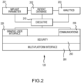
- An executive module 210 controls and oversees the use of other modules by providing services such as such a logon, logoff and module selection.
- a graphic user interface module 220 provides the displays and controls for the medical provider to interface with the application's modules.
- a communications module 230 When in range, such as during office visits or hospitalizations, a communications module 230 provides for computer instructions and data transfer between the medical provider software application 120 and the patient external controller 130 using encrypted transmissions over a standard communications network 122, such as Ethernet, USB drive, Bluetooth or Wi-Fi, as shown in Figure 1 .
- the communications module 230 may also retrieve implant performance data stored in the patient external controller 130.
- a security module 250 provides data encryption and medical provider authentication.
- a multiplatform interface module 260 provides application operation across different medical provider computing devices 121 with different screen sizes. All module software may be updated from time to time by the apparatus provider via disk and over the internet.
- a patient external controller 130 in communication with the medical provider software application 120 and the pump in reservoir implant 140, receives and stores inflation data and computer instruction updates from the medical provider software application 120, and sends data, power and computer instructions to the pump in reservoir implant 140. It also receives data back from the pump in reservoir implant 140 which may be viewed by the patient and stored for retransmission to the medical provider software application 120, thus allowing the patient to transdermally activate, control and power the implant and for the medical provider to reprogram and monitor implant usage and performance, respectively.
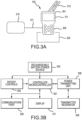
- Figure 3A illustrates an example of a hand-held patient external controller.
- the patient external controller includes an external controller case 301 with a touch screen display 311 and patient control 305 buttons.
- Patient controls 305 may be provided via push buttons, a touch screen display 311or both. They may include "On, Off, Inflate, and Deflate.” Multiple controls are provided for implants operating more than one inflatable medical implant 150.
- the buttons may control inflation and deflation of three inflatable medical implants 150.
- the center button is a "Power On and Off" button.
- the patient external controller 130 may also have a lanyard 312 which allows patients to hang the controller from the neck while in use. In operation, the patient may place the external controller case 301 or the transmitter resonator pad 310 on, or in proximity to, the dermis 101, over the pump in reservoir implant 140, and then operate the desired patient control 305.
- FIG. 3B is a block diagram representation of the patient external controller's130 electronic circuitry. It contains a rechargeable battery power source 304, such as Lithium Ion or Nickel Metal Hydride batteries, to power the apparatus. When not in use, the patient external controller 130 may sit in a battery charging station 302, which provides direct current power to charge the rechargeable battery power source 304. Overcurrent, short circuit and over temperature protection may be provided.
- the battery charging station 302 may be powered from 120-220 volt (V), 50-60 hertz (Hz) wall outlet connections or 12 V storage batteries.
- the rechargeable battery power source 304 supplies power to the patient external controller 130 to energize its functions and await commands from the patient via patient controls 305 or from the medical provider via the communications port 306.
- a signal is sent to a controller microcontroller 307, such as a TMS 320 series microcontroller, which contains a nonvolatile memory for storing its executable computer instructions, medical provider's settings, and implants usage data, to institute and control apparatus actions.
- a handshake is first conducted with the pump in reservoir implant140 over the bidirectional communications link132 to ensure it is ready for operation, and foreign object detection is initiated for safety.
- the controller microcontroller 307 connected to the power transmitting unit 308 over a standard bus, such as an I 2 C serial interface bus, sends handshake messages to the power transmitting unit 308 for transmission through the transmitter resonator 309 to pump in reservoir implant 140. Proper messages must be received back from the pump in reservoir implant 140 for the action to continue.
- the controller microcontroller 307 may be programmed to stop operation if the bidirectional communications link132 signal is lost, a preset pump in reservoir implant 140 safety parameter is exceeded, or a foreign object is detected.
- the controller microcontroller 307 may turn off power if no patient control 305 is received after a preset time interval.
- the power transmitting unit 308 Upon completion of the handshake and safety checks, the power transmitting unit 308 generates and transmits evanescent radio frequency transdermal power 131 via a transmitting resonator 309 to the pump in reservoir implant 130, and may operate in the 6 MHz to 7MHz band, a decade below the 63.87 MHz radio frequency of 1.5 tesla MRI machines.
- evanescent power transmission 131 may be used to transmit power to the pump in reservoir implant 140, as opposed to a close-coupled magnetic induction power transmission, because it provides more efficient, longer distance, higher power operation at a lower voltage.
- the transmitter resonator 309 may transmit over 5 watts of power, across more than 2-inchs of dermis 101, tissue and fat, to the pump in reservoir implant 140.
- the transmitter resonator 309 includes a wire coil and a matching capacitor network combination which resonates at the desired transmission frequency, such as 6.78 MHz.
- Wired coils may be located in both the patient external controller case 301 and in the transmitter resonator pad 310, which may make it easier for the patient to hold the wire coil on the skin over the implant.
- the transmitter resonator pad 310 may connect to the external controller case 301 via a plugin cable 311. Plugging the cable 311 into the external controller case 301 disconnects the case's wire coil.
- the pump in reservoir implant 140 includes an outer flexible reservoir case 141, which may be elliptical in shape and hold isotonic fluid 145 as the working fluid for inflatable medical implants 150.
- the inflatable medical implants may be penile cylinder implants, urethra cuff implants or anal cuff implants.
- the amount of isotonic fluid may depend on the implant and desired use. For example, 75 milliliters of isotonic fluid may be used with a penile cylinder implant.
- the pump in reservoir implant 140 further includes a pump package142, which may be in the form of a cylinder, 55 millimeters in diameter by 45 millimeters long and submerged in the isotonic fluid 145.
- a flexible tube 144 with a connector 146 carries the isotonic fluid 145 to and from inflatable medical implants 150.
- a pressure relief tube 143 is also included, should the apparatus fail.
- the reservoir case 141 may have a biologically inert outer wall with an insulating material, such as Nomex, molded into the wall to reduce heat transfer rate from the isotonic fluid to the patient during low duty cycle inflation and deflation.
- the unfilled reservoir may be folded into a cylindrical shape to ease insertion by the surgeon.
- the surgeon may insert the reservoir case 141 into the patient's abdomen 102 and then fill it with isotonic fluid 145.
- the isotonic fluid 145 is the pump's operating fluid, provides a heat sink for the pump package142, and does not change the patient's local electrolytic balance should leakage occur.
- the apparatus may inflate and deflate any combination of penile cylinder implants 417, urethra cuff implants 418, anal cuff implants 419, and other inflatable medical implants.
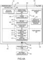
- Figure 4A illustrates a pump in reservoir implant 140 operating a single inflatable medical implant 150.
- Figure 4B shows a pump in reservoir implant 140 operating three inflatable medical implants: a penile cylinder implant 417, a urethra cuff implant 418, and an anal cuff implant 419.
- the pump in reservoir implant 140 may be MR-Conditional or MR-Safe, with components that may not translate, rotate, excessively heat or cause MRI picture distortion when introduced into certain MRI machines. As shown in Figure 6 , the pump in reservoir implant 140 may also be implemented with components which contain MR-Unsafe ferrous materials.
- the MR-Safe or MR-Conditional pump in reservoir implant 140 apparatus may inflate and deflate penile cylinder implants 417.
- the pump may pump 60 milliliters of fluid at 25 pounds per square inch pressure in 45 seconds, which includes a safety factor. Pumping equations show that this is equivalent to providing 0.23 watts of pumping power at the penile cylinder implant 417. Since cuffs require less than 1/10 th the amount of fluid transfer than for cylinders, requirements are less stringent for these implants.
- MR-Unsafe ferrous brushed direct current and brushless direct current electric motors coupled to ferrous containing positive displacement internal gear pumps, which meet these requirements, may be used. These motors use ferrous materials to greatly increase torque by linking magnetic flux between the motor's stator and rotor such that very little leakage flux is generated. For such motors, removing ferrous materials for MRI safety reduces flux linkages, thereby greatly reducing torque and power output. In such motors, some torque can be bought back by increasing motor diameter and applied voltage. However, minimizing these parameters is desirable.
- a nonferrous combination of a 3-phase squirrel cage motor and positive displacement internal gear pump may also be used.
- a 50,000 revolutions per minute motor, reduction gear and low speed pump combination 10 millimeters in diameter, may be used.
- a nonferrous 50 millimeter diameter squirrel cage motor 409 operating at 4000 revolutions per minute, power by a 24 volt direct current input 3-phase power inverter 408 and driving a 10 millimeter diameter nonferrous positive displacement internal gear pump 410 may be used.
- An electrically operated, nonferrous piezoelectric valve 411 may be added at the internal gear pump 410 connection with the inflatable medical implant 150 to prevent fluid leakage back to the reservoir through the pump, and vice versa. Individually operating a stack of such valves allows a single motor and pump to operate multiple inflatable medical implants, providing a significant cost and size saving. Less than 5 watts of transdermal power is needed to power the pump in reservoir implant.
- a reservoir case 141 contains a pump package 142 which includes a transdermal power receiver resonator 403; electrical components mounted on circular circuit boards 440; a nonferrous pump assembly, comprising a 3-phase squirrel cage motor 409, an internal gear pump 410, a piezoelectric valve 411; and pump speed and pressure sensors 412, all submerged in an isotonic fluid 145.
- a pump package 142 which includes a transdermal power receiver resonator 403; electrical components mounted on circular circuit boards 440; a nonferrous pump assembly, comprising a 3-phase squirrel cage motor 409, an internal gear pump 410, a piezoelectric valve 411; and pump speed and pressure sensors 412, all submerged in an isotonic fluid 145.
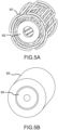
- Figures 5A and 5B illustrate a squirrel cage motor, supplied with 3-phase alternating current power, and able to be operated at various speeds.
- a 50 millimeter diameter by 25 millimeter long, 3-phase 4-pole squirrel cage motor supplied with 3-phase 14.9 volts alternating current power, and operating at 4,000 revolutions per minute, may be used.
- Figure 5A shows the motor's 4-pole stator windings 501 and the rotor bars 502 with their short circuiting endplates.
- the stator windings 501 and the rotor bars 502 are encapsulated in molded plastic to reduce windage losses and to stabilize the rotor under centrifugal force.
- a 3-phase squirrel cage motor has the advantages of small size, self-starting, high speed operation. Squirrel cage motors do not use brushes or slip rings, wear items which reduce motor life.
- the submerged squirrel cage motor 409 drives a submerged nonferrous, positive displacement rotary internal gear pump 410, where one pump orifice is open to the reservoir through the reservoir orifice tube 810.
- the nonferrous internal gear pump may be 10 millimeters in diameter and 10 millimeters long and have shaft seals to prevent fluid from entering the squirrel cage motor 409.
- the other internal gear pump 410 orifice may be assembled to a 10 millimeter diameter nonferrous piezoelectric valve 411 orifice. The valve is closed when not in use to prevent leakage of fluid through the internal gear pump 410.
- An external orifice tube 800 connects the piezoelectric valve's 411other orifice to a connector 146 placed through the reservoir case 141for attachment of the flexible tube 144 during surgery when the surgeon threads the flexible tube 144 from the reservoir case 141 to the inflatable medical implant 150 and connects it to the pump in reservoir implant using connector 146.
- Figure 4B shows individually controlled piezoelectric stacked valves 420 operating three implants: a dual penile cylinder implant 417, a urethra cuff implant 418 and an anal cuff implant 419.
- a computer interlock is provided so only one valve can be open at a time.
- Implant electronics driving the pump 441 may be housed on military-grade, multilayer, coated circular circuit boards 440 for physical damage and short circuit protection and moisture-proofing.
- the circular circuit boards 440 may be 50 millimeters in diameter and have holes in their centers for placement around the 10 millimeter diameter internal gear pump 410 and piezoelectric valve 411.
- the boards and their components are, at least, MR-Conditional and may be MR-Safe.
- the receive resonator 403 may receive evanescent power transmissions 131 transdermally from the transmitting resonator 309. Additionally, it may be used for the bidirectional communication link 132 with the patient external controller 130.
- the bidirectional communications unit 404 codes and decodes these bidirectional signals for the implant microcontroller 406.
- the receiver resonator 403 includes a resonant circuit made up of an nonferrous wire coil 700 inductor, which may be in the shape of a 45 millimeter diameter circle, and a MRI filter/matching network 701, which may resonate at 6.78MHz and filter out the higher frequency transmissions of MRI machines, such as 63.9 MHz from 1.5 tesla MRI machines.
- the wire coil 700 may be etched onto the circular circuit board 440, molded into the reservoir case 141, or housed in a separate case which, in obese patients, may be located under the dermis 101.
- the receiver resonator's 403 output voltage may vary widely from patient to patient with placement of the transmitter resonator 309 with respect to coil 700.
- the receiver resonator 403 feeds alternating current power to a power conditioning unit 405, which converts the varying received alternating current voltage to stable direct current voltages for the electronics, motor and sensors.
- a low power low voltage power supply may generate 5 volts direct current to power the electronic components and sensors.
- the power conditioning unit 405 may use Schottky diodes in a full wave bridge rectifier 710 configuration to convert the alternating current voltage into direct current.
- An electromagnetic interference filter 711 is applied to remove diode switching transient noise.
- a low voltage switch mode power supply 712 may provide stable 5 volts direct current.
- the low voltage switch mode power supply 712 may contain an under voltage-over voltage protection circuit which only energizes the switch mode power supply when appropriate direct current voltage appears at its input to produce its desired output. Switch mode power supplies obviate the need for inefficient linear regulators and are more efficient than voltage feedback loops to the patient external controller 130.
- an implant microcontroller 406 Upon reception of power from the low voltage switch mode power supply 712, an implant microcontroller 406 is energized, does a handshake with the patient external controller 130 and self-tests for problems in the pump in reservoir implant 130, such as out of range temperature and pressure and electric current leakage. The implant microcontroller 406 then sends status data back to the patient external controller 130, which, if all is well, energizes the patient controls 305.
- the implant microcontroller 406 such as a MR-Safe MSP430 or C2000 series microcontroller, may contain an encrypted nonvolatile memory, a reduced instruction set computer, a pulse width modulation unit, at least one analog-to-digital converter, at least one data bus, and self-test capability.
- the implant microprocessor 406 may turn on a gallium nitride transistor, programmable totem pole boost power converter 713 to generate stable high voltage direct current 140, such as 24 volts direct current.
- the gallium nitride transistor, programmable totem pole power converter 713 uses gallium nitride high electron mobility field effect transistor switches, which achieve lower losses than silicon-based components, to nominally provide 24 volts direct current to power the 3-power inverter 408 for the 3-phase squirrel cage motor 409.
- the gallium nitride transistor, totem pole boost power converter 713 operates at a lower input voltage, such as 12 volts direct current, than its output voltage, thereby allowing for lower evanescent power transmission 131 voltage from a lower voltage rechargeable battery power source 304, for example 12 volts direct current, in the patient external controller 130, which results in less cost and greater patient safety.
- the implant microcontroller 406 uses the pulse width modulation voltage control 714 path to sense the alternating current input voltage, determines when that voltage crosses zero and then sends pulse width modulation signals to turn on and turn off gallium nitride half-bridge transistors in an inductive boost converter configuration to achieve alternating current to direct current boost conversion to provide the high direct current voltage power 420.
- the high direct current voltage power 420 voltage is fed back to the implant microprocessor 406 for closed loop control of the voltage by varying the pulse width modulation.
- the high voltage direct current 420 output of the gallium nitride transistor, programmable totem pole power converter 713 is then inverted to 3-phase alternating current by a 3-phase power inverter 408 controlled by the implant microcontroller 406.
- the frequency and the number of sinusoidal cycles to be generated may be set from the medical provider software application 120.
- the implant microcontroller 406's pulse width modulation unit operating at 50KHz, may generate three 200 Hz pulse width modulation sinusoids set 120 degrees apart for low harmonic distortion losses.
- Soft pulse width modulation gallium nitride transistor startup is used to decrease losses from transistor switching transients. Motor direction, and therefore inflatable medical implant 150 inflation or deflation, is achieved by switching two phases of the three 3-phase signals.
- the sinusoidal pulse width modulation signals are input to three 3-phase half-bridge gate drivers 720, which, in turn, drive three 3-phase half control bridges 721, to generate 3-phase power to drive the motor.
- Current and voltage feedback 722 from the 3-phase half control bridges 721 is used in the implant microcontroller 406 to provide stable operation of this nonferrous low stator impedance motor, and detect faults for safe operation.
- the motor which drives the pump, sees a varying load.
- the pump sees high pressure at its input and low pressures is at its output and requires reduced motor torque, and therefore power, to operate.
- Efficiency of the pump and motor combination is achieved by calculating and applying the optimum 3-phase voltage at the optimum 3-phase frequency continuously over the pumping cycle. This optimization may be achieved by the implant microprocessor 406 using the pulse width modulation voltage control 714 feedback loop and the current and voltage feedback 722 loop to set the high direct current voltage 420 and the 3-Phase pulse width modulation signal 723 to control the 3-phase squirrel cage motor's 409 speed and torque.
- the gallium nitride transistor, programmable totem pole boost power converter 713 may be replaced by a Schottky diode full wave bridge rectifier and electromagnetic interference filter, and the varying high direct current voltage power 420 is fed directly to the 3-phase half control bridges 721, which act as both a voltage regulator and a direct current to alternating current inverter.
- the implant microprocessor then generates the correct pulse width modulation signals for the varying high direct current voltage power 420 when it computes the pulse width modulation signals for the 3-phase squirrel cage motor 409. Additionally it provides over and under voltage protection for the varying high direct current voltage power 420.
- the implant microcontroller 406 also receives, processes, and formats implant performance and safety data for transmission to the patient external controller 130. In some implementations, additional analog-to-digital and digital-to-analog integrated circuit are necessary to handle all the sensor data.
- Pump pressure and motor speed sensors 412 are provided along with reservoir pressure and temperature sensors 414. Pressure and speed data is sent to the implant microcontroller 406. The pressure and speed data may be used for automatic cutoff should the pump run over or under speed limits, or on the occurrence of leakage, over inflation or a fluid blockage.
- the pressure and speed data may also be used to help the medical provider set the amount of fluid to be transferred that is best suited for the patient.
- Reservoir pressure and temperature sensors 413 may be included on the circular circuit boards 440 to send pressure and temperature data to the implant microcontroller 406 for high temperature cutoff should the isotonic fluid 145 overheat.
- integrated circuit chips used in the power receiving unit 405 and implant microcontroller 406 may have internal temperatures sensors that turn off the chip in over temperature situations.
- a pressure relief tube143 is provided to allow medical providers to manually deflate the inflatable medical implant 150 by inserting a small bore hypodermic needle into the pressure relief tube143 and draw out the inflating fluid.
- One end of the tube is located at the inflatable medical implant 150 and the other end just below the dermis 101.
- Figure 6 shows a diagram of a MR-Unsafe pump in reservoir implant implementation.
- the implementation of Figure 6 includes many of the same components already described in Figures 4A and 4B .
- the 3-phase power inverter and nonferrous pump and motor 408, 409, 410, from Figures 4A and 4B are replaced by an inflate-off-deflate switch 608, direct current motor 609 and internal gear pump 610.
- Coupling between the direct current motor 609 and the internal gear pump 610 may be magnetic, allowing the pump to be in submerged in the isotonic fluid 145 without the need for seals in the pump, thereby increasing efficiency and reliability.
- the 3-phase power inverter 408 is replaced by connecting the 713 gallium nitride transistor, programmable totem pole boost power converter's 713 high direct current voltage power 420 through an implant microcontroller 406 controlled half-bridge reversing direct current power control inflate-off-deflate switch 608, to turn the motor on and off and to reverse its direction.
- Figure 8 shows the pump package142 illustrating the circular circuit board 440, squirrel cage motor 409 and piezoelectric valve 411 arrangement.
- an internal gear pump orifice 410 directly connects to a piezoelectric valve 411 orifice.
- a reservoir orifice tube 810 then connects the other internal gear pump 410 orifice to inside the reservoir case 141 in contact with the isotonic fluid 145.
- An external orifice tube 800 connects the other piezoelectric valve's 411 orifice to a connector 146 leading outside of the reservoir case 141.
- the figure also shows a single circular circuit board 440 mounted around a piezoelectric valve 411.
- this apparatus may provide vibrating penile cylinder implants 417 by modulating the implant microcontroller's 406 3-phase pulse width modulation signal, or by adding a pressure transducer and audio power amplifier (not shown) in fluid communications with an inflatable penile implant's input flexible tube.
Landscapes
- Health & Medical Sciences (AREA)
- Engineering & Computer Science (AREA)
- Power Engineering (AREA)
- Animal Behavior & Ethology (AREA)
- Public Health (AREA)
- Oral & Maxillofacial Surgery (AREA)
- Biomedical Technology (AREA)
- Heart & Thoracic Surgery (AREA)
- Vascular Medicine (AREA)
- Life Sciences & Earth Sciences (AREA)
- Cardiology (AREA)
- General Health & Medical Sciences (AREA)
- Transplantation (AREA)
- Veterinary Medicine (AREA)
- Urology & Nephrology (AREA)
- Computer Networks & Wireless Communication (AREA)
- Reproductive Health (AREA)
- Electromagnetism (AREA)
- Physics & Mathematics (AREA)
- Prostheses (AREA)
- External Artificial Organs (AREA)
Claims (21)
- Pumpe-im-Behälter-Implantat (140) zum Aufblasen mindestens eines aufblasbaren medizinischen Implantats (150), wobei das Pumpe-im-Behälter-Implantat umfasst: ein Behältergehäuse (141), das so konfiguriert ist, dass es isotonisches Fluid (145) als das Arbeitsfluid für das mindestens eine aufblasbare medizinische Implantat (150) enthält, und ein Pumpenpaket (142), das in dem Behältergehäuse (141) enthalten ist, wobei das Pumpenpaket (142) umfasst: mindestens einen nicht-eisenhaltigen Motor (409); eine nicht-eisenhaltige Flüssigkeitspumpe (410), die mit dem mindestens einen nicht-eisenhaltigen Motor verbunden ist; und mindestens ein nicht-eisenhaltiges Ventil (411), das mit der nicht-eisenhaltigen Flüssigkeitspumpe (410) verbunden ist und so konfiguriert ist, dass es den Durchgang von Flüssigkeit von der Pumpe (410) zu dem mindestens einen aufblasbaren medizinischen Implantat (150) ermöglicht, wobei eine interne Zahnradpumpenöffnung, die direkt mit einer piezoelektrischen Ventilöffnung verbunden ist, das mindestens eine nicht-eisenhaltige Ventil (411) und die nicht-eisenhaltige Flüssigkeitspumpe (410) verbindet; ein Reservoiröffnungsrohr (810), das die Öffnung einer anderen Innenzahnradpumpe mit der Innenseite des Reservoirgehäuses (141) in betriebsbereitem Kontakt mit der isotonischen Flüssigkeit verbindet; und ein Außenöffnungsrohr (800), das die Öffnung eines anderen piezoelektrischen Ventils mit einem Anschluss (146) verbindet, der aus dem Reservoirgehäuse (141) herausführt.
- Pumpe im Reservoir-Implantat (140) nach Anspruch 1, wobei mindestens ein Nichteisen-Motor (409) einen 3-Phasen-Nichteisen-Induktions- oder -Synchronmotor umfasst; wobei die Nichteisen-Fluidpumpe (410) eine Nichteisen-Zahnradpumpe umfasst; und wobei das mindestens eine Nichteisen-Ventil (411) mehrere, unabhängig voneinander elektrisch gesteuerte piezoelektrische Nichteisen-Fluidventile (420) umfasst, die eine unabhängige Steuerung des mindestens einen aufblasbaren medizinischen Implantats (150) erreichen.
- Pumpe-im-Behälter-Implantat (140) nach Anspruch 1 oder 2, wobei die Pumpe-im-Behälter-Implantat (140) so konfiguriert ist, dass sie das mindestens eine aufblasbare medizinische Implantat (150) innerhalb eines vorbestimmten Zeitraums aufbläst und entleert, indem sie das isotonische Fluid (145) mit einem bestimmten oder variierenden Druck überträgt; und wobei eine Energieübertragungseinheit (308) so konfiguriert ist, dass sie Energie zum Aufblasen des mindestens einen aufblasbaren medizinischen Implantats überträgt.
- Das Pumpe-im-Behälter-Implantat (140) nach einem der vorangehenden Ansprüche, wobei das Pumpe-im-Behälter-Implantat (140) MR-sichere Materialien ohne Untersetzungsgetriebe umfasst; und der mindestens eine Nichteisenmotor (409) ferner einen Nichteisen-Käfigmotor umfasst, der so konfiguriert ist, dass er den Wirkungsgrad der Motor-Pumpe erhöht und den Motordurchmesser ohne Verwendung von Untersetzungsgetrieben verringert.
- Transdermal angetriebenes, aufblasbares medizinisches Implantatsystem, umfassend: ein Pumpe-im-Reservoir-Implantat (140) nach einem der vorangehenden Ansprüche, wobei das Reservoir-Gehäuse (141) ein biologisch kompatibles, fluiddichtes Reservoir-Gehäuse ist, das ein isotonisches Fluid (145) enthält; wobei das in das Reservoirgehäuse (141) eingetauchte Pumpenpaket (142) mindestens eine Leiterplatte (440), mindestens einen Motor (409), mindestens eine Pumpe (410), mindestens ein Ventil (411), mindestens einen Drucksensor (412) und mindestens einen Temperatursensor (414) umfasst; mindestens einen flexiblen Schlauch; und das Pumpe-im-Reservoir-Implantat mindestens ein aufblasbares medizinisches Implantat umfasst, das durch den flexiblen Schlauch (144) in Fluidverbindung mit dem Pumpe-im-Reservoir-Implantat steht.
- Das aufblasbare medizinische Implantat-Aufblassystem nach Anspruch 5 umfasst ferner einen Induktor mit gewundener Schleife und ein Anpassungsnetzwerk, das so konfiguriert ist, dass es einen transdermalen Resonanzempfang von elektromagnetischer Hochfrequenzfeldenergie ermöglicht, um das mindestens eine aufblasbare medizinische Implantat (150) direkt aufzublasen.
- Das aufblasbare medizinische Implantataufblassystem nach Anspruch 5 oder 6, das ferner eine Stromversorgungseinheit umfasst, die Folgendes enthält: eine Niederspannungsstromversorgung, die mit einem Spulen- und Anpassungsnetzwerk in Verbindung steht, wobei die Niederspannungsstromversorgung einen Schottky-Dioden-Vollwellengleichrichter, einen elektromagnetischen Interferenzfilter und ein Schaltnetzteil enthält, um Niederspannungsgleichstrom zur Versorgung elektronischer Schaltungen zu erzeugen; und eine Hochspannungsstromversorgung, die mit einem Spulen- und Anpassungsnetzwerk in Verbindung steht, wobei die Hochspannungsstromversorgung einen brückenlosen Galliumnitridtransistor, einen programmierbaren Totempol-Aufwärtswandler enthält, der so konfiguriert ist, dass er empfangene Hochfrequenzspannung in stabilen Gleichstrom höherer Spannung umwandelt.
- Das aufblasbare medizinische Implantat-Aufblassystem nach Anspruch 7, das ferner einen Implantat-Mikrocontroller umfasst, der mit der Niederspannungsstromversorgung in Verbindung steht, wobei der Implantat-Mikrocontroller mindestens einen Computer, mindestens einen nichtflüchtigen Speicher, mindestens eine Pulsbreitenmodulationseinheit und mindestens einen Analog-Digital-Wandler umfasst.
- Das aufblasbare medizinische Implantat-Aufblassystem nach Anspruch 7 oder 8, das ferner einen Leistungsinverter umfasst, der in elektrischer Verbindung mit der Niederspannungs-Stromversorgung, der Hochspannungs-Stromversorgung und der Pulsbreitenmodulationseinheit steht, wobei der Leistungsinverter eine Galliumnitrid- oder Metall-auf-Halbleiter-Feldeffekttransistor-3-Phasen-Halbbrückenschaltung umfasst, um Hochspannungs-Gleichstrom in eine 3-Phasen-Pulsbreitenmodulations-Wechselspannung umzuwandeln, um einen 3-Phasen-Induktionsmotor zu steuern.
- Aufblasbares medizinisches Implantat-Aufblassystem nach einem der Ansprüche 7 bis 9, das ferner einen Wechselrichter umfasst, der mit der Niederspannungsstromversorgung und der Pulsweitenmodulationseinheit in elektrischer Verbindung steht und so konfiguriert ist, dass er schwankenden Hochspannungsgleichstrom direkt regelt und in eine stabile 3-Phasen-Pulsweitenmodulations-Wechselspannung umwandelt, um einen 3-Phasen-Induktionsmotor anzutreiben.
- Aufblasbares medizinisches Implantataufblassystem nach einem der Ansprüche 5 bis 10, wobei die mindestens eine Leiterplatte zertifizierbare MR-konforme elektronische Leiterplatten mit darauf montierten elektronischen Komponenten umfasst, die zum Schutz vor Feuchtigkeit und zur Stabilität beschichtet sind.
- Aufblasbares medizinisches Implantatsystem nach einem der Ansprüche 5 bis 11, wobei die mindestens eine Leiterplatte mindestens eine kreisförmige Leiterplatte mit dem gleichen Durchmesser wie der mindestens eine Motor umfasst, wobei die mindestens eine kreisförmige Leiterplatte eine Bohrung in ihrer Mitte aufweist.
- Das aufblasbare medizinische Implantat-Aufblassystem nach einem der Ansprüche 5 bis 12, das ferner einen Spannungssensor in elektrischer Verbindung mit einem Mikrocontroller umfasst, wobei der Mikrocontroller so konfiguriert ist, dass er: die Daten von den Druck-, Spannungs- und Temperatursensoren für die Rückkopplungssteuerung der 3-Phasen-Pulsbreitenmodulationssignale verwendet, um den Motorbetrieb während eines Pumpzyklus zu optimieren; und die Daten von den Druck-, Spannungs- und Temperatursensoren für die Erfassung von Implantatfehlern einschließlich Motorunter- und -überdrehzahl, Unter- und Überstrom und -spannung, Flüssigkeitsleckagen, Kurzschlüsse, Überdruck und Übertemperatur verwendet.
- Aufblasbares medizinisches Implantatsystem nach einem der Ansprüche 5 bis 13, das ferner einen Druckentlastungsschlauch umfasst, der in Fluidverbindung mit dem mindestens einen aufblasbaren medizinischen Implantat steht.
- Aufblasbares medizinisches Implantat-Aufblassystem nach einem der Ansprüche 5 bis 14, ferner umfassend eine externe Patientensteuerung (130), die Folgendes umfasst: eine Energiequelle zum Betreiben der externen Patientensteuerung und der Pumpe im Reservoir-Implantat; Patientensteuerungen; eine Anzeige; einen Mikrocontroller in elektrischer Kommunikation mit den Patientensteuerungen und der Anzeige; einen verschlüsselten, nicht zerstörbaren Computerspeicher in elektrischer Kommunikation mit dem Mikrocontroller, wobei der fir.einen verschlüsselten, zerstörungsfreien Computerspeicher, der Computeranweisungen, Aufblasparameter der Pumpe im Reservoir und Sicherheitsdaten zur Übertragung an das Implantat der Pumpe im Reservoir sowie Betriebsparameter speichert, die von dem Implantat der Pumpe im Reservoir empfangen werden, um einen Betriebsverlauf zu erstellen; einen Wechselstrom-Resonanzstromsender in elektrischer Kommunikation mit dem Mikrocontroller und in drahtloser Kommunikation mit dem Implantat der Pumpe im Reservoir; eine bidirektionale Hochfrequenzverbindung in elektrischer Kommunikation mit dem Mikrocontroller und in drahtloser Kommunikation mit dem Pumpe-im-Behälter-Implantat, die so konfiguriert ist, dass sie Computerbefehle, Steuersignale und Daten zu und von dem Pumpe-im-Behälter-Implantat überträgt; und eine Kommunikationsschnittstelle in Kommunikation mit einer Softwareanwendung eines medizinischen Anbieters, die so konfiguriert ist, dass sie Computerbefehle und Steuerdaten von der Softwareanwendung des medizinischen Anbieters überträgt und Betriebsverlaufsdaten der Pumpe-im-Behälter zurück an die Softwareanwendung des medizinischen Anbieters überträgt.
- Aufblasbares medizinisches Implantatsystem nach Anspruch 15, wobei die Kommunikationsschnittstelle so konfiguriert ist, dass sie Anweisungen von der Softwareanwendung des medizinischen Dienstleisters empfängt, um das mindestens eine aufblasbare medizinische Implantat (150) zu betreiben.
- Aufblasbares medizinisches Implantatsystem nach Anspruch 15 oder 16, umfassend: eine Datenrückkopplungsschleife von der externen Patientensteuerung zur Softwareanwendung des medizinischen Dienstleisters, die Patienten- und aufblasbare medizinische Implantatdaten einschließlich Flüssigkeitsdruck, Zeit zwischen Operationen und Pumpenbetriebszeit empfängt; und ein Analysemodul, wobei der medizinische Dienstleister empfangene Patientendaten analysieren kann, um Leistungstrends für aufblasbare medizinische Implantate über Patienten und Geräte hinweg zu bestimmen und festzustellen, dass ein bestimmtes Gerät kurz vor dem Ausfall steht.
- Aufblasbares medizinisches Implantatsystem nach einem der Ansprüche 15 bis 17, das ferner ein Sicherheitssystem für die Hochfrequenz-Energieübertragung umfasst, bei dem keine Hochspannung von der externen Patientensteuerung übertragen wird, bis ein Handshake mit der Pumpe im Reservoirimplantat abgeschlossen ist, keine Fehler in der Pumpe im Reservoirimplantat erfasst werden und ein Fremdkörpererfassungsprozess erfolgreich abgeschlossen ist.
- Aufblasbares medizinisches Implantatsystem nach einem der Ansprüche 5 bis 18, das ferner ein Resonatorpolster mit einer Spule umfasst, die in elektrischer Verbindung mit einem Hochfrequenzanpassungsnetzwerk und einem Leistungssender und in drahtloser Verbindung mit der Pumpe im Reservoirimplantat steht.
- Aufblasbares medizinisches Implantatsystem nach einem der Ansprüche 5 bis 19, wobei das mindestens eine aufblasbare medizinische Implantat eine Analmanschette und eine Harnröhrenmanschette umfasst und wobei ein Mikrocontroller so konfiguriert ist, dass er den Druck während Zeiten geringer Patientenaktivität senkt.
- Aufblasbares medizinisches Implantatsystem nach einem der Ansprüche 5 bis 20, wobei das mindestens eine aufblasbare medizinische Implantat ein aufblasbares Penisimplantat ist und ferner einen Druckwandler und einen Audio-Leistungsverstärker umfasst, die in Fluidverbindung mit dem aufblasbaren Penisimplantat stehen.
Priority Applications (1)
| Application Number | Priority Date | Filing Date | Title |
|---|---|---|---|
| EP24197138.1A EP4445877A3 (de) | 2018-05-04 | 2019-05-01 | Transdermal betriebenes mr-konditioniertes medizinisches implantataufblassystem |
Applications Claiming Priority (2)
| Application Number | Priority Date | Filing Date | Title |
|---|---|---|---|
| US15/971,312 US11051923B2 (en) | 2015-09-18 | 2018-05-04 | Transdermally powered MR-conditional medical implant inflator system |
| PCT/US2019/030174 WO2019213236A1 (en) | 2018-05-04 | 2019-05-01 | Transdermally powered mr-conditional medical implant inflator system |
Related Child Applications (2)
| Application Number | Title | Priority Date | Filing Date |
|---|---|---|---|
| EP24197138.1A Division EP4445877A3 (de) | 2018-05-04 | 2019-05-01 | Transdermal betriebenes mr-konditioniertes medizinisches implantataufblassystem |
| EP24197138.1A Division-Into EP4445877A3 (de) | 2018-05-04 | 2019-05-01 | Transdermal betriebenes mr-konditioniertes medizinisches implantataufblassystem |
Publications (3)
| Publication Number | Publication Date |
|---|---|
| EP3787552A1 EP3787552A1 (de) | 2021-03-10 |
| EP3787552A4 EP3787552A4 (de) | 2022-06-15 |
| EP3787552B1 true EP3787552B1 (de) | 2024-11-06 |
Family
ID=68386080
Family Applications (2)
| Application Number | Title | Priority Date | Filing Date |
|---|---|---|---|
| EP24197138.1A Withdrawn EP4445877A3 (de) | 2018-05-04 | 2019-05-01 | Transdermal betriebenes mr-konditioniertes medizinisches implantataufblassystem |
| EP19796316.8A Active EP3787552B1 (de) | 2018-05-04 | 2019-05-01 | Transdermal betriebenes mr-conditional medizinisches implantataufblassystem |
Family Applications Before (1)
| Application Number | Title | Priority Date | Filing Date |
|---|---|---|---|
| EP24197138.1A Withdrawn EP4445877A3 (de) | 2018-05-04 | 2019-05-01 | Transdermal betriebenes mr-konditioniertes medizinisches implantataufblassystem |
Country Status (3)
| Country | Link |
|---|---|
| EP (2) | EP4445877A3 (de) |
| KR (1) | KR20210005223A (de) |
| WO (1) | WO2019213236A1 (de) |
Families Citing this family (3)
| Publication number | Priority date | Publication date | Assignee | Title |
|---|---|---|---|---|
| US20200222188A1 (en) * | 2019-01-14 | 2020-07-16 | Boston Scientific Scimed, Inc. | Pump and valve system for hydraulic pressurization of implants |
| JP2025500811A (ja) * | 2021-12-21 | 2025-01-15 | ボストン サイエンティフィック サイムド,インコーポレイテッド | 電子埋込可能陰茎プロテーゼ |
| US20230270553A1 (en) * | 2022-01-19 | 2023-08-31 | Boston Scientific Scimed, Inc. | Implantable inflatable device and therapeutic methods |
Family Cites Families (9)
| Publication number | Priority date | Publication date | Assignee | Title |
|---|---|---|---|---|
| ATE324087T1 (de) * | 2000-02-14 | 2006-05-15 | Potencia Medical Ag | Männliche impotentzprothesevorrichtung mit drahtloser energieversorgung |
| US7390294B2 (en) * | 2004-05-28 | 2008-06-24 | Ethicon Endo-Surgery, Inc. | Piezo electrically driven bellows infuser for hydraulically controlling an adjustable gastric band |
| US7775966B2 (en) * | 2005-02-24 | 2010-08-17 | Ethicon Endo-Surgery, Inc. | Non-invasive pressure measurement in a fluid adjustable restrictive device |
| US8118750B2 (en) * | 2005-10-21 | 2012-02-21 | Medtronic, Inc. | Flow sensors for penile tumescence |
| EP3085402B1 (de) * | 2009-12-31 | 2018-05-09 | DEKA Products Limited Partnership | Infusionspumpenanordnung |
| US20120059216A1 (en) * | 2010-09-07 | 2012-03-08 | Allergan, Inc. | Remotely adjustable gastric banding system |
| US9884180B1 (en) * | 2012-09-26 | 2018-02-06 | Verily Life Sciences Llc | Power transducer for a retinal implant using a contact lens |
| US20140277467A1 (en) * | 2013-03-14 | 2014-09-18 | Spinal Stabilization Technologies, Llc | Prosthetic Spinal Disk Nucleus |
| US10383715B2 (en) * | 2015-09-18 | 2019-08-20 | Mhn Biotech Llc | Transdermally powered electric pump in reservoir inflator for inflatable medical implants |
-
2019
- 2019-05-01 EP EP24197138.1A patent/EP4445877A3/de not_active Withdrawn
- 2019-05-01 EP EP19796316.8A patent/EP3787552B1/de active Active
- 2019-05-01 KR KR1020207034563A patent/KR20210005223A/ko active Pending
- 2019-05-01 WO PCT/US2019/030174 patent/WO2019213236A1/en not_active Ceased
Also Published As
| Publication number | Publication date |
|---|---|
| EP4445877A3 (de) | 2024-12-18 |
| KR20210005223A (ko) | 2021-01-13 |
| WO2019213236A1 (en) | 2019-11-07 |
| EP3787552A1 (de) | 2021-03-10 |
| EP4445877A2 (de) | 2024-10-16 |
| EP3787552A4 (de) | 2022-06-15 |
Similar Documents
| Publication | Publication Date | Title |
|---|---|---|
| US11554002B2 (en) | Transdermally powered MR-conditional medical implant inflator system | |
| CN102149425B (zh) | 用于植入医疗设备的tet系统 | |
| EP1609501B1 (de) | Medizinisches Implantat mit einer Schaltung zur transkutanen Energieübertragung mit geschlossenem Kreislauf zur Übertragungsleistungssteuerung | |
| US11969328B2 (en) | Transdermally powered MR-conditional medical implant inflator system | |
| EP3787552B1 (de) | Transdermal betriebenes mr-conditional medizinisches implantataufblassystem | |
| US9308303B2 (en) | Transcutaneous power transmission and communication for implanted heart assist and other devices | |
| EP2538896B1 (de) | Induktiv betriebenes ferneinstellbares magenbandsystem | |
| CN105797227A (zh) | 一种植入式心室辅助装置及供电方法 | |
| WO2023225715A1 (en) | An apparatus and method for transmitting power and data across the skin to implantable medical devices | |
| CN116808429A (zh) | 一种非血液接触式磁动力心室辅助装置 |
Legal Events
| Date | Code | Title | Description |
|---|---|---|---|
| STAA | Information on the status of an ep patent application or granted ep patent |
Free format text: STATUS: THE INTERNATIONAL PUBLICATION HAS BEEN MADE |
|
| PUAI | Public reference made under article 153(3) epc to a published international application that has entered the european phase |
Free format text: ORIGINAL CODE: 0009012 |
|
| STAA | Information on the status of an ep patent application or granted ep patent |
Free format text: STATUS: REQUEST FOR EXAMINATION WAS MADE |
|
| 17P | Request for examination filed |
Effective date: 20201102 |
|
| AK | Designated contracting states |
Kind code of ref document: A1 Designated state(s): AL AT BE BG CH CY CZ DE DK EE ES FI FR GB GR HR HU IE IS IT LI LT LU LV MC MK MT NL NO PL PT RO RS SE SI SK SM TR |
|
| AX | Request for extension of the european patent |
Extension state: BA ME |
|
| DAV | Request for validation of the european patent (deleted) | ||
| DAX | Request for extension of the european patent (deleted) | ||
| RIC1 | Information provided on ipc code assigned before grant |
Ipc: A61F 2/48 20060101ALI20211223BHEP Ipc: A61F 2/26 20060101ALI20211223BHEP Ipc: A61F 2/00 20060101ALI20211223BHEP Ipc: A61F 2/02 20060101AFI20211223BHEP |
|
| A4 | Supplementary search report drawn up and despatched |
Effective date: 20220517 |
|
| RIC1 | Information provided on ipc code assigned before grant |
Ipc: A61F 2/48 20060101ALI20220511BHEP Ipc: A61F 2/26 20060101ALI20220511BHEP Ipc: A61F 2/00 20060101ALI20220511BHEP Ipc: A61F 2/02 20060101AFI20220511BHEP |
|
| GRAP | Despatch of communication of intention to grant a patent |
Free format text: ORIGINAL CODE: EPIDOSNIGR1 |
|
| STAA | Information on the status of an ep patent application or granted ep patent |
Free format text: STATUS: GRANT OF PATENT IS INTENDED |
|
| INTG | Intention to grant announced |
Effective date: 20240617 |
|
| GRAS | Grant fee paid |
Free format text: ORIGINAL CODE: EPIDOSNIGR3 |
|
| P01 | Opt-out of the competence of the unified patent court (upc) registered |
Free format text: CASE NUMBER: APP_48172/2024 Effective date: 20240821 |
|
| GRAA | (expected) grant |
Free format text: ORIGINAL CODE: 0009210 |
|
| STAA | Information on the status of an ep patent application or granted ep patent |
Free format text: STATUS: THE PATENT HAS BEEN GRANTED |
|
| AK | Designated contracting states |
Kind code of ref document: B1 Designated state(s): AL AT BE BG CH CY CZ DE DK EE ES FI FR GB GR HR HU IE IS IT LI LT LU LV MC MK MT NL NO PL PT RO RS SE SI SK SM TR |
|
| REG | Reference to a national code |
Ref country code: GB Ref legal event code: FG4D |
|
| REG | Reference to a national code |
Ref country code: CH Ref legal event code: EP |
|
| REG | Reference to a national code |
Ref country code: DE Ref legal event code: R096 Ref document number: 602019061589 Country of ref document: DE |
|
| REG | Reference to a national code |
Ref country code: IE Ref legal event code: FG4D |
|
| REG | Reference to a national code |
Ref country code: LT Ref legal event code: MG9D |
|
| REG | Reference to a national code |
Ref country code: NL Ref legal event code: MP Effective date: 20241106 |
|
| PG25 | Lapsed in a contracting state [announced via postgrant information from national office to epo] |
Ref country code: IS Free format text: LAPSE BECAUSE OF FAILURE TO SUBMIT A TRANSLATION OF THE DESCRIPTION OR TO PAY THE FEE WITHIN THE PRESCRIBED TIME-LIMIT Effective date: 20250306 Ref country code: PT Free format text: LAPSE BECAUSE OF FAILURE TO SUBMIT A TRANSLATION OF THE DESCRIPTION OR TO PAY THE FEE WITHIN THE PRESCRIBED TIME-LIMIT Effective date: 20250306 Ref country code: HR Free format text: LAPSE BECAUSE OF FAILURE TO SUBMIT A TRANSLATION OF THE DESCRIPTION OR TO PAY THE FEE WITHIN THE PRESCRIBED TIME-LIMIT Effective date: 20241106 |
|
| PG25 | Lapsed in a contracting state [announced via postgrant information from national office to epo] |
Ref country code: FI Free format text: LAPSE BECAUSE OF FAILURE TO SUBMIT A TRANSLATION OF THE DESCRIPTION OR TO PAY THE FEE WITHIN THE PRESCRIBED TIME-LIMIT Effective date: 20241106 Ref country code: NL Free format text: LAPSE BECAUSE OF FAILURE TO SUBMIT A TRANSLATION OF THE DESCRIPTION OR TO PAY THE FEE WITHIN THE PRESCRIBED TIME-LIMIT Effective date: 20241106 |
|
| PG25 | Lapsed in a contracting state [announced via postgrant information from national office to epo] |
Ref country code: BG Free format text: LAPSE BECAUSE OF FAILURE TO SUBMIT A TRANSLATION OF THE DESCRIPTION OR TO PAY THE FEE WITHIN THE PRESCRIBED TIME-LIMIT Effective date: 20241106 |
|
| PG25 | Lapsed in a contracting state [announced via postgrant information from national office to epo] |
Ref country code: ES Free format text: LAPSE BECAUSE OF FAILURE TO SUBMIT A TRANSLATION OF THE DESCRIPTION OR TO PAY THE FEE WITHIN THE PRESCRIBED TIME-LIMIT Effective date: 20241106 |
|
| PG25 | Lapsed in a contracting state [announced via postgrant information from national office to epo] |
Ref country code: NO Free format text: LAPSE BECAUSE OF FAILURE TO SUBMIT A TRANSLATION OF THE DESCRIPTION OR TO PAY THE FEE WITHIN THE PRESCRIBED TIME-LIMIT Effective date: 20250206 |
|
| PG25 | Lapsed in a contracting state [announced via postgrant information from national office to epo] |
Ref country code: LV Free format text: LAPSE BECAUSE OF FAILURE TO SUBMIT A TRANSLATION OF THE DESCRIPTION OR TO PAY THE FEE WITHIN THE PRESCRIBED TIME-LIMIT Effective date: 20241106 Ref country code: GR Free format text: LAPSE BECAUSE OF FAILURE TO SUBMIT A TRANSLATION OF THE DESCRIPTION OR TO PAY THE FEE WITHIN THE PRESCRIBED TIME-LIMIT Effective date: 20250207 |
|
| PG25 | Lapsed in a contracting state [announced via postgrant information from national office to epo] |
Ref country code: PL Free format text: LAPSE BECAUSE OF FAILURE TO SUBMIT A TRANSLATION OF THE DESCRIPTION OR TO PAY THE FEE WITHIN THE PRESCRIBED TIME-LIMIT Effective date: 20241106 |
|
| PG25 | Lapsed in a contracting state [announced via postgrant information from national office to epo] |
Ref country code: RS Free format text: LAPSE BECAUSE OF FAILURE TO SUBMIT A TRANSLATION OF THE DESCRIPTION OR TO PAY THE FEE WITHIN THE PRESCRIBED TIME-LIMIT Effective date: 20250206 |
|
| PG25 | Lapsed in a contracting state [announced via postgrant information from national office to epo] |
Ref country code: SM Free format text: LAPSE BECAUSE OF FAILURE TO SUBMIT A TRANSLATION OF THE DESCRIPTION OR TO PAY THE FEE WITHIN THE PRESCRIBED TIME-LIMIT Effective date: 20241106 |
|
| PGFP | Annual fee paid to national office [announced via postgrant information from national office to epo] |
Ref country code: DE Payment date: 20250409 Year of fee payment: 7 |
|
| PG25 | Lapsed in a contracting state [announced via postgrant information from national office to epo] |
Ref country code: DK Free format text: LAPSE BECAUSE OF FAILURE TO SUBMIT A TRANSLATION OF THE DESCRIPTION OR TO PAY THE FEE WITHIN THE PRESCRIBED TIME-LIMIT Effective date: 20241106 |
|
| PGFP | Annual fee paid to national office [announced via postgrant information from national office to epo] |
Ref country code: GB Payment date: 20250410 Year of fee payment: 7 |
|
| PGFP | Annual fee paid to national office [announced via postgrant information from national office to epo] |
Ref country code: BE Payment date: 20250411 Year of fee payment: 7 |
|
| PG25 | Lapsed in a contracting state [announced via postgrant information from national office to epo] |
Ref country code: EE Free format text: LAPSE BECAUSE OF FAILURE TO SUBMIT A TRANSLATION OF THE DESCRIPTION OR TO PAY THE FEE WITHIN THE PRESCRIBED TIME-LIMIT Effective date: 20241106 |
|
| PGFP | Annual fee paid to national office [announced via postgrant information from national office to epo] |
Ref country code: FR Payment date: 20250409 Year of fee payment: 7 |
|
| PG25 | Lapsed in a contracting state [announced via postgrant information from national office to epo] |
Ref country code: RO Free format text: LAPSE BECAUSE OF FAILURE TO SUBMIT A TRANSLATION OF THE DESCRIPTION OR TO PAY THE FEE WITHIN THE PRESCRIBED TIME-LIMIT Effective date: 20241106 |
|
| PGFP | Annual fee paid to national office [announced via postgrant information from national office to epo] |
Ref country code: AT Payment date: 20250425 Year of fee payment: 7 |
|
| PG25 | Lapsed in a contracting state [announced via postgrant information from national office to epo] |
Ref country code: SK Free format text: LAPSE BECAUSE OF FAILURE TO SUBMIT A TRANSLATION OF THE DESCRIPTION OR TO PAY THE FEE WITHIN THE PRESCRIBED TIME-LIMIT Effective date: 20241106 |
|
| PG25 | Lapsed in a contracting state [announced via postgrant information from national office to epo] |
Ref country code: CZ Free format text: LAPSE BECAUSE OF FAILURE TO SUBMIT A TRANSLATION OF THE DESCRIPTION OR TO PAY THE FEE WITHIN THE PRESCRIBED TIME-LIMIT Effective date: 20241106 |
|
| PG25 | Lapsed in a contracting state [announced via postgrant information from national office to epo] |
Ref country code: IT Free format text: LAPSE BECAUSE OF FAILURE TO SUBMIT A TRANSLATION OF THE DESCRIPTION OR TO PAY THE FEE WITHIN THE PRESCRIBED TIME-LIMIT Effective date: 20241106 |
|
| REG | Reference to a national code |
Ref country code: DE Ref legal event code: R097 Ref document number: 602019061589 Country of ref document: DE |
|
| PG25 | Lapsed in a contracting state [announced via postgrant information from national office to epo] |
Ref country code: SE Free format text: LAPSE BECAUSE OF FAILURE TO SUBMIT A TRANSLATION OF THE DESCRIPTION OR TO PAY THE FEE WITHIN THE PRESCRIBED TIME-LIMIT Effective date: 20241106 |
|
| PLBE | No opposition filed within time limit |
Free format text: ORIGINAL CODE: 0009261 |
|
| STAA | Information on the status of an ep patent application or granted ep patent |
Free format text: STATUS: NO OPPOSITION FILED WITHIN TIME LIMIT |
|
| 26N | No opposition filed |
Effective date: 20250807 |
|
| REG | Reference to a national code |
Ref country code: CH Ref legal event code: H13 Free format text: ST27 STATUS EVENT CODE: U-0-0-H10-H13 (AS PROVIDED BY THE NATIONAL OFFICE) Effective date: 20251223 |
|
| PG25 | Lapsed in a contracting state [announced via postgrant information from national office to epo] |
Ref country code: LU Free format text: LAPSE BECAUSE OF NON-PAYMENT OF DUE FEES Effective date: 20250501 |
|
| PG25 | Lapsed in a contracting state [announced via postgrant information from national office to epo] |
Ref country code: CH Free format text: LAPSE BECAUSE OF NON-PAYMENT OF DUE FEES Effective date: 20250531 |
|
| PG25 | Lapsed in a contracting state [announced via postgrant information from national office to epo] |
Ref country code: MC Free format text: LAPSE BECAUSE OF FAILURE TO SUBMIT A TRANSLATION OF THE DESCRIPTION OR TO PAY THE FEE WITHIN THE PRESCRIBED TIME-LIMIT Effective date: 20241106 |