EP3787211B1 - Kommunikationsverfahren und kommunikationsvorrichtung - Google Patents
Kommunikationsverfahren und kommunikationsvorrichtung Download PDFInfo
- Publication number
- EP3787211B1 EP3787211B1 EP19799143.3A EP19799143A EP3787211B1 EP 3787211 B1 EP3787211 B1 EP 3787211B1 EP 19799143 A EP19799143 A EP 19799143A EP 3787211 B1 EP3787211 B1 EP 3787211B1
- Authority
- EP
- European Patent Office
- Prior art keywords
- bwp
- terminal device
- information
- uplink
- cell
- Prior art date
- Legal status (The legal status is an assumption and is not a legal conclusion. Google has not performed a legal analysis and makes no representation as to the accuracy of the status listed.)
- Active
Links
Images


Classifications
-
- H—ELECTRICITY
- H04—ELECTRIC COMMUNICATION TECHNIQUE
- H04L—TRANSMISSION OF DIGITAL INFORMATION, e.g. TELEGRAPHIC COMMUNICATION
- H04L1/00—Arrangements for detecting or preventing errors in the information received
- H04L1/12—Arrangements for detecting or preventing errors in the information received by using return channel
- H04L1/16—Arrangements for detecting or preventing errors in the information received by using return channel in which the return channel carries supervisory signals, e.g. repetition request signals
- H04L1/18—Automatic repetition systems, e.g. Van Duuren systems
- H04L1/1812—Hybrid protocols; Hybrid automatic repeat request [HARQ]
-
- H—ELECTRICITY
- H04—ELECTRIC COMMUNICATION TECHNIQUE
- H04L—TRANSMISSION OF DIGITAL INFORMATION, e.g. TELEGRAPHIC COMMUNICATION
- H04L5/00—Arrangements affording multiple use of the transmission path
- H04L5/0001—Arrangements for dividing the transmission path
- H04L5/0003—Two-dimensional division
- H04L5/0005—Time-frequency
- H04L5/0007—Time-frequency the frequencies being orthogonal, e.g. OFDM(A) or DMT
- H04L5/001—Time-frequency the frequencies being orthogonal, e.g. OFDM(A) or DMT the frequencies being arranged in component carriers
-
- H—ELECTRICITY
- H04—ELECTRIC COMMUNICATION TECHNIQUE
- H04L—TRANSMISSION OF DIGITAL INFORMATION, e.g. TELEGRAPHIC COMMUNICATION
- H04L5/00—Arrangements affording multiple use of the transmission path
- H04L5/003—Arrangements for allocating sub-channels of the transmission path
- H04L5/0053—Allocation of signalling, i.e. of overhead other than pilot signals
-
- H—ELECTRICITY
- H04—ELECTRIC COMMUNICATION TECHNIQUE
- H04L—TRANSMISSION OF DIGITAL INFORMATION, e.g. TELEGRAPHIC COMMUNICATION
- H04L5/00—Arrangements affording multiple use of the transmission path
- H04L5/0091—Signalling for the administration of the divided path, e.g. signalling of configuration information
- H04L5/0092—Indication of how the channel is divided
-
- H—ELECTRICITY
- H04—ELECTRIC COMMUNICATION TECHNIQUE
- H04L—TRANSMISSION OF DIGITAL INFORMATION, e.g. TELEGRAPHIC COMMUNICATION
- H04L5/00—Arrangements affording multiple use of the transmission path
- H04L5/0091—Signalling for the administration of the divided path, e.g. signalling of configuration information
- H04L5/0094—Indication of how sub-channels of the path are allocated
-
- H—ELECTRICITY
- H04—ELECTRIC COMMUNICATION TECHNIQUE
- H04L—TRANSMISSION OF DIGITAL INFORMATION, e.g. TELEGRAPHIC COMMUNICATION
- H04L5/00—Arrangements affording multiple use of the transmission path
- H04L5/0091—Signalling for the administration of the divided path, e.g. signalling of configuration information
- H04L5/0096—Indication of changes in allocation
- H04L5/0098—Signalling of the activation or deactivation of component carriers, subcarriers or frequency bands
-
- H—ELECTRICITY
- H04—ELECTRIC COMMUNICATION TECHNIQUE
- H04W—WIRELESS COMMUNICATION NETWORKS
- H04W72/00—Local resource management
- H04W72/04—Wireless resource allocation
- H04W72/044—Wireless resource allocation based on the type of the allocated resource
- H04W72/0453—Resources in frequency domain, e.g. a carrier in FDMA
-
- H—ELECTRICITY
- H04—ELECTRIC COMMUNICATION TECHNIQUE
- H04W—WIRELESS COMMUNICATION NETWORKS
- H04W72/00—Local resource management
- H04W72/20—Control channels or signalling for resource management
- H04W72/23—Control channels or signalling for resource management in the downlink direction of a wireless link, i.e. towards a terminal
-
- H—ELECTRICITY
- H04—ELECTRIC COMMUNICATION TECHNIQUE
- H04L—TRANSMISSION OF DIGITAL INFORMATION, e.g. TELEGRAPHIC COMMUNICATION
- H04L1/00—Arrangements for detecting or preventing errors in the information received
- H04L1/12—Arrangements for detecting or preventing errors in the information received by using return channel
- H04L1/16—Arrangements for detecting or preventing errors in the information received by using return channel in which the return channel carries supervisory signals, e.g. repetition request signals
- H04L1/1607—Details of the supervisory signal
- H04L1/1685—Details of the supervisory signal the supervisory signal being transmitted in response to a specific request, e.g. to a polling signal
-
- H—ELECTRICITY
- H04—ELECTRIC COMMUNICATION TECHNIQUE
- H04L—TRANSMISSION OF DIGITAL INFORMATION, e.g. TELEGRAPHIC COMMUNICATION
- H04L5/00—Arrangements affording multiple use of the transmission path
- H04L5/003—Arrangements for allocating sub-channels of the transmission path
- H04L5/0053—Allocation of signalling, i.e. of overhead other than pilot signals
- H04L5/0055—Physical resource allocation for ACK/NACK
Definitions
- This application relates to the field of communications, and more specifically, to a communication method and a communications apparatus.
- US 2013/250881 A1 discloses a method for physical layer multi-point carrier aggregation and feedback configuration, wherein a user equipment (UE) receives an upper layer configuration including a first UE-ID associated with a first group of component carriers (CCs) and a second UE-ID associated with a second group of CCs.
- the UE receives downlink control information via one or more downlink control channels on one or more downlinks CCs and generates feedback information for the downlink CCs to be carried on their corresponding uplink feedback CC.
- US 2016/119912 A1 discloses a single uplink primary carrier providing control information for multiple concurrent downlink carriers.
- US 2012/044894 A1 discloses receiving a channel quality indicator (CQI) request message requesting a CQI report over a first downlink component carrier and transmitting a CQI for at least one second downlink component carrier over an uplink component carrier.
- CQI channel quality indicator
- OPPO "Remaining issues on bandwidth part configuration and activation", 3GPP DRAFT; R1-1718050, 3RD GENERATION PARTNERSHIP PROJECT (3GPP), MOBILE COMPETENCE CENTRE; 650, ROUTE DES LUCIOLES; F-06921 SOPHIA-ANTIPOLIS CEDEX; FRANCE, vol. RAN WG1, no.
- a 5G communications system may support a carrier with a bandwidth of up to 400 MHz.
- a concept of a bandwidth part (bandwidth part, BWP) is proposed in 5G.
- the BWP supports the terminal device in performing data transmission and related operations on a bandwidth part of a wide carrier.
- carrier aggregation is introduced into long term evolution (long term evolution, LTE).
- a base station may further configure a plurality of secondary cells (secondary cell, SCell) for the terminal device.
- the PCell includes one downlink carrier and one uplink carrier.
- Each secondary cell includes one downlink carrier and a maximum of one uplink carrier.
- a cell in which the terminal device that initially accesses the base station is referred to as the primary cell (Pcell).
- the terminal device feeds back a transport block decoding result to the base station through a physical uplink control channel (physical uplink control channel, PUCCH) on the uplink carrier.
- PUCCH physical uplink control channel
- a feedback process is referred to as a hybrid automatic repeat request (hybrid automatic retransmission request, HARQ) feedback.
- a plurality of BWPs configured on one carrier is in an active state, so when a cell whose uplink carrier is used to perform a HARQ feedback corresponding to PDSCH transmission is determined, an uplink BWP whose PUCCH resource is used to transmit the HARQ feedback may be determined.
- a plurality of BWPs may be simultaneously activated on one carrier. In a scenario in which the plurality of BWPs are activated, the plurality of activated BWPs are supported on one uplink carrier.
- a BWP used to transmit the HARQ feedback cannot be determined.
- embodiments of this application provide a data transmission method, a network device, and a terminal device, to determine an uplink BWP whose PUCCH resource is used to transmit a HARQ feedback.
- a communication method according to the invention includes the features defined in claim 1.
- Another communication method according to the invention includes the features defined in claim 4.
- a storage medium according to the invention includes the features defined in claim 10.
- a terminal device according to the invention includes the features defined in claim 11.
- Embodiments include the features defined in the dependent claims.
- a communication method according to claim 1 is provided.
- the terminal device receives the configuration message sent by the network device, to obtain the plurality of uplink BWPs, and determines the first BWP in the plurality of uplink BWPs. After receiving the downlink information of the second BWP, the terminal device transmits the feedback information of the downlink information by using the first BWP. In this manner, the terminal device knows an uplink BWP whose PUCCH resource is used to transmit the feedback information.
- the indication information may be downlink control information (DCI).
- DCI downlink control information
- the terminal device may determine the first BWP based on an indication of the DCI.
- the indication information further includes a carrier index, and the carrier index is used to indicate a carrier on which the first BWP is located.
- the terminal device may determine, based on the carrier index indicated in the DCI, the carrier on which the first BWP is located, to obtain the first BWP.
- the indication information further includes cell information, and the cell information is used to indicate a cell to which the carrier belongs.
- the terminal device may obtain, based on the cell information indicated in the DCI, the cell to which the first BWP belongs, thereby obtaining the first BWP.
- a communication method according to claim 4 is provided.
- the configuration message may be radio resource control (RRC) signaling.
- RRC radio resource control
- the terminal device may learn, via the RRC signaling, that the feedback information of the downlink information on the second BWP needs to be sent on the first BWP.
- the configuration message includes a carrier index, and the carrier index is used to indicate a carrier on which the first BWP is located.
- the configuration message further includes cell information, and the cell information is used to indicate a cell to which the carrier belongs.
- the terminal device may obtain the first BWP via the DCI, and obtain, via the RRC signaling, the carrier on which the first BWP is located. Further, the terminal device may obtain, via the RRC signaling, the cell to which the carrier, on which the first BWP is located, belongs.
- the method before the sending, by the terminal device, the feedback information of the downlink information by using the first BWP, the method further includes: activating, by the terminal device, the first BWP.
- the terminal device may activate the first BWP.
- the method further includes:
- the terminal device may alternatively activate the first BWP based on an activation command from the network device.
- the method further includes:
- the HARQ process parameter may be carried in the RRC signaling.
- the terminal device may obtain the HARQ process number through calculation based on the HARQ process parameter carried in the RRC signaling, to avoid mutual impact between configuration resources during usage.
- the method further includes: determining, by the terminal device based on a predefined process parameter, a HARQ process number corresponding to the feedback information.
- the predefined process parameter may be stored in the terminal device.
- the terminal device may obtain the HARQ process number through calculation based on the process parameter predefined in a protocol, to avoid mutual impact between configuration resources during usage.
- a communication method includes: sending, by a network device, a configuration message to a terminal device, where the configuration message is used to configure a plurality of uplink BWPs and a plurality of downlink BWPs; sending, by the network device, downlink information to the terminal device by using a second BWP, where the second BWP is any one of the plurality of downlink BWPs; and receiving, by the network device, feedback information that is of the downlink information and that is sent by the terminal device by using a first BWP, where the first BWP is a BWP in the plurality of uplink BWPs.
- the network device sends the configuration message to the terminal device, so that the terminal device may determine the first BWP in the plurality of uplink BWPs, and the terminal device transmits the feedback information of the downlink information by using the first BWP.
- the terminal device may know an uplink BWP whose PUCCH resource is used to transmit the feedback information.
- the method further includes: sending, by the network device, indication information to the terminal device, where the indication information is used to indicate the first BWP.
- the indication information may be downlink control information (DCI).
- DCI downlink control information
- the network device may indicate the first BWP to the terminal device by using the DCI.
- the indication information further includes a carrier index, and the carrier index is used to indicate a carrier on which the first BWP is located.
- the indication information further includes cell information, and the cell information is used to indicate a cell to which the carrier belongs.
- the configuration message includes a correspondence between the first BWP and the second BWP, and the correspondence is used by the terminal device to determine the first BWP.
- the configuration message includes a carrier index, and the carrier index is used to indicate a carrier on which the first BWP is located.
- the configuration message further includes cell information, and the cell information is used to indicate a cell to which the carrier belongs.
- the method further includes: sending, by the network device, an activation indication to the terminal device, where the activation indication is used to indicate the terminal device to activate the first BWP.
- the network device sends the activation indication to the terminal device, so that the terminal device activates the first BWP.
- the method further includes: sending, by the network device, a HARQ process parameter to the terminal device, where the HARQ process parameter is used by the terminal device to determine a HARQ process number corresponding to the feedback information.
- a terminal device configured to perform the method according to the first aspect, the second aspect or any possible implementation of the first and second aspects.
- the terminal device may be implemented by hardware, or may be implemented by hardware executing corresponding software.
- the terminal device includes modules configured to perform the method according to the first aspect, the second aspect or any possible implementation of the first and second aspects.
- the terminal device includes a processor and a memory.
- the memory is configured to store an instruction.
- the processor executes the instruction stored in the memory, so that the terminal device performs the communication method according to the first aspect, the second or any implementation of the first and second aspects.
- the memory may be integrated into the processor, or may be independent of the processor.
- the terminal device includes a processor.
- the processor is configured to be coupled to a memory, read an instruction in the memory, and perform, based on the instruction, the data sending method according to the first aspect, the second aspect or any implementation of the first and second aspects.
- a storage medium stores a program, and the program enables a terminal device to perform any communication method according to any one of the foregoing aspects and the implementations of the foregoing aspects.
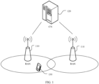
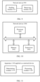
- FIG. 1 is a schematic diagram of an application scenario according to this application.
- a terminal 130 accesses a wireless network, to obtain a service from an external network (for example, the internet) over the wireless network or communicate with another terminal over the wireless network.
- the wireless network includes a RAN 110 and a core network (CN) 120.
- the RAN 110 is used to connect the terminal 130 to the wireless network
- the CN 120 is used to manage the terminal and provide a gateway for communicating with the external network.
- a plurality of activated uplink (uplink, UL) BWPs are supported on one uplink carrier.
- an uplink BWP whose physical uplink control channel (physical uplink control channel, PUCCH) resource is used to transmit a hybrid automatic repeat request (hybrid automatic retransmission request, HARQ) feedback corresponding to PDSCH transmission cannot be determined.
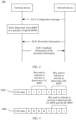
- FIG. 2 is a schematic flowchart of a communication method 200 according to an embodiment of this application.
- the terminal device in FIG. 2 may be the terminal 130 in FIG. 1
- a network device may be the RAN 110 in FIG. 1 .
- the method 200 includes the following steps.
- the network device sends a configuration message to the terminal device, where the configuration message is used to configure a plurality of uplink BWPs and a plurality of downlink BWPs.
- the terminal device receives the configuration message from the network device.
- the configuration message may include other information configured by the network device for the terminal device, for example, an index corresponding to each uplink BWP or downlink BWP, information of a carrier on which each uplink BWP or downlink BWP is located, or information of a cell to which a carrier, on which each uplink BWP or downlink BWP is located, belongs. This is not limited.
- the terminal device may obtain the plurality of uplink BWPs and the plurality of downlink BWPs based on the configuration message.
- content included in the configuration message may be determined based on an actual application scenario.
- the configuration message may be radio resource control (radio resource control, RRC) signaling.
- RRC radio resource control
- the terminal device determines a first BWP in the plurality of uplink BWPs, where the first BWP is used to transmit feedback information of downlink information that is on a second BWP, and the second BWP is any one of the plurality of downlink BWPs.
- the terminal device may determine the first BWP in the plurality of uplink BWPs based on the configuration message. If all the plurality of uplink BWPs are in an active state, the terminal device may select, based on indication information and/or the configuration message, one BWP to transmit the feedback information of the downlink information that is on the second BWP.
- the indication information may be downlink control information (downlink control information, DCI).
- a cell to which the first BWP belongs may be a primary cell PCell, where the first BWP is a BWP belongs to the primary cell.
- the cell to which the first BWP belongs may alternatively be a secondary cell SCell, where the first BWP is a BWP belongs to the secondary cell SCell.
- the network device sends the downlink information to the terminal device by using the second BWP.
- the terminal device receives the downlink information on the second BWP.
- the terminal device may perform decoding processing on the received data.
- the terminal device needs to feed back a decoding result of the data or a transport block (transport block, TB) (to be specific, whether decoding succeeds or fails) to the network device.
- transport block transport block, TB
- S240 The terminal device sends the feedback information of the downlink information by using the first BWP.
- the feedback information may be a hybrid automatic repeat request (HARQ) feedback.
- HARQ hybrid automatic repeat request
- the terminal device transmits the HARQ feedback to the network device by using the first BWP.
- the first BWP when the terminal device transmits the HARQ feedback by using the first BWP, the first BWP needs to be in the active state.
- the first BWP may be ensured to be in the active state in a plurality of manners.
- the method 200 further includes: activating, by the terminal device, the first BWP.
- the terminal device when the terminal device determines that the HARQ feedback needs to be performed on the first BWP, if the first BWP is not activated, the terminal device may activate the first BWP, or if the first BWP is in the active state, the terminal device may directly transmit the HARQ feedback by using the first BWP.
- the terminal device may also activate the first BWP based on an indication of the network device.
- the network device sends an activation indication to the terminal device, where the activation indication is used to indicate to activate the first BWP.
- the terminal device receives the activation indication, and activates the first BWP based on the activation indication.
- the activation indication may be carried in the DCI or a medium access control control element (medium access control control element, MAC CE). This is not limited.
- the terminal device receives the configuration message sent by the network device, where the configuration message is used to configure the plurality of uplink BWPs and the plurality of downlink BWPs; and then determines the first BWP in the plurality of uplink BWPs, where the first BWP is used to transmit the feedback information of the downlink information that is on the second BWP, and the second BWP is any one of the plurality of downlink BWPs; and transmits the HARQ feedback by using the first BWP.
- the terminal device can know a BWP on which the HARQ feedback is performed.
- the following describes in detail, with reference to an indication manner and/or a representation form of the first BWP (including one or more of information (identification information such as an index and an ID) about the first BWP, the carrier on which the first BWP is located, the cell to which the carrier, on which the first BWP is located, belongs, and a correspondence between the first BWP and the second BWP), various implementations of determining the first BWP by the terminal device.
- information such as an index and an ID
- the method 200 further includes: receiving, by the terminal device, the indication information from the network device, where the indication information is used to indicate the first BWP.
- S220 includes: determining, by the terminal device, the first BWP based on the indication information.
- the indication information may be carried in the downlink control information (DCI).
- DCI downlink control information
- the indication information may indicate information having an identification function, such as a BWP number, a BWP ID, or a BWP index of the first BWP. This is not specifically limited.
- the indication information may include only information about the first BWP.
- the indication information does not need to carry information about the cell to which the first BWP belongs and information about the uplink carrier on which the first BWP is located.
- the indication information may further include cell information.
- the indication information may further carry the cell information, and the cell information is used to indicate a cell to which the carrier belongs.
- the purpose of introducing the cell information herein is to determine the cell to which the uplink carrier, on which the first BWP is located, belongs. Because the network device may configure a plurality of secondary cells SCells for the terminal device, the cell, to which the carrier on which the first BWP is located, belongs needs to be determined.
- the cell information may further be carried in the configuration message.
- the network device when configuring the plurality of uplink BWPs and the plurality of downlink BWPs for the terminal device, the network device may notify the terminal device of the cell to which the carrier, on which the first BWP is located, belongs.
- the indication information may further include the information about the uplink carrier on which the first BWP is located.
- the network device configures only the PCell for the terminal device, the PCell is configured with a plurality of uplink carriers, for example, the uplink supplementary uplink (SUL) carrier and a non-SUL carrier, and PUCCH resources are configured for BWPs on the two uplink carriers.
- the indication information does not need to carry the information about the cell to which the first BWP belongs, but needs to carry the information about the uplink carrier on which the first BWP is located.
- the SUL carrier means that the network device uses a 3.5 GHz uplink carrier and a 3.5 GHz downlink carrier in a configured cell.
- a 1.8 GHz supplementary carrier that is, the SUL carrier
- the uplink coverage is ensured by using the introduced low-frequency carrier.
- one downlink carrier and two uplink carriers are configured for one cell of the terminal device, and the two uplink carriers are respectively the SUL carrier and the non-SUL carrier.
- an uplink carrier on which the first BWP is located further needs to be determined.
- the indication information may further carry a carrier index, and the carrier index is used to indicate the uplink carrier on which the first BWP is located.
- the carrier index may be information having a function of identifying a carrier, such as an ID, an index, or a number of the uplink carrier.
- the indication information may carry the following information combinations: information about the first BWP and the cell information, information about the first BWP and the carrier index, or information about the first BWP, the cell information, and the carrier index.
- the information about the first BWP needs to exist, and whether the cell information and the carrier index are required may be determined based on an actual scenario.
- the carrier index may also be carried in the configuration message.
- the network device when configuring the plurality of uplink BWPs and the plurality of downlink BWPs for the terminal device, the network device may notify the terminal device of the carrier on which the first BWP is located.
- the following uses an example in which the DCI carries the cell information and the information about the BWP for detailed description.
- the network device adds an uplink cell index (ulCellIndex) field and an uplink bandwidth part index (ulBwpIndex) field to the DCI used for downlink scheduling.
- the ulCellIndex field is used to indicate that a HARQ feedback corresponding to the PDSCH transmission in the scheduling is fed back on a Cell indicated by the ulCellIndex field.
- the ulBwpIndex field is used to indicate a UL BWP (for example, the first BWP) that is of the indicated Cell and on which the HARQ feedback corresponding to the PDSCH transmission is fed back.
- the terminal device may determine, based on the ulCellIndex field and the ulBwpIndex field in the DCI, a cell to which a BWP belongs and the BWP on which the HARQ feedback corresponding to the PDSCH transmission is transmitted.
- a ulBWP a, a ulBWP b, a ulBWP c, and a ulBWP d are configured on a PUCCH SCell x (x is a cell number)
- the terminal device may determine that the HARQ feedback corresponding to the PDSCH transmission needs to be transmitted on the UL BWP c of the PUCCH SCell x.
- Letters a, b, c, and d are index numbers of BWPs.
- an uplink carrier index ulCarrierIndex field may be added to the DCI, and the ulCarrierIndex field is used to indicate a carrier on which a BWP used to transmit the HARQ feedback corresponding to the PDSCH transmission is located.
- the network device may carry a bitmap (bitmap) indication in the DCI or the MAC CE, and the bitmap indication is used to activate or deactivate an uplink BWP or a downlink BWP.
- the bitmap used to activate or deactivate the uplink BWP and the bitmap used to activate or deactivate the downlink BWP may be carried in one DCI or in one MAC CE.
- the BWP activation command may be included in the DCI or the MAC CE. This is not specifically limited.
- the BWP activation command carries a cell index (cell index) field and a bitmap (bitmap) field, where a cell index indicates a specified cell on which the bitmap field is used to activate/deactivate a BWP.
- a length of one bitmap is the same as a maximum quantity of UL/DL BWPs that can be configured for one cell.
- Bits from right to left in the bitmap separately indicate to activate/deactivate a BWP in ascending order of BWP indexes (for example, if a bit is 1, it indicates to activate a corresponding BWP, and if the bit is 0, it indicates to deactivate a corresponding BWP).
- the BWP activation command may carry two bitmaps: a bitmap used to indicate to activate or deactivate UL BWPs and a bitmap used to indicate to activate or deactivate DL BWPs. If a network device can configure a maximum of four UL BWPs, and only three UL BWPs are configured for the cell indicated by the cell index, three least significant bits (which are respectively 1, 0, and 1) of a corresponding bitmap are used to indicate to activate or deactivate the UL BWP, and the remaining bit does not indicate any meaning. Optionally, three least significant bits (which are respectively 0, 0, and 1) of the bitmap are respectively used to indicate to activate or deactivate the UL BWPs.
- the BWP activation command carries only one bitmap.
- the three least significant bits (which are respectively 1, 0, and 1) of the corresponding bitmap are respectively used to indicate to activate or deactivate the UL BWPs and the DL BWPs.
- a DL BWP activated by a terminal device by using the BWP activation command is a non-default (default) DL BWP
- the terminal device may start a timer corresponding to the activated DL BWP, for example, a BWP inactivity timer.
- a BWP inactivity timer corresponding to one DL BWP times out if a default DL BWP is not activated, the terminal device activates the default DL BWP and deactivates the DL BWP. If the default DL BWP is activated, the terminal device only needs to activate the DL BWP.
- the network device may explicitly indicate a first BWP in DCI, so that the terminal device can transmit a HARQ feedback on the first BWP.
- the configuration message includes a correspondence between the first BWP and the second BWP
- S220 includes: determining, by the terminal device, the first BWP based on the correspondence.
- the terminal device may know, based on the correspondence carried in the configuration message, that feedback information of the downlink information on the second BWP needs to be fed back on the first BWP, so that the first BWP is obtained in a plurality of uplink BWPs.
- the configuration message may be RRC signaling, that is, the RRC signaling includes the correspondence.
- the terminal device may know, via the RRC signaling, that the feedback information of the downlink information on the second BWP needs to be sent by using the first BWP.
- the configuration message may further carry a carrier index, and the carrier index is used to indicate a carrier on which the first BWP is located.
- the configuration message may further carry cell information, and the cell information is used to indicate a cell to which the carrier, on which the first BWP is located, belongs to.
- the configuration message is RRC signaling.
- the network device configures, by using RRC dedicated signaling, a HARQ feedback corresponding to PDSCH transmission on the SCell to be transmitted on a specified BWP (for example, the first BWP) belonging to a specified cell (for example, the cell to which the first BWP belongs).
- a specified BWP for example, the first BWP
- a specified cell for example, the cell to which the first BWP belongs.
- the cellIndex field and a bwpIndex field may be added to the RRC signaling.
- the network device may specifically indicate, in the RRC dedicated signaling by using the cellIndex field, a Cell on which the HARQ feedback corresponding to the PDSCH transmission on the SCell is transmitted, and indicate, by using the bwpIndex field, that the HARQ feedback is transmitted on a specified UL BWP belonging to the determined cell.
- An uplink carrier index (ulCarrierIndex) field is added to the RRC signaling, and the ulCarrierIndex field is used to indicate a carrier on which the BWP used to transmit the HARQ feedback corresponding to the PDSCH transmission is located.
- the network device configures, by using the RRC dedicated signaling, the HARQ feedback corresponding to the PDSCH transmission on the DL BWP to be transmitted on one UL BWP of a specified Cell, for example, the first BWP.
- the network device sends the RRC signaling to the terminal device, and the RRC signaling indicates that the HARQ feedback corresponding to the PDSCH transmission on a DL BWP 1 of an SCell 1 needs to be fed back on a UL BWP c of a PUCCH SCell x, where x represents a cell number, and c represents a BWP number.
- the terminal device After receiving the RRC signaling, the terminal device sends, on the UL BWP c of the PUCCH SCell x, the HARQ feedback corresponding to the PDSCH transmission.
- the UL BWP when the terminal device needs to perform the HARQ feedback on the UL BWP, the UL BWP also needs to be in an active state.
- any one of the following manners may be used:
- the network device may indicate, in the RRC signaling, the first BWP in the first cell, so that the terminal device can transmit the HARQ feedback on the first BWP.
- the terminal device determines the first BWP by combining the configuration message and indication information.
- the configuration message may include the carrier index, and the carrier index is used to indicate the uplink carrier on which the first BWP is located.
- the configuration message may include the cell information, and the cell information is used to indicate the cell to which the uplink carrier, on which the first BWP is located, belongs.
- the configuration message is the RRC signaling
- the indication information is the DCI.
- the DCI may be used to indicate the first BWP.
- the RRC signaling may include the carrier index, and the carrier index is used to indicate an uplink carrier on which the first BWP is located.
- the RRC signaling may further include the cell information, and the cell information is used to indicate the cell to which the uplink carrier, on which the first BWP is located, belongs.
- the terminal device may determine the first BWP based on content of the DCI and content of the RRC signaling.
- the network device may add the cellIndex field to the RRC signaling, where the cellIndex field is used to indicate a specified Cell (for example, a PCell or a PUCCH SCell) on which the HARQ feedback corresponding to the PDSCH transmission on one SCell is transmitted.
- the cellIndex field in the RRC signaling is used to specifically indicate a cell on which the HARQ feedback corresponding to the PDSCH transmission on the SCell is transmitted.
- the cellIndex may be a cell index allocated by the network device for the terminal device when the network device configures a cell for the terminal device.
- the uplink carrier index (ulCarrierIndex) field is added to the RRC signaling or the DCI, and the ulCarrierIndex field is used to indicate a carrier on which the BWP used to transmit the HARQ feedback corresponding to the PDSCH transmission is located.
- an allocated cellIndex is x.
- the network device may add information about an SCell x to the RRC signaling, to indicate the terminal device to transmit, on a PUCCH resource of the SCell x, the HARQ feedback corresponding to the PDSCH transmission on the SCell y.
- the cellIndex may be an index value obtained after the PCell and all the PUCCH SCells are sorted in ascending/descending order of cell indexes. This is not specifically limited. For example, if the cellIndex is an index value obtained after the PCell and the PUCCH SCells are sorted in ascending order of cell indexes, and the network device configures the SCell x, the SCell y, and an SCell z as the PUCCH SCells (x ⁇ y ⁇ z), the cellIndex being 0 indicates the PCell, the cellIndex being 1 indicates the SCell x, the cellIndex being 2 indicates the SCell y, and the cellIndex being 3 indicates the SCell z.
- the terminal device may learn of the information about the cell in which the HARQ feedback is transmitted. Further, the terminal device further needs to learn of a BWP that is of the cell and on which the HARQ feedback is transmitted. Herein, the terminal device may learn of information about the BWP via the DCI sent by the network device.
- the network device adds a ulBwpIndex field to the DCI used for downlink scheduling, where the ulBwpIndex field is used to indicate a UL BWP (for example, the first BWP) that is of the Cell (the Cell indicated in the RRC signaling) and on which the HARQ feedback corresponding to the PDSCH transmission in the scheduling is fed back.
- the terminal device may identify, based on the content (for example, a carrier indicator field (carrier indicator field, CIF) and a BWP Index) of the DCI, a specific BWP on which the HARQ feedback is transmitted.
- the terminal device may learn that the HARQ feedback corresponding to the PDSCH transmission needs to be transmitted on the UL BWP c of the PUCCH SCell x.
- the terminal device further needs to determine uplink carrier information when determining a location of the HARQ feedback corresponding to the PDSCH transmission.
- the uplink carrier information may be carried in the RRC signaling, or the uplink carrier information may be carried in the DCI.
- the UL BWP when the terminal device needs to perform the HARQ feedback on the UL BWP, the UL BWP also needs to be in the active state. Specifically, any one of the following manners may be used:
- the network device may include the cell information in the RRC signaling, and indicate the information about the first BWP in the DCI.
- signaling overheads are lower, so that the terminal device may determine the first BWP with reference to the RRC signaling and the DCI, and further transmit the HARQ feedback on the first BWP.
- S220 includes: determining, by the terminal device, the first BWP based on the correspondence between the first BWP and the second BWP, where the correspondence is preset in the terminal device.
- the foregoing correspondence may also be expressed in another manner, for example, a first preset rule, where the first preset rule is used to indicate that the HARQ feedback of the downlink information on the second BWP of a second cell is transmitte on the first BWP of the first cell.
- the first preset rule is predefined in a protocol.
- the first cell may be understood as a cell to which the first BWP belongs, and the second cell may be understood as a cell to which the second BWP belongs.
- the information about the first BWP may be determined in a manner of predefining in a protocol.
- the configuration message may be RRC signaling.
- the terminal device obtains the information about the first BWP with reference to the rule (or the correspondence) predefined in the protocol, so as to perform the HARQ feedback on the first BWP of the first cell.
- DL BWPs configured on the Cell x are sorted in ascending order of BWP indexes
- UL BWPs that are configured with PUCCH resources and that are on the Cell y are sorted in ascending order of BWP indexes.
- a UL BWP that is of the Cell y and on which the HARQ feedback corresponding to the PDSCH transmission on each DL BWP of the Cell x is transmitted may be determined in a polling manner.
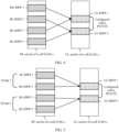
- a preset rule in FIG. 4 is used as an example not covered by the claims.
- the HARQ feedback corresponding to the PDSCH transmission on the Cell x is transmitted on an uplink carrier of the Cell y, a DL BWP 1, a DL BWP 2, a DL BWP 3, and a DL BWP 4 are configured on the Cell x, and a UL BWP 1 and a UL BWP 2 that are configured with PUCCH resources are configured on the Cell y.
- the first preset rule is defined in the polling manner as follows: HARQ feedbacks corresponding to the PDSCH transmission on the DL BWP 1 and the DL BWP 3 are transmitted on the UL BWP 1, and HARQ feedbacks corresponding to the PDSCH transmission on the DL BWP 2 and the DL BWP 4 are transmitted on the UL BWP 2.
- this case is not shown in FIG.
- the DL BWP 1, the DL BWP 2, the DL BWP 3, and the DL BWP 4 are configured on the Cell x
- the UL BWP 1, the UL BWP 2, the UL BWP 3, and the UL BWP 4 that are configured with PUCCH resources are configured on the Cell y
- the HARQ feedback corresponding to the PDSCH transmission on the DL BWP 1 is transmitted on the UL BWP 1
- the HARQ feedback corresponding to the PDSCH transmission on the DL BWP 2 is transmitted on the UL BWP 2
- the HARQ feedback corresponding to the PDSCH transmission on the DL BWP 3 is transmitted on the UL BWP 3
- the HARQ feedback corresponding to the PDSCH transmission on the DL BWP 4 is transmitted on the UL BWP 4.
- DL BWPs configured on the Cell x are sorted in ascending order of BWP indexes
- UL BWPs that are configured with PUCCH resources and that are on the Cell y are sorted in ascending order of BWP indexes.
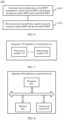
- DL BWPs on the Cell x are grouped. Each group includes ⁇ m/n ⁇ DL BWPs, where m is a quantity of DL BWPs configured on the Cell x, and n is a quantity of UL BWPs that are configured with PUCCHs and that are on the Cell y.
- a UL BWP that is of the Cell y and on which the HARQ feedback corresponding to the PDSCH transmission on each group ofDL BWPs of the Cell x is transmitted may be determined in a grouping manner.
- a preset rule in FIG. 5 is used as an example.
- the DL BWP 1, the DL BWP 2, the DL BWP 3, and the DL BWP 4 are configured on the Cell x, and the UL BWP 1 and the UL BWP 2 that are configured with PUCCH resources are configured on the Cell y.
- the first preset rule is defined in a grouping polling manner as follows: HARQ feedbacks corresponding to the PDSCH transmission on the DL BWP 1 and the DL BWP 2 are transmitted on the UL BWP 1, and HARQ feedbacks corresponding to the PDSCH transmission on the DL BWP 3 and the DL BWP 4 are transmitted on the UL BWP 2.
- the DL BWPs may be divided into two groups, and HARQ feedbacks corresponding to the PDSCH transmission on the two groups of DL BWPs are respectively transmitted on the UL BWP 1 and the UL BWP 2 in the polling manner.
- the RRC signaling may also include the carrier index.
- the UL BWP when the terminal device needs to perform the HARQ feedback on a UL BWP, the UL BWP also needs to be in the active state.
- the terminal device needs to perform the HARQ feedback on a UL BWP
- the UL BWP also needs to be in the active state.
- for a manner of activating the UL BWP refer to the foregoing second optional implementation. For brevity, details are not described herein again.
- the first preset rule may be used to determine a configured or activated UL BWP on which a HARQ feedback of downlink information on a DL BWP configured or activated on a cell is transmitted.
- a UL BWP that is used for a HARQ feedback of downlink information on another DL BWP may change (for example, a deactivated UL BWP may be used for HARQ feedback of downlink information on another DL BWP).
- a new UL BWP may be immediately used to perform the HARQ feedback of downlink information on the another DL BWP, or a new UL BWP may be used to perform the HARQ feedback after a period of time defined in the protocol, so as to ensure that the HARQ feedback of downlink information on the another DL BWP is not affected.
- the network device may carry the information about the cell to which the first BWP belongs in the RRC signaling, so that the terminal device may determine the first BWP with reference to the RRC signaling and the rule predefined in the protocol, and further transmit the HARQ feedback on the first BWP with minimum signaling overheads.
- the terminal device may obtain, based on the indication information, information used to indicate the first BWP.
- the terminal device may obtain, based on the indication information, the information used to indicate the cell to which the first BWP belongs.
- a corresponding HARQ process number may be configured for each BWP in this embodiment of this application, so that resources used on the BWPs to perform the HARQ feedback are independent of each other.
- a semi-persistent scheduling (SPS) configuration is supported for downlink.
- the SPS is configured per serving cell per BWP (per serving cell per BWP), to be specific, there is a maximum of one SPS configuration on a BWP. At most one SPS can be activated and used on a Cell.
- CURRENT_slot [(SFN ⁇ numberOfSlotsPerFrame)+slot number in the frame], where the slot number in the frame indicates a number of a slot in which a resource is located in a radio frame. For example, a number of a first slot in a frame is 0.
- the nrofHARQ-Process indicates a quantity of available processes configured by using RRC for the SPS. Modulo is a modulo operation.
- the semiPersistSchedIntervalDL is a resource periodicity configured by RRC for the SPS. It can be learned that HARQ process IDs available for the SPS resources are 0, 1, ..., and nrofHARQ-Process-1. It should be understood that for a specific meaning involved in the formula, refer to descriptions in the prior art.
- a configured grant (Configured grant) is introduced in the NR.
- the Configured grant is classified into two types: type 1 and type 2.
- type 1 a periodical uplink resource is providedby using RRC signaling and can be used after being configured by using RRC signaling.
- type 2 parameters such as a period and a quantity of available processes are configured by using RRC signaling, and the configured grant is activated by using a PDCCH command.
- An uplink resource is provided by the PDCCH command.
- the terminal device may periodically use the uplink resource based on the period parameter configured by using RRC signaling.
- the Configured grant is configured per cell per BWP (per serving cell per BWP).
- a HARQ process ID associated with the Configured grant resource is calculated by using the following formula:
- the method 200 further includes:
- the configuration message may carry the HARQ process parameter (for example, a startProcessID parameter).
- the configuration message may be RRC dedicated signaling.
- the network device may carry the startProcessID parameter in the RRC dedicated signaling.
- the terminal device may obtain the HARQ process number according to the startProcessID parameter and the nrofHARQ-Processes parameter. For example, available HARQ process numbers of the set of SPS/Configured grant resources are [startProcessID, startProcessID+nrofHARQ-Processes-1].
- the terminal device may obtain through calculation, by using the formula for calculating the HARQ process ID in the prior art, a harqProcessID associated with one set of SPS/Configured grant resource.
- an actual HARQ process number for processing the SPS/Configured grant resource is harqProcessID+startProcessID.
- the terminal device processes the resource by using the HARQ process whose HARQ process number is 5.
- the network device configures the DL BWP 1 and the DL BWP 2 on the Cell x, and one set of SPS resource is configured on each of the two DL BWPs. If in the SPS configuration parameter on the DL BWP 1, the startProcessID is 0, the nrofHARQ-Processes parameter is 2; in the SPS configuration parameter on the DL BWP 2, the startProcessID is 2, and the nrofHARQ-Processes parameter is 2, it can be learned according to the formula [startProcessID, startProcessID+nrofHARQ-Processes-1] that:
- HARQ process numbers available for the SPS on the DL BWP 1 are process 0 and process 1
- HARQ process numbers available for the SPS on the DL BWP 2 are process 2 and process 3. In this way, processes of different SPS configurations are not shared, thereby avoiding a problem that HARQ processes affect each other.
- a HARQ parameter is carried in RRC signaling, and a HARQ process number is determined based on the HARQ parameter, to distinguish between HARQ processes, so that mutual impact between pre-configured resources during usage is avoided, and implementation complexity of the terminal device is low.
- the method 200 further includes: determining, by the terminal device based on a predefined process parameter, the HARQ process number corresponding to the feedback information.
- the predefined process parameter may be a startProcessID parameter.
- the predefined process parameter may be stored in the terminal device.
- the foregoing predefined process parameter may be obtained according to a second preset rule defined in a protocol.
- the terminal device may determine, according to the second preset rule, the HARQ process number corresponding to the HARQ feedback, where the second preset rule is used to indicate a HARQ process number used when HARQ transmission is performed on the first BWP.
- the HARQ process number may be determined in a manner predefined in the protocol.
- the second preset rule indicates that the HARQ process number is determined by using the following formula: [startProcessID, startProcessID+nrofHARQ-Processes-1].
- the network device configures the DL BWP 1 and the DL BWP 2 on the Cell x, and one set of SPS resources is configured on each of the DL BWP 1 and the DL BWP 2, the nrofHARQ-Processes parameter in the SPS configuration parameter on the DL BWP 1 is 3, and the nrofHARQ-Processes parameter in the SPS configuration parameter on the DL BWP 2 is 2.
- startProcessIDs corresponding to the SPS configurations on the DL BWP 1 and the DL BWP 2 respectively are 0 and 3 (where the startProcessIDs are obtained through calculation based on nrofHARQ-Processes corresponding to the SPS configured on BWPs), the foregoing formula of the second preset rule is used to calculate the HARQ process number, and it can be learned that HARQ process numbers available for the SPS on the DL BWP 1 are the process 0 and the process 2, and HARQ process numbers available for the SPS on the DL BWP 2 are the process 3 and the process 4. In this way, it is ensured that processes of different SPS configurations are not shared, and a problem that HARQ processes affect each other does not exist.
- the second preset rule may be defined as follows: For an SPS/Configured grant on a BWP x, y is configured, and a corresponding startProcessID is a sum of nrofHARQ-Processes in the SPS/Configured grant configuration on all BWPs that are configured on the carrier and whose indexes are less than x and a sum of nrofHARQ-Processes in all SPS/Configured grant configurations that are configured on the BWP x and whose indexes are less than y.
- x represents a BWP number
- y represents a number of an SPS/Configured grant configured on a BWP.
- the network device configures the DL BWP 1 and the DL BWP 2 on the Cell x, configures the SPS 1 and the SPS 2 on the DL BWP 1, and configures SPS 1 and SPS 2 (here, the SPS 1 indicates that the index (index) of the SPS is 1, and the SPS 2 indicates that the index of the SPS is 2.
- the SPS indexes on different BWPs may be the same, and may correspond to different SPS configuration parameters) on the DL BWP 2. If the nrofHARQ-Processes parameter of each set of SPS configuration is 2, a startProcessID corresponding to the SPS 2 on the DL BWP 2 is 6, and available processes are HARQ process 6 and HARQ process 7.
- a calculation process of the startProcessID corresponding to the SPS 2 on the DL BWP 2 is as follows:
- the SPS 1 and the SPS 2 are configured on the DL BWP 1, and nrofHARQ-Processes parameters of two sets of SPS configuration are both 2.
- the startProcessID of the SPS 1 on the DL BWP 1 is 0, and available HARQ process IDs are 0 and 1; and the startProcessID of the SPS 2 on the DL BWP 2 is 2, and available HARQ process IDs are 2 and 3.
- the SPS 1 and the SPS 2 are also configured on the DL BWP 2, and the nrofHARQ-Processes parameters of the two sets of SPS configuration are both 2.
- the startProcessID of the SPS 1 on the DL BWP 2 is a sum, that is, 4, of nrofHARQ-Processes corresponding to all SPS configured on all DL BWPs (only the DL BWP 1 in the example) whose indexes are less than 2; and the startProcessID of the SPS 2 on the DL BWP 2 is a sum of nrofHARQ-Processes corresponding to all SPS configured on the DL BWP1 and a sum of nrofHARQ-Processes corresponding to all SPS (only the SPS 1 herein) whose indexes are less than 2 on the DL BWP 2, that is, 6.
- the method in the foregoing case 2 may be used to determine a HARQ process number in the manner predefined in the protocol, to distinguish between HARQ processes, thereby avoiding mutual impact between the pre-configured resources during usage.
- load of RRC signaling in case 2 is relatively small.
- FIG. 3 to FIG. 5 are provided merely to help a person skilled in the art understand the embodiments of this application, instead of limiting the embodiments of this application to specific scenarios shown in the examples.
- a person skilled in the art can make various equivalent modifications or changes based on the examples shown in FIG. 3 to FIG. 5 , and such modifications or changes also fall within the scope of the embodiments of this application.
- an embodiment of this application further provides another communication method.
- FIG. 6 is a schematic flowchart of a communication method 600 of this application that is not covered by the claims. As shown in FIG. 6 , the method 600 includes the following steps.
- a terminal device determines a first BWP combination, where the first BWP combination includes an uplink BWP and a downlink BWP.
- S620 The terminal device performs random access by using the uplink BWP and the downlink BWP.
- the terminal device sends uplink information, for example, a random access preamble and a message Msg3 (there is no message 3 in non-contention-based random access), on the uplink BWP in the first BWP combination, and downlink information, for example, a message 2 and a message 4 (there is no message 4 in the non-contention-based random access mode), is sent on the downlink BWP in the first BWP combination.
- uplink information for example, a random access preamble and a message Msg3 (there is no message 3 in non-contention-based random access)
- Msg3 a message 3 in non-contention-based random access
- the terminal device may select, from activated BWPs, an appropriate uplink BWP and downlink BWP to perform random access.
- the terminal device may select the uplink BWP and the downlink BWP to initiate the random access.
- the terminal device determines the first BWP combination in a plurality of manners. For example, the terminal device may first determine whether there is an activated uplink BWP. If an uplink BWP is activated, the terminal device continues to determine whether a downlink BWP associated with the uplink BWP is activated. If the downlink BWP associated with the uplink BWP is also in an active state, the terminal device may select the BWP combination that includes the uplink BWP and the downlink BWP to perform random access.
- the terminal device may select the first BWP combination based on an index of a BWP, where an index corresponding to the first BWP combination is the largest or the smallest in the plurality of BWP combinations.
- the index of the BWP may be an index of an uplink BWP or an index of a downlink BWP.
- the terminal device may randomly select, from the plurality of BWP combinations, one BWP combination to perform random access.
- the terminal device first selects uplink BWPs and downlink BWPs that have association relationships, and then selects, from the uplink BWPs and the downlink BWPs, a combination in which both an uplink BWP and a downlink BWP are activated as the first BWP combination.
- the terminal device may first determine whether there is an activated downlink BWP. If a downlink BWP is activated, the terminal device continues to determine whether an uplink BWP associated with the downlink BWP is activated. If the uplink BWP associated with the downlink BWP is also in the active state, the terminal device may select the BWP combination that includes the uplink BWP and the downlink BWP to perform random access.
- the terminal device may further select the first BWP combination based on a degree of density of access resource configuration on each BWP combination.
- the access resource refers to a physical random access channel (Physical Random Access Channel, PRACH) resource.
- PRACH Physical Random Access Channel
- the degree of the density of the access resource configuration may be a quantity of PRACH occasions configured in one radio frame, or may be a quantity of PRACH occasions configured in another specified period of time. This is not specifically limited.
- the foregoing other manners of determining the first BWP combination may be used.
- the manners may be used in combination. This is not specifically limited.
- the terminal device selects the first BWP combination to perform random access.
- the terminal device may select a BWP combination in the foregoing manner (random selection or selection based on an index).
- the method 600 further includes:
- the terminal device may determine whether there is an uplink BWP configured with an access resource. If the terminal device determines that a first uplink BWP is in the active state and is configured with the access resource, the terminal device may select the first uplink BWP. In addition, the terminal device activates a first downlink BWP corresponding to the first uplink BWP, to obtain an appropriate BWP combination with this pair of the first uplink BWP and the first downlink BWP, that is, the first BWP combination, and then initiates random access by using the first BWP combination.
- the method 600 further includes:
- the terminal device may randomly select one uplink BWP as the uplink BWP (for example, the first uplink BWP) of the first BWP combination, or may select the uplink BWP in the first BWP combination based on a BWP index. This is not limited.
- That a terminal device determines a first BWP combination includes: selecting, by the terminal device, the first BWP combination based on a degree of density of access resource configuration on each of a plurality of BWP combinations.
- the terminal device may alternatively select to activate an initial (initial) UL/DL BWP to initiate the RACH.
- the terminal device selects an appropriate UL/DL BWP to initiate random access.
- sequence numbers of the foregoing processes do not mean execution sequences in various embodiments of this application.
- the execution sequences of the processes should be determined based on functions and internal logic of the processes, and should not be construed as any limitation on the implementation processes of the embodiments of this application.
- An embodiment of this application further provides an apparatus for implementing any one of the foregoing methods.
- the apparatus includes units (or means) configured to implement steps performed by the terminal in any one of the foregoing methods.
- another apparatus is further provided, including units (or means) configured to implement the steps performed by the network device in any one of the foregoing methods.
- FIG. 7 is a schematic block diagram of an apparatus 700 applied to a terminal device
- the terminal device may include the apparatus 700.
- the apparatus 700 includes:
- the transceiver module 710 is further configured to:
- the indication information further includes a carrier index, and the carrier index is used to indicate a carrier on which the first BWP is located.
- the indication information further includes cell information, and the cell information is used to indicate a cell to which the carrier belongs.
- the configuration message includes a correspondence between the first BWP and the second BWP, and the determining module 720 is configured to determine the first BWP based on the correspondence.
- the determining module 720 is configured to determine the first BWP based on the correspondence between the first BWP and the second BWP, where the correspondence is preset in the apparatus.
- the configuration message includes the carrier index, and the carrier index is used to indicate the carrier on which the first BWP is located.
- the configuration message further includes the cell information, and the cell information is used to indicate the cell to which the carrier belongs.
- the apparatus 700 further includes an activating module, configured to activate the first BWP.
- the transceiver module 710 is further configured to receive an activation indication from the network device, where the activation indication is used to indicate to activate the first BWP, and the activating module is configured to activate the first BWP based on the activation indication.
- the transceiver module 710 is further configured to receive a HARQ process parameter from the network device; and the determining module 720 is configured to determine, based on the HARQ process parameter, a HARQ process number corresponding to the feedback information.
- the determining module 720 is configured to determine, based on a predefined process parameter, a HARQ process number corresponding to the feedback information.
- the apparatus 700 may correspond to the method on a terminal device side in the foregoing method embodiments (including FIG. 2 to FIG. 5 ), and the foregoing and other management operations and/or functions of the modules in the apparatus 700 are respectively used to implement corresponding steps of the foregoing methods. Therefore, beneficial effects in the foregoing method embodiments may also be implemented. For brevity, details are not described herein again.
- FIG. 8 is a schematic structural diagram of an apparatus 800 applied to a terminal device according to an embodiment of this application.
- the terminal device may include the apparatus 800.
- the apparatus 800 includes: a processor 801, a memory 802, and a transceiver circuit 803.
- the processor 801, the memory 802, and the transceiver circuit 803 communicate with each other through an internal connection path, to transfer a control and/or data signal.
- the processor 801, the memory 802, and the transceiver circuit 803 may be implemented by a chip.
- the memory 802 may store program code, and the processor 801 invokes the program code stored in the memory 802, to implement a corresponding function of the terminal device.
- the transceiver circuit 803 is configured to receive a configuration message from a network device, where the configuration message is used to configure a plurality of uplink BWPs and a plurality of downlink BWPs.
- the processor 801 is configured to determine a first BWP in the plurality of uplink BWPs, where the first BWP is used to transmit feedback information of downlink information that is on a second BWP, and the second BWP is any one of the plurality of downlink BWPs.
- the transceiver circuit 803 is further configured to: receive the downlink information on the second BWP, and send the feedback information of the downlink information by using the first BWP.
- the transceiver module 710 in the apparatus 700 shown in FIG. 7 may correspond to the transceiver circuit 803 in the apparatus 800 shown in FIG. 8
- the determining module 720 may correspond to the processor 801 in the apparatus 800 shown in FIG. 8 .
- the transceiver module or the transceiver circuit is an interface circuit of the apparatus, and is configured to receive a signal from another apparatus or send a signal to another apparatus.
- the transceiver module or the transceiver circuit is an interface circuit that is of the chip and that is configured to receive a signal from another chip or apparatus or send a signal to another chip or apparatus.
- the apparatus 700 may be a chip (or a chip system) installed in the terminal device.
- the apparatus 700 may include a processor and an input/output interface.
- the processor may be communicatively connected to a transceiver of the network device through the input/output interface.
- the apparatus further includes a memory, where the memory is communicatively connected to the processor.
- the processor, the memory, and the transceiver circuit may be communicatively connected.
- the memory may be configured to store an instruction.
- the processor is configured to execute the instruction stored in the memory, to control the transceiver circuit to send information or a signal.
- apparatus 800 may correspond to the method on the terminal device side in the foregoing method embodiments.
- FIG. 9 is a schematic block diagram of a network device 900 according to an embodiment of this application. As shown in FIG. 9 , the network device 900 includes:
- the sending module 910 is further configured to: send indication information to the terminal device, where the indication information is used to indicate the first BWP.
- the indication information further includes a carrier index, and the carrier index is used to indicate a carrier on which the first BWP is located.
- the indication information further includes cell information, and the cell information is used to indicate a cell to which the carrier belongs.
- the configuration message includes a correspondence between the first BWP and the second BWP, and the correspondence is used by the terminal device to determine the first BWP.
- the configuration message includes the carrier index, and the carrier index is used to indicate the carrier on which the first BWP is located.
- the configuration message further includes the cell information, and the cell information is used to indicate the cell to which the carrier belongs.
- the sending module 910 is further configured to: send an activation indication to the terminal device, where the activation indication is used to indicate the terminal device to activate the first BWP.
- the sending module 910 is further configured to: send a HARQ process parameter to the terminal device, where the HARQ process parameter is used by the terminal device to determine a HARQ process number corresponding to the feedback information.
- the network device 900 may correspond to the method on the network device side in the foregoing method embodiments (including FIG. 2 to FIG. 5 ), and the foregoing and other management operations and/or functions of the modules in the network device 900 are respectively used to implement corresponding steps of the foregoing methods. Therefore, beneficial effects in the foregoing method embodiments may also be implemented. For brevity, details are not described herein again.
- FIG. 10 is a schematic structural diagram of a network device 1000. As shown in FIG. 10 , the network device 1000 includes: a processor 1001, a memory 1002, and a transceiver 1003.
- the processor 1001, the memory 1002, and the transceiver 1003 communicate with each other through an internal connection path, to transfer a control and/or data signal.
- the processor 1001, the memory 1002, and the transceiver 1003 may be implemented by a chip.
- the memory 1002 may store program code, and the processor 1001 invokes the program code stored in the memory 1002, to implement a corresponding function of the network device.
- the transceiver 1003 is configured to send a configuration message to a terminal device, where the configuration message is used to configure a plurality of uplink BWPs and a plurality of downlink BWPs, and the plurality of uplink BWPs are used by the terminal device to determine a first BWP.
- the transceiver 1003 is further configured to send downlink information to the terminal device by using a second BWP, where the second BWP is any one of the plurality of downlink BWPs; and is further configured to receive feedback information that is of the downlink information and that is sent by the terminal device by using the first BWP.
- the sending module 910 and the receiving module 920 in the network device 900 shown in FIG. 9 may also correspond to the transceiver 1003 in the network device 1000 shown in FIG. 10 .
- the transceiver may be implemented by two components: a receiver (corresponding to the receiving module 920) and a transmitter (corresponding to the sending module 920).
- the network device 900 may be a chip (or a chip system) installed in a network device.
- the network device 900 may include a processor and an input/output interface.
- the processor may be communicatively connected to a transceiver of the network device through the input/output interface.
- the apparatus further includes a memory, where the memory is communicatively connected to the processor.
- the processor, the memory, and the transceiver may be communicatively connected.
- the memory may be configured to store an instruction.
- the processor is configured to execute the instruction stored in the memory, to control the transceiver to send information or a signal.
- network device 1000 may correspond to the method on the network device side in the foregoing method embodiments.
- FIG. 11 is a schematic block diagram of an apparatus 1100 applied to a terminal device.
- the terminal device may include the apparatus 1100.
- the apparatus 1100 includes:
- the uplink BWP and the downlink BWP that are in the first BWP combination are in an active state, and the uplink BWP and the downlink BWP that are in the first BWP combination are configured with an association relationship.
- the processing module 1120 is further configured to:
- the processing module is further configured to:
- the determining module 1110 is configured to: select the first BWP combination based on a degree of density of access resource configuration on each of a plurality of BWP combinations.
- the apparatus 1100 may correspond to the method of the terminal device (for example, FIG. 6 ), and the foregoing and other management operations and/or functions of the modules in the apparatus 1100 are respectively used to implement corresponding steps of the foregoing methods. Therefore, beneficial effects in the foregoing methods may also be implemented. For brevity, details are not described herein again.
- FIG. 12 is a schematic structural diagram of an apparatus 1200 applied to a terminal device.
- the terminal device may include the apparatus 1200.
- the apparatus 1200 includes: a processor 1201, a memory 1202, and a transceiver circuit 1203.
- the processor 1201, the memory 1202, and the transceiver circuit 1203 communicate with each other through an internal connection path, to transfer a control and/or data signal.
- the processor 1201, the memory 1202, and the transceiver circuit 1203 may be implemented by a chip.
- the memory 1202 may store program code, and the processor 1201 invokes the program code stored in the memory 1202, to implement a corresponding function of the terminal device.
- the processor 1201 is configured to determine a first BWP combination, where the first BWP combination includes an uplink BWP and a downlink BWP, and is further configured to perform random access by using the uplink BWP and the downlink BWP.
- the determining module 1110 and the processing module 1120 in the apparatus 1100 shown in FIG. 11 may correspond to the processor 1201 in the apparatus 1200 shown in FIG. 12 .
- the transceiver module or the transceiver circuit is an interface circuit of the apparatus, and is configured to receive a signal from another apparatus or send a signal to another apparatus.
- the transceiver module or the transceiver circuit is an interface circuit that is of the chip and that is configured to receive a signal from another chip or apparatus or send a signal to another chip or apparatus.
- the apparatus 1100 may be a chip (or a chip system) installed in the terminal device.
- the apparatus 1100 may include a processor and an input/output interface.
- the processor may be communicatively connected to a transceiver of the network device through the input/output interface.
- the apparatus further includes a memory, where the memory is communicatively connected to the processor.
- the processor, the memory, and the transceiver circuit may be communicatively connected.
- the memory may be configured to store an instruction.
- the processor is configured to execute the instruction stored in the memory, to control the transceiver circuit to send information or a signal.
- apparatus 1200 may correspond to the method on the terminal device side in the foregoing method embodiments.
- the methods disclosed in this application may be applied to a processor or may be implemented by a processor.
- the processor may be an integrated circuit chip and has a signal processing capability.
- steps in the foregoing methods may be implemented by using a hardware integrated logic circuit in the processor, or by using an instruction in a form of software.
- the processor may be a general purpose processor, a digital signal processor (digital signal processor, DSP), an application-specific integrated circuit (application specific integrated circuit, ASIC), a field programmable gate array (field programmable gate array, FPGA) or another programmable logic device, a discrete gate, a transistor logic device, a discrete hardware component, a system on chip (system on chip, SoC), a central processing unit (central processor unit, CPU), a network processor (network processor, NP), a digital signal processing circuit (digital signal processor, DSP), a micro controller unit (micro controller unit, MCU), a programmable controller (programmable logic device, PLD), or another integrated chip.
- DSP digital signal processor
- ASIC application specific integrated circuit
- FPGA field programmable gate array
- FPGA field programmable gate array
- the general purpose processor may be a microprocessor, or the processor may be any conventional processor or the like.
- the steps of the methods disclosed in this application may be directly executed and accomplished by using a hardware decoding processor, or may be executed and accomplished by using a combination of hardware and software modules in a decoding processor.
- the software module may be located in a mature storage medium in the art, such as a random access memory, a flash memory, a read-only memory, a programmable read-only memory, an electrically erasable programmable memory, or a register.
- the storage medium is located in the memory, and the processor reads information in the memory and completes the steps in the foregoing methods in combination with hardware of the processor.
- the memory may be a volatile memory or a nonvolatile memory, or may include both a volatile memory and a nonvolatile memory.
- the nonvolatile memory may be a read-only memory (read-only memory, ROM), a programmable read-only memory (programmable ROM, PROM), an erasable programmable read-only memory (erasable PROM, EPROM), an electrically erasable programmable read-only memory (electrically EPROM, EEPROM), or a flash memory.
- the volatile memory may be a random access memory (random access memory, RAM), used as an external cache.
- RAMs may be used, for example, a static random access memory (static RAM, SRAM), a dynamic random access memory (dynamic RAM, DRAM), a synchronous dynamic random access memory (synchronous DRAM, SDRAM), a double data rate-synchronous dynamic random access memory (double Data Rate SDRAM, DDR SDRAM), an enhanced synchronous dynamic random access memory (enhanced SDRAM, ESDRAM), a synchlink dynamic random access memory (synchronous link DRAM, SLDRAM), and a direct rambus random access memory (direct rambus RAM, DR RAM).
- static random access memory static random access memory
- DRAM dynamic random access memory
- DRAM dynamic random access memory
- SDRAM synchronous DRAM
- SDRAM double data rate-synchronous dynamic random access memory
- double Data Rate SDRAM double Data Rate SDRAM
- ESDRAM enhanced synchronous dynamic random access memory
- synchlink dynamic random access memory synchronous link DRAM, SLDRAM
- direct rambus RAM direct rambus RAM, DR RAM
- FIG. 13 is a schematic structural diagram of a terminal according to an embodiment of this application.
- the terminal is the terminal device in the foregoing embodiments, and may be configured to implement operations of the terminal device in the foregoing embodiments.
- the terminal includes an antenna 310, a radio frequency part 320, and a signal processing part 330.
- the antenna 310 is connected to the radio frequency part 320.
- the radio frequency part 320 receives, via the antenna 310, information sent by a network device, and sends, to the signal processing part 330, the information sent by the network device for processing.
- the signal processing part 330 processes the information of the terminal, and sends the information of the terminal to the radio frequency part 320.
- the radio frequency part 320 processes the information of the terminal, and then sends the processed information of the terminal to the network device via the antenna 310.
- the signal processing part 330 may include a modem subsystem, configured to process data at each communications protocol layer.
- the signal processing part 330 may further include a central processing subsystem, configured to implement processing of an operating system and an application layer of the terminal.
- the signal processing part 330 may further include another subsystem, for example, a multimedia subsystem or a peripheral subsystem.
- the multimedia subsystem is configured to control a camera or a screen display of the terminal, and the peripheral subsystem is configured to implement a connection to another device.
- the modem subsystem may be a separately disposed chip.
- the foregoing apparatus applied to a terminal may be located in the modem subsystem.
- the modem subsystem may include one or more processing elements 331, for example, include a main control CPU and another integrated circuit.
- the modem subsystem may further include a storage element 332 and an interface circuit 333.
- the storage element 332 is configured to store data and a program.
- the program used to perform the methods performed by the terminal in the foregoing methods may not be stored in the storage element 332, but is stored in a memory outside the modem subsystem, and is loaded and used by the modem subsystem when to be used.
- the interface circuit 333 is configured to communicate with another subsystem.
- the foregoing apparatus used for the terminal may be located in the modem subsystem.
- the modem subsystem may be implemented by using a chip.
- the chip includes at least one processing element and an interface circuit.
- the processing element is configured to perform the steps of any method performed by the terminal.
- the interface circuit is configured to communicate with another apparatus.
- units of the terminal that implement the steps in the foregoing methods may be implemented by a processing element scheduling a program.
- the apparatus used for the terminal includes a processing element and a storage element.
- the processing element invokes a program stored in the storage element, to perform the methods performed by the terminal in the foregoing method embodiments.
- the storage element may be a storage element whose processing element is located on a same chip, that is, an on-chip storage element.
- the program used to perform the methods performed by the terminal in the foregoing methods may be in a storage element located on a different chip from the processing element, that is, an off-chip storage element.
- the processing element invokes or loads the program from the off-chip storage element to the on-chip storage element, to invoke and perform the methods performed by the terminal in the foregoing method embodiments.
- units of the terminal that implement the steps in the foregoing methods may be configured as one or more processing elements.
- the processing elements are disposed in the modem subsystem.
- the processing element herein may be an integrated circuit, for example, one or more ASICs, one or more DSPs, one or more FPGAs, or a combination of the types of integrated circuits.
- the integrated circuits may be integrated together to form a chip.
- Units of the terminal that implement the steps in the foregoing methods may be integrated together, and implemented in a form of a system-on-a-chip (system-on-a-chip, SOC).
- SOC system-on-a-chip
- the SOC chip is configured to implement the foregoing methods.
- At least one processing element and a storage element may be integrated into the chip, and the processing element invokes a program stored in the storage element to implement the foregoing methods performed by the terminal.
- at least one integrated circuit may be integrated into the chip, to implement the foregoing methods performed by the terminal.
- functions of some units are implemented by a processing element invoking a program, and functions of some units are implemented by an integrated circuit.
- the foregoing apparatus used for the terminal may include at least one processing element and an interface circuit.
- the at least one processing element is configured to perform any method performed by the terminal provided in the foregoing method embodiments.
- the processing element may perform all steps performed by the terminal in the foregoing method embodiments, in a first manner, to be specific, by executing the program stored in the storage element; or may perform all steps performed by the terminal in the foregoing method embodiments, in a second manner, to be specific, by using the hardware integrated logical circuit in the processor element in combination with instructions; or may certainly perform, by combining the first manner and the second manner all steps performed by the terminal in the foregoing method embodiments.
- the processing element herein may be a general purpose processor, for example, a CPU, or may be one or more integrated circuits configured to implement the foregoing methods, for example, one or more ASICs, one or more micro processors DSPs, or one or more FPGAs, or a combination of at least two of the integrated circuit forms.
- the storage element may be a memory, or may be a general name of a plurality of storage elements.
- FIG. 14 is a schematic structural diagram of a network device that includes an antenna 201, a radio frequency apparatus 202, and a baseband apparatus 203.
- the antenna 201 is connected to the radio frequency apparatus 202.
- the radio frequency apparatus 202 receives, via the antenna 201, information sent by a terminal, and sends, to the baseband apparatus 203, the information sent by the terminal for processing.
- the baseband apparatus 203 processes information for the terminal, and sends the information for the terminal to the radio frequency apparatus 202.
- the radio frequency apparatus 202 processes the information for the terminal, and then sends the processed information for the terminal to the terminal via the antenna 201.
- the baseband apparatus 203 may include one or more processing elements 2031, for example, include a main control CPU and another integrated circuit.
- the baseband apparatus 203 may further include a storage element 2032 and an interface 2033.
- the storage element 2032 is configured to store a program and data.
- the interface 2033 is configured to exchange information with the radio frequency apparatus 202, and the interface is, for example, a common public radio interface (common public radio interface, CPRI).
- the foregoing apparatus used for the network device may be located in the baseband apparatus 203.
- the foregoing apparatus used for the network device may be a chip in the baseband apparatus 203.
- the chip includes at least one processing element and an interface circuit.
- the processing element is configured to perform the steps of any method performed by the network device.
- the interface circuit is configured to communicate with another apparatus.
- units of the network device that implement the steps in the foregoing methods may be implemented by a processing element scheduling a program.
- the apparatus used for the network device includes a processing element and a storage element.
- the processing element invokes a program stored in the storage element, to perform the methods performed by the network device in the foregoing method embodiments.
- the storage element may be a storage element that is located on a same chip as the processing element, that is, an on-chip storage element, or may be a storage element that is located on a different chip from the processing element, that is, an off-chip storage element.
- units of the network device that implement the steps in the foregoing methods may be configured as one or more processing elements.
- the processing elements are disposed in the baseband apparatus.
- the processing element herein may be an integrated circuit, for example, one or more ASICs, one or more DSPs, one or more FPGAs, or a combination of the types of integrated circuits.
- the integrated circuits may be integrated together to form a chip.
- Units of the network device that implement the steps in the foregoing methods may be integrated together, and implemented in a form of a system-on-a-chip (system-on-a-chip, SOC).
- the baseband apparatus includes the SOC chip, configured to implement the foregoing methods.
- At least one processing element and a storage element may be integrated into the chip, and the processing element invokes a program stored in the storage element to implement the foregoing methods performed by the network device.
- at least one integrated circuit may be integrated into the chip, to implement the foregoing methods performed by the network device.
- functions of some units are implemented by a processing element invoking a program, and functions of some units are implemented by an integrated circuit.
- the foregoing apparatus used for the network device may include at least one processing element and an interface circuit.
- the at least one processing element is configured to perform any method performed by the network device.
- the processing element may perform all steps performed by the network device, in a first manner, to be specific, by executing the program stored in the storage element; or may perform all steps performed by the network device, in a second manner, to be specific, by using the hardware integrated logical circuit in the processor element in combination with instructions; or may certainly perform, by combining the first manner and the second manner, all steps performed by the network device.
- the processing element herein may be a general purpose processor, for example, a CPU, or may be one or more integrated circuits configured to implement the foregoing methods, for example, one or more ASICs, one or more micro processors DSPs, or one or more FPGAs, or a combination of at least two of the integrated circuit forms.
- the storage element may be a memory, or may be a general name of a plurality of storage elements.
- the disclosed system, apparatus, and method may be implemented in other manners.
- the described apparatus embodiment is merely an example.
- division into units is merely logical function division and may be other division in actual implementation.
- a plurality of units or components may be combined or integrated into another system, or some features may be ignored or not performed.
- the displayed or discussed mutual couplings or direct couplings or communication connections may be implemented through some interfaces.
- the indirect couplings or communication connections between the apparatuses or units may be implemented in an electronic form, a mechanical form, or another form.
- the units described as separate parts may or may not be physically separate, and parts displayed as units may or may not be physical units, may be located in one position, or may be distributed on a plurality of network units. Some or all of the units may be selected based on actual requirements to achieve the objectives of the solutions of the embodiments.
- function units in the embodiments of this application may be integrated into one processing unit, or each of the units may exist alone physically, or two or more units are integrated into one unit.
- the functions When the functions are implemented in the form of a software function unit and sold or used as an independent product, the functions may be stored in a computer-readable storage medium. Based on such an understanding, the technical solutions of this application essentially, or the part contributing to the prior art, or some of the technical solutions may be implemented in a form of a software product.
- the computer software product is stored in a storage medium, and includes several instructions for instructing a computer device (which may be a personal computer, a server, or a network device) to perform the steps of the methods described in the embodiments of this application.
- the foregoing storage medium includes: any medium that can store program code, such as a USB flash drive, a removable hard disk, a read-only memory ROM, a random access memory RAM, a magnetic disk, or an optical disc.
Landscapes
- Engineering & Computer Science (AREA)
- Signal Processing (AREA)
- Computer Networks & Wireless Communication (AREA)
- Mobile Radio Communication Systems (AREA)
Claims (11)
- Kommunikationsverfahren (200), umfassend:Empfangen (S210) einer Konfigurationsnachricht von einer Netzwerkvorrichtung (110) durch eine Endgerätevorrichtung (130), wobei die Konfigurationsnachricht dazu geeignet ist, eine Vielzahl von Uplink-Bandbreitenteilen, BWPs, auf einem Uplink-Träger und eine Vielzahl von Downlink-BWPs zu konfigurieren;gekennzeichnet durchEmpfangen von Anzeigeinformationen von der Netzwerkvorrichtung (110) durch die Endgerätevorrichtung (130), wobei die Anzeigeinformationen einen ersten BWP anzeigen; undBestimmen (S220) des ersten Bandbreitenteils, BWP, in der Vielzahl von Uplink-BWPs durch die Endgerätevorrichtung (130) basierend auf den Anzeigeinformationen als BWP zum Übertragen von Feedback-Informationen von Downlink-Informationen, die sich auf einem zweiten BWP unter der Vielzahl von Downlink-BWPs befinden;Empfangen (S230) der Downlink-Informationen auf dem zweiten BWP durch die Endgerätevorrichtung (130); undSenden (S240) der Feedback-Informationen der Downlink-Informationen auf dem ersten BWP durch die Endgerätevorrichtung (130) .
- Verfahren (200) nach Anspruch 1, wobei die Anzeigeinformationen ferner einen Trägerindex umfassen und der Trägerindex den Uplink-Träger als den Träger anzeigt, auf welchem sich der erste BWP befindet.
- Verfahren (200) nach Anspruch 1 oder 2, wobei die Anzeigeinformationen ferner Zellinformationen umfassen und die Zellinformationen eine Zelle anzeigen, zu welcher der Uplink-Träger gehört.
- Kommunikationsverfahren (200), umfassend:Empfangen (S210) einer Konfigurationsnachricht von einer Netzwerkvorrichtung (110) durch eine Endgerätevorrichtung (130), wobei die Konfigurationsnachricht dazu geeignet ist, eine Vielzahl von Uplink-Bandbreitenteilen, BWPs, auf einem Uplink-Träger und eine Vielzahl von Downlink-BWPs zu konfigurieren;gekennzeichnet durchBestimmen (S220) von Downlink-Informationen, die sich auf dem zweiten BWP unter der Vielzahl von Downlink-BWPs befinden, durch die Endgerätevorrichtung (130) basierend auf einer Entsprechung zwischen einem ersten BWP und einem zweiten BWP in der Vielzahl von Uplink-BWPs als BWPs zum Übertragen von Feedback-Informationen, wobei die Entsprechung in der Konfigurationsnachricht übertragen wird;Empfangen (S230) der Downlink-Informationen auf dem zweiten BWP durch die Endgerätevorrichtung (130); undSenden (S240) der Feedback-Informationen der Downlink-Informationen auf dem ersten BWP durch die Endgerätevorrichtung (130) .
- Verfahren (200) nach einem der Ansprüche 1 und 4, wobei die Konfigurationsnachricht einen Trägerindex umfasst und der Trägerindex den Uplink-Träger als den Träger anzeigt, auf welchem sich der erste BWP befindet.
- Verfahren (200) nach Anspruch 2 oder 5, wobei die Konfigurationsnachricht ferner Zellinformationen umfasst und die Zellinformationen eine Zelle anzeigen, zu welcher der Uplink-Träger gehört.
- Verfahren (200) nach einem der Ansprüche 1 bis 6, wobei das Verfahren vor dem Senden (S240) der Feedback-Informationen der Downlink-Informationen auf dem ersten BWP durch die Endgerätevorrichtung (130) ferner Folgendes umfasst:
Aktivieren des ersten BWP durch die Endgerätevorrichtung (130). - Verfahren nach Anspruch 7, wobei das Verfahren ferner Folgendes umfasst:Empfangen einer Aktivierungsanzeige von der Netzwerkvorrichtung (110) durch die Endgerätevorrichtung (130), wobei die Aktivierungsanzeige anzeigt, den ersten BWP zu aktivieren; unddas Aktivieren des ersten BWP durch die Endgerätevorrichtung (130) Folgendes umfasst:
Aktivieren des ersten BWP durch die Endgerätevorrichtung (130) basierend auf der Aktivierungsanzeige. - Verfahren nach einem der Ansprüche 1 bis 8, wobei das Verfahren ferner Folgendes umfasst:Empfangen eines Prozessparameters einer hybriden automatischen Neuübertragungsanforderung, HARQ, von der Netzwerkvorrichtung (110) durch die Endgerätevorrichtung (130); undBestimmen einer HARQ-Prozessnummer entsprechend den Rückmeldungsinformationen durch die Endgerätevorrichtung (130) basierend auf dem HARQ-Prozessparameter.
- Speichermedium, umfassend ein geeignetes Programm, wenn das Programm durch einen Prozessor einer Endgerätevorrichtung ausgeführt wird, um zu bewirken, dass die Endgerätevorrichtung das Verfahren nach einem der Ansprüche 1 bis 9 durchführt.
- Endgerätevorrichtung (700, 800, 1100, 1200), das dazu konfiguriert ist, das Verfahren nach einem der Ansprüche 1 bis 9 durchzuführen.
Applications Claiming Priority (2)
| Application Number | Priority Date | Filing Date | Title |
|---|---|---|---|
| CN201810450812.4A CN110474735B (zh) | 2018-05-11 | 2018-05-11 | 通信方法和通信装置 |
| PCT/CN2019/083745 WO2019214424A1 (zh) | 2018-05-11 | 2019-04-22 | 通信方法和通信装置 |
Publications (3)
| Publication Number | Publication Date |
|---|---|
| EP3787211A1 EP3787211A1 (de) | 2021-03-03 |
| EP3787211A4 EP3787211A4 (de) | 2021-04-14 |
| EP3787211B1 true EP3787211B1 (de) | 2025-01-15 |
Family
ID=68467235
Family Applications (1)
| Application Number | Title | Priority Date | Filing Date |
|---|---|---|---|
| EP19799143.3A Active EP3787211B1 (de) | 2018-05-11 | 2019-04-22 | Kommunikationsverfahren und kommunikationsvorrichtung |
Country Status (4)
| Country | Link |
|---|---|
| US (1) | US11601248B2 (de) |
| EP (1) | EP3787211B1 (de) |
| CN (1) | CN110474735B (de) |
| WO (1) | WO2019214424A1 (de) |
Families Citing this family (13)
| Publication number | Priority date | Publication date | Assignee | Title |
|---|---|---|---|---|
| EP3934150A1 (de) * | 2018-05-15 | 2022-01-05 | Comcast Cable Communications, LLC | Mehrere aktive bandbreitenteile |
| CN110635870B (zh) * | 2018-06-22 | 2021-05-18 | 华为技术有限公司 | 生成混合自动重传请求harq信息的方法和装置 |
| WO2020034303A1 (en) * | 2018-09-20 | 2020-02-20 | Zte Corporation | Methods, apparatus and systems for scheduling resources in a wireless communication |
| CN109496447B (zh) * | 2018-10-19 | 2022-07-15 | 北京小米移动软件有限公司 | 定时器配置方法及装置 |
| US11184140B2 (en) * | 2018-11-01 | 2021-11-23 | Comcast Cable Communications, Llc | Uplink transmissions using multiple active resources |
| KR102770148B1 (ko) * | 2018-12-28 | 2025-02-21 | 삼성전자 주식회사 | 무선 통신 시스템에서 비승인 데이터 전송 방법 및 장치 |
| US11064538B2 (en) * | 2019-01-25 | 2021-07-13 | FG Innovation Company Limited | Methods and apparatuses for performing random access procedures |
| WO2021008174A1 (en) * | 2019-07-12 | 2021-01-21 | Telefonaktiebolaget Lm Ericsson (Publ) | Methods, terminal device and network node for uplink transmission |
| US11277844B2 (en) * | 2019-08-16 | 2022-03-15 | Qualcomm Incorporated | Coordination of semi-persistent scheduling downlink transmissions and dynamic downlink transmissions |
| WO2021159305A1 (zh) * | 2020-02-12 | 2021-08-19 | Oppo广东移动通信有限公司 | 通信方法及装置 |
| CN114980328A (zh) * | 2020-05-14 | 2022-08-30 | Oppo广东移动通信有限公司 | 资源位置的确定方法、装置、设备及存储介质 |
| CN115811387B (zh) * | 2021-09-14 | 2026-04-14 | 中国移动通信有限公司研究院 | 通信方法、装置、通信设备及存储介质 |
| US11968153B2 (en) * | 2021-11-12 | 2024-04-23 | Qualcomm Incorporated | Timing considerations and switching between time division duplexing patterns in flexible bandwidth parts |
Family Cites Families (14)
| Publication number | Priority date | Publication date | Assignee | Title |
|---|---|---|---|---|
| CN102724766B (zh) * | 2006-01-17 | 2016-03-16 | 上海原动力通信科技有限公司 | 宽带时分双工移动通信系统的物理层随机接入方法 |
| US8620334B2 (en) * | 2009-03-13 | 2013-12-31 | Interdigital Patent Holdings, Inc. | Method and apparatus for carrier assignment, configuration and switching for multicarrier wireless communications |
| KR101678686B1 (ko) * | 2009-05-14 | 2016-11-24 | 엘지전자 주식회사 | 무선 통신 시스템에서 cqi 전송 방법 및 장치 |
| EP3541005A1 (de) * | 2012-03-23 | 2019-09-18 | HFI Innovation Inc. | Verfahren zur konfiguration einer mehrpunkt-trägeraggregation und datenweiterleitung |
| CN103986566B (zh) * | 2014-05-29 | 2017-11-24 | 上海华为技术有限公司 | 一种上行数据的发送方法、基站、用户设备及通信网络 |
| CN106851744B (zh) * | 2015-12-03 | 2023-04-28 | 华为技术有限公司 | 无线通信的方法和装置 |
| CN109644475A (zh) * | 2016-08-12 | 2019-04-16 | 华为技术有限公司 | 数据传输方法、装置和系统 |
| CN109565797A (zh) * | 2016-08-12 | 2019-04-02 | 华为技术有限公司 | 上行信号传输方法、终端设备和网络设备 |
| WO2018084544A1 (en) * | 2016-11-03 | 2018-05-11 | Samsung Electronics Co., Ltd. | Apparatus and method to support ultra-wide bandwidth in fifth generation (5g) new radio |
| CN109391935B (zh) * | 2017-08-11 | 2021-01-08 | 维沃移动通信有限公司 | 一种带宽部分的配置方法、网络设备及终端 |
| US10716133B2 (en) * | 2017-09-08 | 2020-07-14 | Apple Inc. | Enhancement of performance of ultra-reliable low-latency communication |
| EP3571803B1 (de) * | 2017-11-09 | 2020-04-29 | Ofinno Technologies, LLC | Verfahren und vorrichtungen zur kommunikation auf basis der fähigkeiten von drahtlosen vorrichtungen |
| JP7024867B2 (ja) * | 2017-11-17 | 2022-02-24 | 富士通株式会社 | ランダムアクセス方法、装置及び通信システム |
| CN110351056B (zh) * | 2018-04-04 | 2021-07-09 | 大唐移动通信设备有限公司 | 一种harq-ack消息的传输方法、终端及基站 |
-
2018
- 2018-05-11 CN CN201810450812.4A patent/CN110474735B/zh active Active
-
2019
- 2019-04-22 EP EP19799143.3A patent/EP3787211B1/de active Active
- 2019-04-22 WO PCT/CN2019/083745 patent/WO2019214424A1/zh not_active Ceased
-
2020
- 2020-11-10 US US17/094,263 patent/US11601248B2/en active Active
Also Published As
| Publication number | Publication date |
|---|---|
| CN110474735B (zh) | 2021-03-23 |
| WO2019214424A1 (zh) | 2019-11-14 |
| CN110474735A (zh) | 2019-11-19 |
| US20210084650A1 (en) | 2021-03-18 |
| EP3787211A4 (de) | 2021-04-14 |
| EP3787211A1 (de) | 2021-03-03 |
| US11601248B2 (en) | 2023-03-07 |
Similar Documents
| Publication | Publication Date | Title |
|---|---|---|
| EP3787211B1 (de) | Kommunikationsverfahren und kommunikationsvorrichtung | |
| KR102706864B1 (ko) | 다수의 송신-수신 포인트들을 이용한 반영구적 스케줄링 | |
| US10555346B2 (en) | Method for configuring physical channel, base station and user equipment | |
| US9204369B2 (en) | Enhanced node B and method for configuring an extension carrier | |
| EP3644634B1 (de) | Ad-hoc/netzwerkunterstütztes vorrichtungserkennungsprotokoll für vorrichtung-zu-vorrichtung-kommunikationen | |
| US9622174B2 (en) | Method and apparatus for using a plurality of cells in communication system | |
| US11843454B2 (en) | DMRS port determining method and communications apparatus | |
| CN115606310A (zh) | 用于Msg3的覆盖增强的方法和装置 | |
| EP3439221B1 (de) | Vorrichtung und verfahren zur handhabung von trägeraggregation und dualer konnektivität | |
| JP2022520785A (ja) | 新無線設定されたアップリンク(ul)のための時間リソース | |
| WO2018192015A1 (zh) | 时频资源传输方向的配置方法和装置 | |
| US11419155B2 (en) | Message 2 PDSCH repetition based on multi-segment RAR window | |
| US9832665B2 (en) | Method for sending and receiving signals for alleviating inter-cell interference in a wireless communication system and a device therefor | |
| US11882605B2 (en) | Random access channel message repetition indication for retransmission | |
| EP3745792B1 (de) | Kommunikationsverfahren und -vorrichtung | |
| US20200396728A1 (en) | Communication Method And Communications Apparatus | |
| US20240251406A1 (en) | Communication method and communication apparatus | |
| WO2022028361A1 (zh) | 一种无线接入的方法以及装置 | |
| WO2023075962A1 (en) | Static configuration for processing a message in a two-step random access procedure in an open radio access network | |
| WO2022187820A1 (en) | Downlink transmission indication for rach occasions | |
| CN108632010A (zh) | 无线通信方法、装置及系统 | |
| TWI921346B (zh) | 用於進行波束細化量測的裝置及方法、以及基地台 | |
| US20240324019A1 (en) | User equipment (ue) uplink transmission for random access channel (rach) procedures in half duplex frequency division duplex (hd-fdd) mode | |
| TW202147883A (zh) | 用於進行波束細化量測的裝置及方法、以及基地台 | |
| WO2020191569A1 (zh) | 一种消息传输的方法以及相关设备 |
Legal Events
| Date | Code | Title | Description |
|---|---|---|---|
| STAA | Information on the status of an ep patent application or granted ep patent |
Free format text: STATUS: THE INTERNATIONAL PUBLICATION HAS BEEN MADE |
|
| PUAI | Public reference made under article 153(3) epc to a published international application that has entered the european phase |
Free format text: ORIGINAL CODE: 0009012 |
|
| STAA | Information on the status of an ep patent application or granted ep patent |
Free format text: STATUS: REQUEST FOR EXAMINATION WAS MADE |
|
| 17P | Request for examination filed |
Effective date: 20201123 |
|
| AK | Designated contracting states |
Kind code of ref document: A1 Designated state(s): AL AT BE BG CH CY CZ DE DK EE ES FI FR GB GR HR HU IE IS IT LI LT LU LV MC MK MT NL NO PL PT RO RS SE SI SK SM TR |
|
| AX | Request for extension of the european patent |
Extension state: BA ME |
|
| A4 | Supplementary search report drawn up and despatched |
Effective date: 20210316 |
|
| RIC1 | Information provided on ipc code assigned before grant |
Ipc: H04L 5/00 20060101AFI20210310BHEP Ipc: H04L 1/18 20060101ALI20210310BHEP Ipc: H04W 72/04 20090101ALI20210310BHEP Ipc: H04W 72/12 20090101ALI20210310BHEP |
|
| DAV | Request for validation of the european patent (deleted) | ||
| DAX | Request for extension of the european patent (deleted) | ||
| STAA | Information on the status of an ep patent application or granted ep patent |
Free format text: STATUS: EXAMINATION IS IN PROGRESS |
|
| RIC1 | Information provided on ipc code assigned before grant |
Ipc: H04W 72/04 20090101ALI20230619BHEP Ipc: H04W 72/12 20090101ALI20230619BHEP Ipc: H04L 1/18 20060101ALI20230619BHEP Ipc: H04L 1/1607 20230101ALI20230619BHEP Ipc: H04L 5/00 20060101AFI20230619BHEP |
|
| 17Q | First examination report despatched |
Effective date: 20230628 |
|
| GRAP | Despatch of communication of intention to grant a patent |
Free format text: ORIGINAL CODE: EPIDOSNIGR1 |
|
| STAA | Information on the status of an ep patent application or granted ep patent |
Free format text: STATUS: GRANT OF PATENT IS INTENDED |
|
| INTG | Intention to grant announced |
Effective date: 20240809 |
|
| GRAS | Grant fee paid |
Free format text: ORIGINAL CODE: EPIDOSNIGR3 |
|
| GRAA | (expected) grant |
Free format text: ORIGINAL CODE: 0009210 |
|
| STAA | Information on the status of an ep patent application or granted ep patent |
Free format text: STATUS: THE PATENT HAS BEEN GRANTED |
|
| AK | Designated contracting states |
Kind code of ref document: B1 Designated state(s): AL AT BE BG CH CY CZ DE DK EE ES FI FR GB GR HR HU IE IS IT LI LT LU LV MC MK MT NL NO PL PT RO RS SE SI SK SM TR |
|
| REG | Reference to a national code |
Ref country code: CH Ref legal event code: EP Ref country code: GB Ref legal event code: FG4D |
|
| REG | Reference to a national code |
Ref country code: DE Ref legal event code: R096 Ref document number: 602019064917 Country of ref document: DE |
|
| REG | Reference to a national code |
Ref country code: IE Ref legal event code: FG4D |
|
| REG | Reference to a national code |
Ref country code: NL Ref legal event code: MP Effective date: 20250115 |
|
| PG25 | Lapsed in a contracting state [announced via postgrant information from national office to epo] |
Ref country code: NL Free format text: LAPSE BECAUSE OF FAILURE TO SUBMIT A TRANSLATION OF THE DESCRIPTION OR TO PAY THE FEE WITHIN THE PRESCRIBED TIME-LIMIT Effective date: 20250115 |
|
| PG25 | Lapsed in a contracting state [announced via postgrant information from national office to epo] |
Ref country code: RS Free format text: LAPSE BECAUSE OF FAILURE TO SUBMIT A TRANSLATION OF THE DESCRIPTION OR TO PAY THE FEE WITHIN THE PRESCRIBED TIME-LIMIT Effective date: 20250415 |
|
| PG25 | Lapsed in a contracting state [announced via postgrant information from national office to epo] |
Ref country code: FI Free format text: LAPSE BECAUSE OF FAILURE TO SUBMIT A TRANSLATION OF THE DESCRIPTION OR TO PAY THE FEE WITHIN THE PRESCRIBED TIME-LIMIT Effective date: 20250115 |
|
| PG25 | Lapsed in a contracting state [announced via postgrant information from national office to epo] |
Ref country code: PL Free format text: LAPSE BECAUSE OF FAILURE TO SUBMIT A TRANSLATION OF THE DESCRIPTION OR TO PAY THE FEE WITHIN THE PRESCRIBED TIME-LIMIT Effective date: 20250115 |
|
| PGFP | Annual fee paid to national office [announced via postgrant information from national office to epo] |
Ref country code: DE Payment date: 20250305 Year of fee payment: 7 |
|
| PG25 | Lapsed in a contracting state [announced via postgrant information from national office to epo] |
Ref country code: ES Free format text: LAPSE BECAUSE OF FAILURE TO SUBMIT A TRANSLATION OF THE DESCRIPTION OR TO PAY THE FEE WITHIN THE PRESCRIBED TIME-LIMIT Effective date: 20250115 |
|
| REG | Reference to a national code |
Ref country code: LT Ref legal event code: MG9D |
|
| PG25 | Lapsed in a contracting state [announced via postgrant information from national office to epo] |
Ref country code: IS Free format text: LAPSE BECAUSE OF FAILURE TO SUBMIT A TRANSLATION OF THE DESCRIPTION OR TO PAY THE FEE WITHIN THE PRESCRIBED TIME-LIMIT Effective date: 20250515 Ref country code: NO Free format text: LAPSE BECAUSE OF FAILURE TO SUBMIT A TRANSLATION OF THE DESCRIPTION OR TO PAY THE FEE WITHIN THE PRESCRIBED TIME-LIMIT Effective date: 20250415 |
|
| REG | Reference to a national code |
Ref country code: AT Ref legal event code: MK05 Ref document number: 1760526 Country of ref document: AT Kind code of ref document: T Effective date: 20250115 |
|
| PG25 | Lapsed in a contracting state [announced via postgrant information from national office to epo] |
Ref country code: HR Free format text: LAPSE BECAUSE OF FAILURE TO SUBMIT A TRANSLATION OF THE DESCRIPTION OR TO PAY THE FEE WITHIN THE PRESCRIBED TIME-LIMIT Effective date: 20250115 |
|
| PG25 | Lapsed in a contracting state [announced via postgrant information from national office to epo] |
Ref country code: LV Free format text: LAPSE BECAUSE OF FAILURE TO SUBMIT A TRANSLATION OF THE DESCRIPTION OR TO PAY THE FEE WITHIN THE PRESCRIBED TIME-LIMIT Effective date: 20250115 Ref country code: PT Free format text: LAPSE BECAUSE OF FAILURE TO SUBMIT A TRANSLATION OF THE DESCRIPTION OR TO PAY THE FEE WITHIN THE PRESCRIBED TIME-LIMIT Effective date: 20250515 |
|
| PG25 | Lapsed in a contracting state [announced via postgrant information from national office to epo] |
Ref country code: GR Free format text: LAPSE BECAUSE OF FAILURE TO SUBMIT A TRANSLATION OF THE DESCRIPTION OR TO PAY THE FEE WITHIN THE PRESCRIBED TIME-LIMIT Effective date: 20250416 Ref country code: BG Free format text: LAPSE BECAUSE OF FAILURE TO SUBMIT A TRANSLATION OF THE DESCRIPTION OR TO PAY THE FEE WITHIN THE PRESCRIBED TIME-LIMIT Effective date: 20250115 |
|
| PG25 | Lapsed in a contracting state [announced via postgrant information from national office to epo] |
Ref country code: AT Free format text: LAPSE BECAUSE OF FAILURE TO SUBMIT A TRANSLATION OF THE DESCRIPTION OR TO PAY THE FEE WITHIN THE PRESCRIBED TIME-LIMIT Effective date: 20250115 |
|
| PG25 | Lapsed in a contracting state [announced via postgrant information from national office to epo] |
Ref country code: SE Free format text: LAPSE BECAUSE OF FAILURE TO SUBMIT A TRANSLATION OF THE DESCRIPTION OR TO PAY THE FEE WITHIN THE PRESCRIBED TIME-LIMIT Effective date: 20250115 |
|
| PG25 | Lapsed in a contracting state [announced via postgrant information from national office to epo] |
Ref country code: SM Free format text: LAPSE BECAUSE OF FAILURE TO SUBMIT A TRANSLATION OF THE DESCRIPTION OR TO PAY THE FEE WITHIN THE PRESCRIBED TIME-LIMIT Effective date: 20250115 |
|
| PG25 | Lapsed in a contracting state [announced via postgrant information from national office to epo] |
Ref country code: DK Free format text: LAPSE BECAUSE OF FAILURE TO SUBMIT A TRANSLATION OF THE DESCRIPTION OR TO PAY THE FEE WITHIN THE PRESCRIBED TIME-LIMIT Effective date: 20250115 |
|
| PG25 | Lapsed in a contracting state [announced via postgrant information from national office to epo] |
Ref country code: IT Free format text: LAPSE BECAUSE OF FAILURE TO SUBMIT A TRANSLATION OF THE DESCRIPTION OR TO PAY THE FEE WITHIN THE PRESCRIBED TIME-LIMIT Effective date: 20250115 |
|
| REG | Reference to a national code |
Ref country code: DE Ref legal event code: R097 Ref document number: 602019064917 Country of ref document: DE |
|
| PG25 | Lapsed in a contracting state [announced via postgrant information from national office to epo] |
Ref country code: EE Free format text: LAPSE BECAUSE OF FAILURE TO SUBMIT A TRANSLATION OF THE DESCRIPTION OR TO PAY THE FEE WITHIN THE PRESCRIBED TIME-LIMIT Effective date: 20250115 Ref country code: CZ Free format text: LAPSE BECAUSE OF FAILURE TO SUBMIT A TRANSLATION OF THE DESCRIPTION OR TO PAY THE FEE WITHIN THE PRESCRIBED TIME-LIMIT Effective date: 20250115 |
|
| PG25 | Lapsed in a contracting state [announced via postgrant information from national office to epo] |
Ref country code: RO Free format text: LAPSE BECAUSE OF FAILURE TO SUBMIT A TRANSLATION OF THE DESCRIPTION OR TO PAY THE FEE WITHIN THE PRESCRIBED TIME-LIMIT Effective date: 20250115 |
|
| PG25 | Lapsed in a contracting state [announced via postgrant information from national office to epo] |
Ref country code: SK Free format text: LAPSE BECAUSE OF FAILURE TO SUBMIT A TRANSLATION OF THE DESCRIPTION OR TO PAY THE FEE WITHIN THE PRESCRIBED TIME-LIMIT Effective date: 20250115 |
|
| PLBE | No opposition filed within time limit |
Free format text: ORIGINAL CODE: 0009261 |
|
| STAA | Information on the status of an ep patent application or granted ep patent |
Free format text: STATUS: NO OPPOSITION FILED WITHIN TIME LIMIT |
|
| REG | Reference to a national code |
Ref country code: CH Ref legal event code: H13 Free format text: ST27 STATUS EVENT CODE: U-0-0-H10-H13 (AS PROVIDED BY THE NATIONAL OFFICE) Effective date: 20251125 |
|
| REG | Reference to a national code |
Ref country code: CH Ref legal event code: L10 Free format text: ST27 STATUS EVENT CODE: U-0-0-L10-L00 (AS PROVIDED BY THE NATIONAL OFFICE) Effective date: 20251126 |
|
| PG25 | Lapsed in a contracting state [announced via postgrant information from national office to epo] |
Ref country code: LU Free format text: LAPSE BECAUSE OF NON-PAYMENT OF DUE FEES Effective date: 20250422 |
|
| PG25 | Lapsed in a contracting state [announced via postgrant information from national office to epo] |
Ref country code: MC Free format text: LAPSE BECAUSE OF FAILURE TO SUBMIT A TRANSLATION OF THE DESCRIPTION OR TO PAY THE FEE WITHIN THE PRESCRIBED TIME-LIMIT Effective date: 20250115 |
|
| 26N | No opposition filed |
Effective date: 20251016 |
|
| GBPC | Gb: european patent ceased through non-payment of renewal fee |
Effective date: 20250422 |
|
| REG | Reference to a national code |
Ref country code: BE Ref legal event code: MM Effective date: 20250430 |
|
| PG25 | Lapsed in a contracting state [announced via postgrant information from national office to epo] |
Ref country code: GB Free format text: LAPSE BECAUSE OF NON-PAYMENT OF DUE FEES Effective date: 20250422 |
|
| PG25 | Lapsed in a contracting state [announced via postgrant information from national office to epo] |
Ref country code: FR Free format text: LAPSE BECAUSE OF NON-PAYMENT OF DUE FEES Effective date: 20250430 |
|
| PG25 | Lapsed in a contracting state [announced via postgrant information from national office to epo] |
Ref country code: BE Free format text: LAPSE BECAUSE OF NON-PAYMENT OF DUE FEES Effective date: 20250430 |
|
| PG25 | Lapsed in a contracting state [announced via postgrant information from national office to epo] |
Ref country code: CH Free format text: LAPSE BECAUSE OF NON-PAYMENT OF DUE FEES Effective date: 20250430 |
|
| PG25 | Lapsed in a contracting state [announced via postgrant information from national office to epo] |
Ref country code: IE Free format text: LAPSE BECAUSE OF NON-PAYMENT OF DUE FEES Effective date: 20250422 |