EP3787005B1 - Systèmes et procédés de fonctionnement de pièges à ions linéaires en mode double ca équilibré/rf non équilibré pour la spectrométrie de masse 2d - Google Patents
Systèmes et procédés de fonctionnement de pièges à ions linéaires en mode double ca équilibré/rf non équilibré pour la spectrométrie de masse 2d Download PDFInfo
- Publication number
- EP3787005B1 EP3787005B1 EP20192743.1A EP20192743A EP3787005B1 EP 3787005 B1 EP3787005 B1 EP 3787005B1 EP 20192743 A EP20192743 A EP 20192743A EP 3787005 B1 EP3787005 B1 EP 3787005B1
- Authority
- EP
- European Patent Office
- Prior art keywords
- trap
- voltage
- ions
- electrodes
- balanced
- Prior art date
- Legal status (The legal status is an assumption and is not a legal conclusion. Google has not performed a legal analysis and makes no representation as to the accuracy of the status listed.)
- Active
Links
- 238000005040 ion trap Methods 0.000 title claims description 49
- 238000000034 method Methods 0.000 title claims description 24
- 238000004949 mass spectrometry Methods 0.000 title description 7
- 230000009977 dual effect Effects 0.000 title description 2
- 150000002500 ions Chemical class 0.000 claims description 129
- 230000007704 transition Effects 0.000 claims description 13
- 230000005684 electric field Effects 0.000 claims description 10
- 238000002347 injection Methods 0.000 description 21
- 239000007924 injection Substances 0.000 description 21
- 238000010586 diagram Methods 0.000 description 10
- 230000008569 process Effects 0.000 description 6
- 238000004088 simulation Methods 0.000 description 4
- 230000008901 benefit Effects 0.000 description 3
- 238000001360 collision-induced dissociation Methods 0.000 description 3
- 238000001816 cooling Methods 0.000 description 3
- 238000004252 FT/ICR mass spectrometry Methods 0.000 description 2
- 238000004458 analytical method Methods 0.000 description 2
- 238000000065 atmospheric pressure chemical ionisation Methods 0.000 description 2
- 238000010494 dissociation reaction Methods 0.000 description 2
- 230000005593 dissociations Effects 0.000 description 2
- 238000001211 electron capture detection Methods 0.000 description 2
- 238000001077 electron transfer detection Methods 0.000 description 2
- 238000000132 electrospray ionisation Methods 0.000 description 2
- 230000005284 excitation Effects 0.000 description 2
- 239000012634 fragment Substances 0.000 description 2
- 230000006870 function Effects 0.000 description 2
- 238000000926 separation method Methods 0.000 description 2
- 230000003068 static effect Effects 0.000 description 2
- 238000004364 calculation method Methods 0.000 description 1
- 239000003990 capacitor Substances 0.000 description 1
- 230000008859 change Effects 0.000 description 1
- 238000000451 chemical ionisation Methods 0.000 description 1
- 238000004891 communication Methods 0.000 description 1
- 238000007405 data analysis Methods 0.000 description 1
- 238000013461 design Methods 0.000 description 1
- 238000003795 desorption Methods 0.000 description 1
- 230000000694 effects Effects 0.000 description 1
- 238000013467 fragmentation Methods 0.000 description 1
- 238000006062 fragmentation reaction Methods 0.000 description 1
- 238000000165 glow discharge ionisation Methods 0.000 description 1
- 238000009616 inductively coupled plasma Methods 0.000 description 1
- 238000002955 isolation Methods 0.000 description 1
- 239000004973 liquid crystal related substance Substances 0.000 description 1
- 238000001819 mass spectrum Methods 0.000 description 1
- 239000011159 matrix material Substances 0.000 description 1
- 230000007246 mechanism Effects 0.000 description 1
- 238000012986 modification Methods 0.000 description 1
- 230000004048 modification Effects 0.000 description 1
- 230000003287 optical effect Effects 0.000 description 1
- 239000002243 precursor Substances 0.000 description 1
- 238000012545 processing Methods 0.000 description 1
- 230000009467 reduction Effects 0.000 description 1
- 230000004044 response Effects 0.000 description 1
- 239000011163 secondary particle Substances 0.000 description 1
- 230000035945 sensitivity Effects 0.000 description 1
Images


Classifications
-
- H—ELECTRICITY
- H01—ELECTRIC ELEMENTS
- H01J—ELECTRIC DISCHARGE TUBES OR DISCHARGE LAMPS
- H01J49/00—Particle spectrometers or separator tubes
- H01J49/26—Mass spectrometers or separator tubes
- H01J49/34—Dynamic spectrometers
- H01J49/42—Stability-of-path spectrometers, e.g. monopole, quadrupole, multipole, farvitrons
- H01J49/426—Methods for controlling ions
-
- H—ELECTRICITY
- H01—ELECTRIC ELEMENTS
- H01J—ELECTRIC DISCHARGE TUBES OR DISCHARGE LAMPS
- H01J49/00—Particle spectrometers or separator tubes
- H01J49/26—Mass spectrometers or separator tubes
- H01J49/34—Dynamic spectrometers
- H01J49/42—Stability-of-path spectrometers, e.g. monopole, quadrupole, multipole, farvitrons
- H01J49/4205—Device types
- H01J49/422—Two-dimensional RF ion traps
- H01J49/4225—Multipole linear ion traps, e.g. quadrupoles, hexapoles
-
- H—ELECTRICITY
- H01—ELECTRIC ELEMENTS
- H01J—ELECTRIC DISCHARGE TUBES OR DISCHARGE LAMPS
- H01J49/00—Particle spectrometers or separator tubes
- H01J49/0027—Methods for using particle spectrometers
- H01J49/0031—Step by step routines describing the use of the apparatus
-
- H—ELECTRICITY
- H01—ELECTRIC ELEMENTS
- H01J—ELECTRIC DISCHARGE TUBES OR DISCHARGE LAMPS
- H01J49/00—Particle spectrometers or separator tubes
- H01J49/02—Details
- H01J49/022—Circuit arrangements, e.g. for generating deviation currents or voltages ; Components associated with high voltage supply
-
- H—ELECTRICITY
- H01—ELECTRIC ELEMENTS
- H01J—ELECTRIC DISCHARGE TUBES OR DISCHARGE LAMPS
- H01J49/00—Particle spectrometers or separator tubes
- H01J49/26—Mass spectrometers or separator tubes
- H01J49/34—Dynamic spectrometers
- H01J49/42—Stability-of-path spectrometers, e.g. monopole, quadrupole, multipole, farvitrons
- H01J49/4205—Device types
- H01J49/422—Two-dimensional RF ion traps
- H01J49/423—Two-dimensional RF ion traps with radial ejection
-
- H—ELECTRICITY
- H01—ELECTRIC ELEMENTS
- H01J—ELECTRIC DISCHARGE TUBES OR DISCHARGE LAMPS
- H01J49/00—Particle spectrometers or separator tubes
- H01J49/26—Mass spectrometers or separator tubes
- H01J49/34—Dynamic spectrometers
- H01J49/42—Stability-of-path spectrometers, e.g. monopole, quadrupole, multipole, farvitrons
- H01J49/426—Methods for controlling ions
- H01J49/4265—Controlling the number of trapped ions; preventing space charge effects
Definitions
- the present disclosure generally relates to the field of mass spectrometry including system and method of operation of linear ion traps in dual balanced AC/unbalanced RF mode for 2D mass spectrometry.
- An ion trap as an analytical instrument can provide invaluable opportunities for use in data-independent analysis (DIA) due to its ability to maintain good ions' m/z separation during scan-out under large ion loads in the ion trap. This can open opportunities for extended functionality for the ion trap, especially for a linear ion trap, beyond the routine analytical scan.
- This functionality can include post-ejection trapping, CID fragmentation and final mass analysis of fragments with a second mass analyzer. Key factors can include ensuring highly efficient trapping of injected ions and maintaining tight control of the kinetic energy of ejected ions. However, the optimal conditions for trapping injected ions may not correspond to the optimal conditions to maintain tight control over the kinetic energy of ejection ions.
- EP3249680A1 discloses systems and methods for reducing the kinetic energy spread of ions radially ejected from a linear ion trap.
- a system for analyzing a sample includes a linear ion trap, an insert DC electrode, a voltage controller, and an RF control circuitry.
- the linear ion trap includes a first pair of trap electrodes and a second pair of trap electrodes spaced apart from each other and surrounding a trap interior.
- An electrode of the second pair of trap electrodes includes a trap exit.
- the insert DC electrode is positioned adjacent to the trap exit.
- the voltage controller applies a DC voltage to the insert DC electrode.
- the RF control circuitry applies a main RF voltage to the first pair of trap electrodes, applies a portion of the main RF to the second pair of trap electrodes, increases the main RF applied to the first pair of trap electrodes, and applies an auxiliary RF voltage to the second pair of trap electrodes.
- a mass selective ion trapping device is provided according to claim 1.
- the ions can enter the trap during the first period of time.
- a kinetic energy spread of ions before ejection from the linear ion trap can be less than about 5.0 eV, such as less than about 2.5 eV, such as less than about 0.5 eV, even less than about 0.2 eV.
- an electric field on a centerline of the linear ion trap can be near zero during the first period of time.
- the AC voltage can be in a frequency range of between about 100 kHz and about 600 kHz.
- the AC voltage can be less than about 400 V 0-P , such as less than about 200 V 0-P.
- the RF voltage can be in a frequency range of between about 750 kHz and about 1500 kHz.
- a ramp down time for the AC voltage can be less than about 1.5 ms and a ramp up time for the RF voltage can be between about 0.8 ms and about 2.5 ms.
- a method for identifying components of a sample is provided according to claim 7.
- a kinetic energy spread of ions before ejection from the linear ion trap can be less than about 5.0 eV, such as less than about 2.5 eV, such as less than about 0.5 eV, even less than about 0.2 eV.
- an electric field on a centerline of the linear ion trap can be near zero when trapping the ions within the balanced trapping field.
- the balanced trapping field can be generated using an AC voltage in a frequency range of between about 100 kHz and about 600 kHz.
- the balanced trapping field can be generated using an AC voltage of less than about 400 V 0-P , such as less than about 200 V 0-P .
- the unbalanced trapping field can be generated using an RF voltage in a frequency range of between about 750 kHz and about 1500 kHz.
- transitioning can include ramping down time the AC voltage over less than about 1.5 ms and ramping up the RF voltage over between about 0.8 ms and about 2.5 ms.
- a mass selective ion trapping device can include a linear ion trap and an RF control circuitry.
- the linear ion trap can include a plurality of trap electrodes spaced apart from each other and surrounding a trap interior.
- the plurality of trap electrodes can include a first pair of trap electrodes and a second pair of trap electrodes. At least a first trap electrode of the first pair of trap electrodes can include a trap exit comprising an aperture.
- the trap electrodes can be configured to generate a quadrupolar trapping field in the trap interior and for mass selective ejection of ions from the trap interior.
- the RF control circuitry can be configured to generate a first quadrupolar trapping field having a near zero electric field on the centerline of the linear ion trap using a AC voltage during injection of ions; generate a second quadupolar trapping field during ejection of ions from the trap using a RF voltage such that ions have a kinetic energy spread of less than about 5.0 eV before ejection from the linear ion trap; and transition between the AC voltage and the RF voltage by ramping down the AC voltage and ramping up the RF voltage after injection of the ions and before ejection of the ions.
- the RF voltage can be applied in an unbalanced mode such that an RF voltage applied to the second trap electrodes is greater than an RF voltage applied to the first trap electrodes.
- the RF voltage can be in a frequency range of between about 750 kHz and about 1500 kHz.
- the AC voltage can be applied in a balanced mode such that the first trap electrodes receive an AC voltage of equivalent magnitude but opposite sign to the AC voltage received by the second trap electrodes.
- the AC voltage can be in a frequency range of between about 100 kHz and about 600 kHz.
- the AC voltage can be less than about 400 V 0-P , such as less than about 200 V 0-P.
- a ramp down time for the AC voltage can be less than about 1.5 ms and a ramp up time for the RF voltage can be between about 0.8 ms and 2.5 ms.
- a “system” sets forth a set of components, real or abstract, comprising a whole where each component interacts with or is related to at least one other component within the whole.
- mass spectrometry platform 100 can include components as displayed in the block diagram of Figure 1 . In various embodiments, elements of Figure 1 can be incorporated into mass spectrometry platform 100. According to various embodiments, mass spectrometer 100 can include an ion source 102, a mass analyzer 104, an ion detector 106, and a controller 108.
- the ion source 102 generates a plurality of ions from a sample.
- the ion source can include, but is not limited to, a matrix assisted laser desorption/ionization (MALDI) source, electrospray ionization (ESI) source, atmospheric pressure chemical ionization (APCI) source, atmospheric pressure photoionization source (APPI), inductively coupled plasma (ICP) source, electron ionization source, chemical ionization source, photoionization source, glow discharge ionization source, thermospray ionization source, and the like.
- MALDI matrix assisted laser desorption/ionization
- ESI electrospray ionization
- APCI atmospheric pressure chemical ionization
- APPI atmospheric pressure photoionization source
- ICP inductively coupled plasma
- the mass analyzer 104 can separate ions based on a mass-to-charge ratio of the ions.
- the mass analyzer 104 can include a quadrupole mass filter analyzer, a quadrupole ion trap analyzer, a time-of-flight (TOF) analyzer, an electrostatic trap (e.g., Orbitrap) mass analyzer, Fourier transform ion cyclotron resonance (FT-ICR) mass analyzer, and the like.
- the mass analyzer 104 can also be configured to fragment the ions using collision induced dissociation (CID) electron transfer dissociation (ETD), electron capture dissociation (ECD), photo induced dissociation (PID), surface induced dissociation (SID), and the like, and further separate the fragmented ions based on the mass-to-charge ratio.
- CID collision induced dissociation
- ETD electron transfer dissociation
- ECD electron capture dissociation
- PID photo induced dissociation
- SID surface induced dissociation
- the ion detector 106 can detect ions.
- the ion detector 106 can include an electron multiplier, a Faraday cup, and the like. Ions leaving the mass analyzer can be detected by the ion detector.
- the ion detector can be quantitative, such that an accurate count of the ions can be determined.
- the controller 108 can communicate with the ion source 102, the mass analyzer 104, and the ion detector 106.
- the controller 108 can configure the ion source or enable/disable the ion source.
- the controller 108 can configure the mass analyzer 104 to select a particular mass range to detect.
- the controller 108 can adjust the sensitivity of the ion detector 106, such as by adjusting the gain.
- the controller 108 can adjust the polarity of the ion detector 106 based on the polarity of the ions being detected.
- the ion detector 106 can be configured to detect positive ions or be configured to detected negative ions.
- FIG. 2 illustrates a quadrupole electrode/rod structure of a linear or two-dimensional (2D) quadrupole ion trap 200.
- the quadrupole structure includes two sets of opposing electrodes including rods that define an elongated internal volume having a central axis along a z direction of a coordinate system.
- An X set of opposing electrodes includes rods 215 and 220 arranged along the x axis of the coordinate system, and a Y set of opposing electrodes includes rods 205 and 210 arranged along the y axis of the coordinate system.
- each of the rods 205, 210, 215, 220 is cut into a main or center section 230 and front and back sections 235, 240.
- the ions are radially contained by the RF quadrupole trapping potentials applied to the X and Y electrode/rod sets under the control of a controller 290.
- a Radio Frequency (RF) voltage is applied to the rods with one phase applied to the X set, while the opposite phase is applied to the Y set. This establishes a RF quadrupole containment field in the x and y directions and will cause ions to be trapped in these directions.
- RF Radio Frequency
- the controller 290 can be configured to apply or vary a DC voltage to the electrodes in the center segment 230 that is different from that in the front and back segments 235, 240.
- a DC "potential well" is formed in the z direction in addition to the radial containment of the quadrupole field resulting in containment of ions in all three dimensions.
- An aperture 245 is defined in at least one of the center sections 230 of one of the rods 205, 210, 215, 220.
- the controller 290 can further facilitate trapped ions can be selectively expelled based on their mass-to-charge ratios in a direction orthogonal to the central axis by causing an additional AC dipolar electric field to be applied or varied in this direction.
- the apertures and the applied dipole electric field are on the X rod set.
- Other appropriate methods may be used to cause the ions to be expelled, for example, the ions may be ejected between the rods.
- One method for obtaining a mass spectrum of the contained ions is to change the trapping parameters so that trapped ions of increasing values of mass-to-charge ratio become unstable. Effectively, the kinetic energies of the ions are excited in a manner that causes them to become unstable. These unstable ions develop trajectories that exceed the boundaries of the trapping structure and leave the quadrupolar field through an aperture or series of apertures in the electrode structure.
- the sequentially expelled ions typically strike a dynode and secondary particles emanating therefrom are emitted to the subsequent elements of the detector arrangement.
- the placement and type of detector arrangement may vary, the detector arrangement for example extending along the length of the ion trap.
- the dynode is considered to be part of the detector arrangement, the other elements being elements such as electron multipliers, pre-amplifiers, and other such devices.
- mass analyzing system may be configured such that ions are expelled axially from the ion trap rather than radially.
- the available axial direction could be used to couple the linear ion trap to another mass analyzer such as a Fourier Transform RF Quadrupole Analyzer, Time of Flight Analyzer, three-dimensional ion trap, ORBITRAP Mass Analyzer or other type of mass analyzer in a hybrid configuration.
- Combined balanced AC/unbalanced RF operation of the RF system can allow for optimized injection and ejection events.
- the ions are injected into the LIT in the balanced AC mode. This AC-supported injection does not require the resonance circuit.
- a transition event can be initiated with AC phasing out and unbalanced RF phasing in.
- the balanced AC can be ramped down and the unbalanced RF (high frequency) can be ramped up.
- the timing of both ramping events and AC/RF levels can be optimized to avoid ion losses during transition.
- the ion trap can work in unbalanced RF mode until the ions are scanned-out.
- the combined mode can allow for near-optimum operation conditions both for ions' injection and ejection and can provide grounds for highly efficient usage of the LIT in DIA applications.
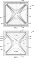
- FIG. 3 illustrates the electrical field within an ion trap operated in a balanced mode.
- the e-field is shown at the point in time where there is a positive 500V potential on the X electrodes 302 and a negative 500V potential on the Y electrodes 304.
- the potentials create a near zero e-potential at points equidistant between an X electrode 302 and a Y electrode 304, as shown by line 306. This creates a near-zero e-field region 308 near the centerline of the LIT that can be ideal for capturing and retaining of ions.
- ions can be scanned out from the LIT to be processed in post-ejection event. It can be important to contain the kinetic energy distribution (KED) in a narrow range. Preferably the KED width should be within tens of electron-volts or less. In normal LIT operation, the KED width can vary between hundreds and thousands of eV.
- Using an unbalanced RF mode for ion ejection can improve the KED by removing the negative effect of post ejection KE modulation by an RF voltage applied to the slotted RF rod (X electrode) the ion pass through.
- the unbalanced RF mode is inferior for ion injection because of non-zero e-field on the centerline of ion injection.
- Figures 4 and 5 illustrate the electrical field within an ion trap operated in an unbalanced mode.
- the same difference between the Y electrodes 304 and the X electrodes 302 can be required to maintain the trapping potential within the LIT.
- the X electrodes 302 are held at a near 0V potential while the RF is applied entirely to the Y electrodes 304.
- Figure 4 shows the e-field at the point in time where there is a positive 1 000V potential on the Y electrodes 304
- Figure 5 shows the e-field at a point in time where there is a negative 1000V potential on the Y electrodes 304.
- the potentials create a significant e-field (approximately half the voltage applied to the Y electrodes 304) at points equidistant between an X electrode 302 and a Y electrode 304, as shown by line 306.
- the region 308 near the centerline of the LIT can experience drastic swings in the potential from a positive 500V in Figure 4 to a negative 500V in Figure 5 .
- Such significant variability in the centerline potential can make it difficult to efficiently trap incoming ions.
- ions are effected primarily by the difference between the X electrodes 302 and the Y electrodes 304 rather than the absolute magnitude of the centerline.
- FIG. 6 illustrates a method for operating the LIT.
- a balanced trapping field can be applied, and at 604, ions can be supplied to the ion trap.
- the ions can be trapped within the ion trap.
- the ion trap can transition to an unbalanced trapping field, and, after the transition is complete, the ions can be selectively ejected from the ion trap while an unbalanced trapping field is applied.
- the ions can be selectively ejected from the ion trap using an excitation waveform that is targeted to ions having a particular mass-to-charge ratio.
- Figure 7 is a timing diagram illustrating the potentials applied to the electrodes on the LIT.
- the LIT is operated in balanced mode with an AC frequency waveform applied to both the X and Y electrodes.
- the AC frequency waveform applied to the Y electrodes is phase shifted 180 degree from the AC frequency waveform applied to the X electrodes.
- the AC voltage can be in a frequency range of between about 100 kHz and about 600 kHz, such as between about 200 kHz and about 300 kHz.
- the AC voltage can be in frequency range of between about 300 kHz and about 400 kHz or between about 400 kHz and about 500 kHz or between about 500 kHz and about 600 kHz.
- the AC voltage can be less than about 400 V 0-P , such as less than about 200 V 0-P.
- the LIT transitions from balanced mode to unbalanced mode.
- the AC frequency waveform is ramped down while an RF frequency waveform is ramped up on the Y electrodes.
- the RF voltage can be in a frequency range of between about 750 kHz and about 1500 kHz.
- the unbalanced mode can be maintained while cooling the ions to reduce their kinetic energy and while ejecting ions.
- the ions can be cooled such that the kinetic energy spread of ions before ejection from the linear ion trap can be less than about 5.0 eV, such as less than about 2.5 eV, such as less than about 0.5 eV, even less than about 0.2 eV.
- the AC frequency waveform can be applied an analog waveform, such as a sine wave.
- the AC frequency waveform can be applied as a a digital waveform of the same frequency and amplitude.
- the LIT can be switched back to balanced mode prior to the next injection (not shown). However, since trapping of ions is not important when switching back to balanced mode, there is no need to ramp the waveforms and the transition can be relatively abrupt by turning the RF frequency waveform off and turning the AC frequency waveform on.
- An AC frequency used for the injection event can be significantly lower than RF frequency required for analytical operation of the LIT in ion isolation and scan-out event. This can reduce the need for a second resonance-based system to provide RF frequency potentials to the X electrodes. Instead the trapping AC can be applied in a non-resonant mode.
- the efficiency of ion injection can be controlled by choosing optimal range of q factors. Its value is proportional to RF voltage on rods and inversely proportional to m/z and square of frequency. Dropping the frequency by a factor of 2-5 allows a reduction in voltage on electrodes by a factor of 4-25 keeping the value of q-factor. That frequency range is typically referred to as the AC range.
- Operating with AC voltages on electrodes at or below 400 V 0-P such as less than about 200 V 0-P , allows for usage of non-resonant circuits to generate the AC. This, in turn, can give good control on turning on, linear ramp and switching off the AC independent of RF circuit operation. There can be a lower total dissipated RF power as well.
- a ramp down time for the AC voltage can be less than about 1.5 ms and a ramp up time for the RF voltage can be between about 0.8 ms and about 2.5 ms.
- FIG 8 is an electrical diagram of an exemplary voltage supply 800 to supply the necessary voltages to ion trap 200.
- the voltage supply 800 can include RF amplifier 802, DC offset source 804, AC source 806, AC source 808, and auxiliary supply 810.
- DC offset source 804 can provide a DC offset on the Y rods between the front 235, center 230, and back 240 portions of the ion trap 200.
- it can be desirable to have an elevated DC voltage for the front 23 5 and back 240 portions and a relatively lower DC voltage for the center 230 portion to create a well to trap ions in the z direction.
- AC source 806 can provide the AC voltage to the Y rods 205 and 210 and AC Source 808 can provide the AC voltage to the x rods 215 and 220.
- main RF amplified 802 can provide the RF voltage to Y rods 205 and 210.
- auxiliary supply 810 can provide the excitation waveform to the X rods 215 and 220 to selectively eject ions from the trap.
- Voltage supply 800 can further include low pass filter 812 to reduce noise on the main RF circuit, filter 814 to block RF on the DC offset circuit, and filter choke and step-up transformers 816, 818, and 820 to reduce noise and increase the voltage of the balanced AC circuits and the auxiliary circuit.
- Voltage supply 800 can further include transformers 822, 824, and 826 to couple the sources to ion trap 200.
- Transformer 824 couples AC supply 806 to the front 235, center 230, and back 240 sections of Y rods 205 and 210.
- Transformer 822 couples the RF amplifier 802 to lines from the DC offset source 804 and AC source 806.
- Transformer 826 couples AC source 808 and auxiliary source 820 to the X rods 215 and 220.
- Voltage supply 800 also includes capacitors 828 and 830 so the capacitance of each circuit can be matched.
- FIG 9 is a block diagram that illustrates a computer system 900, upon which embodiments of the present teachings may be implemented as which may incorporate or communicate with a system controller, for example controller 110 shown in Figure. 1 , such that the operation of components of the associated mass spectrometer may be adjusted in accordance with calculations or determinations made by computer system 900.
- computer system 900 can include a bus 902 or other communication mechanism for communicating information, and a processor 904 coupled with bus 902 for processing information.
- computer system 900 can also include a memory 906, which can be a random access memory (RAM) or other dynamic storage device, coupled to bus 902, and instructions to be executed by processor 904.
- RAM random access memory
- Memory 906 also can be used for storing temporary variables or other intermediate information during execution of instructions to be executed by processor 904.
- computer system 900 can further include a read only memory (ROM) 908 or other static storage device coupled to bus 902 for storing static information and instructions for processor 904.
- ROM read only memory
- a storage device 910 such as a magnetic disk or optical disk, can be provided and coupled to bus 902 for storing information and instructions.
- computer system 900 can be coupled via bus 902 to a display 912, such as a cathode ray tube (CRT) or liquid crystal display (LCD), for displaying information to a computer user.
- a display 912 such as a cathode ray tube (CRT) or liquid crystal display (LCD)
- An input device 914 can be coupled to bus 902 for communicating information and command selections to processor 904.
- a cursor control 916 such as a mouse, a trackball or cursor direction keys for communicating direction information and command selections to processor 904 and for controlling cursor movement on display 912.
- This input device typically has two degrees of freedom in two axes, a first axis (i.e., x) and a second axis (i.e., y), that allows the device to specify positions in a plane.
- a computer system 900 can perform the present teachings. Consistent with certain implementations of the present teachings, results can be provided by computer system 900 in response to processor 904 executing one or more sequences of one or more instructions contained in memory 906. Such instructions can be read into memory 906 from another computer-readable medium, such as storage device 910. Execution of the sequences of instructions contained in memory 906 can cause processor 904 to perform the processes described herein. In various embodiments, instructions in the memory can sequence the use of various combinations of logic gates available within the processor to perform the processes describe herein. Alternatively hard-wired circuitry can be used in place of or in combination with software instructions to implement the present teachings. In various embodiments, the hard-wired circuitry can include the necessary logic gates, operated in the necessary sequence to perform the processes described herein. Thus, implementations of the present teachings are not limited to any specific combination of hardware circuitry and software.
- the specification may have presented a method and/or process as a particular sequence of steps. However, to the extent that the method or process does not rely on the particular order of steps set forth herein, the method or process should not be limited to the particular sequence of steps described. As one of ordinary skill in the art would appreciate, other sequences of steps may be possible. Therefore, the particular order of the steps set forth in the specification should not be construed as limitations on the claims.
- Typical mass range of precursor ions in bottom-up Proteomics can be 400-850 amu. A more extended range can be 400-1200 amu.
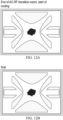
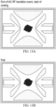
- Figures 10A, 10B , 11A, 11B , 12A, 12B , 13A, 13B , 14A, 14B , 15A, and 15B show x-y the simulation results (SIMION) on efficiency of ion trapping after injection of various size ions within the range of 400-1200 amu.
- the timing is as follows: injection for 500 us, transition period when AC is ramped down for 500 us and RF is ramped up 1200 us. At the end of ramp-up event, RF remained constant. Total time with the final cool-down event - 2500 us.
- AC frequencies are 160 kHz.
- Figure 10A and 10B show the results for ions of 400 amu.
- Figure 11A and 11B show the results for ions of 550 amu.
- Figure 12A and 12B show the results for ions of 700 amu.
- Figure 13A and 13B show the results for ions of 850 amu.
- Figure 14A and 14B show the results for ions of 1000 amu.
- Figure 15A and 15B show the results for ions of 1200 amu.
- Figure 16 is a graph of the voltage (V 0-p ) needed for trapping ions using a balanced AC waveform.
- 110 V 0-p is used as a benchmark based on the available AC voltage on commercially available mass spectrometer systems with a LIT.
- a supplementary AC system capable of providing 110 V 0-p can work across the mass range 400-850 amu at frequencies up to 300 kHz, q from 0.3 to 0.6.
- the upper q value would be ⁇ 0.55 at frequency 300 kHz.
- the normal mass range up to 850 amu allows operating at q up to 0.45 and for the extended mass range q limit will be 0.3.
- increasing the available AC voltage could achieve a broader operating range.
- the normal mass range up to 850 amu allows operating at q up to 0.55 and for the extended mass range q limit will be 0.4 at frequencies of up to 500 kHz.
- the extended mass range allows operating at a q limit above 0.6 at frequencies of up to 500 kHz.
- Figure 17 illustrates the trapping efficiency at the low end of the mass range (400 amu) at a frequency of 0.16 Mhz. Below a q of about 0.4, there can be significant losses of low mass ions, with almost no loss occurring at q greater than about 0.45.
Landscapes
- Chemical & Material Sciences (AREA)
- Analytical Chemistry (AREA)
- Electron Tubes For Measurement (AREA)
- Other Investigation Or Analysis Of Materials By Electrical Means (AREA)
Claims (11)
- Dispositif de piégeage d'ions sélectif en masse comprenant :
un piège à ions linéaire (200) comportant :une pluralité d'électrodes de piège espacées les unes des autres et entourant un intérieur de piège, la pluralité d'électrodes de piège (205, 210, 215, 220) comportant une première paire d'électrodes de piège (302) et une seconde paire d'électrodes de piège (304), au moins une première électrode de piège de la première paire d'électrodes de piège (302) comportant une ouverture de sortie de piège (245), les électrodes de piège étant configurées pour générer un champ de piégeage quadripolaire dans l'intérieur de piège et pour une éjection sélective en masse d'ions de l'intérieur de piège ;une circuiterie de commande RF configurée pour :pendant une première période de temps, appliquer une tension alternative équilibrée aux électrodes de piège (302, 304) de telle sorte qu'une première tension alternative appliquée à la première paire d'électrodes de piège (302) est de signe opposé à une seconde tension alternative à la seconde paire d'électrodes de piège (304), les première et secondes tensions alternative étant de sensiblement la même amplitude, dans lequel la tension alternative équilibrée appliquée pendant la première période de temps est dans une plage de fréquence comprise entre environ 100 kHz et environ 600 kHz ;pendant une seconde période de temps, appliquer une tension RF à la seconde paire d'électrodes de piège et maintenir la première paire d'électrodes de piège à un potentiel proche de 0 V, dans lequel la tension RF est dans une plage de fréquences comprise entre environ 750 kHz et environ 1500 kHz ;pendant une période de transition entre la première période de temps et la seconde période de temps, diminuer la tension alternative équilibrée et augmenter de manière synchrone la tension RF en maintenant le champ de piégeage total suffisamment fort pour retenir des ions mais pas trop fort pour éjecter des ions, dans lequel ces deux rampes démarrent ensemble ; etéjecter des ions du piège à ions linéaire (200) après la seconde période de temps. - Dispositif de piégeage d'ions sélectif en masse selon la revendication 1, dans lequel des ions entrent dans le piège (200) pendant la première période de temps.
- Dispositif de piégeage d'ions sélectif en masse selon l'une quelconque des revendications précédentes, dans lequel un étalement d'énergie cinétique d'ions avant l'éjection du piège à ions linéaire (200) est inférieur à environ 5,0 eV.
- Dispositif de piégeage d'ions sélectif en masse selon l'une quelconque des revendications précédentes, dans lequel un champ électrique sur une ligne centrale du piège à ions (200) linéaire est proche de zéro pendant la première période de temps.
- Dispositif de piégeage d'ions sélectif en masse selon l'une quelconque des revendications précédentes, dans lequel la tension alternative équilibrée est inférieure à environ 400 V0-P ou inférieure à environ 200 V0-P.
- Dispositif de piégeage d'ions sélectif en masse selon l'une quelconque des revendications précédentes, dans lequel, pendant la période de transition, un temps de diminution de la tension alternative est inférieur à environ 1,5 ms et un temps d'augmentation de la tension RF entre environ 0,8 ms et environ 2,5 ms.
- Procédé permettant d'identifier des composants d'un échantillon comprenant : la fourniture d'ions à un piège à ions (200) linéaire sélectif en masse, le piège à ions (200) comportant une pluralité d'électrodes de piège (205, 210, 215, 220) espacées les unes des autres et entourant un intérieur de piège, les électrodes de piège étant configurées pour générer un champ de piégeage quadripolaire dans l'intérieur de piège, la pluralité d'électrodes de piège comportant une première paire d'électrodes de piège et une seconde paire d'électrodes de piège, au moins une première électrode de piège de la première paire d'électrodes de piège comportant une ouverture de sortie de piège ;le piégeage des ions au sein d'un champ de piégeage équilibré en appliquant une tension alternative équilibrée aux électrodes de piège de telle sorte qu'une première tension alternative appliquée à la première paire d'électrodes de piège est de signe opposé à une seconde tension alternative appliquée à la seconde paire d'électrodes de piège, les première et seconde tensions alternatives étant de sensiblement la même amplitude, dans lequel la tension alternative équilibrée appliquée est dans une plage de fréquences comprise entre environ 100 kHz et environ 600 kHz ;la transition entre le champ de piégeage équilibré à un champ de piégeage déséquilibré, le champ de piégeage déséquilibré étant généré à l'aide d'une tension RF appliquée à la seconde paire d'électrodes de piège tout en maintenant la première paire d'électrodes de piège à un potentiel proche de 0 V, dans lequel la tension RF est dans une plage de fréquences comprise entre environ 750 kHz et environ 1500 kHz, dans lequel la transition entre le champ de piégeage équilibré et le champ de piégeage déséquilibré comporte une diminution de la tension alternative équilibrée de manière synchrone avec une augmentation de la tension RF tout en maintenant le champ de piégeage total suffisamment fort pour retenir des ions mais pas trop fort pour éjecter des ions, dans lequel ces deux rampes démarrent ensemble ; etle maintien du champ de piégeage déséquilibré tout en éjectant de manière sélective des ions de l'intérieur de piège sur la base de leur masse à l'aide d'une tension RF auxiliaire.
- Procédé selon la revendication 7, dans lequel un étalement d'énergie cinétique d'ions avant l'éjection à partir du piège à ions linéaire est inférieur à environ 5,0 eV.
- Procédé selon l'une quelconque des revendications 7 et 8, dans lequel un champ électrique sur une ligne centrale du piège à ions linéaire est proche de zéro lors du piégeage des ions dans le champ de piégeage équilibré.
- Procédé selon l'une quelconque des revendications 7 à 9 dans lequel le champ de piégeage équilibré est généré à l'aide d'une tension alternative inférieure à environ 400 V0-P ou moins d'environ 200 V0-P.
- Procédé selon l'une quelconque des revendications 7 à 10, dans lequel la transition comporte le temps diminution de la tension alternative inférieur à environ 1,5 ms et un temps d'augmentation de la tension RF entre environ 0,8 ms et environ 2,5 ms.
Applications Claiming Priority (1)
| Application Number | Priority Date | Filing Date | Title |
|---|---|---|---|
| US16/552,614 US11004672B2 (en) | 2019-08-27 | 2019-08-27 | Systems and methods of operation of linear ion traps in dual balanced AC/unbalanced RF mode for 2D mass spectrometry |
Publications (2)
| Publication Number | Publication Date |
|---|---|
| EP3787005A1 EP3787005A1 (fr) | 2021-03-03 |
| EP3787005B1 true EP3787005B1 (fr) | 2024-03-20 |
Family
ID=72242948
Family Applications (1)
| Application Number | Title | Priority Date | Filing Date |
|---|---|---|---|
| EP20192743.1A Active EP3787005B1 (fr) | 2019-08-27 | 2020-08-25 | Systèmes et procédés de fonctionnement de pièges à ions linéaires en mode double ca équilibré/rf non équilibré pour la spectrométrie de masse 2d |
Country Status (3)
| Country | Link |
|---|---|
| US (3) | US11004672B2 (fr) |
| EP (1) | EP3787005B1 (fr) |
| CN (1) | CN112447490B (fr) |
Families Citing this family (1)
| Publication number | Priority date | Publication date | Assignee | Title |
|---|---|---|---|---|
| US12041864B2 (en) | 2021-10-01 | 2024-07-16 | Paul Scherrer Institut | Method and device for storing free atoms, molecules and ions in a contact-less, albeit well-defined near surface arrangement |
Family Cites Families (19)
| Publication number | Priority date | Publication date | Assignee | Title |
|---|---|---|---|---|
| US4749860A (en) | 1986-06-05 | 1988-06-07 | Finnigan Corporation | Method of isolating a single mass in a quadrupole ion trap |
| US5420425A (en) * | 1994-05-27 | 1995-05-30 | Finnigan Corporation | Ion trap mass spectrometer system and method |
| US5714755A (en) | 1996-03-01 | 1998-02-03 | Varian Associates, Inc. | Mass scanning method using an ion trap mass spectrometer |
| US5747801A (en) | 1997-01-24 | 1998-05-05 | University Of Florida | Method and device for improved trapping efficiency of injected ions for quadrupole ion traps |
| US7034293B2 (en) | 2004-05-26 | 2006-04-25 | Varian, Inc. | Linear ion trap apparatus and method utilizing an asymmetrical trapping field |
| US7582864B2 (en) * | 2005-12-22 | 2009-09-01 | Leco Corporation | Linear ion trap with an imbalanced radio frequency field |
| US7365318B2 (en) * | 2006-05-19 | 2008-04-29 | Thermo Finnigan Llc | System and method for implementing balanced RF fields in an ion trap device |
| JP5081436B2 (ja) * | 2006-11-24 | 2012-11-28 | 株式会社日立ハイテクノロジーズ | 質量分析装置及び質量分析方法 |
| GB0800526D0 (en) * | 2008-01-11 | 2008-02-20 | Micromass Ltd | Mass spectrometer |
| US7872228B1 (en) * | 2008-06-18 | 2011-01-18 | Bruker Daltonics, Inc. | Stacked well ion trap |
| GB201116026D0 (en) * | 2011-09-16 | 2011-10-26 | Micromass Ltd | Performance improvements for rf-only quadrupole mass filters and linear quadrupole ion traps with axial ejection |
| CN103367094B (zh) * | 2012-03-31 | 2016-12-14 | 株式会社岛津制作所 | 离子阱分析器以及离子阱质谱分析方法 |
| US9653279B2 (en) * | 2013-02-18 | 2017-05-16 | Micromass Uk Limited | Device allowing improved reaction monitoring of gas phase reactions in mass spectrometers using an auto ejection ion trap |
| WO2014191748A1 (fr) * | 2013-05-31 | 2014-12-04 | Micromass Uk Limited | Spectromètre de masse compact |
| JP2015011801A (ja) | 2013-06-27 | 2015-01-19 | 株式会社日立ハイテクノロジーズ | 質量分析方法及び質量分析装置 |
| US10186412B2 (en) * | 2014-06-12 | 2019-01-22 | Washington State University | Digital waveform manipulations to produce MSn collision induced dissociation |
| US10861687B2 (en) * | 2015-04-23 | 2020-12-08 | Micromass Uk Limited | Separating ions in an ion trap |
| US9978578B2 (en) * | 2016-02-03 | 2018-05-22 | Fasmatech Science & Technology Ltd. | Segmented linear ion trap for enhanced ion activation and storage |
| US9865446B2 (en) * | 2016-05-26 | 2018-01-09 | Thermo Finnigan Llc | Systems and methods for reducing the kinetic energy spread of ions radially ejected from a linear ion trap |
-
2019
- 2019-08-27 US US16/552,614 patent/US11004672B2/en active Active
-
2020
- 2020-08-25 EP EP20192743.1A patent/EP3787005B1/fr active Active
- 2020-08-25 CN CN202010866897.1A patent/CN112447490B/zh active Active
-
2021
- 2021-04-13 US US17/229,615 patent/US11651948B2/en active Active
-
2023
- 2023-04-27 US US18/308,265 patent/US12040174B2/en active Active
Also Published As
| Publication number | Publication date |
|---|---|
| US12040174B2 (en) | 2024-07-16 |
| EP3787005A1 (fr) | 2021-03-03 |
| US20210066062A1 (en) | 2021-03-04 |
| CN112447490B (zh) | 2024-05-28 |
| US20210233763A1 (en) | 2021-07-29 |
| US20230260776A1 (en) | 2023-08-17 |
| CN112447490A (zh) | 2021-03-05 |
| US11651948B2 (en) | 2023-05-16 |
| US11004672B2 (en) | 2021-05-11 |
Similar Documents
| Publication | Publication Date | Title |
|---|---|---|
| US7145139B2 (en) | Confining positive and negative ions with fast oscillating electric potentials | |
| EP1789990B1 (fr) | Fragmentation par impulsion à valeur q élevée dans des pièges à ions | |
| JP4312708B2 (ja) | 衝突エネルギーを変化させることによる質量分析における広いイオンフラグメント化範囲を得る方法 | |
| EP2113129B1 (fr) | Spectrometre de masse | |
| US6949743B1 (en) | High-Q pulsed fragmentation in ion traps | |
| US8637816B1 (en) | Systems and methods for MS-MS-analysis | |
| JP5384749B2 (ja) | 補助rf電圧を印加することによるイオンガイドからの質量対電荷比選択的な放出 | |
| JP2009502017A5 (fr) | ||
| US7847240B2 (en) | Mass spectroscopy system and method including an excitation gate | |
| GB2405526A (en) | Electron-ion fragmentation reactions in multipolar radiofrequency fields | |
| JP2015503825A (ja) | イオントラップから低m/z比を有するイオンを抽出する方法 | |
| US20040245448A1 (en) | Methods and apparatus for electron or positron capture dissociation | |
| US12040174B2 (en) | Systems and methods of operation of linear ion traps in dual balanced AC/unbalanced RF mode for 2D mass spectrometry | |
| March et al. | Radio frequency quadrupole technology: evolution and contributions to mass spectrometry | |
| EP3357080B1 (fr) | Piège à ions linéaire à éjection axiale sélective de masse | |
| JP2023500646A (ja) | フーリエ変換質量分析の方法およびシステム | |
| CN113366608A (zh) | 傅立叶变换质谱仪及使用其分析的方法 | |
| JP3960306B2 (ja) | イオントラップ装置 |
Legal Events
| Date | Code | Title | Description |
|---|---|---|---|
| PUAI | Public reference made under article 153(3) epc to a published international application that has entered the european phase |
Free format text: ORIGINAL CODE: 0009012 |
|
| STAA | Information on the status of an ep patent application or granted ep patent |
Free format text: STATUS: THE APPLICATION HAS BEEN PUBLISHED |
|
| AK | Designated contracting states |
Kind code of ref document: A1 Designated state(s): AL AT BE BG CH CY CZ DE DK EE ES FI FR GB GR HR HU IE IS IT LI LT LU LV MC MK MT NL NO PL PT RO RS SE SI SK SM TR |
|
| AX | Request for extension of the european patent |
Extension state: BA ME |
|
| STAA | Information on the status of an ep patent application or granted ep patent |
Free format text: STATUS: REQUEST FOR EXAMINATION WAS MADE |
|
| 17P | Request for examination filed |
Effective date: 20210903 |
|
| RBV | Designated contracting states (corrected) |
Designated state(s): AL AT BE BG CH CY CZ DE DK EE ES FI FR GB GR HR HU IE IS IT LI LT LU LV MC MK MT NL NO PL PT RO RS SE SI SK SM TR |
|
| GRAP | Despatch of communication of intention to grant a patent |
Free format text: ORIGINAL CODE: EPIDOSNIGR1 |
|
| STAA | Information on the status of an ep patent application or granted ep patent |
Free format text: STATUS: GRANT OF PATENT IS INTENDED |
|
| GRAJ | Information related to disapproval of communication of intention to grant by the applicant or resumption of examination proceedings by the epo deleted |
Free format text: ORIGINAL CODE: EPIDOSDIGR1 |
|
| GRAP | Despatch of communication of intention to grant a patent |
Free format text: ORIGINAL CODE: EPIDOSNIGR1 |
|
| INTG | Intention to grant announced |
Effective date: 20231023 |
|
| INTG | Intention to grant announced |
Effective date: 20231031 |
|
| GRAS | Grant fee paid |
Free format text: ORIGINAL CODE: EPIDOSNIGR3 |
|
| GRAA | (expected) grant |
Free format text: ORIGINAL CODE: 0009210 |
|
| STAA | Information on the status of an ep patent application or granted ep patent |
Free format text: STATUS: THE PATENT HAS BEEN GRANTED |
|
| AK | Designated contracting states |
Kind code of ref document: B1 Designated state(s): AL AT BE BG CH CY CZ DE DK EE ES FI FR GB GR HR HU IE IS IT LI LT LU LV MC MK MT NL NO PL PT RO RS SE SI SK SM TR |
|
| REG | Reference to a national code |
Ref country code: GB Ref legal event code: FG4D |
|
| REG | Reference to a national code |
Ref country code: CH Ref legal event code: EP |
|
| REG | Reference to a national code |
Ref country code: DE Ref legal event code: R096 Ref document number: 602020027424 Country of ref document: DE |
|
| REG | Reference to a national code |
Ref country code: IE Ref legal event code: FG4D |
|
| PG25 | Lapsed in a contracting state [announced via postgrant information from national office to epo] |
Ref country code: LT Free format text: LAPSE BECAUSE OF FAILURE TO SUBMIT A TRANSLATION OF THE DESCRIPTION OR TO PAY THE FEE WITHIN THE PRESCRIBED TIME-LIMIT Effective date: 20240320 |
|
| REG | Reference to a national code |
Ref country code: LT Ref legal event code: MG9D |
|
| PG25 | Lapsed in a contracting state [announced via postgrant information from national office to epo] |
Ref country code: GR Free format text: LAPSE BECAUSE OF FAILURE TO SUBMIT A TRANSLATION OF THE DESCRIPTION OR TO PAY THE FEE WITHIN THE PRESCRIBED TIME-LIMIT Effective date: 20240621 |
|
| PG25 | Lapsed in a contracting state [announced via postgrant information from national office to epo] |
Ref country code: RS Free format text: LAPSE BECAUSE OF FAILURE TO SUBMIT A TRANSLATION OF THE DESCRIPTION OR TO PAY THE FEE WITHIN THE PRESCRIBED TIME-LIMIT Effective date: 20240620 Ref country code: HR Free format text: LAPSE BECAUSE OF FAILURE TO SUBMIT A TRANSLATION OF THE DESCRIPTION OR TO PAY THE FEE WITHIN THE PRESCRIBED TIME-LIMIT Effective date: 20240320 |
|
| REG | Reference to a national code |
Ref country code: NL Ref legal event code: MP Effective date: 20240320 |
|
| PG25 | Lapsed in a contracting state [announced via postgrant information from national office to epo] |
Ref country code: RS Free format text: LAPSE BECAUSE OF FAILURE TO SUBMIT A TRANSLATION OF THE DESCRIPTION OR TO PAY THE FEE WITHIN THE PRESCRIBED TIME-LIMIT Effective date: 20240620 Ref country code: NO Free format text: LAPSE BECAUSE OF FAILURE TO SUBMIT A TRANSLATION OF THE DESCRIPTION OR TO PAY THE FEE WITHIN THE PRESCRIBED TIME-LIMIT Effective date: 20240620 Ref country code: LT Free format text: LAPSE BECAUSE OF FAILURE TO SUBMIT A TRANSLATION OF THE DESCRIPTION OR TO PAY THE FEE WITHIN THE PRESCRIBED TIME-LIMIT Effective date: 20240320 Ref country code: HR Free format text: LAPSE BECAUSE OF FAILURE TO SUBMIT A TRANSLATION OF THE DESCRIPTION OR TO PAY THE FEE WITHIN THE PRESCRIBED TIME-LIMIT Effective date: 20240320 Ref country code: GR Free format text: LAPSE BECAUSE OF FAILURE TO SUBMIT A TRANSLATION OF THE DESCRIPTION OR TO PAY THE FEE WITHIN THE PRESCRIBED TIME-LIMIT Effective date: 20240621 Ref country code: FI Free format text: LAPSE BECAUSE OF FAILURE TO SUBMIT A TRANSLATION OF THE DESCRIPTION OR TO PAY THE FEE WITHIN THE PRESCRIBED TIME-LIMIT Effective date: 20240320 Ref country code: BG Free format text: LAPSE BECAUSE OF FAILURE TO SUBMIT A TRANSLATION OF THE DESCRIPTION OR TO PAY THE FEE WITHIN THE PRESCRIBED TIME-LIMIT Effective date: 20240320 |
|
| REG | Reference to a national code |
Ref country code: AT Ref legal event code: MK05 Ref document number: 1668600 Country of ref document: AT Kind code of ref document: T Effective date: 20240320 |
|
| PG25 | Lapsed in a contracting state [announced via postgrant information from national office to epo] |
Ref country code: SE Free format text: LAPSE BECAUSE OF FAILURE TO SUBMIT A TRANSLATION OF THE DESCRIPTION OR TO PAY THE FEE WITHIN THE PRESCRIBED TIME-LIMIT Effective date: 20240320 Ref country code: LV Free format text: LAPSE BECAUSE OF FAILURE TO SUBMIT A TRANSLATION OF THE DESCRIPTION OR TO PAY THE FEE WITHIN THE PRESCRIBED TIME-LIMIT Effective date: 20240320 |
|
| PG25 | Lapsed in a contracting state [announced via postgrant information from national office to epo] |
Ref country code: NL Free format text: LAPSE BECAUSE OF FAILURE TO SUBMIT A TRANSLATION OF THE DESCRIPTION OR TO PAY THE FEE WITHIN THE PRESCRIBED TIME-LIMIT Effective date: 20240320 |