EP3786923A2 - Object detection apparatus, and storage medium - Google Patents
Object detection apparatus, and storage medium Download PDFInfo
- Publication number
- EP3786923A2 EP3786923A2 EP20182461.2A EP20182461A EP3786923A2 EP 3786923 A2 EP3786923 A2 EP 3786923A2 EP 20182461 A EP20182461 A EP 20182461A EP 3786923 A2 EP3786923 A2 EP 3786923A2
- Authority
- EP
- European Patent Office
- Prior art keywords
- information
- vehicle
- objects
- group
- object detection
- Prior art date
- Legal status (The legal status is an assumption and is not a legal conclusion. Google has not performed a legal analysis and makes no representation as to the accuracy of the status listed.)
- Granted
Links
- 238000001514 detection method Methods 0.000 title claims abstract description 84
- 238000003860 storage Methods 0.000 title description 10
- 238000000034 method Methods 0.000 claims description 45
- 230000008569 process Effects 0.000 claims description 30
- 238000004590 computer program Methods 0.000 claims description 2
- 230000005540 biological transmission Effects 0.000 description 42
- 230000004048 modification Effects 0.000 description 19
- 238000012986 modification Methods 0.000 description 19
- 238000012545 processing Methods 0.000 description 18
- 230000006870 function Effects 0.000 description 14
- 230000008901 benefit Effects 0.000 description 6
- 238000005516 engineering process Methods 0.000 description 4
- 230000000694 effects Effects 0.000 description 3
- 239000013589 supplement Substances 0.000 description 3
- 230000008859 change Effects 0.000 description 2
- 230000002093 peripheral effect Effects 0.000 description 2
- 239000004065 semiconductor Substances 0.000 description 2
- 238000005452 bending Methods 0.000 description 1
- 238000004891 communication Methods 0.000 description 1
- 230000001419 dependent effect Effects 0.000 description 1
- 238000009826 distribution Methods 0.000 description 1
- 230000010354 integration Effects 0.000 description 1
- 238000004519 manufacturing process Methods 0.000 description 1
- 230000004044 response Effects 0.000 description 1
- 238000000926 separation method Methods 0.000 description 1
Images


Classifications
-
- G—PHYSICS
- G01—MEASURING; TESTING
- G01S—RADIO DIRECTION-FINDING; RADIO NAVIGATION; DETERMINING DISTANCE OR VELOCITY BY USE OF RADIO WAVES; LOCATING OR PRESENCE-DETECTING BY USE OF THE REFLECTION OR RERADIATION OF RADIO WAVES; ANALOGOUS ARRANGEMENTS USING OTHER WAVES
- G01S13/00—Systems using the reflection or reradiation of radio waves, e.g. radar systems; Analogous systems using reflection or reradiation of waves whose nature or wavelength is irrelevant or unspecified
-
- G—PHYSICS
- G08—SIGNALLING
- G08G—TRAFFIC CONTROL SYSTEMS
- G08G1/00—Traffic control systems for road vehicles
- G08G1/09—Arrangements for giving variable traffic instructions
- G08G1/0962—Arrangements for giving variable traffic instructions having an indicator mounted inside the vehicle, e.g. giving voice messages
- G08G1/0967—Systems involving transmission of highway information, e.g. weather, speed limits
- G08G1/096708—Systems involving transmission of highway information, e.g. weather, speed limits where the received information might be used to generate an automatic action on the vehicle control
- G08G1/096725—Systems involving transmission of highway information, e.g. weather, speed limits where the received information might be used to generate an automatic action on the vehicle control where the received information generates an automatic action on the vehicle control
-
- B—PERFORMING OPERATIONS; TRANSPORTING
- B60—VEHICLES IN GENERAL
- B60W—CONJOINT CONTROL OF VEHICLE SUB-UNITS OF DIFFERENT TYPE OR DIFFERENT FUNCTION; CONTROL SYSTEMS SPECIALLY ADAPTED FOR HYBRID VEHICLES; ROAD VEHICLE DRIVE CONTROL SYSTEMS FOR PURPOSES NOT RELATED TO THE CONTROL OF A PARTICULAR SUB-UNIT
- B60W30/00—Purposes of road vehicle drive control systems not related to the control of a particular sub-unit, e.g. of systems using conjoint control of vehicle sub-units, or advanced driver assistance systems for ensuring comfort, stability and safety or drive control systems for propelling or retarding the vehicle
- B60W30/08—Active safety systems predicting or avoiding probable or impending collision or attempting to minimise its consequences
- B60W30/095—Predicting travel path or likelihood of collision
- B60W30/0956—Predicting travel path or likelihood of collision the prediction being responsive to traffic or environmental parameters
-
- G—PHYSICS
- G01—MEASURING; TESTING
- G01S—RADIO DIRECTION-FINDING; RADIO NAVIGATION; DETERMINING DISTANCE OR VELOCITY BY USE OF RADIO WAVES; LOCATING OR PRESENCE-DETECTING BY USE OF THE REFLECTION OR RERADIATION OF RADIO WAVES; ANALOGOUS ARRANGEMENTS USING OTHER WAVES
- G01S13/00—Systems using the reflection or reradiation of radio waves, e.g. radar systems; Analogous systems using reflection or reradiation of waves whose nature or wavelength is irrelevant or unspecified
- G01S13/66—Radar-tracking systems; Analogous systems
-
- G—PHYSICS
- G01—MEASURING; TESTING
- G01S—RADIO DIRECTION-FINDING; RADIO NAVIGATION; DETERMINING DISTANCE OR VELOCITY BY USE OF RADIO WAVES; LOCATING OR PRESENCE-DETECTING BY USE OF THE REFLECTION OR RERADIATION OF RADIO WAVES; ANALOGOUS ARRANGEMENTS USING OTHER WAVES
- G01S13/00—Systems using the reflection or reradiation of radio waves, e.g. radar systems; Analogous systems using reflection or reradiation of waves whose nature or wavelength is irrelevant or unspecified
- G01S13/88—Radar or analogous systems specially adapted for specific applications
- G01S13/93—Radar or analogous systems specially adapted for specific applications for anti-collision purposes
- G01S13/931—Radar or analogous systems specially adapted for specific applications for anti-collision purposes of land vehicles
-
- G—PHYSICS
- G08—SIGNALLING
- G08G—TRAFFIC CONTROL SYSTEMS
- G08G1/00—Traffic control systems for road vehicles
- G08G1/01—Detecting movement of traffic to be counted or controlled
- G08G1/0104—Measuring and analyzing of parameters relative to traffic conditions
- G08G1/0108—Measuring and analyzing of parameters relative to traffic conditions based on the source of data
- G08G1/0112—Measuring and analyzing of parameters relative to traffic conditions based on the source of data from the vehicle, e.g. floating car data [FCD]
-
- G—PHYSICS
- G08—SIGNALLING
- G08G—TRAFFIC CONTROL SYSTEMS
- G08G1/00—Traffic control systems for road vehicles
- G08G1/01—Detecting movement of traffic to be counted or controlled
- G08G1/0104—Measuring and analyzing of parameters relative to traffic conditions
- G08G1/0108—Measuring and analyzing of parameters relative to traffic conditions based on the source of data
- G08G1/0116—Measuring and analyzing of parameters relative to traffic conditions based on the source of data from roadside infrastructure, e.g. beacons
-
- G—PHYSICS
- G08—SIGNALLING
- G08G—TRAFFIC CONTROL SYSTEMS
- G08G1/00—Traffic control systems for road vehicles
- G08G1/01—Detecting movement of traffic to be counted or controlled
- G08G1/0104—Measuring and analyzing of parameters relative to traffic conditions
- G08G1/0125—Traffic data processing
- G08G1/0133—Traffic data processing for classifying traffic situation
-
- G—PHYSICS
- G08—SIGNALLING
- G08G—TRAFFIC CONTROL SYSTEMS
- G08G1/00—Traffic control systems for road vehicles
- G08G1/01—Detecting movement of traffic to be counted or controlled
- G08G1/04—Detecting movement of traffic to be counted or controlled using optical or ultrasonic detectors
-
- G—PHYSICS
- G08—SIGNALLING
- G08G—TRAFFIC CONTROL SYSTEMS
- G08G1/00—Traffic control systems for road vehicles
- G08G1/09—Arrangements for giving variable traffic instructions
- G08G1/0962—Arrangements for giving variable traffic instructions having an indicator mounted inside the vehicle, e.g. giving voice messages
- G08G1/0968—Systems involving transmission of navigation instructions to the vehicle
- G08G1/096877—Systems involving transmission of navigation instructions to the vehicle where the input to the navigation device is provided by a suitable I/O arrangement
- G08G1/096894—Systems involving transmission of navigation instructions to the vehicle where the input to the navigation device is provided by a suitable I/O arrangement where input is assisted by the navigation device, i.e. the user does not type the complete name of the destination, e.g. using zip codes, telephone numbers, progressively selecting from initial letters
-
- G—PHYSICS
- G08—SIGNALLING
- G08G—TRAFFIC CONTROL SYSTEMS
- G08G1/00—Traffic control systems for road vehicles
- G08G1/16—Anti-collision systems
- G08G1/166—Anti-collision systems for active traffic, e.g. moving vehicles, pedestrians, bikes
-
- B—PERFORMING OPERATIONS; TRANSPORTING
- B60—VEHICLES IN GENERAL
- B60W—CONJOINT CONTROL OF VEHICLE SUB-UNITS OF DIFFERENT TYPE OR DIFFERENT FUNCTION; CONTROL SYSTEMS SPECIALLY ADAPTED FOR HYBRID VEHICLES; ROAD VEHICLE DRIVE CONTROL SYSTEMS FOR PURPOSES NOT RELATED TO THE CONTROL OF A PARTICULAR SUB-UNIT
- B60W50/00—Details of control systems for road vehicle drive control not related to the control of a particular sub-unit, e.g. process diagnostic or vehicle driver interfaces
- B60W50/08—Interaction between the driver and the control system
- B60W50/14—Means for informing the driver, warning the driver or prompting a driver intervention
- B60W2050/146—Display means
-
- B—PERFORMING OPERATIONS; TRANSPORTING
- B60—VEHICLES IN GENERAL
- B60W—CONJOINT CONTROL OF VEHICLE SUB-UNITS OF DIFFERENT TYPE OR DIFFERENT FUNCTION; CONTROL SYSTEMS SPECIALLY ADAPTED FOR HYBRID VEHICLES; ROAD VEHICLE DRIVE CONTROL SYSTEMS FOR PURPOSES NOT RELATED TO THE CONTROL OF A PARTICULAR SUB-UNIT
- B60W2554/00—Input parameters relating to objects
- B60W2554/80—Spatial relation or speed relative to objects
- B60W2554/801—Lateral distance
-
- B—PERFORMING OPERATIONS; TRANSPORTING
- B60—VEHICLES IN GENERAL
- B60W—CONJOINT CONTROL OF VEHICLE SUB-UNITS OF DIFFERENT TYPE OR DIFFERENT FUNCTION; CONTROL SYSTEMS SPECIALLY ADAPTED FOR HYBRID VEHICLES; ROAD VEHICLE DRIVE CONTROL SYSTEMS FOR PURPOSES NOT RELATED TO THE CONTROL OF A PARTICULAR SUB-UNIT
- B60W2554/00—Input parameters relating to objects
- B60W2554/80—Spatial relation or speed relative to objects
- B60W2554/804—Relative longitudinal speed
-
- G—PHYSICS
- G01—MEASURING; TESTING
- G01S—RADIO DIRECTION-FINDING; RADIO NAVIGATION; DETERMINING DISTANCE OR VELOCITY BY USE OF RADIO WAVES; LOCATING OR PRESENCE-DETECTING BY USE OF THE REFLECTION OR RERADIATION OF RADIO WAVES; ANALOGOUS ARRANGEMENTS USING OTHER WAVES
- G01S13/00—Systems using the reflection or reradiation of radio waves, e.g. radar systems; Analogous systems using reflection or reradiation of waves whose nature or wavelength is irrelevant or unspecified
- G01S13/88—Radar or analogous systems specially adapted for specific applications
- G01S13/93—Radar or analogous systems specially adapted for specific applications for anti-collision purposes
- G01S13/931—Radar or analogous systems specially adapted for specific applications for anti-collision purposes of land vehicles
- G01S2013/9327—Sensor installation details
- G01S2013/93271—Sensor installation details in the front of the vehicles
Definitions
- the present disclosure relates to an object detection apparatus that outputs, to an in-vehicle apparatus, information on an object detected by a sensor installed on a vehicle, and a storage medium.
- This object detection apparatus includes a detection unit that detects an object using a radar and a selection unit.
- the detection unit detects a high-threshold object with a reflection intensity higher than a first threshold value and a low-threshold object with a reflection intensity lower than the first threshold value and higher than a second threshold value.
- the selection unit performs selection such that in a case where the sum of the number of candidates for the high-threshold objects detected by the detection unit and the number of candidates for the low-threshold objects is greater than a preset maximum allowable number of objects capable of being output as a detection result, the selection unit selects, as the detection result, high-threshold objects and low-threshold objects such that a higher priority is given to the candidates for high-threshold objects.
- the priority of objects to be detected is determined based on the reflection intensity.
- objects to be detected for a vehicle may be different depending on a traffic environment.
- One non-limiting and exemplary embodiment facilitates providing an object detection apparatus, and a storage medium capable of outputting information on an object depending on a traffic environment.
- the techniques disclosed here feature an object detection apparatus including an input port that receives information on a plurality of objects in surroundings of a vehicle and information on a traffic environment of the vehicle, the plurality of objects being detected by a sensor installed on the vehicle, a controller that determines, based on the information on the plurality of objects and the information on the traffic environment, priority for each of the plurality of objects and determines first information based on the priority in a case where the total amount of information on the plurality of objects is greater than a determined value, the first information being information on part of the plurality of objects, and an output port that outputs the first information to an in-vehicle apparatus that controls the vehicle.
- an object detection apparatus 1 according to an embodiment of the present disclosure is described.
- a vehicle V includes, as apparatuses installed therein, in addition to the object detection apparatus 1 described above, a sensor 3, a traffic environment transmission apparatus 5, and an in-vehicle apparatus 7.
- a sensor 3 a traffic environment transmission apparatus 5
- an in-vehicle apparatus 7 an in-vehicle apparatus 7.
- the data transmission method include Controller Area Network (CAN), Ethernet (registered trademark), etc.
- the sensor 3 is, for example, a millimeter wave radar, and is installed, for example, near the front end of the vehicle V.
- the sensor 3 periodically transmits a radar signal (for example, a radio wave in a millimeter wave band) within a measurable range (in other words, in a visible range).
- a radar signal for example, a radio wave in a millimeter wave band
- a return signal which is a radar signal output and reflected back from an object (target object)
- the sensor 3 executes a known target recognition algorithm.
- the sensor 3 time sequentially transmits target information T associated with each object existing in the surroundings of the vehicle V to the object detection apparatus 1 via the data transmission line 9.
- the target information T includes items such as the direction, the distance, the relative speed, and/or the like of the object with reference to the vehicle V (or the sensor 3).
- the traffic environment transmission apparatus 5 is, for example, a navigation apparatus.
- the traffic environment transmission apparatus 5 is capable of identifying a current location of the vehicle V (more specifically, the current position of the sensor 3) and capable of acquiring network data representing a road distribution expressed typically using links and nodes from a local storage device (not illustrated) or a remote server.
- Each node represents a feature point (an intersection or a bending point) on a road.
- Each link represents a road between each of nodes.
- Each link is assigned various kinds of information on a road, such as a road type or the like. Examples of road types include an expressway, a general road, a road close to an intersection, and the like.
- the traffic environment transmission apparatus 5 identifies, in response to a request from the object detection apparatus 1, a road on which the vehicle V is currently running, and acquires traffic environment information E including a type of the identified road from network data.
- the traffic environment transmission apparatus 5 transmits the acquired traffic environment information E to the object detection apparatus 1 via the data transmission line 9.
- the object detection apparatus 1 is disposed, for example, in an Electronic Control Unit (ECU), and includes an input port 11, a controller 13, and an output port 15.
- ECU Electronic Control Unit
- the input port 11 is an input interface according to the data transmission method described above.
- the input port 11 receives target information T from the sensor 3 and traffic environment information E from the traffic environment transmission apparatus 5. Furthermore, under the control of the controller 13, the input port 11 transfers the received target information T and the traffic environment information E to a main memory 133 of the controller 13.
- the controller 13 includes, for example, a program memory 131, the main memory 133, and a microcomputer 135.
- the program memory 131 is, for example, a non-transitory memory such as EEPROM.
- a program 137 describing a processing procedure (described later with reference to Fig. 3 ) is stored in advance.
- the main memory 133 is, for example, a semiconductor memory such as SRAM.
- the microcomputer 135 executes the program 137 using the main memory 133 or the like as a work area. Basically, the microcomputer 135 transmits all received target information T to the in-vehicle apparatus 7 via the data transmission line 9. However, in a case where it is impossible to transmit all received target information T, the microcomputer 135 selects target information with high priority from the received target information T, and transmits the selected target information with high priority to the in-vehicle apparatus 7 via the data transmission line 9.
- the output port 15 is an output interface according to the data transmission method, and transmits target information T to the in-vehicle apparatus 7 via the data transmission line 9 each time the target information T to be transmitted is determined by the microcomputer 135.
- the in-vehicle apparatus 7 is an apparatus such as a display apparatus, an automatic braking apparatus, or the like installed in the vehicle V, and performs a particular process based on a detection result R received from the output port 15. 1-2. Process performed by controller 13
- the microcomputer 135 executes the program 137 thereby functioning as a target acquirer 171, a determiner 173, a priority assigner 175, a traffic environment acquirer 177 and a target outputter 179, as illustrated in Fig. 2 .
- the object detection apparatus 1 for example, a processing procedure of the microcomputer 135 defined in the program 137.
- the target information T transmitted time-sequentially from the sensor 3 is received by the input port 11.
- the microcomputer 135 functions as the target acquirer 171 and transfers the received target information T to the main memory 133.
- the controller 13 acquires the target information T (step S001 in Fig. 3 ).
- the microcomputer 135 functions as the determiner 173, and determines whether it is possible to transmit all target information T acquired in step S001 to the in-vehicle apparatus 7 (step S003). More specifically, the transmission bandwidth usable in the data transmission from the object detection apparatus 1 to the in-vehicle apparatus 7 is limited to a predetermined fixed value. Furthermore, the transmission from the target information T to the in-vehicle apparatus 7 generally needs to be performed in real time. Thus, in step S003, it is determined whether it is possible to transmit all target information T received by the object detection apparatus 1 to the in-vehicle apparatus 7 using a usable transmission bandwidth within a predetermined period of time. In other words, it is determined whether the data output rate (transmission bandwidth) [bits/sec] at the output port 15 ⁇ output time (predetermine time period) [sec] is larger than the total amount of data [bits] of the acquired target information T.
- step S003 In a case where it is determined in step S003 (by the determiner 173) that it is possible to transmit all target information T (Yes in step S003), then the microcomputer 135 functions as the target outputter 179 and transmits all target information T acquired in step S001 to the in-vehicle apparatus 7 (step S027). After step S027, the microcomputer 135 returns the process to step S001, in which the microcomputer 135 performs a process shown in Fig. 3 on the target information T that the input port 11 newly receives from the sensor 3 via the data transmission line 9.
- step S003 the microcomputer 135 functions as the priority assigner 175 and determines an initial priority for each piece of information included in the whole target information T acquired in step S001 and sorts the pieces of information in the target information T in order of priority from high to low (step S005).
- step S005 for example, the closer the distance between the vehicle V (or the sensor 3) and the object described in a piece of information in the target information T, the higher the priority assigned to the piece in the target information T.
- the microcomputer 135 functions as the traffic environment acquirer 177 and acquires traffic environment information E from the traffic environment transmission apparatus 5.
- the traffic environment information E represents a traffic environment in the surroundings of the vehicle V, and more specifically the traffic environment information E includes information indicating a type of a road on which the vehicle V is currently running (hereinafter referred to as a road type). Examples of road types include an expressway, a general road, a road close to intersection, and the like.
- the traffic environment information E is received by the input port 11.
- the microcomputer 135 transfers the received traffic environment information E to the main memory 133. As a result, the controller 13 acquires the traffic environment information E (step S007).
- the microcomputer 135 functions as the priority assigner 175 and determines whether the road type described in the traffic environment information E is the expressway, the road close to intersection, or the general road (steps S009, S011, and S013).
- step S015 the microcomputer 135 changes the priority of pieces of information included in the target information T currently stored in the main memory 133 such that the priority of a piece of information associated with an oncoming vehicle is reduced by a first predetermined value (step S015).
- This process is performed because expressways each have a center divider and thus oncoming vehicles do not have significant influences on running or driving of the vehicle V.
- the determination as to whether the target information T indicates an oncoming vehicle or not may be performed based a relative speed and a direction described in the target information T.
- the first predetermined value may be properly determined when the object detection apparatus 1 is designed or developed.
- the microcomputer 135 advances the processing flow from step S009 to step S011.
- step S017 the microcomputer 135 advances the processing flow from step S011 to step S017, in which the microcomputer 135 changes the priority of pieces of information included in the target information T currently stored in the main memory 133 such that the priority of a piece of information associated with an oncoming vehicle is increased by a second predetermined value (step S017).
- This process is performed because, on the road close to intersection, oncoming vehicles have significant influences on running or driving of the vehicle V. More specifically, when the vehicle V runs straight or makes a right turn at an intersection, the running or driving of the vehicle V may be influenced by an oncoming vehicle running straight or making a right turn.
- the determination as to whether a piece of information in the target information T indicates an oncoming vehicle or not may be performed based a relative speed and a direction described in the target information T.
- the second predetermined value may be properly determined when the object detection apparatus 1 is designed or developed.
- the microcomputer 135 advances the processing flow from step S011 to step S013.
- the microcomputer 135 advances the processing flow from step S013 to step S019, in which the microcomputer 135 changes the priority of pieces of information included in the target information T currently stored in the main memory 133 such that the priority of a piece of information associated with a vehicle approaching the vehicle V at a high speed is increased by a third predetermined value (step S019).
- This process is performed because the running and the driving of the vehicle V are influenced by moving objects (mainly vehicles) located near the vehicle V and approaching the vehicle V at a high speed.
- the initial priority for each piece of information in the target information T is determined, in step S005, depending on the distance between the vehicle V and the object, and thus, in step S019, the priority is increased for a vehicle approaching the vehicle V at a high speed.
- the determination as to whether a piece of information in the target information T indicates a vehicle approaching the vehicle V at a high speed may be performed based a relative speed and a direction described in the target information T.
- the third predetermined value may be properly determined when the object detection apparatus 1 is designed or developed.
- the microcomputer 135 functions as the target outputter 179 and sorts the pieces of information in the target information T currently stored in the main memory 133 in order of priority from high to low (step S021).
- step S021 the microcomputer 135 functions as the target outputter 179 and selects, from the target information T currently stored in the main memory 133, pieces of information that the object detection apparatus 1 can output to the in-vehicle apparatus 7 within the predetermined time period described above based on the priority assigned to the pieces of information (step S023).
- the microcomputer 135 further functions as the target outputter 179 and sequentially transmits the pieces of information selected in step S023 in the target information T, for example, in order of priority from high to low, to the data transmission line 9 via the output port 15 (step S025).
- the transmitted pieces of information of the target information T are received by the in-vehicle apparatus 7 via the data transmission line 9.
- the in-vehicle apparatus 7 is a display apparatus
- an object existing in the surroundings of the vehicle V is displayed based on the received target information T to call attention of a driver of the vehicle V.
- the in-vehicle apparatus 7 is an automatic braking apparatus, braking of the vehicle V is controlled, as required, to reduce the speed of the vehicle V or stop the vehicle V based on the received target information T.
- step S025 the microcomputer 135 returns the processing flow to step S001, in which the microcomputer 135 performs a process shown in Fig. 3 on the target information T that the input port 11 newly receives from the sensor 3 via the data transmission line 9.
- the input port 11 receives, from the sensor 3, the target information T including pieces of information associated with respective objects existing in the surroundings of the vehicle V, and also receives traffic environment information E representing the traffic environment in the surroundings of the vehicle V from the traffic environment transmission apparatus 5.
- the target acquirer 171 stores the target information T received via the input port 11 in the main memory 133.
- the traffic environment acquirer 177 stores the traffic environment information E received via the input port 11 in the main memory 133.
- the priority assigner 175 determines the priority for each of a plurality of objects (described in the target information T) based on the target information T and the traffic environment information E taking into account the influence of the current traffic environment on the running of the vehicle V.
- the target outputter 179 selects pieces of information from the target information T stored in the main memory 133 according to the priority determined by the priority assigner 175 and transmits the selected pieces of information to the data transmission line 9 toward the in-vehicle apparatus 7. Note that the priority assigner 175 retains the remaining part of the target information T of objects in the main memory 133.
- the object detection apparatus 1 and the program 137 capable of limiting the target information T on objects to be output depending on the traffic environment.
- the object detection apparatus 1 according to the present disclosure limits the target information T output to the data transmission line 9 to pieces of information associated with objects being highly likely to have an influence on the running of the vehicle V in the current traffic environment. This makes it possible to transmit the target information T to the in-vehicle apparatus 7 without missing part of the target information T used in safely driving the vehicle V in the current traffic environment.
- step S025 pieces of information included in the target information T are transmitted sequentially in order of priority from high to low to the data transmission line 9, and thus it is possible for the in-vehicle apparatus 7 to quickly receive part of the target information T on objects having a possibility of exerting a significant influence on driving the vehicle V. Therefore, the object detection apparatus 1 is capable of having a large contribution to safe driving of the vehicle V.
- the traffic environment information E includes information on a road type.
- the traffic environment information E is not limited to the information on the road type, but the traffic environment information E may be any information as long as the information has an influence on the running of the vehicle V or the priority of objects.
- the traffic environment information E may be information representing a road width, a line shape, a slope, a crossing cant, paving of road, a pedestrian-vehicle separation, or a center division, or a combination of two or more of these items.
- the running of the vehicle V and/or the priority of objects are basically dependent on the road characteristics such as those described above, but are also influenced by presence/absence of buildings in the surroundings, weather conditions, or the like.
- the traffic environment information E may include information about buildings close to a road on which the vehicle V is currently running, and/or information about a current weather condition.
- Fig. 3 also illustrates a processing procedure performed in a case where the traffic environment information E includes information indicating a road type such as an expressway, a road close to intersection, or a general road. Note that the processing procedure in Fig. 3 may be properly defined depending on what kind of information is included in the traffic environment information E.
- step S005 the smaller the distance between the vehicle V and an object, the higher the priority assigned to the object.
- the initial priority may be assigned based on another criterion. For example, the higher the running speed of the vehicle V and an object, the higher the priority assigned to the object.
- the traffic environment transmission apparatus 5 is a navigation apparatus.
- the traffic environment transmission apparatus 5 is not limited to the navigation apparatus, but the traffic environment transmission apparatus 5 may be an in-vehicle apparatus capable of performing a road-to-vehicle communication with an apparatus installed on a side of a road on which the vehicle V is running and acquiring traffic environment information E such as that described above.
- the sensor 3 may also be capable of acquiring part of the traffic environment information E, and thus the traffic environment transmission apparatus 5 may be the sensor 3.
- the senor 3 is a millimeter wave radar.
- the sensor 3 is not limited to the millimeter wave radar but the sensor 3 may be, for example, a laser radar, a camera, or the like.
- the sensor 3 may be a combination of two or more of the millimeter wave radar, the laser radar, and the camera.
- the determination in step S003 as to whether the target information T can be transmitted or not is performed by determining whether the data output rate ⁇ the output time is larger than the total amount of data of the target information T.
- the method of determining whether all target information T can be transmitted is not limited to the example described above.
- the determination may be performed based on the viewability of the display apparatus employed as the in-vehicle apparatus 7.
- steps S005 to S025 may be performed.
- the program 137 is stored in the program memory 131.
- the storage in which the program 137 is stored is not limited to the program memory 131.
- the program 137 may be stored in a computer-readable storage medium (for example, a DVD or the like).
- the program 137 may be stored in a server apparatus, and the program 137 may be downloaded to various terminal apparatuses (for example, a desktop personal computer, a smartphone, a tablet terminal, or the like). This also holds for programs 137A and 137B described later.
- an object detection apparatus 1A according to the first modification of the embodiment is described.
- the object detection apparatus 1A is different from the object detection apparatus 1 in that not the program 137 but a program 137A is stored in the program memory 131.
- similar elements to those in the object detection apparatus 1 are denoted by similar reference symbols, and a further description thereof is omitted.
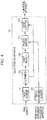
- the microcomputer 135 executes the program 137A thereby functioning as a target tracker 191 in addition to the functional blocks 171 to 179 described above, as shown in Fig. 4 .
- a processing procedure defined in the program 137A and performed by the microcomputer 135 is described in detail below.
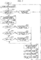
- the processing flow shown in Fig. 5 is different from that shown in Fig. 3 in that the processing flow additionally includes steps S101 and S102.
- similar steps to those in Fig. 3 are denoted by similar step numbers, and a further description thereof is omitted or given in a simplified manner.
- the microcomputer 135 After step S001, the microcomputer 135 performs S003. In a case where it is determined in S003 that it is difficult to transmit all target information T (No in S003), the microcomputer 135 functions as the target tracker 191 and performs a target tracking process in step S101. In the target tracking process, the target tracker 191 tracks, on a time axis, the same object described in time-sequential target information T using current and past (for example, previous) target information T. By tracking the same object in the time-sequential target information T, it becomes possible to enhance the reliability of the target information T regarding the object. In other words, it is possible to achieve a higher possibility that the object of interest actually exists in the surroundings of the vehicle V.
- the target tracker 191 transfers the information representing the existence probability, the number of times the tracking was successful, and the information indicating the level of confidence of the target information T (hereinafter referred to simply as confidence level) based on the result of the tracking process to the priority assigner 175.
- confidence level the level of confidence of the target information T
- step S101 the microcomputer 135 performs steps S005 to S019 described above. Thereafter, the microcomputer 135 functions as the priority assigner 175 and changes the priority for the corresponding target information T based on the confidence level of each object received in the step S101 (step S102).
- step S102 for example, the priority for the target information T with a confidence level higher than a reference value is increased by a fourth predetermined value, and the priority for the target information T with a confidence level equal to or lower than a reference value is reduced by a fifth predetermined value.
- the fourth predetermined value and the fifth predetermined value may be set in a similar manner for the predetermined values described above.
- the microcomputer 135 performs steps S021 to S027 described above.
- the first modification it is possible to transmit target information T, which is necessary in safely driving in the current traffic environment, to the in-vehicle apparatus 7 without missing target information T associated with an object highly likely to actually exist.
- step S101 is performed immediately after step S003.
- step S101 is performed after step S001 and before step S102.
- an object detection apparatus 1B according to the second modification of the embodiment is described.
- the object detection apparatus 1B is different from the object detection apparatus 1 in that not the program 137 but a program 137B is stored in the program memory 131.
- similar elements to those in the object detection apparatus 1 are denoted by similar reference symbols, and a further description thereof is omitted.
- the microcomputer 135 executes the program 137B thereby functioning as an information remover 193 in addition to the functional blocks 171 to 179 described above, as shown in Fig. 6 .
- a processing procedure defined in the program 137B and performed by the microcomputer 135 is described in detail below.
- the processing flow shown in Fig. 7 is different from that shown in Fig. 3 in that the processing flow additionally includes steps S201.
- similar steps to those in Fig. 3 are denoted by similar step numbers, and a further description thereof is omitted or given in a simplified manner.
- the microcomputer 135 functions as the information remover 193 (step S201).
- the information remover 193 classifies the pieces of information selected in step S023 from the target information T such that pieces of information being high in priority are classified in a first group.
- the number of pieces of information in the target information T classified in the first group may be properly determined when the object detection apparatus 1B is designed or developed.
- the information remover 193 further classifies pieces of information in the target information T such that pieces of information that are selected in step S023 but that are not classified in the first group and pieces of information remaining in the target information T without being selected in step S023 are classified in a second group.
- the microcomputer 135 further functions as the information remover 193 and removes predetermined items from the pieces of information in the target information T classified in the second group. For example, to identify the location of an object, a distance and a direction described in target information T have a high relativity, but a relative speed and a signal strength do not have a high relativity. Therefore, the microcomputer 135 removes the relative speed and the signal strength from each piece of information in the target information T classified in the second group. As a result, the number of items included in the pieces of information in the target information T classified in the first group becomes larger than the number of items included in the pieces of information in the target information T belonging to the second group.
- the microcomputer 135 functions as the target outputter 179 and transmits the pieces of information in the target information T selected in step S023 sequentially, for example, in order of priority from high to low, to the data transmission line 9 via the output port 15 (step S025).
- the microcomputer 135 transmits as many pieces as allowed by the data output rate and the output time.
- the predetermined items are removed from the pieces of information in the target information T in the second group, and thus the object detection apparatus 1B is capable of transmitting a larger number of pieces of information in the target information T to the in-vehicle apparatus 7 although the number of items is reduced.
- the sensor 3 it is possible to reduce the number of objects that are not transmitted although they are detected by the sensor 3.
- the object detection apparatus 1B removes information on the relative speed and the signal strength from the pieces of information in the target information T classified in the second group.
- the items removed by the information remover 193 are not limited to these.
- the information remover 193 may change one or more items removed from the pieces of information in the target information T classified in the second group depending on the traffic environment information E acquired in step S007. More specifically, on expressways, objects located in the surroundings of the vehicle V can be supposed to be vehicles. Therefore, in a case where the answer to step S009 is Yes, then in step S201, information on the signal strength is removed from the pieces of information in the target information T belong to the second group. After step S011 or in a case where the answer to step S013 is Yes, information on the signal strength and the relative speed is removed from the pieces of information in the target information T classified in the second group.
- the information remover 193 may divide the pieces of information in the target information T belonging to the second group into n subgroups (1st to nth subgroups), and may output information in the target information T belong to each subgroup to the in-vehicle apparatus 7 at a low rate. More specifically, in step S025 in 1st to nth iterations, pieces of information in the target information T respectively belonging to the 1st to nth subgroups are sequentially output on a subgroup-by-subgroup basis. By performing the process in the above-described manner, it is also possible to prevent the target information T detected by the sensor 3 from being missed.
- the information remover 193 may transmit information such that, of the pieces of information in the current target information T associated with the objects being successfully tracked, items whose values have changed from past values are transmitted regardless of whether the information is in the first group or the second group, and the information remover 193 may remove items whose values have not changed.
- items in the current target information T associated with objects being successfully tracked may be removed if no change from the values described in the past target information T is observed.
- the information remover 193 classifies the pieces of information selected in step S023 from the target information T such that pieces of information being high in priority are classified in a first group, and the information remover 193 further classifies pieces of information in the target information T such that pieces of information that are selected in step S023 but that are not classified in the first group and pieces of information remaining in the target information T without being selected in step S023 are classified in a second group.
- the information remover 193 may classify the pieces of information selected in step S023 from the target information T such that pieces of information being high in priority are classified in a first group, and pieces of information that are selected in step S023 from the target information T but that are not classified in the first group are classified in the second group. The makes it possible to reduce the transmission bandwidth of the data transmission line 9 used by the object detection apparatus 1B.
- the present disclosure can be realized by software, hardware, or software in cooperation with hardware.
- Each functional block used in the description of each embodiment described above can be partly or entirely realized by an LSI such as an integrated circuit, and each process described in each embodiment may be controlled partly or entirely by the same LSI or a combination of LSIs.
- the LSI may be individually formed as chips, or one chip may be formed so as to include a part or all of the functional blocks.
- the LSI may include a data input and output coupled thereto.
- the LSI here may be referred to as an IC, a system LSI, a super LSI, or an ultra LSI depending on a difference in the degree of integration.
- the technique of implementing an integrated circuit is not limited to the LSI and may be realized by using a dedicated circuit, a general-purpose processor, or a special-purpose processor.
- a Field Programmable Gate Array FPGA
- FPGA Field Programmable Gate Array
- the present disclosure can be realized as digital processing or analogue processing.
- the object detection apparatus is capable of detecting a moving object with enhanced reliability and stability, and the object detection apparatus may be applied to a navigation apparatus, an automatic driving control apparatus, or the like.
- an object detection apparatus comprising: an input port that receives information on a plurality of objects in surroundings of a vehicle and information on a traffic environment of the vehicle, the plurality of objects being detected by a sensor installed on the vehicle; a controller that determines, based on the information on the plurality of objects and the information on the traffic environment, priority for each of the plurality of objects and determines first information based on the priority in a case where the total amount of information on the plurality of objects is greater than a determined value, the first information being information on part of the plurality of objects; and an output port that outputs the first information to an in-vehicle apparatus that controls the vehicle.
- the information on the traffic environment is at least one of a navigation apparatus used in the vehicle, a traffic environment recognition apparatus installed on a road on which the vehicle runs, and the sensor.
- the in-vehicle apparatus is at least one of a device that controls running of the vehicle and a device that controls one or more contents displayed on a display apparatus used in the vehicle.
- the output port outputs the first information to the in-vehicle apparatus sequentially in order of priority from high to low.
- information on each object detected by the sensor includes a plurality of items associated with the object
- the output port outputs, to the in-vehicle apparatus, information on the plurality of objects belonging to a first information group and information on the plurality of objects belonging to a second information group being lower in priority than the first information group, the first information group and the second information group being included in the first information, and wherein the number of items included in the first information group is larger than the number of items included in the second information group.
- controller removes one or more items from the second information group based on the information on the traffic environment.
- the output port outputs to the in-vehicle apparatus, information on the plurality of objects belonging to a first information group and information on the plurality of objects belonging to a second information group being lower in priority than the first information group, the first information group and the second information group being included in the first information, and wherein the frequency of outputting the second information group is lower than the frequency of outputting the first information group.
- the controller attempts to repeatedly perform a target tracking process on the plurality of objects based on the information on the plurality of objects received time-sequentially via the input port to determine the priority based on the information on the plurality of objects, the information on the traffic environment, and a result of the target tracking process.
- a ninth aspect which is provided in addition to an eighth aspect, comprising a memory, wherein the controller repeatedly detects second information on a first object selected by the target tracking process on the plurality of objects and repeatedly stores the second information in the memory, the second information including a plurality of second items associated with the first object.
- the controller detects, by comparing the detected second information with the stored second information, one or more differential second items among the plurality of second items; the output port outputs the one or more differential second items to the in-vehicle apparatus.
- an eleventh aspect which is provided in addition to an eighth aspect, comprising a memory, wherein the output port outputs, to the in-vehicle apparatus, information on the plurality of objects belonging to a first information group and information on the plurality of objects belonging to a second information group being lower in priority than the first information group, the first information group and the second information group being included in the first information, wherein the controller repeatedly detects third information on a third object among the second information group selected by the target tracking process on the plurality of objects and repeatedly stores the third information in the memory, the third information including a plurality of third items associated with the third object, and detects, by comparing the third information with the stored third information, one or more differential third items among the plurality of third items, and wherein the output port outputs the one or more differential third items to the in-vehicle apparatus.
- a non-transitory computer-readable storage medium storing a program that causes a computer to execute a process comprising: receiving information on a plurality of objects in surroundings of a vehicle and information on a traffic environment of the vehicle, the plurality of objects being detected by a sensor installed on the vehicle; determining, based on the information on the plurality of objects and the information on the traffic environment, priority for each of the plurality of objects and determining first information based on the priority in a case where the total amount of information on the plurality of objects is greater than a determined value, the first information being information on part of the plurality of objects; and outputting the first information to an in-vehicle apparatus that controls the vehicle.
Abstract
Description
- The present disclosure relates to an object detection apparatus that outputs, to an in-vehicle apparatus, information on an object detected by a sensor installed on a vehicle, and a storage medium.
- A type of an object detection apparatus is disclosed, for example, in Japanese Unexamined Patent Application Publication
2007-232412 - In the known object detection apparatus, the priority of objects to be detected is determined based on the reflection intensity. However, objects to be detected for a vehicle may be different depending on a traffic environment.
- One non-limiting and exemplary embodiment facilitates providing an object detection apparatus, and a storage medium capable of outputting information on an object depending on a traffic environment.
- In one general aspect, the techniques disclosed here feature an object detection apparatus including an input port that receives information on a plurality of objects in surroundings of a vehicle and information on a traffic environment of the vehicle, the plurality of objects being detected by a sensor installed on the vehicle, a controller that determines, based on the information on the plurality of objects and the information on the traffic environment, priority for each of the plurality of objects and determines first information based on the priority in a case where the total amount of information on the plurality of objects is greater than a determined value, the first information being information on part of the plurality of objects, and an output port that outputs the first information to an in-vehicle apparatus that controls the vehicle.
- According to the present disclosure, it is possible to facilitate providing an object detection apparatus and a storage medium, capable of outputting information on an object depending on a traffic environment.
- It should be noted that general or specific embodiments may be implemented as a system, a method, an integrated circuit, a computer program, a storage medium, or any selective combination thereof.
- Additional benefits and advantages of the disclosed embodiments will become apparent from the specification and drawings. The benefits and/or advantages may be individually obtained by the various embodiments and features of the specification and drawings, which need not all be provided in order to obtain one or more of such benefits and/or advantages.
-
-
Fig. 1 illustrates a hardware configuration of an object detection apparatus according to the disclosure and a configuration of a peripheral configuration; -
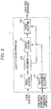
Fig. 2 illustrates functional blocks of an object detection apparatus according to a first embodiment; -
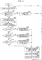
Fig. 3 illustrates a flow of a process performed by the object detection apparatus shown inFig. 2 ; -
Fig. 4 illustrates functional blocks of an object detection apparatus according to a first modification; -
Fig. 5 illustrates a flow of a process performed by the object detection apparatus shown inFig. 4 ; -
Fig. 6 illustrates functional blocks of an object detection apparatus according to a second modification; and -
Fig. 7 illustrates a flow of a process performed by the object detection apparatus shown inFig. 6 . - Referring to drawings, the present disclosure is described in further detail below with reference to embodiments of
object detection apparatuses 1, 1A, and 1B, programs 137, 137A, and 137B, and a storage medium storing the program 137, 137A, or 137B. - First, an object detection apparatus 1 according to an embodiment of the present disclosure is described.
- In
Fig. 1 , a vehicle V includes, as apparatuses installed therein, in addition to the object detection apparatus 1 described above, asensor 3, a traffic environment transmission apparatus 5, and an in-vehicle apparatus 7. In the present disclosure, it is possible to perform data transmission via a data transmission line 9, using a particular data transmission method, between the object detection apparatus 1 and each of other apparatuses including thesensor 3, the traffic environment transmission apparatus 5, and the in-vehicle apparatus 7. Examples of the data transmission method include Controller Area Network (CAN), Ethernet (registered trademark), etc. - First, the
sensor 3 and the traffic environment transmission apparatus 5 are described. Thesensor 3 is, for example, a millimeter wave radar, and is installed, for example, near the front end of the vehicle V. For example, thesensor 3 periodically transmits a radar signal (for example, a radio wave in a millimeter wave band) within a measurable range (in other words, in a visible range). When thesensor 3 receives, via its receiving antenna, a return signal which is a radar signal output and reflected back from an object (target object), thesensor 3 executes a known target recognition algorithm. As a result, a direction, a distance, a relative speed, a return signal strength, and/or the like of an object (typically a moving object) existing in surroundings of the vehicle V are detected time-sequentially. Thesensor 3 time sequentially transmits target information T associated with each object existing in the surroundings of the vehicle V to the object detection apparatus 1 via the data transmission line 9. In the present disclosure, the target information T includes items such as the direction, the distance, the relative speed, and/or the like of the object with reference to the vehicle V (or the sensor 3). - The traffic environment transmission apparatus 5 is, for example, a navigation apparatus. For example, the traffic environment transmission apparatus 5 is capable of identifying a current location of the vehicle V (more specifically, the current position of the sensor 3) and capable of acquiring network data representing a road distribution expressed typically using links and nodes from a local storage device (not illustrated) or a remote server. Each node represents a feature point (an intersection or a bending point) on a road. Each link represents a road between each of nodes. Each link is assigned various kinds of information on a road, such as a road type or the like. Examples of road types include an expressway, a general road, a road close to an intersection, and the like.
- The traffic environment transmission apparatus 5 identifies, in response to a request from the object detection apparatus 1, a road on which the vehicle V is currently running, and acquires traffic environment information E including a type of the identified road from network data. The traffic environment transmission apparatus 5 transmits the acquired traffic environment information E to the object detection apparatus 1 via the data transmission line 9.
- The object detection apparatus 1 is disposed, for example, in an Electronic Control Unit (ECU), and includes an
input port 11, acontroller 13, and anoutput port 15. - The
input port 11 is an input interface according to the data transmission method described above. Theinput port 11 receives target information T from thesensor 3 and traffic environment information E from the traffic environment transmission apparatus 5. Furthermore, under the control of thecontroller 13, theinput port 11 transfers the received target information T and the traffic environment information E to amain memory 133 of thecontroller 13. - The
controller 13 includes, for example, aprogram memory 131, themain memory 133, and amicrocomputer 135. - The
program memory 131 is, for example, a non-transitory memory such as EEPROM. In theprogram memory 131, a program 137 describing a processing procedure (described later with reference toFig. 3 ) is stored in advance. - The
main memory 133 is, for example, a semiconductor memory such as SRAM. - The
microcomputer 135 executes the program 137 using themain memory 133 or the like as a work area. Basically, themicrocomputer 135 transmits all received target information T to the in-vehicle apparatus 7 via the data transmission line 9. However, in a case where it is impossible to transmit all received target information T, themicrocomputer 135 selects target information with high priority from the received target information T, and transmits the selected target information with high priority to the in-vehicle apparatus 7 via the data transmission line 9. - The
output port 15 is an output interface according to the data transmission method, and transmits target information T to the in-vehicle apparatus 7 via the data transmission line 9 each time the target information T to be transmitted is determined by themicrocomputer 135. - The in-vehicle apparatus 7 is an apparatus such as a display apparatus, an automatic braking apparatus, or the like installed in the vehicle V, and performs a particular process based on a detection result R received from the
output port 15. 1-2. Process performed bycontroller 13 - In the
controller 13, as described above, themicrocomputer 135 executes the program 137 thereby functioning as atarget acquirer 171, adeterminer 173, apriority assigner 175, atraffic environment acquirer 177 and atarget outputter 179, as illustrated inFig. 2 . Next, referring toFig. 1 to Fig. 3 , an operation by the object detection apparatus 1 (for example, a processing procedure of themicrocomputer 135 defined in the program 137) is described below. - The target information T transmitted time-sequentially from the
sensor 3 is received by theinput port 11. Fist, themicrocomputer 135 functions as thetarget acquirer 171 and transfers the received target information T to themain memory 133. As a result, thecontroller 13 acquires the target information T (step S001 inFig. 3 ). - After step S001, the
microcomputer 135 functions as thedeterminer 173, and determines whether it is possible to transmit all target information T acquired in step S001 to the in-vehicle apparatus 7 (step S003). More specifically, the transmission bandwidth usable in the data transmission from the object detection apparatus 1 to the in-vehicle apparatus 7 is limited to a predetermined fixed value. Furthermore, the transmission from the target information T to the in-vehicle apparatus 7 generally needs to be performed in real time. Thus, in step S003, it is determined whether it is possible to transmit all target information T received by the object detection apparatus 1 to the in-vehicle apparatus 7 using a usable transmission bandwidth within a predetermined period of time. In other words, it is determined whether the data output rate (transmission bandwidth) [bits/sec] at theoutput port 15 × output time (predetermine time period) [sec] is larger than the total amount of data [bits] of the acquired target information T. - In a case where it is determined in step S003 (by the determiner 173) that it is possible to transmit all target information T (Yes in step S003), then the
microcomputer 135 functions as thetarget outputter 179 and transmits all target information T acquired in step S001 to the in-vehicle apparatus 7 (step S027). After step S027, themicrocomputer 135 returns the process to step S001, in which themicrocomputer 135 performs a process shown inFig. 3 on the target information T that theinput port 11 newly receives from thesensor 3 via the data transmission line 9. - On the other hand, in a case where it is determined in step S003 (by the determiner 173) that it is impossible to transmit all target information T (No in step S003), the
microcomputer 135 functions as thepriority assigner 175 and determines an initial priority for each piece of information included in the whole target information T acquired in step S001 and sorts the pieces of information in the target information T in order of priority from high to low (step S005). In this step S005, for example, the closer the distance between the vehicle V (or the sensor 3) and the object described in a piece of information in the target information T, the higher the priority assigned to the piece in the target information T. - Next, the
microcomputer 135 functions as thetraffic environment acquirer 177 and acquires traffic environment information E from the traffic environment transmission apparatus 5. In the present disclosure, the traffic environment information E represents a traffic environment in the surroundings of the vehicle V, and more specifically the traffic environment information E includes information indicating a type of a road on which the vehicle V is currently running (hereinafter referred to as a road type). Examples of road types include an expressway, a general road, a road close to intersection, and the like. The traffic environment information E is received by theinput port 11. Themicrocomputer 135 transfers the received traffic environment information E to themain memory 133. As a result, thecontroller 13 acquires the traffic environment information E (step S007). - Next, the
microcomputer 135 functions as thepriority assigner 175 and determines whether the road type described in the traffic environment information E is the expressway, the road close to intersection, or the general road (steps S009, S011, and S013). - In a case where the road type is the expressway, the
microcomputer 135 advances the processing flow from step S009 to step S015, in which themicrocomputer 135 changes the priority of pieces of information included in the target information T currently stored in themain memory 133 such that the priority of a piece of information associated with an oncoming vehicle is reduced by a first predetermined value (step S015). This process is performed because expressways each have a center divider and thus oncoming vehicles do not have significant influences on running or driving of the vehicle V. The determination as to whether the target information T indicates an oncoming vehicle or not may be performed based a relative speed and a direction described in the target information T. The first predetermined value may be properly determined when the object detection apparatus 1 is designed or developed. In a case where the road type is not the expressway, themicrocomputer 135 advances the processing flow from step S009 to step S011. - In a case where the road type is the road close to intersection, the
microcomputer 135 advances the processing flow from step S011 to step S017, in which themicrocomputer 135 changes the priority of pieces of information included in the target information T currently stored in themain memory 133 such that the priority of a piece of information associated with an oncoming vehicle is increased by a second predetermined value (step S017). This process is performed because, on the road close to intersection, oncoming vehicles have significant influences on running or driving of the vehicle V. More specifically, when the vehicle V runs straight or makes a right turn at an intersection, the running or driving of the vehicle V may be influenced by an oncoming vehicle running straight or making a right turn. The determination as to whether a piece of information in the target information T indicates an oncoming vehicle or not may be performed based a relative speed and a direction described in the target information T. The second predetermined value may be properly determined when the object detection apparatus 1 is designed or developed. In a case where the road type is not the road close to intersection, themicrocomputer 135 advances the processing flow from step S011 to step S013. - In a case where the road type is a general road, the
microcomputer 135 advances the processing flow from step S013 to step S019, in which themicrocomputer 135 changes the priority of pieces of information included in the target information T currently stored in themain memory 133 such that the priority of a piece of information associated with a vehicle approaching the vehicle V at a high speed is increased by a third predetermined value (step S019). This process is performed because the running and the driving of the vehicle V are influenced by moving objects (mainly vehicles) located near the vehicle V and approaching the vehicle V at a high speed. In the present disclosure, the initial priority for each piece of information in the target information T is determined, in step S005, depending on the distance between the vehicle V and the object, and thus, in step S019, the priority is increased for a vehicle approaching the vehicle V at a high speed. The determination as to whether a piece of information in the target information T indicates a vehicle approaching the vehicle V at a high speed may be performed based a relative speed and a direction described in the target information T. The third predetermined value may be properly determined when the object detection apparatus 1 is designed or developed. - After steps S015, S017, and S019 described above, the
microcomputer 135 functions as thetarget outputter 179 and sorts the pieces of information in the target information T currently stored in themain memory 133 in order of priority from high to low (step S021). - After step S021 or in a case where the answer to step S013 is No, the
microcomputer 135 functions as thetarget outputter 179 and selects, from the target information T currently stored in themain memory 133, pieces of information that the object detection apparatus 1 can output to the in-vehicle apparatus 7 within the predetermined time period described above based on the priority assigned to the pieces of information (step S023). - The
microcomputer 135 further functions as thetarget outputter 179 and sequentially transmits the pieces of information selected in step S023 in the target information T, for example, in order of priority from high to low, to the data transmission line 9 via the output port 15 (step S025). The transmitted pieces of information of the target information T are received by the in-vehicle apparatus 7 via the data transmission line 9. In a case where the in-vehicle apparatus 7 is a display apparatus, an object existing in the surroundings of the vehicle V is displayed based on the received target information T to call attention of a driver of the vehicle V. If the in-vehicle apparatus 7 is an automatic braking apparatus, braking of the vehicle V is controlled, as required, to reduce the speed of the vehicle V or stop the vehicle V based on the received target information T. - After step S025, the
microcomputer 135 returns the processing flow to step S001, in which themicrocomputer 135 performs a process shown inFig. 3 on the target information T that theinput port 11 newly receives from thesensor 3 via the data transmission line 9. - In the object detection apparatus 1, as described above, the
input port 11 receives, from thesensor 3, the target information T including pieces of information associated with respective objects existing in the surroundings of the vehicle V, and also receives traffic environment information E representing the traffic environment in the surroundings of the vehicle V from the traffic environment transmission apparatus 5. In thecontroller 13, thetarget acquirer 171 stores the target information T received via theinput port 11 in themain memory 133. Thetraffic environment acquirer 177 stores the traffic environment information E received via theinput port 11 in themain memory 133. - The
priority assigner 175 determines the priority for each of a plurality of objects (described in the target information T) based on the target information T and the traffic environment information E taking into account the influence of the current traffic environment on the running of the vehicle V. In a case where the total amount of data of the target information T in themain memory 133 is larger than the predetermined value, thetarget outputter 179 selects pieces of information from the target information T stored in themain memory 133 according to the priority determined by thepriority assigner 175 and transmits the selected pieces of information to the data transmission line 9 toward the in-vehicle apparatus 7. Note that thepriority assigner 175 retains the remaining part of the target information T of objects in themain memory 133. - Thus, it is possible to provide the object detection apparatus 1 and the program 137 capable of limiting the target information T on objects to be output depending on the traffic environment. In particular, the object detection apparatus 1 according to the present disclosure limits the target information T output to the data transmission line 9 to pieces of information associated with objects being highly likely to have an influence on the running of the vehicle V in the current traffic environment. This makes it possible to transmit the target information T to the in-vehicle apparatus 7 without missing part of the target information T used in safely driving the vehicle V in the current traffic environment.
- Furthermore, in the present object detection apparatus 1, in step S025, pieces of information included in the target information T are transmitted sequentially in order of priority from high to low to the data transmission line 9, and thus it is possible for the in-vehicle apparatus 7 to quickly receive part of the target information T on objects having a possibility of exerting a significant influence on driving the vehicle V. Therefore, the object detection apparatus 1 is capable of having a large contribution to safe driving of the vehicle V.
- In the embodiment described above, it is assumed by way of example, for convenience of explanation, that the traffic environment information E includes information on a road type. However, the traffic environment information E is not limited to the information on the road type, but the traffic environment information E may be any information as long as the information has an influence on the running of the vehicle V or the priority of objects. For example, the traffic environment information E may be information representing a road width, a line shape, a slope, a crossing cant, paving of road, a pedestrian-vehicle separation, or a center division, or a combination of two or more of these items. The running of the vehicle V and/or the priority of objects are basically dependent on the road characteristics such as those described above, but are also influenced by presence/absence of buildings in the surroundings, weather conditions, or the like. In view of this fact, the traffic environment information E may include information about buildings close to a road on which the vehicle V is currently running, and/or information about a current weather condition.
-
Fig. 3 also illustrates a processing procedure performed in a case where the traffic environment information E includes information indicating a road type such as an expressway, a road close to intersection, or a general road. Note that the processing procedure inFig. 3 may be properly defined depending on what kind of information is included in the traffic environment information E. - In the embodiment described above, in step S005, the smaller the distance between the vehicle V and an object, the higher the priority assigned to the object. However, the initial priority may be assigned based on another criterion. For example, the higher the running speed of the vehicle V and an object, the higher the priority assigned to the object.
- In the embodiment described above, it is assumed by way of example that the traffic environment transmission apparatus 5 is a navigation apparatus. However, the traffic environment transmission apparatus 5 is not limited to the navigation apparatus, but the traffic environment transmission apparatus 5 may be an in-vehicle apparatus capable of performing a road-to-vehicle communication with an apparatus installed on a side of a road on which the vehicle V is running and acquiring traffic environment information E such as that described above. The
sensor 3 may also be capable of acquiring part of the traffic environment information E, and thus the traffic environment transmission apparatus 5 may be thesensor 3. - In the embodiment described above, it is assumed by way of example that the
sensor 3 is a millimeter wave radar. However, thesensor 3 is not limited to the millimeter wave radar but thesensor 3 may be, for example, a laser radar, a camera, or the like. Thesensor 3 may be a combination of two or more of the millimeter wave radar, the laser radar, and the camera. - In the embodiment described above, in view of the transmission bandwidth of the data transmission line 9, the determination in step S003 as to whether the target information T can be transmitted or not is performed by determining whether the data output rate × the output time is larger than the total amount of data of the target information T. However, the method of determining whether all target information T can be transmitted is not limited to the example described above. For example, the determination may be performed based on the viewability of the display apparatus employed as the in-vehicle apparatus 7. In this case, when it is determined in step S003 that the total number of objects described in the target information T is larger than a predetermined value, steps S005 to S025 may be performed. By performing the process in this manner, it becomes possible to limit the number of objects displayed at the same time on the display apparatus, which makes it possible for a driver to easily recognize a plurality of objects existing in the surroundings of the vehicle V.
- In the embodiment described above, it is assumed by way of example that the program 137 is stored in the
program memory 131. However, the storage in which the program 137 is stored is not limited to theprogram memory 131. For example, the program 137 may be stored in a computer-readable storage medium (for example, a DVD or the like). Alternatively, the program 137 may be stored in a server apparatus, and the program 137 may be downloaded to various terminal apparatuses (for example, a desktop personal computer, a smartphone, a tablet terminal, or the like). This also holds for programs 137A and 137B described later. - Next, a first modification of the object detection apparatus 1 is described below.
- First, an
object detection apparatus 1A according to the first modification of the embodiment is described. InFig. 1 , theobject detection apparatus 1A is different from the object detection apparatus 1 in that not the program 137 but a program 137A is stored in theprogram memory 131. In theobject detection apparatus 1A, similar elements to those in the object detection apparatus 1 are denoted by similar reference symbols, and a further description thereof is omitted. - In the
control unit 13, themicrocomputer 135 executes the program 137A thereby functioning as atarget tracker 191 in addition to thefunctional blocks 171 to 179 described above, as shown inFig. 4 . Next, referring toFig. 5 , a processing procedure defined in the program 137A and performed by themicrocomputer 135 is described in detail below. The processing flow shown inFig. 5 is different from that shown inFig. 3 in that the processing flow additionally includes steps S101 and S102. InFig. 5 , similar steps to those inFig. 3 are denoted by similar step numbers, and a further description thereof is omitted or given in a simplified manner. - After step S001, the
microcomputer 135 performs S003. In a case where it is determined in S003 that it is difficult to transmit all target information T (No in S003), themicrocomputer 135 functions as thetarget tracker 191 and performs a target tracking process in step S101. In the target tracking process, thetarget tracker 191 tracks, on a time axis, the same object described in time-sequential target information T using current and past (for example, previous) target information T. By tracking the same object in the time-sequential target information T, it becomes possible to enhance the reliability of the target information T regarding the object. In other words, it is possible to achieve a higher possibility that the object of interest actually exists in the surroundings of the vehicle V. Furthermore, thetarget tracker 191 transfers the information representing the existence probability, the number of times the tracking was successful, and the information indicating the level of confidence of the target information T (hereinafter referred to simply as confidence level) based on the result of the tracking process to thepriority assigner 175. Thus the process in step S101 is completed. - In the first modification, after step S101 is completed, the
microcomputer 135 performs steps S005 to S019 described above. Thereafter, themicrocomputer 135 functions as thepriority assigner 175 and changes the priority for the corresponding target information T based on the confidence level of each object received in the step S101 (step S102). In step S102, for example, the priority for the target information T with a confidence level higher than a reference value is increased by a fourth predetermined value, and the priority for the target information T with a confidence level equal to or lower than a reference value is reduced by a fifth predetermined value. The fourth predetermined value and the fifth predetermined value may be set in a similar manner for the predetermined values described above. Thereafter, themicrocomputer 135 performs steps S021 to S027 described above. - According to the first modification, it is possible to transmit target information T, which is necessary in safely driving in the current traffic environment, to the in-vehicle apparatus 7 without missing target information T associated with an object highly likely to actually exist.
- In the first modification, step S101 is performed immediately after step S003. However, there is no restriction on the timing of performing step S101 as long as step S101 is performed after step S001 and before step S102.
- Next, a second modification of the object detection apparatus 1 is described below.
- Next, an object detection apparatus 1B according to the second modification of the embodiment is described. In
Fig. 1 , the object detection apparatus 1B is different from the object detection apparatus 1 in that not the program 137 but a program 137B is stored in theprogram memory 131. In the object detection apparatus 1B, similar elements to those in the object detection apparatus 1 are denoted by similar reference symbols, and a further description thereof is omitted. - In the
control unit 13, themicrocomputer 135 executes the program 137B thereby functioning as aninformation remover 193 in addition to thefunctional blocks 171 to 179 described above, as shown inFig. 6 . Next, referring toFig. 7 , a processing procedure defined in the program 137B and performed by themicrocomputer 135 is described in detail below. The processing flow shown inFig. 7 is different from that shown inFig. 3 in that the processing flow additionally includes steps S201. InFig. 7 , similar steps to those inFig. 3 are denoted by similar step numbers, and a further description thereof is omitted or given in a simplified manner. - After steps S001 to S023, the
microcomputer 135 functions as the information remover 193 (step S201). In the second modification, first, theinformation remover 193 classifies the pieces of information selected in step S023 from the target information T such that pieces of information being high in priority are classified in a first group. The number of pieces of information in the target information T classified in the first group may be properly determined when the object detection apparatus 1B is designed or developed. The information remover 193 further classifies pieces of information in the target information T such that pieces of information that are selected in step S023 but that are not classified in the first group and pieces of information remaining in the target information T without being selected in step S023 are classified in a second group. - The
microcomputer 135 further functions as the information remover 193 and removes predetermined items from the pieces of information in the target information T classified in the second group. For example, to identify the location of an object, a distance and a direction described in target information T have a high relativity, but a relative speed and a signal strength do not have a high relativity. Therefore, themicrocomputer 135 removes the relative speed and the signal strength from each piece of information in the target information T classified in the second group. As a result, the number of items included in the pieces of information in the target information T classified in the first group becomes larger than the number of items included in the pieces of information in the target information T belonging to the second group. - Next, the
microcomputer 135 functions as thetarget outputter 179 and transmits the pieces of information in the target information T selected in step S023 sequentially, for example, in order of priority from high to low, to the data transmission line 9 via the output port 15 (step S025). In this process, as for the pieces of information in the target information T classified in the first group, all items thereof are transmitted. On the other hand, as for the pieces of information in the target information T in the second group (that is, information in terms of the distance and the direction), themicrocomputer 135 transmits as many pieces as allowed by the data output rate and the output time. - According to the second modification, the predetermined items are removed from the pieces of information in the target information T in the second group, and thus the object detection apparatus 1B is capable of transmitting a larger number of pieces of information in the target information T to the in-vehicle apparatus 7 although the number of items is reduced. Thus, it is possible to reduce the number of objects that are not transmitted although they are detected by the
sensor 3. - In the example described above, the object detection apparatus 1B removes information on the relative speed and the signal strength from the pieces of information in the target information T classified in the second group. However, the items removed by the
information remover 193 are not limited to these. For example, theinformation remover 193 may change one or more items removed from the pieces of information in the target information T classified in the second group depending on the traffic environment information E acquired in step S007. More specifically, on expressways, objects located in the surroundings of the vehicle V can be supposed to be vehicles. Therefore, in a case where the answer to step S009 is Yes, then in step S201, information on the signal strength is removed from the pieces of information in the target information T belong to the second group. After step S011 or in a case where the answer to step S013 is Yes, information on the signal strength and the relative speed is removed from the pieces of information in the target information T classified in the second group. - In a still alternative example, the
information remover 193 may divide the pieces of information in the target information T belonging to the second group into n subgroups (1st to nth subgroups), and may output information in the target information T belong to each subgroup to the in-vehicle apparatus 7 at a low rate. More specifically, in step S025 in 1st to nth iterations, pieces of information in the target information T respectively belonging to the 1st to nth subgroups are sequentially output on a subgroup-by-subgroup basis. By performing the process in the above-described manner, it is also possible to prevent the target information T detected by thesensor 3 from being missed. - In a still alternative example, in a case where the object detection apparatus 1B includes the
target tracker 191 shown inFig. 4 , if thetarget tracker 191 is capable of successfully tracking the same object in a time series of target information T, theinformation remover 193 may transmit information such that, of the pieces of information in the current target information T associated with the objects being successfully tracked, items whose values have changed from past values are transmitted regardless of whether the information is in the first group or the second group, and theinformation remover 193 may remove items whose values have not changed. In a still alternative example, as for the second group, items in the current target information T associated with objects being successfully tracked may be removed if no change from the values described in the past target information T is observed. - In the second modification described above, from the point of view of reducing the number of objects that are not transmitted although they are detected by the
sensor 3, theinformation remover 193 classifies the pieces of information selected in step S023 from the target information T such that pieces of information being high in priority are classified in a first group, and the information remover 193 further classifies pieces of information in the target information T such that pieces of information that are selected in step S023 but that are not classified in the first group and pieces of information remaining in the target information T without being selected in step S023 are classified in a second group. However, alternatively, theinformation remover 193 may classify the pieces of information selected in step S023 from the target information T such that pieces of information being high in priority are classified in a first group, and pieces of information that are selected in step S023 from the target information T but that are not classified in the first group are classified in the second group. The makes it possible to reduce the transmission bandwidth of the data transmission line 9 used by the object detection apparatus 1B. - The embodiments and modifications described above are merely examples of implementations of the present disclosure, and it is to be understood that these examples do not limit the technical scope of the present disclosure. That is, it is possible to realize the present disclosure in various forms without departing from the scope or the main features of the present disclosure.
- The present disclosure can be realized by software, hardware, or software in cooperation with hardware.
- Each functional block used in the description of each embodiment described above can be partly or entirely realized by an LSI such as an integrated circuit, and each process described in each embodiment may be controlled partly or entirely by the same LSI or a combination of LSIs. The LSI may be individually formed as chips, or one chip may be formed so as to include a part or all of the functional blocks. The LSI may include a data input and output coupled thereto. The LSI here may be referred to as an IC, a system LSI, a super LSI, or an ultra LSI depending on a difference in the degree of integration.
- However, the technique of implementing an integrated circuit is not limited to the LSI and may be realized by using a dedicated circuit, a general-purpose processor, or a special-purpose processor. In addition, a Field Programmable Gate Array (FPGA) that can be programmed after the manufacture of the LSI or a reconfigurable processor in which the connections and the settings of circuit cells disposed inside the LSI can be reconfigured may be used. The present disclosure can be realized as digital processing or analogue processing.
- If future integrated circuit technology replaces LSIs as a result of the advancement of semiconductor technology or other derivative technology, the functional blocks could be integrated using the future integrated circuit technology. Biotechnology can also be applied.
- The object detection apparatus according to the present disclosure is capable of detecting a moving object with enhanced reliability and stability, and the object detection apparatus may be applied to a navigation apparatus, an automatic driving control apparatus, or the like.
- According to the first aspect, an object detection apparatus is provided comprising: an input port that receives information on a plurality of objects in surroundings of a vehicle and information on a traffic environment of the vehicle, the plurality of objects being detected by a sensor installed on the vehicle; a controller that determines, based on the information on the plurality of objects and the information on the traffic environment, priority for each of the plurality of objects and determines first information based on the priority in a case where the total amount of information on the plurality of objects is greater than a determined value, the first information being information on part of the plurality of objects; and an output port that outputs the first information to an in-vehicle apparatus that controls the vehicle.
- According to a second aspect, which is provided in addition to the first aspect, wherein the information on the traffic environment is at least one of a navigation apparatus used in the vehicle, a traffic environment recognition apparatus installed on a road on which the vehicle runs, and the sensor.
- According to a third aspect, which is provided in addition to the first aspect, wherein the in-vehicle apparatus is at least one of a device that controls running of the vehicle and a device that controls one or more contents displayed on a display apparatus used in the vehicle.
- According to a fourth aspect, which is provided in addition to the first aspect, wherein the output port outputs the first information to the in-vehicle apparatus sequentially in order of priority from high to low.
- According to a fifth aspect, which is provided in addition to the first aspect, wherein information on each object detected by the sensor includes a plurality of items associated with the object, wherein the output port outputs, to the in-vehicle apparatus, information on the plurality of objects belonging to a first information group and information on the plurality of objects belonging to a second information group being lower in priority than the first information group, the first information group and the second information group being included in the first information, and wherein the number of items included in the first information group is larger than the number of items included in the second information group.
- According to a sixth aspect, which is provided in addition to the fifth aspect, wherein the controller removes one or more items from the second information group based on the information on the traffic environment.
- According to a seventh aspect, which is provided in addition to the first aspect, wherein the output port outputs to the in-vehicle apparatus, information on the plurality of objects belonging to a first information group and information on the plurality of objects belonging to a second information group being lower in priority than the first information group, the first information group and the second information group being included in the first information, and wherein the frequency of outputting the second information group is lower than the frequency of outputting the first information group.
- According to an eighth aspect, which is provided in addition to the first aspect, wherein the controller attempts to repeatedly perform a target tracking process on the plurality of objects based on the information on the plurality of objects received time-sequentially via the input port to determine the priority based on the information on the plurality of objects, the information on the traffic environment, and a result of the target tracking process.
- According to a ninth aspect, which is provided in addition to an eighth aspect, comprising a memory, wherein the controller repeatedly detects second information on a first object selected by the target tracking process on the plurality of objects and repeatedly stores the second information in the memory, the second information including a plurality of second items associated with the first object.
- According to a tenth aspect, which is provided in addition to the ninth aspect, wherein the controller detects, by comparing the detected second information with the stored second information, one or more differential second items among the plurality of second items; the output port outputs the one or more differential second items to the in-vehicle apparatus.
- According to an eleventh aspect, which is provided in addition to an eighth aspect, comprising a memory, wherein the output port outputs, to the in-vehicle apparatus, information on the plurality of objects belonging to a first information group and information on the plurality of objects belonging to a second information group being lower in priority than the first information group, the first information group and the second information group being included in the first information, wherein the controller repeatedly detects third information on a third object among the second information group selected by the target tracking process on the plurality of objects and repeatedly stores the third information in the memory, the third information including a plurality of third items associated with the third object, and detects, by comparing the third information with the stored third information, one or more differential third items among the plurality of third items, and wherein the output port outputs the one or more differential third items to the in-vehicle apparatus.
- According to a twelfth aspect, a non-transitory computer-readable storage medium storing a program that causes a computer to execute a process is provided comprising: receiving information on a plurality of objects in surroundings of a vehicle and information on a traffic environment of the vehicle, the plurality of objects being detected by a sensor installed on the vehicle; determining, based on the information on the plurality of objects and the information on the traffic environment, priority for each of the plurality of objects and determining first information based on the priority in a case where the total amount of information on the plurality of objects is greater than a determined value, the first information being information on part of the plurality of objects; and outputting the first information to an in-vehicle apparatus that controls the vehicle.
Claims (17)
- An object detection apparatus (1) comprising:an input port (11) adapted to receives target information (T) including pieces of information associated with respective objects of a plurality of objects in surroundings of a vehicle (V) and to receive traffic information (E) representing a traffic environment in surroundings of the vehicle, the target information (T) of the plurality of objects being detected a sensor (3);a memory (133) adapted to store the received target information (T) and the received traffic information (E);in case where the total amount of data of the target information (T) is greater than a determined value,a controller (13) adapted to determine, based on the target information (T) and the traffic information (E), a priority for each of the plurality of objects,the controller (13) adapted to output selected pieces of information to an in-vehicle apparatus (7) that controls the vehicle (V),wherein the total amount of data is an amount of data of the target information (T),wherein information on each object detected by the sensor includes a plurality of items associated with the object,wherein an output port (15) is adapted to output, to the in-vehicle apparatus, pieces of information belonging to a first group and pieces of information belonging to a second group, andwherein the number of items included in the first group is larger than the number of items included in the second group.
- The object detection apparatus (1) according to claim 1,
wherein, if a road type described in the traffic information (E) is an expressway, a priority for each of the plurality of objects including direction information indicating oncoming direction is reduced compared to a priority for each of the plurality of objects including direction information not indicating oncoming direction. - The object detection apparatus (1) according to claim 1,
wherein, if a road type described in the traffic information (E) is an intersection, a priority for each of the plurality of objects including direction information indicating oncoming direction is increased compared to a priority for each of the plurality of objects including direction information not indicating oncoming direction. - The object detection apparatus (1) according to claim 1,
wherein, if a road type described in the traffic information (E) is a general road, a priority for each of the plurality of objects including direction information indicating oncoming direction and relative speed information indicating high speed is increased compared to a priority for each of the plurality of objects including direction information not indicating oncoming direction or relative speed information not indicating high speed. - The object detection apparatus according to Claim 1, wherein the traffic information (E) is at least one of a navigation apparatus used in the vehicle, a traffic environment recognition apparatus installed on a road on which the vehicle runs, and the sensor.
- The object detection apparatus according to Claim 1, wherein the in-vehicle apparatus (7) is at least one of a device that controls running of the vehicle and a device that controls one or more contents displayed on a display apparatus used in the vehicle.
- The object detection apparatus according to Claim 1, wherein the output port (15) is adapted to output the pieces of information to the in-vehicle apparatus sequentially in order of priority from high to low.
- The object detection apparatus according to Claim 1, wherein the controller is adapted to remove one or more items from the second group based on the traffic information.
- The object detection apparatus according to Claim 1,
wherein the output port is adapted to output to the in-vehicle apparatus, target information belonging to a first group and target information belonging to a second group being lower in priority than the first group, the first group and the second group being included in the pieces of information, and
wherein the frequency of outputting the second group is lower than the frequency of outputting the first group. - The object detection apparatus according to Claim 1, wherein the controller is adapted to attempt to repeatedly perform a target tracking process on the plurality of objects based on the target information (T) received time-sequentially via the input port to determine the priority based on the target information, the traffic information, and a result of the target tracking process.
- The object detection apparatus according to Claim 10,
wherein the controller is adapted to repeatedly detect second information on a first object selected by the target tracking process on the plurality of objects and to repeatedly store the second information in the memory (133), the second information including a plurality of second items associated with the first object;
optionally wherein the controller is adapted to detect, by comparing the detected second information with the stored second information, one or more differential second items among the plurality of second items and
the output port is adapted to output the one or more differential second items to the in-vehicle apparatus. - The object detection apparatus according to Claim 10,
wherein the controller is adapted to repeatedly detect third information on a third object among the second group selected by the target tracking process on the plurality of objects and to repeatedly store the third information in the memory (133), the third information including a plurality of third items associated with the third object, and detects, by comparing the third information with the stored third information, one or more differential third items among the plurality of third items, and
wherein the output port is adapted to output the one or more differential third items to the in-vehicle apparatus. - The object detection apparatus (1) according to any one of Claims 1 to 12,
wherein the target information (T) includes at least one of direction information, distance information, and relative speed information of the plurality of objects with reference to the vehicle (V). - The object detection apparatus (1) according to any one of Claims 1 to 13,
wherein the traffic information (E) includes at least one of information indicating a type of a road on which the vehicle (V) is travelling, information indicating a building adjacent to the road on which the vehicle (V) is travelling, and information indicating a current weather condition. - The object detection apparatus according to Claim 1, wherein the memory is adapted to retain the remaining part of the target information (T).
- The object detection apparatus according to Claim 1, wherein the second group being lower in priority than the first group.
- A computer program comprising instructions which, when the program is executed
by a computer, cause the computer to carry out the steps of:receiving target information (T) including pieces of information associated with respective objects of a plurality of objects in surroundings of a vehicle (V);receiving traffic information (E) representing a traffic environment in surroundings of the vehicle, the target information (T) of the plurality of objects being detected by a sensor (3);storing the received target information (T) and the received traffic information (E);in case where the total amount of data of the target information (T) is greater than a determined value,determining, based on the target information (T) and the traffic information (E), a priority for each of the plurality of objects,outputting selected pieces of information to an in-vehicle apparatus (7) that controls the vehicle (V),wherein the total amount of data is an amount of data of the target information (T),wherein information on each object detected by the sensor includes a plurality of items associated with the object,wherein the outputting includes outputting, to the in-vehicle apparatus, pieces of information belonging to a first group and pieces of information belonging to a second group, andwherein the number of items included in the first group is larger than the number of items included in the second group.
Applications Claiming Priority (2)
| Application Number | Priority Date | Filing Date | Title |
|---|---|---|---|
| JP2016104305A JP6799805B2 (en) | 2016-05-25 | 2016-05-25 | Object detectors, programs and recording media |
| EP17171683.0A EP3249630B1 (en) | 2016-05-25 | 2017-05-18 | Object detection apparatus, and storage medium |
Related Parent Applications (2)
| Application Number | Title | Priority Date | Filing Date |
|---|---|---|---|
| EP17171683.0A Division-Into EP3249630B1 (en) | 2016-05-25 | 2017-05-18 | Object detection apparatus, and storage medium |
| EP17171683.0A Division EP3249630B1 (en) | 2016-05-25 | 2017-05-18 | Object detection apparatus, and storage medium |
Publications (3)
| Publication Number | Publication Date |
|---|---|
| EP3786923A2 true EP3786923A2 (en) | 2021-03-03 |
| EP3786923A3 EP3786923A3 (en) | 2021-04-07 |
| EP3786923B1 EP3786923B1 (en) | 2024-02-28 |
Family
ID=59053876
Family Applications (2)
| Application Number | Title | Priority Date | Filing Date |
|---|---|---|---|
| EP17171683.0A Active EP3249630B1 (en) | 2016-05-25 | 2017-05-18 | Object detection apparatus, and storage medium |
| EP20182461.2A Active EP3786923B1 (en) | 2016-05-25 | 2017-05-18 | Object detection apparatus, and storage medium |
Family Applications Before (1)
| Application Number | Title | Priority Date | Filing Date |
|---|---|---|---|
| EP17171683.0A Active EP3249630B1 (en) | 2016-05-25 | 2017-05-18 | Object detection apparatus, and storage medium |
Country Status (4)
| Country | Link |
|---|---|
| US (2) | US10789839B2 (en) |
| EP (2) | EP3249630B1 (en) |
| JP (1) | JP6799805B2 (en) |
| CN (1) | CN107436432B (en) |
Cited By (1)
| Publication number | Priority date | Publication date | Assignee | Title |
|---|---|---|---|---|
| DE102022003982A1 (en) | 2022-10-25 | 2022-12-22 | Mercedes-Benz Group AG | Route planning method for a vehicle |
Families Citing this family (12)
| Publication number | Priority date | Publication date | Assignee | Title |
|---|---|---|---|---|
| US10474162B2 (en) | 2016-07-01 | 2019-11-12 | Uatc, Llc | Autonomous vehicle localization using passive image data |
| US10351129B2 (en) | 2017-01-13 | 2019-07-16 | Ford Global Technologies, Llc | Collision mitigation and avoidance |
| GB2560096A (en) * | 2017-01-13 | 2018-08-29 | Ford Global Tech Llc | Collision mitigation and avoidance |
| US20190217791A1 (en) * | 2018-01-12 | 2019-07-18 | Uber Technologies, Inc. | Systems and Methods for Streaming Processing for Autonomous Vehicles |
| US10175340B1 (en) * | 2018-04-27 | 2019-01-08 | Lyft, Inc. | Switching between object detection and data transfer with a vehicle radar |
| US10906483B2 (en) * | 2018-06-21 | 2021-02-02 | Robert Bosch Gmbh | Reduced-complexity vehicle instrument control utilizing backchannel transmission |
| CN110896530A (en) * | 2018-09-12 | 2020-03-20 | 百度在线网络技术(北京)有限公司 | Method, apparatus, device and storage medium for transmitting and receiving data |
| CN111415520A (en) * | 2018-12-18 | 2020-07-14 | 北京航迹科技有限公司 | System and method for processing traffic target |
| KR20200091141A (en) * | 2019-01-22 | 2020-07-30 | 현대모비스 주식회사 | Apparatus and method for estimating the number of targets |
| US11585896B2 (en) * | 2019-02-04 | 2023-02-21 | Metawave Corporation | Motion-based object detection in a vehicle radar using convolutional neural network systems |
| JP2020131909A (en) * | 2019-02-19 | 2020-08-31 | 株式会社デンソー | Information processing device and information processing method |
| DE112022002780T5 (en) * | 2021-05-26 | 2024-03-28 | Ford Global Technologies, Llc | Performance evaluation of an autonomous vehicle perception system using object relevance |
Citations (1)
| Publication number | Priority date | Publication date | Assignee | Title |
|---|---|---|---|---|
| JP2007232412A (en) | 2006-02-27 | 2007-09-13 | Toyota Motor Corp | Object detecting apparatus |
Family Cites Families (27)
| Publication number | Priority date | Publication date | Assignee | Title |
|---|---|---|---|---|
| JP2001126194A (en) * | 1999-10-29 | 2001-05-11 | Nippon Avionics Co Ltd | Method and device for detecting obstacle for vehicle, and recording medium |
| DE10041099C2 (en) | 2000-08-22 | 2002-10-24 | Bosch Gmbh Robert | Method for the transmission of data packets between motor vehicles |
| JP4111773B2 (en) * | 2002-08-19 | 2008-07-02 | アルパイン株式会社 | Map display method of navigation device |
| DE10343683A1 (en) * | 2003-09-20 | 2005-04-21 | Daimler Chrysler Ag | Information system for motor vehicles |
| US7912628B2 (en) * | 2006-03-03 | 2011-03-22 | Inrix, Inc. | Determining road traffic conditions using data from multiple data sources |
| JP4790454B2 (en) * | 2006-03-13 | 2011-10-12 | 富士通テン株式会社 | Image recognition device, vehicle control device, image recognition method, and vehicle control method |
| JP4678611B2 (en) * | 2008-06-05 | 2011-04-27 | トヨタ自動車株式会社 | Obstacle detection device and obstacle detection system |
| WO2010116601A1 (en) * | 2009-04-07 | 2010-10-14 | 三菱電機株式会社 | Vehicle-mounted narrow-band wireless communication apparatus and roadside-to-vehicle narrow-band wireless communication system |
| JP2010263500A (en) | 2009-05-08 | 2010-11-18 | Fujitsu Ltd | Video processing system, photography device, and method thereof |
| US8676488B2 (en) | 2009-06-04 | 2014-03-18 | Toyota Jidosha Kabushiki Kaisha | Vehicle surrounding monitor device and method for monitoring surroundings used for vehicle |
| EP2346013A1 (en) * | 2010-01-08 | 2011-07-20 | Nederlandse Organisatie voor toegepast -natuurwetenschappelijk onderzoek TNO | Method for alerting a user of a road vehicle for a neighbouring priority vehicle |
| US8655579B2 (en) | 2010-03-16 | 2014-02-18 | Toyota Jidosha Kabushiki Kaisha | Driving assistance device |
| JP5573418B2 (en) | 2010-06-29 | 2014-08-20 | トヨタ自動車株式会社 | Alarm device |
| JP5800381B2 (en) * | 2010-09-30 | 2015-10-28 | 本田技研工業株式会社 | Other vehicle information provision device |
| US8514099B2 (en) * | 2010-10-13 | 2013-08-20 | GM Global Technology Operations LLC | Vehicle threat identification on full windshield head-up display |
| JP5315362B2 (en) * | 2011-01-19 | 2013-10-16 | 株式会社ゼンリン | Regulatory information analysis system |
| JP2012176654A (en) | 2011-02-25 | 2012-09-13 | Mitsubishi Electric Corp | Communication control device and in-vehicle system |
| CN104169682A (en) * | 2012-03-16 | 2014-11-26 | 丰田自动车株式会社 | Information presentation device and presentation-use information management system |
| US8704679B2 (en) * | 2012-06-27 | 2014-04-22 | GM Global Technology Operations LLC | Framework for packet processing for secure V2V applications on resource-constrained platforms |
| DE102013215499A1 (en) * | 2013-08-07 | 2015-02-12 | Bayerische Motoren Werke Aktiengesellschaft | Method for operating a navigation system in a vehicle and corresponding control system and computer program product |
| CN103810904B (en) * | 2014-03-12 | 2015-10-07 | 哈尔滨工业大学 | Based on the method for early warning of the express way driving safety early warning system of VANET |
| JP6496982B2 (en) * | 2014-04-11 | 2019-04-10 | 株式会社デンソー | Cognitive support system |
| WO2015180090A1 (en) * | 2014-05-29 | 2015-12-03 | Empire Technology Development Llc | Remote driving assistance |
| CN105321344B (en) * | 2014-08-05 | 2017-11-21 | 中国电信股份有限公司 | The methods, devices and systems of real-time road are calculated based on information exchange |
| US10096240B2 (en) * | 2015-02-06 | 2018-10-09 | Jung H BYUN | Method and server for traffic signal regulation based on crowdsourcing data |
| JP6776513B2 (en) * | 2015-08-19 | 2020-10-28 | ソニー株式会社 | Vehicle control device, vehicle control method, information processing device, and traffic information provision system |
| US9701239B2 (en) * | 2015-11-04 | 2017-07-11 | Zoox, Inc. | System of configuring active lighting to indicate directionality of an autonomous vehicle |
-
2016
- 2016-05-25 JP JP2016104305A patent/JP6799805B2/en active Active
-
2017
- 2017-05-10 CN CN201710327657.2A patent/CN107436432B/en active Active
- 2017-05-17 US US15/597,745 patent/US10789839B2/en active Active
- 2017-05-18 EP EP17171683.0A patent/EP3249630B1/en active Active
- 2017-05-18 EP EP20182461.2A patent/EP3786923B1/en active Active
-
2020
- 2020-08-27 US US17/005,082 patent/US11881104B2/en active Active
Patent Citations (1)
| Publication number | Priority date | Publication date | Assignee | Title |
|---|---|---|---|---|
| JP2007232412A (en) | 2006-02-27 | 2007-09-13 | Toyota Motor Corp | Object detecting apparatus |
Cited By (1)
| Publication number | Priority date | Publication date | Assignee | Title |
|---|---|---|---|---|
| DE102022003982A1 (en) | 2022-10-25 | 2022-12-22 | Mercedes-Benz Group AG | Route planning method for a vehicle |
Also Published As
| Publication number | Publication date |
|---|---|
| US11881104B2 (en) | 2024-01-23 |
| EP3249630A2 (en) | 2017-11-29 |
| EP3249630B1 (en) | 2020-08-05 |
| JP6799805B2 (en) | 2020-12-16 |
| US20200394909A1 (en) | 2020-12-17 |
| EP3249630A3 (en) | 2018-02-28 |
| US20170345300A1 (en) | 2017-11-30 |
| CN107436432A (en) | 2017-12-05 |
| US10789839B2 (en) | 2020-09-29 |
| EP3786923B1 (en) | 2024-02-28 |
| EP3786923A3 (en) | 2021-04-07 |
| JP2017211817A (en) | 2017-11-30 |
| CN107436432B (en) | 2024-03-08 |
Similar Documents
| Publication | Publication Date | Title |
|---|---|---|
| US11881104B2 (en) | Object detection apparatus, and storage medium | |
| US11267489B2 (en) | Automatic operation assistance system and automatic operation assistance method | |
| US11091161B2 (en) | Apparatus for controlling lane change of autonomous vehicle and method thereof | |
| KR102506863B1 (en) | Driving assistance apparatus and method for vehicle | |
| US11756345B2 (en) | Partial sensor data sharing for connected vehicles | |
| US9824589B1 (en) | Vehicle collision risk detection | |
| CN112580571A (en) | Vehicle running control method and device and electronic equipment | |
| US20160152235A1 (en) | Vehicle travel assistance apparatus and vehicle travel assistance method | |
| US20200167672A1 (en) | Detection of road elements | |
| US11442456B2 (en) | Apparatus for determining lane change path of autonomous vehicle and method thereof | |
| US20210107486A1 (en) | Apparatus for determining lane change strategy of autonomous vehicle and method thereof | |
| KR101616677B1 (en) | Radar apparatus and computer-readable storage medium | |
| CN113392793A (en) | Method, device, equipment, storage medium and unmanned vehicle for identifying lane line | |
| EP3260878A1 (en) | Moving object detection device, program, and recording medium | |
| JP2021140367A (en) | Communication device, vehicle, program, and communication method | |
| US20220406190A1 (en) | Communication device, vehicle, computer-readable storage medium, and communication method | |
| EP4113154A1 (en) | Improving accuracy of predictions on radar data using vehicle-to-vehicle technology | |
| CN114333381A (en) | Data processing method and device for automatic driving vehicle and electronic equipment | |
| KR20220150691A (en) | Apparatus for correcting position of vehicle and method thereof | |
| JP6982777B2 (en) | Object detectors, programs and recording media | |
| US20220406188A1 (en) | Alert control apparatus, movable object, alert control method, and computer readable storage medium | |
| US20230347925A1 (en) | Agent and scenario modeling extracted via an mbse classification on a large number of real-world data samples | |
| US20220388506A1 (en) | Control apparatus, movable object, control method, and computer-readable storage medium | |
| CN114158119B (en) | Driving direction identification method and device, electronic equipment and medium | |
| CN116168366A (en) | Point cloud data generation method, model training method, target detection method and device |
Legal Events
| Date | Code | Title | Description |
|---|---|---|---|
| PUAI | Public reference made under article 153(3) epc to a published international application that has entered the european phase |
Free format text: ORIGINAL CODE: 0009012 |
|
| STAA | Information on the status of an ep patent application or granted ep patent |
Free format text: STATUS: THE APPLICATION HAS BEEN PUBLISHED |
|
| AC | Divisional application: reference to earlier application |
Ref document number: 3249630 Country of ref document: EP Kind code of ref document: P |
|
| AK | Designated contracting states |
Kind code of ref document: A2 Designated state(s): AL AT BE BG CH CY CZ DE DK EE ES FI FR GB GR HR HU IE IS IT LI LT LU LV MC MK MT NL NO PL PT RO RS SE SI SK SM TR |
|
| PUAL | Search report despatched |
Free format text: ORIGINAL CODE: 0009013 |
|
| AK | Designated contracting states |
Kind code of ref document: A3 Designated state(s): AL AT BE BG CH CY CZ DE DK EE ES FI FR GB GR HR HU IE IS IT LI LT LU LV MC MK MT NL NO PL PT RO RS SE SI SK SM TR |
|
| RIC1 | Information provided on ipc code assigned before grant |
Ipc: G08G 1/01 20060101ALI20210301BHEP Ipc: G01S 13/93 20200101ALI20210301BHEP Ipc: G01S 13/66 20060101ALI20210301BHEP Ipc: G01S 13/931 20200101ALI20210301BHEP Ipc: G08G 1/04 20060101ALI20210301BHEP Ipc: B60W 50/14 20200101ALI20210301BHEP Ipc: B60W 30/095 20120101ALI20210301BHEP Ipc: G08G 1/0967 20060101ALI20210301BHEP Ipc: G08G 1/16 20060101AFI20210301BHEP Ipc: G08G 1/0968 20060101ALI20210301BHEP |
|
| STAA | Information on the status of an ep patent application or granted ep patent |
Free format text: STATUS: REQUEST FOR EXAMINATION WAS MADE |
|
| 17P | Request for examination filed |
Effective date: 20211006 |
|
| RBV | Designated contracting states (corrected) |
Designated state(s): AL AT BE BG CH CY CZ DE DK EE ES FI FR GB GR HR HU IE IS IT LI LT LU LV MC MK MT NL NO PL PT RO RS SE SI SK SM TR |
|
| GRAP | Despatch of communication of intention to grant a patent |
Free format text: ORIGINAL CODE: EPIDOSNIGR1 |
|
| STAA | Information on the status of an ep patent application or granted ep patent |
Free format text: STATUS: GRANT OF PATENT IS INTENDED |
|
| INTG | Intention to grant announced |
Effective date: 20230925 |
|
| GRAS | Grant fee paid |
Free format text: ORIGINAL CODE: EPIDOSNIGR3 |
|
| GRAA | (expected) grant |
Free format text: ORIGINAL CODE: 0009210 |
|
| STAA | Information on the status of an ep patent application or granted ep patent |
Free format text: STATUS: THE PATENT HAS BEEN GRANTED |
|
| AC | Divisional application: reference to earlier application |
Ref document number: 3249630 Country of ref document: EP Kind code of ref document: P |
|
| AK | Designated contracting states |
Kind code of ref document: B1 Designated state(s): AL AT BE BG CH CY CZ DE DK EE ES FI FR GB GR HR HU IE IS IT LI LT LU LV MC MK MT NL NO PL PT RO RS SE SI SK SM TR |
|
| REG | Reference to a national code |
Ref country code: GB Ref legal event code: FG4D |
|
| REG | Reference to a national code |
Ref country code: CH Ref legal event code: EP |
|
| REG | Reference to a national code |
Ref country code: DE Ref legal event code: R096 Ref document number: 602017079682 Country of ref document: DE |
|
| REG | Reference to a national code |
Ref country code: IE Ref legal event code: FG4D |