JP2012176654A - Communication control device and in-vehicle system - Google Patents
Communication control device and in-vehicle system Download PDFInfo
- Publication number
- JP2012176654A JP2012176654A JP2011040079A JP2011040079A JP2012176654A JP 2012176654 A JP2012176654 A JP 2012176654A JP 2011040079 A JP2011040079 A JP 2011040079A JP 2011040079 A JP2011040079 A JP 2011040079A JP 2012176654 A JP2012176654 A JP 2012176654A
- Authority
- JP
- Japan
- Prior art keywords
- vehicle
- data
- communication band
- wireless communication
- state
- Prior art date
- Legal status (The legal status is an assumption and is not a legal conclusion. Google has not performed a legal analysis and makes no representation as to the accuracy of the status listed.)
- Withdrawn
Links
Images


Abstract
Description
本発明は、データを送信する複数のデータ送信装置とともに車両に搭載される通信制御装置に関する。 The present invention relates to a communication control device mounted on a vehicle together with a plurality of data transmission devices that transmit data.
近年カーナビゲーションシステムを中心とする車載システムは、後方監視システムやリヤシートモニターの普及に代表されるように、車両1台あたりの通信端末の数が増加する傾向にある。
しかし通信に使用する帯域には限りがある為、特許文献1や特許文献2では、運転状況や周囲の状況に応じて各映像データに割り当てる伝送帯域を制御する方法が開示されている。
In recent years, in-vehicle systems centering on car navigation systems tend to increase the number of communication terminals per vehicle, as represented by the spread of rear monitoring systems and rear seat monitors.
However, since the bandwidth used for communication is limited,
一方、前述のような車両1台あたりの通信端末数の増加や車両内機器の電子化により通信ケーブル本数及び総重量が大きくなり、生産コストの増大や燃費性能の悪化を招くようになってきている。この課題を解決する為、車両内のデータ通信を無線で行うことが実用化されようとしている。 On the other hand, the increase in the number of communication terminals per vehicle as described above and the digitization of in-vehicle equipment increase the number and total weight of communication cables, leading to an increase in production costs and a deterioration in fuel efficiency. Yes. In order to solve this problem, wireless data communication in a vehicle is about to be put into practical use.
特許文献1及び特許文献2の技術は、有線通信のように伝送帯域が一定のネットワークにおいては十分対応出来るが、無線通信のように時々刻々と伝送帯域が変化するネットワークでは、利用者に対して、即時性が求められる情報がリアルタイムで提供出来なくなったり、十分な精度の情報が提供出来なくなったりする可能性があるといった課題がある。
また、車両の走行状態や車両の周囲環境の状態が変換すると搭乗者にとって重要なデータも変化する。
The techniques of
In addition, data that is important for the passenger changes when the driving state of the vehicle or the state of the surrounding environment of the vehicle changes.
本発明は、このような事情に鑑みたものであり、無線通信帯域の変化や車両状態の変化に対応させて柔軟に無線通信帯域の割り当てを変更することを主な目的とする。 The present invention has been made in view of such circumstances, and it is a main object of the present invention to flexibly change the allocation of radio communication bands in response to changes in radio communication bands and vehicle conditions.
本発明に係る通信制御装置は、
データを無線にて送信する複数のデータ送信装置と、各データ送信装置からのデータを無線にて受信するとともにデータ受信時の無線通信帯域を計測するデータ受信装置とともに車両に搭載される通信制御装置であって、
前記車両の状態を判定する状態判定部と、
前記状態判定部により判定された前記車両の状態と各データ送信装置の属性と、前記データ受信装置により計測された無線通信帯域とに基づき、データ送信装置ごとに、割り当てる無線通信帯域を決定する通信帯域決定部と、
前記通信帯域決定部により決定された無線通信帯域を各データ送信装置に通知する通信帯域通知部とを有することを特徴とする。
The communication control device according to the present invention is:
A plurality of data transmission devices that wirelessly transmit data, and a communication control device that is mounted on a vehicle together with a data reception device that wirelessly receives data from each data transmission device and measures a wireless communication band at the time of data reception Because
A state determination unit for determining the state of the vehicle;
Communication for determining a wireless communication band to be assigned for each data transmission device based on the state of the vehicle determined by the state determination unit, the attribute of each data transmission device, and the wireless communication bandwidth measured by the data reception device A bandwidth determination unit;
And a communication band notification unit for notifying each data transmission device of the wireless communication band determined by the communication band determination unit.
本発明によれば、車両の状態と各データ送信装置の属性と計測された無線通信帯域とに基づき、データ送信装置ごとに、割り当てる無線通信帯域を決定するため、無線通信帯域の変化や車両状態の変化に対応させて柔軟に無線通信帯域の割り当てを変更することができる。 According to the present invention, since the wireless communication band to be assigned is determined for each data transmission device based on the state of the vehicle, the attribute of each data transmission device, and the measured wireless communication bandwidth, The allocation of the radio communication band can be flexibly changed in response to the change of
実施の形態1.
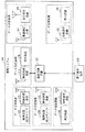
図1は、本実施の形態に係る車載システムの構成例を示すブロック図である。
通信制御装置110は、ネットワーク全体の通信を管理し、各端末の無線通信帯域割り当てを行う。
なお、端末とは、後述の撮像装置120、撮像装置130、再生装置140、放送受信装置160の総称である。
無線通信装置111は、車内の他の無線通信装置と無線通信を行う。
撮像装置120は、車両前方を撮影するカメラである。
無線通信装置121は、車内の他の無線通信装置と無線通信を行う。
撮像装置130は、車両後方を撮影するカメラである。
無線通信装置131は、車内の他の無線通信装置と無線通信を行う。
再生装置140は、Blu−ray(登録商標)やDVD等のディスクドライブから成る。
無線通信装置141は、車内の他の無線通信装置と無線通信を行う。
放送受信装置160は、放送電波を受信するアンテナとチューナーで構成される。
無線通信装置161は、車内の他の無線通信装置と無線通信を行う。
表示装置170は、フロントシート側に配置され、映像情報や地図、案内画面等を表示する。
表示装置180は、リアシート側に配置され、主に映像情報を表示する。
無線通信装置181は、車内の他の無線通信装置と無線通信を行う。
FIG. 1 is a block diagram illustrating a configuration example of an in-vehicle system according to the present embodiment.
The
The term “terminal” is a generic term for an
The
The
The
The
The
The
The
The
The
The
The
The
電子制御装置150は、ギア制御、ハンドル制御、アクセル制御、ブレーキ制御等車両の走行に必要な制御を行う。
また、電子制御装置150は、車両の進行方向(前進/後退)、走行速度に関する情報である走行情報を通信制御装置110に対して出力する。
The
In addition, the
表示装置170は、撮像装置120、撮像装置130、再生装置140、放送受信装置160から、それぞれ無線通信装置121、131、141、161を通して送信される映像データや音声データを、無線通信装置111を通して受信し、表示し、また音声出力する。
表示形態は、前記4つの映像から1つを選択して表示する場合と、複数を選択して同時に表示する場合とがある。
また、地図画面や案内画面のみを表示し、映像情報を表示しない場合もある。
また、音声データのみを出力してもよい。
The
There are cases where one of the four videos is selected for display and another is selected for display simultaneously.
In some cases, only the map screen and the guidance screen are displayed, and the video information is not displayed.
Further, only audio data may be output.
表示装置180は、撮像装置120、撮像装置130、再生装置140、放送受信装置160から、それぞれ無線通信装置121、131、141、161を通して送信される映像データを、無線通信装置181を通して受信し、表示し、また音声出力する。
表示形態は、前記4つの映像から1つを選択して表示する場合と、複数を選択して同時に表示する場合とがある。
また、地図画面や案内画面のみを表示し、映像情報を表示しない場合もある。
また、音声データのみを出力してもよい。
The
There are cases where one of the four videos is selected for display and another is selected for display simultaneously.
In some cases, only the map screen and the guidance screen are displayed, and the video information is not displayed.
Further, only audio data may be output.
無線通信装置111は、各端末から送信される無線信号のエラーレートから現在の実効通信帯域を算出し、その合計値を通信制御装置110に対して出力する。
The
このように、撮像装置120、撮像装置130、再生装置140、放送受信装置160は、それぞれ無線通信装置121、131、141、161を通して映像データや音声データを送信しており、撮像装置120と無線通信装置121との組合せ、撮像装置130と無線通信装置131との組合せ、再生装置140と無線通信装置141との組合せ、放送受信装置160と無線通信装置161との組合せは、それぞれデータ送信装置の例である。
なお、以下では、それぞれの組合せを区別する必要のない場合は、これらの組合せの総称としてデータ送信装置と表記する。
撮像装置120、撮像装置130、再生装置140、放送受信装置160は、総称して端末ともいう。
As described above, the
Hereinafter, when there is no need to distinguish each combination, the combination of these combinations is referred to as a data transmission device.
The
また、表示装置170は無線通信装置111を介してデータ送信装置からのデータを受信し、表示装置180は無線通信装置181を介してデータ送信装置からのデータを受信しており、表示装置170と無線通信装置111との組合せ、表示装置180と無線通信装置181との組合せは、それぞれデータ受信装置の例である。
なお、以下では、それぞれの組合せを区別する必要のない場合は、これらの組合せの総称としてデータ受信装置と表記する。
また、前述の通り、撮像装置120、撮像装置130、再生装置140、放送受信装置160は、総称して端末ともいう。
The
Hereinafter, when there is no need to distinguish each combination, the combination of these combinations is referred to as a data receiving device.
As described above, the
例えば、車載システム100の起動後、通信制御装置110は、無線通信装置111を通して各端末の無線通信割り当て帯域を定義する帯域割り当てテーブルの情報を送信する。
撮像装置120、撮像装置130、再生装置140、放送受信装置160は帯域割り当てテーブルの情報をもとに発生符号量を制御する。
発生符号量の制御としては、フレームサイズ、フレームレート、量子化値等符号化パラメータの何れか、あるいはそれらの複数を変更することで行う。
なお、後述するように、通信制御装置110は、帯域割り当てテーブル全体の情報を送信せずに、各端末に割り当てる無線通信帯域を変更する決定をする度に、変更後の無線通信帯域を通知する情報を送信するようにしてもよい。
For example, after the in-
The
The generated code amount is controlled by changing any one or a plurality of encoding parameters such as a frame size, a frame rate, and a quantization value.
As will be described later, the
図2に実施の形態1における帯域割り当てテーブルの例を示す。 FIG. 2 shows an example of the bandwidth allocation table in the first embodiment.
帯域割り当てテーブルは、車両の走行に関する状態が運転状況として複数示されるとともに複数段階の無線通信帯域レベル(図2の例では、20Mbps、16Mbps、12Mbps、8Mbps)が実効帯域として示される。
そして、運転状況と実効帯域の組合せごとに、各データ送信装置に割り当てられる無線通信帯域の割り当て比率が示されるサブテーブルTable1−1〜Table4−4が設けられている。
なお、実効帯域は、前述したように、無線通信装置111において各データ送信装置からのデータを受信する際に計測された無線通信帯域の合計値である。
また、各サブテーブルでは、運転状況ごとに、車両がその運転状況にあるときに車両の搭乗者にとって重要と推測されるデータを送信するデータ送信装置ほど高い割り当て比率が設定されている。
具体的には、停止中は、再生装置や放送受信装置といったエンターテイメント系の端末により多くの帯域を割り当て、全体の通信帯域が落ちると、ほぼそれに比例して全体の帯域を落とす。
通常走行では、停止中に比べて前方カメラ、後方カメラといった安全系の端末に割り当てる帯域を増やす。
加速中では、前方カメラに割り当てる帯域を増やし、全体の実効通信帯域が落ちても前方カメラに割り当てる帯域を確保する。
逆に減速中やバック運転中は、後方カメラに割り当てる帯域を増やし、全体の実効通信帯域が落ちても後方カメラに割り当てる帯域を確保する。
なお、帯域割り当てテーブルは、割り当て比率情報の例である。
In the bandwidth allocation table, a plurality of states related to the traveling of the vehicle are indicated as driving situations, and a plurality of stages of wireless communication bandwidth levels (20 Mbps, 16 Mbps, 12 Mbps, and 8 Mbps in the example of FIG. 2) are indicated as effective bandwidths.
Then, sub-tables Table 1-1 to Table 4-4 are provided that indicate the allocation ratios of the radio communication bands allocated to the respective data transmission apparatuses for each combination of the driving situation and the effective band.
As described above, the effective band is the total value of the wireless communication bands measured when the
In each sub-table, for each driving situation, a higher allocation ratio is set for a data transmission device that transmits data that is presumed to be important for a passenger of the vehicle when the vehicle is in the driving situation.
Specifically, during stoppage, more bands are allocated to entertainment-type terminals such as playback devices and broadcast receiving devices, and when the overall communication bandwidth is reduced, the overall bandwidth is reduced almost in proportion to it.
In normal driving, the bandwidth allocated to safety-type terminals such as the front camera and rear camera is increased compared to when the vehicle is stopped.
During acceleration, the bandwidth allocated to the front camera is increased, and the bandwidth allocated to the front camera is secured even if the overall effective communication bandwidth drops.
Conversely, during deceleration or back-drive, the bandwidth allocated to the rear camera is increased, and the bandwidth allocated to the rear camera is secured even if the overall effective communication bandwidth is reduced.
The bandwidth allocation table is an example of allocation ratio information.
通信制御装置110は、電子制御装置150から得られる進行方向、走行速度に関する情報と、無線通信装置111から得られる実効通信帯域の合計値をもとに、図2のサブテーブル群のうち該当するサブテーブルを選択する。
また、サブテーブルが変更になる場合、帯域通知情報として、例えば、そのサブテーブルの番号(Table1−1等)を、無線通信装置111を通して各端末に送信する。
また、帯域割り当てテーブルの全体を各端末に送信していない場合は、通信制御装置110は、帯域通知情報として、選択したサブテーブルそのものを無線通信装置111を通して各端末に送信するようにしてもよい。
また、帯域割り当てテーブルの全体を各端末に送信していない場合は、通信制御装置110は、選択したサブテーブルをもとにして、端末ごとに個別の通信帯域を計算して、帯域通知情報として、計算結果を通知するようにしてもよい。
無線通信装置111は、通信制御装置110から受信したサブテーブル番号、サブテーブル内の端末ごとの無線通信帯域、計算された端末ごとの無線通信帯域のいずれかを各端末に送信する。
また、無線通信装置111は、計測した端末ごと(無線通信装置121、131、141、161ごと)の実効通信帯域を、各端末に送信する。
The
Further, when the subtable is changed, for example, the number of the subtable (Table1-1 or the like) is transmitted to each terminal through the
When the entire bandwidth allocation table is not transmitted to each terminal, the
If the entire bandwidth allocation table has not been transmitted to each terminal, the
The
In addition, the
撮像装置120、撮像装置130、再生装置140、放送受信装置160は、それぞれ無線通信装置121、131、141、160を通して、無線通信装置111から送信されるサブテーブル番号、サブテーブル内の端末ごとの通信帯域、計算された端末ごとの通信帯域のいずれかを受信し、更に、端末個別の実効通信帯域を受信する。
The
撮像装置120、撮像装置130、再生装置140、放送受信装置160は、サブテーブル番号の更新に伴い、サブテーブルに記載された割り当て帯域に収まるよう発生符号量を制御する。
また、端末個別の実効通信帯域と送信待ちデータの容量から、データの転送時間を算出する。
この転送時間と閾値とを比較し、閾値を超えていた場合はサブテーブルの番号をローカルに変更し、変更後の割り当て帯域に従って符号化制御する。
The
Also, the data transfer time is calculated from the effective communication bandwidth of each terminal and the capacity of the data waiting for transmission.
This transfer time is compared with a threshold value, and if the threshold value is exceeded, the sub-table number is changed locally, and encoding control is performed according to the changed allocated bandwidth.
次に、図6を参照して、本実施の形態に係る通信制御装置110の構成例を説明する。
Next, a configuration example of the
図6において、電子制御装置I/F(インタフェース)部1106は、電子制御装置150から車両の進行方向(前進/後退)、走行速度に関する情報である走行情報を入力する。
In FIG. 6, an electronic control unit I / F (interface)
状態判定部1105は、電子制御装置I/F部1106が電子制御装置150から入力した走行情報から、車両の状態を判定する。
状態判定部1105は、例えば、電子制御装置150からの走行情報に示される走行速度が0Km/hであった場合には、車両が停止中と判断し、また、前回の走行情報に示された走行速度と今回の走行情報に示された走行速度との変化量が所定の閾値以下であれば、通常走行であると判断する。
また、今回の走行情報に示された走行速度が前回の走行情報に示された走行速度よりも速く、また、変化量が所定の閾値を超えていれば加速中であると判断し、今回の走行情報に示された走行速度が前回の走行情報に示された走行速度よりも遅く、また、変化量が所定の閾値を超えていれば減速中であると判断する。
更に、電子制御装置150からの進行方向情報に示される進行方向が後退であれば、バック運転中であると判断する。
なお、状態判定部1105による状態判定の手法は、これらに限られない。
The
For example, when the traveling speed indicated in the traveling information from the
In addition, if the travel speed indicated in the current travel information is faster than the travel speed indicated in the previous travel information and the amount of change exceeds a predetermined threshold, it is determined that the vehicle is accelerating. If the travel speed indicated in the travel information is slower than the travel speed indicated in the previous travel information and the change amount exceeds a predetermined threshold, it is determined that the vehicle is decelerating.
Further, if the traveling direction indicated by the traveling direction information from the
Note that the method of state determination by the
情報記憶部1104は、図2に示した帯域割り当てテーブルを記憶している。
The
通信帯域決定部1103は、状態判定部1105により判定された車両の状態と、各データ送信装置の属性と、無線通信装置111により計測された無線通信帯域(実効通信帯域の合計値)に基づき、データ送信装置ごとに、割り当てる無線通信帯域を決定する。
より具体的には、図2の帯域割り当てテーブルのサブテーブル群のうち、状態判定部1105により判定された車両の状態と、無線通信装置111により計測された無線通信帯域(実効通信帯域の合計値)の組合せに該当するテーブルを抽出し、抽出したテーブルに基づき、端末ごとの無線通信帯域を決定する。
The communication
More specifically, in the sub-table group of the bandwidth allocation table of FIG. 2, the vehicle state determined by the
通信帯域通知部1102は、通信帯域決定部1103により決定された通信帯域を通知する帯域通知情報を生成し、帯域通知情報を無線通信装置I/F部1101から無線通信装置111に送信し、無線通信装置111から各データ送信装置に無線通信帯域を通知する。
The communication
無線通信装置I/F部1101は、無線通信装置111から実効帯域を通知する帯域情報を受信したり、各データ送信装置に割り当てられた帯域を通知する帯域通知情報を無線通信装置111に送信する。
The wireless communication apparatus I /
次に、図7を参照して、本実施の形態に係る通信制御装置110の動作例を説明する。
Next, an operation example of the
まず、電子制御装置I/F部1106が、電子制御装置150から車両の進行方向(前進/後退)、走行速度に関する情報である走行情報を入力し、入力した走行情報を状態判定部1105に出力し、状態判定部1105が走行情報に基づき、運転状況(車両の走行状態)を判定する(S701)。
また、状態判定部1105は、判定結果を通信帯域決定部1103に出力する。
次に、無線通信装置I/F部1101が、無線通信装置111から実効帯域を通知する帯域情報を受信し、受信した帯域情報を通信帯域決定部1103に出力し、通信帯域決定部1103は帯域情報に示されている実行帯域を確認する(S702)。
なお、S701とS702の順序は入れ替わってもよい。
First, the electronic control device I /
Further, the
Next, the wireless communication apparatus I /
Note that the order of S701 and S702 may be switched.
通信帯域決定部1103は、前回の運転状況及び実効帯域を記憶しており、現在の運転状況(S701で判定された状態)及び実効帯域(S702で確認された実効帯域)が前回の運転状況及び実効帯域と変化しているかを判断し(S703)、運転状況及び実効帯域の両方において変化がなければ、処理を終了し、一方、少なくともいずかに変化がある場合には、図2の帯域割り当てテーブルのうち、現在の運転状況及び実効帯域に該当するサブテーブルを抽出する(S704)。
なお、現在の実効帯域が図2の帯域割り当てテーブルに示されている値以外の場合、例えば、車両が現在「停止中」であって、実効帯域が「18Mbps」である場合は、実効帯域「16Mbps」以上であって「20Mbps」未満なので、サブテーブルTable1−2を選択する。
The communication
When the current effective bandwidth is other than the value shown in the bandwidth allocation table of FIG. 2, for example, when the vehicle is currently “stopped” and the effective bandwidth is “18 Mbps”, the effective bandwidth “ Since it is equal to or greater than “16 Mbps” and less than “20 Mbps”, the sub-table Table1-2 is selected.
次に、通信帯域決定部1103が、抽出したサブテーブルに基づき、各端末に割り当てる無線通信帯域を決定する(S705)。
例えば、選択したサブテーブルに示されている各端末の帯域をそのまま用いてもよいし、前述のように、現在の実効帯域が図2の帯域割り当てテーブルに示されている値以外の場合は、現実の実効帯域と選択したサブテーブルの実効帯域との差異に基づいて各端末の帯域を計算してもよい。
前述のように、実効帯域が「18Mbps」であり、サブテーブルTable1−2が選択された場合には、例えば、以下のように計算する。
前方カメラの帯域:(18/16)×1≒1.13Mbps
後方カメラの帯域:(18/16)×1≒1.13Mbps
再生装置の帯域:(18/16)×7≒7.88Mbps
放送受信装置の帯域:(18/16)×7≒7.88Mbps
なお、計算方法はこれに限らない。
Next, the communication
For example, the bandwidth of each terminal indicated in the selected sub-table may be used as it is, or as described above, when the current effective bandwidth is other than the value indicated in the bandwidth allocation table of FIG. The bandwidth of each terminal may be calculated based on the difference between the actual effective bandwidth and the effective bandwidth of the selected sub-table.
As described above, when the effective bandwidth is “18 Mbps” and the sub-table Table1-2 is selected, for example, the following calculation is performed.
Front camera bandwidth: (18/16) × 1≈1.13 Mbps
Rear camera bandwidth: (18/16) × 1≈1.13 Mbps
Band of playback device: (18/16) × 7≈7.88 Mbps
Broadcast receiver bandwidth: (18/16) × 7≈7.88 Mbps
The calculation method is not limited to this.
次に、通信帯域通知部1102が、通信帯域決定部1103により決定された通信帯域を通知する帯域通知情報を生成する(S706)。
各端末が、図2の帯域割り当てテーブルの全サブテーブル(Table1−1〜Table4−4)を保持しており、また、S704において選択されたサブテーブルに示されている各端末の割り当て帯域をそのまま用いる場合は、通信帯域通知部1102は、S704で選択されたサブテーブルの番号(Table2−1等)を通知する帯域通知情報を生成する。
また、各端末が、図2の帯域割り当てテーブルの全サブテーブル(Table1−1〜Table4−4)を保持しておらず、また、S704において選択されたサブテーブルに示されている各端末の割り当て帯域をそのまま用いる場合は、通信帯域通知部1102は、S704で選択されたサブテーブルにおける各端末の割り当て帯域の値を通知する帯域通知情報を生成する。
また、通信帯域決定部1103により計算された帯域を各端末に割り当てる場合は、通信帯域決定部1103により計算された各端末の割り当て帯域の値を通知する帯域通知情報を生成する。
Next, the communication
Each terminal holds all the sub-tables (Table 1-1 to Table 4-4) of the bandwidth allocation table of FIG. 2, and the allocated bandwidth of each terminal shown in the sub-table selected in S704 is used as it is. When used, the communication
Further, each terminal does not hold all the sub-tables (Table 1-1 to Table 4-4) of the bandwidth allocation table of FIG. 2, and the allocation of each terminal shown in the sub-table selected in S704 When the band is used as it is, the communication
Further, when the bandwidth calculated by the communication
最後に、通信帯域通知部1102が、S706で生成した帯域通知情報を無線通信装置I/F部1101から無線通信装置111に送信し、無線通信装置111から各データ送信装置に帯域通知情報を送信する(S707)。
Finally, the communication
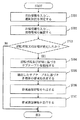
次に、割り当て帯域を通知された各端末において、割り当て帯域に基づいて発生符号量を制御する手法を図3を用いて説明する。
図3は、各端末で実施される発生符号量を制御する処理のフローチャートである。
なお、図3は、各端末が図2の帯域割り当てテーブルの全てのサブテーブルを予め保有していることを前提としている。
Next, a method of controlling the amount of generated code based on the allocated bandwidth in each terminal that has been notified of the allocated bandwidth will be described with reference to FIG.
FIG. 3 is a flowchart of a process for controlling the amount of generated code executed in each terminal.
Note that FIG. 3 is based on the premise that each terminal previously holds all sub-tables of the bandwidth allocation table of FIG.
S300では、端末は、バッファに蓄積されている送信待ちデータの容量と端末毎の実効通信帯域から、送信待ちデータ全てを送信し終えるまでの転送時間を算出する。
S301では、S300で算出した転送完了時間と閾値とを比較する。
送信完了時間が閾値以下の場合は何もせず処理完了するが、送信完了時間が閾値より大きい場合はS302に進む。
S302では、端末は、使用するサブテーブルを、帯域が小さい条件のテーブル番号に変更する。
S303では、S302で変更されたテーブルに定義されている割り当て帯域になるよう発生符号量を制御し、S300に戻る。
つまり、新たに生成するデータの符号化レートを、通信制御装置110により通知された無線通信帯域に対応する符号化レートよりも少ない符号化レートとする。
In S300, the terminal calculates the transfer time until the transmission of all the transmission waiting data is completed from the capacity of the transmission waiting data stored in the buffer and the effective communication band for each terminal.
In S301, the transfer completion time calculated in S300 is compared with a threshold value.
If the transmission completion time is less than or equal to the threshold, the process is completed without doing anything, but if the transmission completion time is greater than the threshold, the process proceeds to S302.
In S302, the terminal changes the sub-table to be used to a table number under a condition that the bandwidth is low.
In S303, the generated code amount is controlled so as to be the allocated band defined in the table changed in S302, and the process returns to S300.
That is, the encoding rate of newly generated data is set to a lower encoding rate than the encoding rate corresponding to the wireless communication band notified by the
なお、S301で参照する閾値は、車載システム100の起動後に通信制御装置110から各端末に送信してもよいし、あらかじめ各端末が固定値を保持していてもよい。
In addition, the threshold value referred by S301 may be transmitted to each terminal from the
このように、本実施の形態では、通信制御装置が伝送帯域の大きさによって伝送帯域の割り当て比率を変更することが出来るようにしたので、車両の運転状況によって決まる重要な映像データは、伝送帯域が変動しても必要な精度を保ちつつリアルタイムで伝送することが出来る。 As described above, in the present embodiment, the communication control apparatus can change the transmission band allocation ratio according to the size of the transmission band. Therefore, the important video data determined by the driving situation of the vehicle is the transmission band. Even if fluctuates, it can be transmitted in real time while maintaining the required accuracy.
また、本実施の形態では、各端末が映像データの伝送完了時間を算出し、それが伝送帯域毎に設定された閾値を超えている場合に発生符号量を制御するようにしたので、表示される映像が停止したり遅れること無く伝送することが出来る。 Further, in this embodiment, each terminal calculates the transmission completion time of video data, and controls the amount of generated code when it exceeds the threshold set for each transmission band. Can be transmitted without stopping or delaying.
以上、本実施の形態では、
車外或いは車内の様子を撮影する撮像装置と、DVDプレーヤー、Blu−ray(登録商標)ディスクプレーヤーといったビデオソースを媒体から読み出す再生装置と、放送電波を受信する放送受信装置と、映像データを表示する表示装置と、車内で無線通信を行う無線通信装置と、自車の走行内容を制御する電子制御装置と、各端末間の通信帯域を制御する通信制御装置とで構成される車載システムにおいて、
前記通信制御装置は、前記電子制御装置から得られた情報に従って各端末に通信帯域を割り当てる際に、伝送帯域の大きさによって伝送帯域の割り当て比率を変更することが可能であることを説明した。
As described above, in the present embodiment,
An image pickup device that captures a state outside or inside the vehicle, a playback device that reads a video source from a medium, such as a DVD player or a Blu-ray (registered trademark) disk player, a broadcast receiver that receives broadcast radio waves, and video data are displayed. In an in-vehicle system composed of a display device, a wireless communication device that performs wireless communication in the vehicle, an electronic control device that controls the traveling content of the host vehicle, and a communication control device that controls a communication band between the terminals,
It has been explained that the communication control device can change the allocation ratio of the transmission band according to the size of the transmission band when allocating the communication band to each terminal according to the information obtained from the electronic control device.
また、本実施の形態では、
前記通信制御装置は、各装置端末が送信しようとしている映像データの伝送完了時間を算出し、伝送完了時間が閾値を超えている端末に対して符号化制御を行い、発生符号量を抑制することを説明した。
In the present embodiment,
The communication control device calculates the transmission completion time of video data that each device terminal intends to transmit, performs coding control on the terminal whose transmission completion time exceeds a threshold, and suppresses the generated code amount Explained.
実施の形態2.
図4は、本実施の形態に係る車載システムの構成例を示すブロック図である。
図4では、図1と同じ要素には同じ符号を用いている。
また、図1と同じ要素については説明を省略する。
図1では、通信制御装置110は電子制御装置150に接続され、電子制御装置150から走行情報を入力していたが、図4では、通信制御装置110はセンサー450〜452に接続され、センサー450〜452からセンサー情報を入力する。
センサー450〜452は、車両の周辺環境を監視するセンサーである。
例えば、センサー450は、GPS(Global Positioning System)、方位センサー、車速センサー、地図情報記憶装置と、これらから得られる情報をもとに車両位置と進行方向を判定する判定装置で構成される。
センサー451は、電波や赤外線等で前方障害物を検知するレーダーである。
センサー451は、電波や赤外線等で後方障害物を検知するレーダーである。
より具体的には、センサー450は、GPS、方位センサー、車速センサーから得られる情報と地図情報を組み合わせて、自車位置と進行方向を判定する。また、地図情報から自車が見通しの悪い交差点やカーブに差し掛かっているかを判定し、その情報を通信制御装置110に出力する。
センサー451は、電波あるいは赤外線レーダーにより、歩行者、前方走行車、対向車等の前方障害物の接近を検知し、その情報を通信制御装置110に出力する。
センサー452は、電波あるいは赤外線レーダーにより、歩行者、後方走行車等の後方障害物の接近を検知し、その情報を通信制御装置110に出力する。
FIG. 4 is a block diagram illustrating a configuration example of the in-vehicle system according to the present embodiment.
In FIG. 4, the same reference numerals are used for the same elements as in FIG.
Further, description of the same elements as those in FIG. 1 is omitted.
In FIG. 1, the
For example, the
The
The
More specifically, the
The
The
図5に、実施の形態2における帯域割り当てテーブルの例を示す。
通常状態では、再生装置や放送受信装置といったエンターテイメント系の端末に帯域を割り当て、全体の通信帯域が落ちると、ほぼそれに比例して全体の帯域を落とす。
進行方向の見通しが悪い場合は、前方カメラに重点的に帯域を割り当て、全体の実効通信帯域が落ちても前方カメラに割り当てる帯域を確保する。
前方に障害物が接近した場合は、前方カメラに重点的に帯域を割り当て、全体の実効通信帯域が落ちても前方カメラに割り当てる帯域は全く落とさない。
逆に後方に障害物が接近した場合は、後方カメラに重点的に帯域を割り当て、全体の実効通信帯域が落ちても後方カメラに割り当てる帯域は全く落とさない。
FIG. 5 shows an example of a bandwidth allocation table in the second embodiment.
In the normal state, a bandwidth is allocated to entertainment-type terminals such as a playback device and a broadcast receiving device, and when the overall communication bandwidth is reduced, the overall bandwidth is reduced in proportion to it.
If the forward direction is poor, a bandwidth is allocated to the front camera with priority, and a bandwidth to be allocated to the front camera is secured even if the overall effective communication bandwidth drops.
When an obstacle approaches the front, a bandwidth is assigned to the front camera with priority, and even if the overall effective communication bandwidth is reduced, the bandwidth assigned to the front camera is not dropped at all.
On the other hand, when an obstacle approaches the rear, a bandwidth is assigned to the rear camera with priority, and even if the overall effective communication bandwidth is reduced, the bandwidth assigned to the rear camera is not reduced at all.
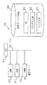
図8は、本実施の形態に係る通信制御装置110の構成を示す。
図8の構成は、電子制御装置I/F(インタフェース)部1106の代わりにセンサーI/F部1107が設けられている点を除けば、図6の構成と同じである。
センサーI/F部1107は、センサー450〜452の測定結果、判定結果が示されるセンサー情報を入力する。
また、本実施の形態では、状態判定部1105は、センサー情報に基づき、車両の周辺環境の状態が、図5の運転状況に示される「通常状態」、「進行方向見通し不良」、「前方障害物接近」、「後方障害物接近」のいずれであるかを判定する。
また、本実施の形態に係る情報記憶部1104は、図5に示した帯域割り当てテーブルを記憶している。
また、本実施の形態に係る通信帯域決定部1103は、図5の帯域割り当てテーブルのサブテーブルの中から、状態判定部1105の判定結果及び無線通信装置111で計測された実効帯域に該当するサブテーブルを選択する。
他の要素の動作は、実施の形態1と同様である。
FIG. 8 shows a configuration of
The configuration of FIG. 8 is the same as the configuration of FIG. 6 except that a sensor I /
The sensor I /
Further, in the present embodiment, the
Further, the
In addition, the communication
The operation of other elements is the same as that of the first embodiment.
図9は、本実施の形態に係る通信制御装置110の動作例を示すフローチャートである。
なお、図7と同様の処理には、図7と同じ符号を付している。
FIG. 9 is a flowchart showing an operation example of the
In addition, the same code | symbol as FIG. 7 is attached | subjected to the process similar to FIG.
まず、センサーI/F部1107が、センサー450〜452からセンサー情報を入力し、入力しセンサー情報を状態判定部1105に出力し、状態判定部1105がセンサー情報に基づき、運転状況(車両の周辺環境の状態)を判定する(S901)。
また、状態判定部1105は、判定結果を通信帯域決定部1103に出力する。
次に、無線通信装置I/F部1101が、無線通信装置111から実効帯域を通知する帯域情報を受信し、受信した帯域情報を通信帯域決定部1103に出力し、通信帯域決定部1103は帯域情報に示されている実効帯域を確認する(S702)。
なお、S901とS702の順序は入れ替わってもよい。
First, the sensor I /
Further, the
Next, the wireless communication apparatus I /
Note that the order of S901 and S702 may be switched.
通信帯域決定部1103は、前回の運転状況及び実効帯域を記憶しており、現在の運転状況(S901で判定された状態)及び実効帯域(S702で確認された実効帯域)が前回の運転状況及び実効帯域と変化しているかを判断し(S703)、運転状況及び実効帯域の両方において変化がなければ、処理を終了し、一方、少なくともいずかに変化がある場合には、図5の帯域割り当てテーブルのうち、現在の運転状況及び実効帯域に該当するサブテーブルを抽出する(S704)。
なお、現在の実効帯域が図5の帯域割り当てテーブルに示されている値以外の場合、例えば、車両が現在「通常状態」であって、実効帯域が「18Mbps」である場合は、実効帯域「16Mbps」以上であって「20Mbps」未満なので、サブテーブルTable1−2を選択する。
The communication
When the current effective bandwidth is other than the value shown in the bandwidth allocation table of FIG. 5, for example, when the vehicle is currently in the “normal state” and the effective bandwidth is “18 Mbps”, the effective bandwidth “ Since it is equal to or greater than “16 Mbps” and less than “20 Mbps”, the sub-table Table1-2 is selected.
次に、通信帯域決定部1103が、抽出したサブテーブルに基づき、各端末に割り当てる無線通信帯域を決定する(S705)。
例えば、選択したサブテーブルに示されている各端末の帯域をそのまま用いてもよいし、前述のように、現在の実効帯域が図5の帯域割り当てテーブルに示されている値以外の場合は、現実の実効帯域と選択したサブテーブルの実効帯域との差異に基づいて各端末の帯域を計算してもよい。
以降の動作は、実施の形態1で示した図7と同じであるため、説明を省略する。
Next, the communication
For example, the bandwidth of each terminal indicated in the selected sub-table may be used as it is. As described above, when the current effective bandwidth is other than the value indicated in the bandwidth allocation table of FIG. The bandwidth of each terminal may be calculated based on the difference between the actual effective bandwidth and the effective bandwidth of the selected sub-table.
Subsequent operations are the same as those in FIG. 7 described in the first embodiment, and a description thereof will be omitted.
なお、各端末の伝送割り当て帯域を決定するテーブルのパラメータに、実施の形態1で説明した車両の走行内容と、実施の形態2で説明した車両周辺の状況を組み合わせてもよい。 The vehicle parameters described in the first embodiment and the vehicle surroundings described in the second embodiment may be combined with the parameters of the table for determining the transmission allocation bandwidth of each terminal.
また、実施の形態1及び2では、映像信号は全て無線で通信を行うようになっているが、一部は有線であってもよいし、制御信号の一部は有線で通信を行うようになっているが、これらを無線で通信してもよい。 In the first and second embodiments, all video signals are communicated wirelessly. However, some video signals may be wired, and some control signals may be wired. However, these may be communicated wirelessly.
以上、本実施の形態では、通信制御装置が伝送帯域の大きさによって伝送帯域の割り当て比率を変更することが出来るようにしたので、車両の周辺状況によって決まる重要な映像データは、伝送帯域が変動しても必要な精度を保ちつつリアルタイムで伝送することが出来る。 As described above, in this embodiment, since the communication control apparatus can change the transmission band allocation ratio according to the size of the transmission band, the transmission band of the important video data determined by the surrounding situation of the vehicle varies. Even so, it can be transmitted in real time while maintaining the required accuracy.
以上、本実施の形態では、
車外或いは車内の様子を撮影する撮像装置と、DVDプレーヤー、Blu−ray(登録商標)ディスクプレーヤーといったビデオソースを媒体から読み出す再生装置と、放送電波を受信する放送受信装置と、映像データを表示する表示装置と、車内で無線通信を行う無線通信装置と、自車位置・障害物との距離等車両周辺の状況を測定するセンサーと、各端末間の通信帯域を制御する通信制御装置とで構成される車載システムにおいて、
前記通信制御装置は、前記センサーから得られた情報に従って各端末に通信帯域を割り当てる際に、伝送帯域の大きさによって伝送帯域の割り当て比率を変更することが可能であることを説明した。
As described above, in the present embodiment,
An image pickup device that captures a state outside or inside the vehicle, a playback device that reads a video source from a medium, such as a DVD player or a Blu-ray (registered trademark) disk player, a broadcast receiver that receives broadcast radio waves, and video data are displayed. Consists of a display device, a wireless communication device that performs wireless communication in the vehicle, a sensor that measures the situation around the vehicle, such as the position of the vehicle and the distance to obstacles, and a communication control device that controls the communication band between each terminal In-vehicle system
It has been explained that the communication control apparatus can change the allocation ratio of the transmission band according to the size of the transmission band when allocating the communication band to each terminal according to the information obtained from the sensor.
なお、図2及び図5の帯域割り当てテーブルは、複数の実効帯域のレベル(20Mbps、16Mbps、12Mbps、8Mbps)が示され、各レベルに対してサブテーブルが設けられているが、これを1つの実効帯域の値としてもよい。
例えば、実効帯域20MbpsのサブテーブルであるサブテーブルTable1−1、2−1、3−1、4−1、5−1のみを帯域割り当てテーブルに設けるようにしてもよい。
このような帯域割り当てテーブルを用いる場合には、通信帯域決定部1103において、実際に計測された実効帯域と実効帯域20Mbpsとの差に対応させて、各端末の割り当て帯域を計算する。
例えば、図2の帯域割り当てテーブルを用いる場合に、運転状況が「停止中」であり、実際に計測された実効帯域が「16Mbps」である場合は、サブテーブルTable1−1が選択され、例えば、以下のように計算する。
前方カメラの帯域:(16/20)×2=1.6Mbps
後方カメラの帯域:(16/20)×2=1.6Mbps
再生装置の帯域:(16/20)×8=6.4Mbps
放送受信装置の帯域:(16/20)×8=6.4Mbps
なお、計算方法はこれに限らない。
2 and 5 show a plurality of effective bandwidth levels (20 Mbps, 16 Mbps, 12 Mbps, and 8 Mbps), and sub-tables are provided for each level. The effective band value may be used.
For example, only the sub-tables Tables 1-1, 2-1, 3-1, 4-1, and 5-1 that are sub-tables with an effective bandwidth of 20 Mbps may be provided in the bandwidth allocation table.
When such a band allocation table is used, the communication
For example, when the bandwidth allocation table of FIG. 2 is used, when the operation status is “stopped” and the actually measured effective bandwidth is “16 Mbps”, the sub-table Table1-1 is selected. Calculate as follows.
Front camera bandwidth: (16/20) × 2 = 1.6 Mbps
Rear camera bandwidth: (16/20) × 2 = 1.6 Mbps
Band of playback device: (16/20) × 8 = 6.4 Mbps
Broadcast receiver bandwidth: (16/20) × 8 = 6.4 Mbps
The calculation method is not limited to this.
最後に、実施の形態1及び2に示した通信制御装置110のハードウェア構成例について説明する。
図10は、実施の形態1及び2に示す通信制御装置110のハードウェア資源の一例を示す図である。
なお、図10の構成は、あくまでも通信制御装置110のハードウェア構成の一例を示すものであり、通信制御装置110のハードウェア構成は図10に記載の構成に限らず、他の構成であってもよい。
Finally, a hardware configuration example of the
FIG. 10 is a diagram illustrating an example of hardware resources of the
The configuration in FIG. 10 is merely an example of the hardware configuration of the
図10において、通信制御装置110は、プログラムを実行するCPU911(Central Processing Unit、中央処理装置、処理装置、演算装置、マイクロプロセッサ、マイクロコンピュータ、プロセッサともいう)を備えている。
CPU911は、バス912を介して、例えば、ROM(Read Only Memory)913、RAM(Random Access Memory)914、通信ボード915、磁気ディスク装置920と接続され、これらのハードウェアデバイスを制御する。
また、磁気ディスク装置920の代わりに、SSD(Solid State Drive)、光ディスク装置、メモリカード(登録商標)読み書き装置などの記憶装置でもよい。
RAM914は、揮発性メモリの一例である。ROM913、磁気ディスク装置920の記憶媒体は、不揮発性メモリの一例である。これらは、記憶装置の一例である。
実施の形態1及び2で説明した「情報記憶部1104」は、RAM914、磁気ディスク装置920等により実現される。
通信ボード915は、入力装置及び出力装置の一例である。
In FIG. 10, the
The
Further, instead of the
The
The “
The
通信ボード915は、無線通信装置111、電子制御装置150又はセンサー450〜452に接続されている。
The
磁気ディスク装置920には、オペレーティングシステム921(OS)、プログラム群923、ファイル群924が記憶されている。
プログラム群923のプログラムは、CPU911がオペレーティングシステム921を利用しながら実行する。
The
The programs in the
また、RAM914には、CPU911に実行させるオペレーティングシステム921のプログラムやアプリケーションプログラムの少なくとも一部が一時的に格納される。
また、RAM914には、CPU911による処理に必要な各種データが格納される。
The
The
また、ROM913には、BIOS(Basic Input Output System)プログラムが格納され、磁気ディスク装置920にはブートプログラムが格納されている。
通信制御装置110の起動時には、ROM913のBIOSプログラム及び磁気ディスク装置920のブートプログラムが実行され、BIOSプログラム及びブートプログラムによりオペレーティングシステム921が起動される。
The
When the
上記プログラム群923には、実施の形態1及び2の説明において「〜部」(「情報記憶部」以外、以下同様)として説明している機能を実行するプログラムが記憶されている。プログラムは、CPU911により読み出され実行される。
The
ファイル群924には、実施の形態1及び2の説明において、「〜の判断」、「〜の判定」、「〜の計算」、「〜の比較」、「〜の抽出」、「〜の決定」、「〜の設定」、「〜の生成」、「〜の選択」等として説明している処理の結果を示す情報やデータや信号値や変数値やパラメータが、「〜ファイル」や「〜データベース」の各項目として記憶されている。
「〜ファイル」や「〜データベース」は、ディスクやメモリなどの記録媒体に記憶される。ディスクやメモリなどの記憶媒体に記憶された情報やデータや信号値や変数値やパラメータは、読み書き回路を介してCPU911によりメインメモリやキャッシュメモリに読み出され、抽出・検索・参照・比較・演算・計算・処理・編集・出力などのCPUの動作に用いられる。
抽出・検索・参照・比較・演算・計算・処理・編集・出力のCPUの動作の間、情報やデータや信号値や変数値やパラメータは、メインメモリ、レジスタ、キャッシュメモリ、バッファメモリ等に一時的に記憶される。
また、実施の形態1及び2で説明しているフローチャートの矢印の部分は主としてデータや信号の入出力を示し、データや信号値は、RAM914のメモリ、磁気ディスク装置920の磁気ディスク、SSD、その他光ディスク、DVD等の記録媒体に記録される。また、データや信号は、バス912や信号線やケーブルその他の伝送媒体によりオンライン伝送される。
In the
The “˜file” and “˜database” are stored in a recording medium such as a disk or a memory. Information, data, signal values, variable values, and parameters stored in a storage medium such as a disk or memory are read out to the main memory or cache memory by the
Information, data, signal values, variable values, and parameters are temporarily stored in the main memory, registers, cache memory, buffer memory, etc. during the CPU operation for extraction, search, reference, comparison, calculation, calculation, processing, editing, and output. Memorized.
The arrows in the flowcharts described in the first and second embodiments mainly indicate input / output of data and signals. The data and signal values are the memory of the
また、実施の形態1及び2の説明において「〜部」として説明しているものは、「〜回路」、「〜装置」、「〜機器」であってもよく、また、「〜ステップ」、「〜手順」、「〜処理」であってもよい。
すなわち、実施の形態1及び2で説明したフローチャートに示すステップ、手順、処理により、通信制御装置110の動作を方法として把握することができる。
また、「〜部」として説明しているものは、ROM913に記憶されたファームウェアで実現されていても構わない。或いは、ソフトウェアのみ、或いは、素子・デバイス・基板・配線などのハードウェアのみ、或いは、ソフトウェアとハードウェアとの組み合わせ、さらには、ファームウェアとの組み合わせで実施されても構わない。ファームウェアとソフトウェアは、プログラムとして、磁気ディスク、フレキシブルディスク、光ディスク、コンパクトディスク、ミニディスク、DVD等の記録媒体に記憶される。プログラムはCPU911により読み出され、CPU911により実行される。すなわち、プログラムは、実施の形態1及び2の「〜部」としてコンピュータを機能させるものである。あるいは、実施の形態1及び2の「〜部」の手順や方法をコンピュータに実行させるものである。
In addition, what is described as “˜unit” in the description of the first and second embodiments may be “˜circuit”, “˜device”, “˜device”, and “˜step”, It may be “˜procedure” or “˜processing”.
That is, the operation of the
Further, what is described as “˜unit” may be realized by firmware stored in the
このように、実施の形態1及び2に示す通信制御装置110は、処理装置たるCPU、記憶装置たるメモリ、磁気ディスク等、入力装置及び出力装置たる通信ボードを備えるコンピュータであり、上記したように「〜部」として示された機能をこれら処理装置、記憶装置、入力装置、出力装置を用いて実現するものである。
As described above, the
100 車載システム、110 通信制御装置、111 無線通信装置、120 撮像装置、121 無線通信装置、130 撮像装置、131 無線通信装置、140 再生装置、141 無線通信装置、150 電子制御装置、160 放送受信装置、161 無線通信装置、170 表示装置、180 表示装置、181 無線通信装置、450 センサー、451 センサー、452 センサー、1101 無線通信装置I/F部、1102 通信帯域通知部、1103 通信帯域決定部、1104 情報記憶部、1105 状態判定部、1106 電子制御装置I/F部、1107 センサーI/F部。
DESCRIPTION OF
Claims (10)
前記車両の状態を判定する状態判定部と、
前記状態判定部により判定された前記車両の状態と各データ送信装置の属性と、前記データ受信装置により計測された無線通信帯域とに基づき、データ送信装置ごとに、割り当てる無線通信帯域を決定する通信帯域決定部と、
前記通信帯域決定部により決定された無線通信帯域を各データ送信装置に通知する通信帯域通知部とを有することを特徴とする通信制御装置。 A plurality of data transmission devices that wirelessly transmit data, and a communication control device that is mounted on a vehicle together with a data reception device that wirelessly receives data from each data transmission device and measures a wireless communication band at the time of data reception Because
A state determination unit for determining the state of the vehicle;
Communication for determining a wireless communication band to be assigned for each data transmission device based on the state of the vehicle determined by the state determination unit, the attribute of each data transmission device, and the wireless communication bandwidth measured by the data reception device A bandwidth determination unit;
A communication control apparatus comprising: a communication band notification unit that notifies each data transmission device of the wireless communication band determined by the communication band determination unit.
車両の状態が複数示されるとともに、状態ごとに各データ送信装置に割り当てられる無線通信帯域の割当比率が示される割当比率情報であって、状態ごとに、前記車両がその状態にあるときに前記車両の搭乗者にとって重要と推測されるデータを送信するデータ送信装置ほど高い割当比率が設定されている割当比率情報を記憶する情報記憶部を有し、
前記状態判定部は、
前記車両の状態が前記割当比率情報に示されている複数の状態のうちのいずれの状態に該当するかを判定し、
前記通信帯域決定部は、
前記状態判定部により判定された状態に対応する割当比率と前記データ受信装置により計測された無線通信帯域とに基づき、データ送信装置ごとに、割り当てる無線通信帯域を決定することを特徴とする請求項1に記載の通信制御装置。 The communication control device further includes:
A plurality of vehicle states, and allocation ratio information indicating an allocation ratio of a wireless communication band allocated to each data transmission device for each state, and the vehicle when the vehicle is in that state for each state An information storage unit that stores allocation ratio information in which a higher allocation ratio is set for a data transmission device that transmits data estimated to be important to the
The state determination unit
Determining which state of the plurality of states indicated by the allocation ratio information corresponds to the state of the vehicle;
The communication band determining unit
The wireless communication band to be allocated is determined for each data transmission device based on an allocation ratio corresponding to the state determined by the state determination unit and a wireless communication band measured by the data reception device. The communication control apparatus according to 1.
複数の状態と複数段階の無線通信帯域レベルとが示され、状態と無線通信帯域レベルの組合せごとに、各データ送信装置に割り当てられる無線通信帯域の割当比率が示される割当比率情報を記憶し、
前記状態判定部は、
前記車両の状態が前記割当比率情報に示されている複数の状態のうちのいずれの状態に該当するかを判定し、
前記通信帯域決定部は、
前記データ受信装置により計測された無線通信帯域が前記複数段階の無線通信帯域レベルのうちのいずれの無線通信帯域レベルに該当するかを判定し、
判定した無線通信帯域レベルと前記状態判定部により判定された状態との組合せに対応する割当比率に基づき、各データ送信装置に割り当てる無線通信帯域を決定することを特徴とする請求項2に記載の通信制御装置。 The information storage unit
A plurality of states and a plurality of stages of radio communication band levels are indicated, and for each combination of the state and the radio communication band level, allocation ratio information indicating an allocation ratio of a radio communication band allocated to each data transmission device is stored,
The state determination unit
Determining which state of the plurality of states indicated by the allocation ratio information corresponds to the state of the vehicle;
The communication band determining unit
Determining which radio communication band level the radio communication band level measured by the data receiving device corresponds to among the plurality of stages of radio communication band levels;
The radio communication band to be allocated to each data transmission device is determined based on an allocation ratio corresponding to a combination of the determined radio communication band level and the state determined by the state determination unit. Communication control device.
無線通信帯域レベルが低くなっても前記車両の搭乗者にとって重要と推測されるデータを送信するデータ送信装置には無線通信帯域が優先して割り当てられる割当比率情報を記憶していることを特徴とする請求項3に記載の通信制御装置。 The information storage unit
A data transmission device that transmits data that is presumed to be important for passengers of the vehicle even when the wireless communication band level is low, stores allocation ratio information in which the wireless communication band is preferentially allocated. The communication control device according to claim 3.
前記複数の状態として、前記車両の走行に関する複数の状態及び前記車両の周辺環境に関する複数の状態の少なくともいずれかが示される割当比率情報を記憶していることを特徴とする請求項2〜4のいずれかに記載の通信制御装置。 The information storage unit
5. The allocation ratio information indicating at least one of a plurality of states related to traveling of the vehicle and a plurality of states related to a surrounding environment of the vehicle is stored as the plurality of states. The communication control apparatus in any one.
前記車両の走行制御を行う電子制御装置から出力される情報及び前記車両の周辺環境を監視するセンサーから出力される情報の少なくともいずれかを用いて、前記車両の状態を判定することを特徴とする請求項5に記載の通信制御装置。 The state determination unit
The state of the vehicle is determined using at least one of information output from an electronic control device that controls the traveling of the vehicle and information output from a sensor that monitors the surrounding environment of the vehicle. The communication control apparatus according to claim 5.
データを無線にて送信する複数のデータ送信装置と、
各データ送信装置からのデータを無線にて受信するとともに、データ受信時の無線通信帯域を計測するデータ受信装置と、
前記車両の状態を判定し、判定した前記車両の状態と各データ送信装置の属性と前記データ受信装置により計測された無線通信帯域とに基づき、データ送信装置ごとに、各データ送信装置に割り当てる無線通信帯域を決定し、各データ送信装置に、決定した無線通信帯域を通知する通信制御装置とを有し、
各データ送信装置は、
前記通信帯域決定部により通知された無線通信帯域にてデータ送信を行うことを特徴とする車載システム。 An in-vehicle system mounted on a vehicle,
A plurality of data transmission devices for wirelessly transmitting data;
A data receiving device that wirelessly receives data from each data transmitting device and measures a wireless communication band at the time of data reception; and
A radio assigned to each data transmission device for each data transmission device based on the determined vehicle state, the attribute of each data transmission device, and the wireless communication band measured by the data reception device. A communication control unit that determines a communication band and notifies each data transmission device of the determined wireless communication band;
Each data transmission device
A vehicle-mounted system that performs data transmission in a wireless communication band notified by the communication band determining unit.
前記車両の走行制御を行う電子制御装置から出力される情報及び前記車両の周辺環境を監視するセンサーから出力される情報の少なくともいずれかを用いて、前記車両の状態を判定することを特徴とする請求項7に記載の車載システム。 The communication control device includes:
The state of the vehicle is determined using at least one of information output from an electronic control device that controls the traveling of the vehicle and information output from a sensor that monitors the surrounding environment of the vehicle. The in-vehicle system according to claim 7.
実効通信帯域に基づき、送信待ち状態となっているデータの送信が完了する送信完了時間を算出し、
算出した送信完了時間が所定の閾値を超えている場合は、新たに生成されるデータの符号化レートを前記通信制御装置により通知された無線通信帯域に対応する符号化レートよりも少ない符号化レートとすることを特徴とする請求項7又は8に記載の車載システム。 Each data transmission device
Based on the effective communication bandwidth, calculate the transmission completion time to complete the transmission of data waiting for transmission,
When the calculated transmission completion time exceeds a predetermined threshold, the encoding rate of newly generated data is less than the encoding rate corresponding to the wireless communication band notified by the communication control device The in-vehicle system according to claim 7 or 8, wherein
カメラ撮影データ、映像データ、音声データ、文字データ、前記車両の外部から受信した受信データの少なくともいずれかを送信し、
前記データ受信装置は、
前記カメラ撮影データ、前記映像データ、前記音声データ、前記文字データ、前記受信データの少なくともいずれかを受信し、受信したデータを出力することを特徴とする請求項7〜9のいずれかに記載の車載システム。 Each data transmission device
Send at least one of camera data, video data, audio data, text data, received data received from outside the vehicle,
The data receiving device is:
The at least one of the camera photographing data, the video data, the audio data, the character data, and the reception data is received, and the received data is output. In-vehicle system.
Priority Applications (1)
| Application Number | Priority Date | Filing Date | Title |
|---|---|---|---|
| JP2011040079A JP2012176654A (en) | 2011-02-25 | 2011-02-25 | Communication control device and in-vehicle system |
Applications Claiming Priority (1)
| Application Number | Priority Date | Filing Date | Title |
|---|---|---|---|
| JP2011040079A JP2012176654A (en) | 2011-02-25 | 2011-02-25 | Communication control device and in-vehicle system |
Publications (1)
| Publication Number | Publication Date |
|---|---|
| JP2012176654A true JP2012176654A (en) | 2012-09-13 |
Family
ID=46978833
Family Applications (1)
| Application Number | Title | Priority Date | Filing Date |
|---|---|---|---|
| JP2011040079A Withdrawn JP2012176654A (en) | 2011-02-25 | 2011-02-25 | Communication control device and in-vehicle system |
Country Status (1)
| Country | Link |
|---|---|
| JP (1) | JP2012176654A (en) |
Cited By (5)
| Publication number | Priority date | Publication date | Assignee | Title |
|---|---|---|---|---|
| CN104325947A (en) * | 2013-07-22 | 2015-02-04 | Ls产电株式会社 | Vehicle control device and method |
| CN105711497A (en) * | 2014-12-18 | 2016-06-29 | 视惟科技股份有限公司 | Backup camera system for automatically switching tri-state view angle and backup camera device of backup camera system |
| US10433127B2 (en) | 2016-12-28 | 2019-10-01 | Hyundai Motor Company | In-vehicle radio frequency band management system and controlling method thereof |
| JP2020198116A (en) * | 2016-05-25 | 2020-12-10 | パナソニックIpマネジメント株式会社 | Object detection device, program and recording medium |
| US11881104B2 (en) | 2016-05-25 | 2024-01-23 | Panasonic Intellectual Property Management Co., Ltd. | Object detection apparatus, and storage medium |
-
2011
- 2011-02-25 JP JP2011040079A patent/JP2012176654A/en not_active Withdrawn
Cited By (6)
| Publication number | Priority date | Publication date | Assignee | Title |
|---|---|---|---|---|
| CN104325947A (en) * | 2013-07-22 | 2015-02-04 | Ls产电株式会社 | Vehicle control device and method |
| US9311758B2 (en) | 2013-07-22 | 2016-04-12 | Lsis Co., Ltd. | Vehicle control device and method |
| CN105711497A (en) * | 2014-12-18 | 2016-06-29 | 视惟科技股份有限公司 | Backup camera system for automatically switching tri-state view angle and backup camera device of backup camera system |
| JP2020198116A (en) * | 2016-05-25 | 2020-12-10 | パナソニックIpマネジメント株式会社 | Object detection device, program and recording medium |
| US11881104B2 (en) | 2016-05-25 | 2024-01-23 | Panasonic Intellectual Property Management Co., Ltd. | Object detection apparatus, and storage medium |
| US10433127B2 (en) | 2016-12-28 | 2019-10-01 | Hyundai Motor Company | In-vehicle radio frequency band management system and controlling method thereof |
Similar Documents
| Publication | Publication Date | Title |
|---|---|---|
| US11004336B2 (en) | Electronic device and method of providing driving guide information | |
| US10234867B2 (en) | Information processing device, vehicle-mounted device, and information processing method | |
| US20140267727A1 (en) | Systems and methods for determining the field of view of a processed image based on vehicle information | |
| CN112738171B (en) | Vehicle control method, device, system, equipment and storage medium | |
| JP2012176654A (en) | Communication control device and in-vehicle system | |
| US11586202B2 (en) | Automatic driving safety interaction system | |
| US10023051B2 (en) | Vehicle and method of controlling the same | |
| US11092458B2 (en) | Navigation system with operation obstacle alert mechanism and method of operation thereof | |
| JP2018160087A (en) | Non-boarding type automatic parking system, vehicle, and non-boarding type automatic parking program | |
| JP2021009623A (en) | Driving environment monitoring device, driving environment monitoring system, and driving environment monitoring program | |
| US11372404B2 (en) | Systems and methods for adaptive model processing | |
| CN106945605B (en) | Vehicle blind area monitoring system and control method | |
| JP2007310733A (en) | Traffic information management system and on-vehicle device | |
| JP2019047401A (en) | Image processing apparatus | |
| US20230022123A1 (en) | Autonomous driving method and apparatus | |
| CN111824171A (en) | Apparatus and method for providing user interface for queue driving in vehicle | |
| WO2018216287A1 (en) | Driving assistance apparatus, computer program, and driving assistance method | |
| US20170210293A1 (en) | Video generation device and video generation method | |
| CN112950930B (en) | Method, apparatus, device, medium and program product for providing accident information | |
| CN105407382A (en) | Inter-vehicle wireless communication method, multimedia quick play method and caching method | |
| JP7183891B2 (en) | Remote control device and automatic driving system | |
| JP7377883B2 (en) | Terminal device, information processing method, and program for terminal device | |
| US20240134381A1 (en) | System, control device, and control method | |
| CN114771515A (en) | Vehicle collision processing method and device and related equipment | |
| JP7462547B2 (en) | Information processing device, mobile object, program, and information processing method |
Legal Events
| Date | Code | Title | Description |
|---|---|---|---|
| A300 | Application deemed to be withdrawn because no request for examination was validly filed |
Free format text: JAPANESE INTERMEDIATE CODE: A300 Effective date: 20140513 |