EP3786731B1 - System and method for real-time in-line monitoring of industrial production processes - Google Patents
System and method for real-time in-line monitoring of industrial production processes Download PDFInfo
- Publication number
- EP3786731B1 EP3786731B1 EP20176412.3A EP20176412A EP3786731B1 EP 3786731 B1 EP3786731 B1 EP 3786731B1 EP 20176412 A EP20176412 A EP 20176412A EP 3786731 B1 EP3786731 B1 EP 3786731B1
- Authority
- EP
- European Patent Office
- Prior art keywords
- cloud
- data acquisition
- interface
- measurement values
- sensors
- Prior art date
- Legal status (The legal status is an assumption and is not a legal conclusion. Google has not performed a legal analysis and makes no representation as to the accuracy of the status listed.)
- Active
Links
Images

Classifications
-
- H—ELECTRICITY
- H04—ELECTRIC COMMUNICATION TECHNIQUE
- H04L—TRANSMISSION OF DIGITAL INFORMATION, e.g. TELEGRAPHIC COMMUNICATION
- H04L67/00—Network arrangements or protocols for supporting network services or applications
- H04L67/01—Protocols
- H04L67/02—Protocols based on web technology, e.g. hypertext transfer protocol [HTTP]
- H04L67/025—Protocols based on web technology, e.g. hypertext transfer protocol [HTTP] for remote control or remote monitoring of applications
-
- G—PHYSICS
- G05—CONTROLLING; REGULATING
- G05B—CONTROL OR REGULATING SYSTEMS IN GENERAL; FUNCTIONAL ELEMENTS OF SUCH SYSTEMS; MONITORING OR TESTING ARRANGEMENTS FOR SUCH SYSTEMS OR ELEMENTS
- G05B13/00—Adaptive control systems, i.e. systems automatically adjusting themselves to have a performance which is optimum according to some preassigned criterion
- G05B13/02—Adaptive control systems, i.e. systems automatically adjusting themselves to have a performance which is optimum according to some preassigned criterion electric
- G05B13/0205—Adaptive control systems, i.e. systems automatically adjusting themselves to have a performance which is optimum according to some preassigned criterion electric not using a model or a simulator of the controlled system
- G05B13/024—Adaptive control systems, i.e. systems automatically adjusting themselves to have a performance which is optimum according to some preassigned criterion electric not using a model or a simulator of the controlled system in which a parameter or coefficient is automatically adjusted to optimise the performance
-
- G—PHYSICS
- G05—CONTROLLING; REGULATING
- G05B—CONTROL OR REGULATING SYSTEMS IN GENERAL; FUNCTIONAL ELEMENTS OF SUCH SYSTEMS; MONITORING OR TESTING ARRANGEMENTS FOR SUCH SYSTEMS OR ELEMENTS
- G05B19/00—Program-control systems
- G05B19/02—Program-control systems electric
- G05B19/418—Total factory control, i.e. centrally controlling a plurality of machines, e.g. direct or distributed numerical control [DNC], flexible manufacturing systems [FMS], integrated manufacturing systems [IMS] or computer integrated manufacturing [CIM]
- G05B19/4188—Total factory control, i.e. centrally controlling a plurality of machines, e.g. direct or distributed numerical control [DNC], flexible manufacturing systems [FMS], integrated manufacturing systems [IMS] or computer integrated manufacturing [CIM] characterised by CIM planning or realisation
-
- G—PHYSICS
- G01—MEASURING; TESTING
- G01N—INVESTIGATING OR ANALYSING MATERIALS BY DETERMINING THEIR CHEMICAL OR PHYSICAL PROPERTIES
- G01N27/00—Investigating or analysing materials by the use of electric, electrochemical, or magnetic means
- G01N27/02—Investigating or analysing materials by the use of electric, electrochemical, or magnetic means by investigating impedance
- G01N27/22—Investigating or analysing materials by the use of electric, electrochemical, or magnetic means by investigating impedance by investigating capacitance
- G01N27/221—Investigating or analysing materials by the use of electric, electrochemical, or magnetic means by investigating impedance by investigating capacitance by investigating the dielectric properties
-
- H—ELECTRICITY
- H04—ELECTRIC COMMUNICATION TECHNIQUE
- H04L—TRANSMISSION OF DIGITAL INFORMATION, e.g. TELEGRAPHIC COMMUNICATION
- H04L12/00—Data switching networks
- H04L12/66—Arrangements for connecting between networks having differing types of switching systems, e.g. gateways
-
- B—PERFORMING OPERATIONS; TRANSPORTING
- B29—WORKING OF PLASTICS; WORKING OF SUBSTANCES IN A PLASTIC STATE IN GENERAL
- B29C—SHAPING OR JOINING OF PLASTICS; SHAPING OF MATERIAL IN A PLASTIC STATE, NOT OTHERWISE PROVIDED FOR; AFTER-TREATMENT OF THE SHAPED PRODUCTS, e.g. REPAIRING
- B29C70/00—Shaping composites, i.e. plastics material comprising reinforcements, fillers or preformed parts, e.g. inserts
- B29C70/04—Shaping composites, i.e. plastics material comprising reinforcements, fillers or preformed parts, e.g. inserts comprising reinforcements only, e.g. self-reinforcing plastics
- B29C70/28—Shaping operations therefor
- B29C70/40—Shaping or impregnating by compression not applied
- B29C70/42—Shaping or impregnating by compression not applied for producing articles of definite length, i.e. discrete articles
- B29C70/46—Shaping or impregnating by compression not applied for producing articles of definite length, i.e. discrete articles using matched moulds, e.g. for deforming sheet moulding compounds [SMC] or prepregs
- B29C70/48—Shaping or impregnating by compression not applied for producing articles of definite length, i.e. discrete articles using matched moulds, e.g. for deforming sheet moulding compounds [SMC] or prepregs and impregnating the reinforcements in the closed mould, e.g. resin transfer moulding [RTM], e.g. by vacuum
-
- G—PHYSICS
- G05—CONTROLLING; REGULATING
- G05B—CONTROL OR REGULATING SYSTEMS IN GENERAL; FUNCTIONAL ELEMENTS OF SUCH SYSTEMS; MONITORING OR TESTING ARRANGEMENTS FOR SUCH SYSTEMS OR ELEMENTS
- G05B2219/00—Program-control systems
- G05B2219/30—Nc systems
- G05B2219/31—From computer integrated manufacturing till monitoring
- G05B2219/31001—CIM, total factory control
-
- Y—GENERAL TAGGING OF NEW TECHNOLOGICAL DEVELOPMENTS; GENERAL TAGGING OF CROSS-SECTIONAL TECHNOLOGIES SPANNING OVER SEVERAL SECTIONS OF THE IPC; TECHNICAL SUBJECTS COVERED BY FORMER USPC CROSS-REFERENCE ART COLLECTIONS [XRACs] AND DIGESTS
- Y02—TECHNOLOGIES OR APPLICATIONS FOR MITIGATION OR ADAPTATION AGAINST CLIMATE CHANGE
- Y02P—CLIMATE CHANGE MITIGATION TECHNOLOGIES IN THE PRODUCTION OR PROCESSING OF GOODS
- Y02P90/00—Enabling technologies with a potential contribution to greenhouse gas [GHG] emissions mitigation
- Y02P90/02—Total factory control, e.g. smart factories, flexible manufacturing systems [FMS] or integrated manufacturing systems [IMS]
Definitions
- the present invention pertains to systems and methods for real-time in-line monitoring of industrial manufacturing processes involving molding in composite manufacturing machines.
- DEA dielectric analysis
- thermomechanical analysis thermogravimetric analysis
- differential thermal analysis a measurement method for determining the thermal characteristics of composite materials, adhesives, coatings or thermosetting resin systems.
- DEA dielectric analysis
- thermomechanical analysis thermogravimetric analysis
- differential thermal analysis a measurement method for determining the thermal characteristics of composite materials, adhesives, coatings or thermosetting resin systems.
- multiple physical characteristics such as dielectric loss factor, ion conductivity, viscoelastic properties, dynamic moduli, glass transition temperatures, crystallization temperatures, sublimation temperatures, or ion viscosity may be determined by way of measurement of dipole polarization and ion migration patterns.
- WO 2018/142977 A1 (SINTOKOGIO LTD [JP]) 9 August 2018 (2018-08-09) discloses a system and method for in-line monitoring industrial manufacturing processes involving molding machines.
- the invention is defined by the system of independent claim 1 and the method of independent claim 8. Optional aspects of the invention are provided in the dependent claims.
- modules, systems and methods of the invention it is advantageously possible to characterize composite parts in terms of production costs, component quality and material behaviour during production. Having greater insight into those parameters allows for optimizing curing cycle times, for adapting to process variations from batch to batch and for exactly reproducing certain process environments.
- a quality control may be implemented by closely monitoring the curing processes in real-time and in-line with the manufacturing machine.
- cloud-based resources may allow for pooling larger amounts of data from various manufacturing sites under different manufacturing conditions so that more information may be systematically extracted from the data.
- the employment of cloud-based resources in particular enables faster and more consistent creation of value by advanced data analytics in terms of predictability, quality control, pre-planning, optimization and/or robustness of manufacturing processes.
- a feedback mechanism from the cloud-based resources back to the data acquisition module enables the data acquisition module to beneficially influence the local behaviour of the industrial manufacturing processes taking into account knowledge and insights gained by the data analytics performed in the cloud-based resources.
- the local industrial manufacturing processes are thus optimized not only with regard to the instantaneous local manufacturing conditions, but also with regard to statistical data reflecting experiences and predictions of other (spatially or temporally) remote industrial manufacturing processes under similar conditions.
- Fig. 1 schematically illustrates a system 100 for real-time in-line monitoring of industrial manufacturing processes taking place in one or more industrial manufacturing machines 20, such as for example a resin transfer molding machine or in general a composite manufacturing machine.
- the industrial manufacturing machines 20 may be located in a manufacturing enterprise and may be functionally located on a machine level, exemplarily indicated with the reference sign "L1" in Fig. 1 .
- the industrial manufacturing machine 20 may generally include an active machining zone 23, in which a manufacturing process may take place.
- the active machining zone 23 may for example be a mold cavity - in the exemplary configuration as a resin transfer molding (RTM) machine -, but may include any other operational components as well.
- RTM resin transfer molding
- the operation of the industrial manufacturing machine 20 is generally controlled by a machine controller 21, which may for example be a programmable logic controller (PLC) or any other programmable industrial digital computer that is specifically adapted for controlling industrial manufacturing processes in a rugged environment.
- the machine controller 21 is connected by a first databus B1 to a data acquisition system 10 by a machine interface 5.
- one or more sensors 22a, 22b may be located, for example as in-mold sensors in a mold cavity 23 of an RTM machine.
- the sensors may for example be dielectric sensors such as interdigitated electrode sensors or plate electrode capacitance sensors. It may also be possible to employ additionally or alternatively other sensor types such as ultrasonic sensors, temperature sensors, dynamin mechanical sensors, stress gauges, differential thermal sensors or the like.
- sensors 22a, 22b explicitly shown in Fig. 1 , but it should be understood that more than two sensors of the same or different type, sensitivity and re-usability may be employed as well.
- the sensors 22a, 22b are coupled to a sensor interface 4 of the data acquisition system 10.
- the coupling may either be by wire, in which case the sensor interface 4 of the data acquisition system 10 may include various sensor interface ports 4a to 4n for any number of sensors.
- the sensors 22a, 22b may also be coupled to the data acquisition system 10 wirelessly, for example via a radio-frequency data link.
- the data acquisition system 10 may include one or more wireless communication adapters 11, 12 and/or 13 which are configured to establish a radio-frequency or optical data link with the sensors 22a, 22b, for example as an mobile ad hoc network (MANET) that is dynamically formed without infrastructure and continuously self-configures among the participating network nodes.
- the wireless communication adapters 11, 12 and/or 13 may for example include WiFi, WLAN, Bluetooth ® , IrDA, LiFi, visible light communication (VLC), RFID, ZigBee, or other suitable data exchange protocols.
- the machine level L1 also involves a data acquisition system 10 for measurements that is shown in more detail in Fig. 2 . It includes the sensor interface 4 coupled to a sensor control device 8. By means of the sensor control device 8, the measurement conditions of the sensors 22a, 22b may be modified on the fly, i.e. during a manufacturing process of the industrial manufacturing machine 20.
- a module processor 1 as central computing unit within the data acquisition system 10 is configured to receive dielectric measurement values from one or more sensors 22a, 22b connected to the sensor interface 4.
- the data acquisition system 10 additionally includes a cloud interface 3 that is coupled to the module processor 1 via a cloud access device 7.
- the cloud interface 3 may be connected to cloud-based resources as generally indicated with the reference sign 40 in Fig. 1 , by any type of wireless, wired or mixed connection link C.
- cloud and “cloud-based resources” within the meaning of the present disclosure is used to denote evolving networks of volatile arrangement that may communicate among each other via a common data network, such as the Internet.
- Those “cloud-based resources” may generally be located in a hierarchically upper data analysis level L3 and need not be physically located in the vicinity of the manufacturing system 100 as such.
- “Cloud-based resources” may include any type of cloud service, such as application clouds, infrastructural clouds, client clouds, platform clouds, server clouds and other types of evolving networks. Clouds may enable any cloud participant to store and retrieve data in a distributed manner of various resources of the cloud.
- Clouds may perform various services to third party entities, such as platforms as a service (PaaS), software as a service (SaaS) or infrastructure as a service (laaS). While clouds may be available to third parties in general, operation of cloud-based resources may be provided for by a specific cloud service provider. By way of clouds, remote accesses to the data acquisition module 10 or other local devices in the manufacturing system 10 may be made, for example by remote computing devices 50 for purposes of reconfiguration and/or maintenance.
- PaaS platforms as a service
- SaaS software as a service
- laaS infrastructure as a service
- Measurement values retrieved from the sensors 22a, 22b in the data acquisition system 10 may be processed in the module processor 1 and may be transmitted by way of the cloud access device 7 to cloud-based resources 40 via the cloud interface 3.
- the measurement values generally indicate physical properties of workpieces processed in the active machining zone 23 of an industrial manufacturing machine 20, such as for example dielectric permittivity, dielectric loss factor, ion conductivity, viscoelastic properties, dynamic moduli, glass transition temperatures, crystallization temperatures, sublimation temperatures, or ion viscosity. These physical parameters may be determined by way of measurement of dipole polarization and ion migration patterns.
- the module processor 1 may monitor or poll the machine controller 21 for trigger signals that indicating critical points in time in the received measurement values. For example, the opening or closing of the mold cavity 23 of an RTM machine 20 may be such a critical point in time which may then be aligned with the measurement curve of the measurement values.
- the module processor 1 may particularly pre-process the received measurement values from the sensors 22a, 22b on the basis of the relevant or associated critical points in time indicated by the received trigger signals. Such pre-processed measurement values may then be transmitted to the cloud-based resources 40 via the cloud interface 3 for a more thorough and valuable data analysis.
- the module processor 1 receives parameters from the cloud-based resources 40 that include predictive or analytic information about manufacturing conditions, expected manufacturing results and similar. Those parameters may be taken into account by the module processor 1 when transmitting manufacturing control signals to the controller 21 of the industrial manufacturing machine 20 via the machine interface 5. The module processor 1 may analyse the parameters in order to optimally set manufacturing conditions in the industrial manufacturing machine 20. To that end, the data acquisition system 10 may include a machine control device 9 that is specifically dedicated to translate configuration signals into machine-readable instructions for transmission to the machine controller 21.
- a human interface device (HID) 32 as well as a manufacturing enterprise server 32 as an enterprise-based computing resource may be located.
- the HID 32 may be connected to the data acquisition system 10 via a common databus B2 to a human-machine interface 2 of the data acquisition system 10.
- the module processor 1 may transmit any of the measurement values retrieved from sensors 22a, 22b or parameters and statistical analysis results from the cloud-based resources 40 to the HID 32 for a human operator or user to review and evaluate manually.
- the module processor 1 may be configured to pre-process the received measurement values from the sensors 22a, 22b on the basis of the basis of the parameters received from cloud-based resources 40 before transmitting them to the HID 32. That way, the operator using the HID 32 may be able to get a clearer picture for purposes of quality control, process control and/or process monitoring.
- a human operator may directly control or supervise the operation of the data acquisition system 10, for example by means of a user input panel 15 included in the data acquisition system 10.
- a data storage 14 in the data acquisition system 10 coupled to the module processor 1 may hold operating system and/or configuration data as well as temporary measurement value data for the human operator to work on using the user input panel 15.
- the common databus B2 may also be employed to couple two or more data acquisition systems 10 among each other. Each of the data acquisition systems 10 may then be able to transfer configuration data for a controller 21 of an industrial manufacturing machine 20 to other data acquisition systems 10 via the common databus B2. It may also be possible to transfer configuration data via an enterprise-based computing resource, such as a computer of an enterprise-wide network to which the data acquisition systems 10 may be connected, for example the manufacture enterprise server 32.
- an enterprise-based computing resource such as a computer of an enterprise-wide network to which the data acquisition systems 10 may be connected, for example the manufacture enterprise server 32.
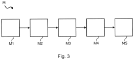
- Fig. 3 schematically illustrates a flowchart of stages of a method M for real-time in-line monitoring of industrial manufacturing processes.
- the method M may in particular be implemented in the manufacturing system 100 as illustrated in conjunction with Fig. 1 .
- the method M may employ a data acquisition system, such as the data acquisition system as explained in conjunction with Fig. 2
- one or more sensors 22a, 22b are placed within an active machining zone 23 of an industrial manufacturing machine 20.
- the industrial manufacturing machine 20 may be a composite manufacturing machine, such as a resin transfer molding machine having a mold cavity as active machining zone 23.
- the sensors 22a, 22b may be dielectric sensors that are employed as in-mold sensors which are placed in this mold cavity.
- the dielectric sensors 22a, 22b may then measure electrical responses of thermosetting resins in the mold cavity close to the sensor surface of the in-mold sensors.
- the measurement values are transmitted in a second stage M2 from the sensors 22a, 22b to a data acquisition system 10.
- the measurement values indicate physical properties of workpieces processed in the active machining zone 23 of the industrial manufacturing machine 20.
- the data acquisition system 10 transmits the received measurement values in a third stage M3 to cloud-based resources 40 via a cloud interface 3 of the data acquisition system 10 where statistical analysis on the transmitted measurement values from the sensors 22a, 22b may be performed. As a result of the performed statistical analysis, parameters may be transmitted back to the data acquisition system 10 where they are received in a fourth stage M4 via the cloud interface 3 at the data acquisition system 10.
- the data acquisition system 10 then transmits manufacturing control signals in a fifth stage M5 to a controller 21 of the industrial manufacturing machine 20.
- These manufacturing control signals are based on the parameters received from cloud-based resources 40 in order to optimize the operation of the industrial manufacturing machine 20 in real-time or at least near real-time.
Landscapes
- Engineering & Computer Science (AREA)
- Physics & Mathematics (AREA)
- General Physics & Mathematics (AREA)
- Chemical & Material Sciences (AREA)
- Health & Medical Sciences (AREA)
- Automation & Control Theory (AREA)
- Computer Networks & Wireless Communication (AREA)
- Signal Processing (AREA)
- Life Sciences & Earth Sciences (AREA)
- Electrochemistry (AREA)
- Pathology (AREA)
- Immunology (AREA)
- General Engineering & Computer Science (AREA)
- Manufacturing & Machinery (AREA)
- Quality & Reliability (AREA)
- General Health & Medical Sciences (AREA)
- Chemical Kinetics & Catalysis (AREA)
- Biochemistry (AREA)
- Analytical Chemistry (AREA)
- Artificial Intelligence (AREA)
- Software Systems (AREA)
- Computer Vision & Pattern Recognition (AREA)
- Evolutionary Computation (AREA)
- Medical Informatics (AREA)
- General Factory Administration (AREA)
- Injection Moulding Of Plastics Or The Like (AREA)
Description
- The present invention pertains to systems and methods for real-time in-line monitoring of industrial manufacturing processes involving molding in composite manufacturing machines.
- The present invention and the corresponding underlying problems will be explained in further detail in conjunction with resin transfer molding processes of high-tech composite components.
- Industrial manufacturing of composite components relies on reproducibly controlling curing behaviour of thermosetting materials since the properties of the final product heavily depend on the conditions of the curing process. Therefore, it is desirable to be able to closely monitor any such processes in real-time and in situ.
- Among the possible measurement methods are dielectric analysis (DEA), dynamic mechanical analysis, thermomechanical analysis, thermogravimetric analysis and differential thermal analysis. DEA and the other measurement methods allow for gaining insights in the curing patterns of composite materials, adhesives, coatings or thermosetting resin systems. By employing one or more of the possible measurement methods, multiple physical characteristics such as dielectric loss factor, ion conductivity, viscoelastic properties, dynamic moduli, glass transition temperatures, crystallization temperatures, sublimation temperatures, or ion viscosity may be determined by way of measurement of dipole polarization and ion migration patterns.
-
WO 2018/142977 A1 (SINTOKOGIO LTD [JP]) 9 August 2018 (2018-08-09) discloses a system and method for in-line monitoring industrial manufacturing processes involving molding machines. - The invention is defined by the system of
independent claim 1 and the method ofindependent claim 8. Optional aspects of the invention are provided in the dependent claims. - With the modules, systems and methods of the invention, it is advantageously possible to characterize composite parts in terms of production costs, component quality and material behaviour during production. Having greater insight into those parameters allows for optimizing curing cycle times, for adapting to process variations from batch to batch and for exactly reproducing certain process environments. As the structural health and integrity of the final components depends on the presence or absence of filling or cure-induced defects - which in turn depends on the filling and curing behaviour in situ - a quality control may be implemented by closely monitoring the curing processes in real-time and in-line with the manufacturing machine.
- Further, it is a particular advantage to employ cloud-based resources to analyse the measurement data generated in real-time and in situ. Such cloud-based resources may allow for pooling larger amounts of data from various manufacturing sites under different manufacturing conditions so that more information may be systematically extracted from the data. The employment of cloud-based resources in particular enables faster and more consistent creation of value by advanced data analytics in terms of predictability, quality control, pre-planning, optimization and/or robustness of manufacturing processes.
- A feedback mechanism from the cloud-based resources back to the data acquisition module enables the data acquisition module to beneficially influence the local behaviour of the industrial manufacturing processes taking into account knowledge and insights gained by the data analytics performed in the cloud-based resources. Advantageously, the local industrial manufacturing processes are thus optimized not only with regard to the instantaneous local manufacturing conditions, but also with regard to statistical data reflecting experiences and predictions of other (spatially or temporally) remote industrial manufacturing processes under similar conditions.
- The invention will be explained in greater detail with reference to exemplary embodiments depicted in the drawings as appended.
- The accompanying drawings are included to provide a further understanding of the present invention and are incorporated in and constitute a part of this specification. The drawings illustrate the embodiments of the present invention and together with the description serve to explain the principles of the invention. Other embodiments of the present invention and many of the intended advantages of the present invention will be readily appreciated as they become better understood by reference to the following detailed description. The elements of the drawings are not necessarily to scale relative to each other. Like reference numerals designate corresponding similar parts.
- Fig. 1
- schematically illustrates a system for real-time in-line monitoring of industrial manufacturing processes according to an exemplary embodiment of the invention;
- Fig. 2
- schematically illustrates a dielectric analysis data acquisition module according to an exemplary embodiment of the invention; and
- Fig. 3
- schematically illustrates a flowchart of stages of a method for real-time inline monitoring of industrial manufacturing processes according to an exemplary embodiment of the invention.
- In the figures, like reference numerals denote like or functionally like components, unless indicated otherwise.
- Although specific embodiments have been illustrated and described herein, it will be appreciated by those of ordinary skill in the art that a variety of alternate and/or equivalent implementations may be substituted for the specific embodiments shown, as long as they remain within the scope of the appended claims, which define the invention.
-
Fig. 1 schematically illustrates asystem 100 for real-time in-line monitoring of industrial manufacturing processes taking place in one or moreindustrial manufacturing machines 20, such as for example a resin transfer molding machine or in general a composite manufacturing machine. Theindustrial manufacturing machines 20 may be located in a manufacturing enterprise and may be functionally located on a machine level, exemplarily indicated with the reference sign "L1" inFig. 1 . Although there is only oneindustrial manufacturing machine 20 explicitly shown inFig. 1 , it should be clear that the manufacturing enterprise may employ more than oneindustrial manufacturing machine 20. Theindustrial manufacturing machine 20 may generally include anactive machining zone 23, in which a manufacturing process may take place. Theactive machining zone 23 may for example be a mold cavity - in the exemplary configuration as a resin transfer molding (RTM) machine -, but may include any other operational components as well. - The operation of the
industrial manufacturing machine 20 is generally controlled by amachine controller 21, which may for example be a programmable logic controller (PLC) or any other programmable industrial digital computer that is specifically adapted for controlling industrial manufacturing processes in a rugged environment. Themachine controller 21 is connected by a first databus B1 to adata acquisition system 10 by amachine interface 5. - Within the
active machining zone 23, one ormore sensors mold cavity 23 of an RTM machine. The sensors may for example be dielectric sensors such as interdigitated electrode sensors or plate electrode capacitance sensors. It may also be possible to employ additionally or alternatively other sensor types such as ultrasonic sensors, temperature sensors, dynamin mechanical sensors, stress gauges, differential thermal sensors or the like. There are only twosensors Fig. 1 , but it should be understood that more than two sensors of the same or different type, sensitivity and re-usability may be employed as well. - The
sensors sensor interface 4 of thedata acquisition system 10. The coupling may either be by wire, in which case thesensor interface 4 of thedata acquisition system 10 may include varioussensor interface ports 4a to 4n for any number of sensors. Alternatively or additionally, thesensors data acquisition system 10 wirelessly, for example via a radio-frequency data link. To that end, thedata acquisition system 10 may include one or morewireless communication adapters sensors wireless communication adapters - The machine level L1 also involves a
data acquisition system 10 for measurements that is shown in more detail inFig. 2 . It includes thesensor interface 4 coupled to asensor control device 8. By means of thesensor control device 8, the measurement conditions of thesensors industrial manufacturing machine 20. - A
module processor 1 as central computing unit within thedata acquisition system 10 is configured to receive dielectric measurement values from one ormore sensors sensor interface 4. Thedata acquisition system 10 additionally includes acloud interface 3 that is coupled to themodule processor 1 via acloud access device 7. Thecloud interface 3 may be connected to cloud-based resources as generally indicated with thereference sign 40 inFig. 1 , by any type of wireless, wired or mixed connection link C. - The term "cloud" and "cloud-based resources" within the meaning of the present disclosure is used to denote evolving networks of volatile arrangement that may communicate among each other via a common data network, such as the Internet. Those "cloud-based resources" may generally be located in a hierarchically upper data analysis level L3 and need not be physically located in the vicinity of the
manufacturing system 100 as such. "Cloud-based resources" may include any type of cloud service, such as application clouds, infrastructural clouds, client clouds, platform clouds, server clouds and other types of evolving networks. Clouds may enable any cloud participant to store and retrieve data in a distributed manner of various resources of the cloud. Clouds may perform various services to third party entities, such as platforms as a service (PaaS), software as a service (SaaS) or infrastructure as a service (laaS). While clouds may be available to third parties in general, operation of cloud-based resources may be provided for by a specific cloud service provider. By way of clouds, remote accesses to thedata acquisition module 10 or other local devices in themanufacturing system 10 may be made, for example byremote computing devices 50 for purposes of reconfiguration and/or maintenance. - Measurement values retrieved from the
sensors data acquisition system 10 may be processed in themodule processor 1 and may be transmitted by way of thecloud access device 7 to cloud-basedresources 40 via thecloud interface 3. The measurement values generally indicate physical properties of workpieces processed in theactive machining zone 23 of anindustrial manufacturing machine 20, such as for example dielectric permittivity, dielectric loss factor, ion conductivity, viscoelastic properties, dynamic moduli, glass transition temperatures, crystallization temperatures, sublimation temperatures, or ion viscosity. These physical parameters may be determined by way of measurement of dipole polarization and ion migration patterns. - In order to prepare the measurement values retrieved from the
sensors resources 40 or in other enterprise-based computing resources, themodule processor 1 may monitor or poll themachine controller 21 for trigger signals that indicating critical points in time in the received measurement values. For example, the opening or closing of themold cavity 23 of anRTM machine 20 may be such a critical point in time which may then be aligned with the measurement curve of the measurement values. Themodule processor 1 may particularly pre-process the received measurement values from thesensors resources 40 via thecloud interface 3 for a more thorough and valuable data analysis. - The
module processor 1 receives parameters from the cloud-basedresources 40 that include predictive or analytic information about manufacturing conditions, expected manufacturing results and similar. Those parameters may be taken into account by themodule processor 1 when transmitting manufacturing control signals to thecontroller 21 of theindustrial manufacturing machine 20 via themachine interface 5. Themodule processor 1 may analyse the parameters in order to optimally set manufacturing conditions in theindustrial manufacturing machine 20. To that end, thedata acquisition system 10 may include a machine control device 9 that is specifically dedicated to translate configuration signals into machine-readable instructions for transmission to themachine controller 21. - As illustrated in
Fig. 1 , there may be a control level generally indicated with the reference sign "L2" in which a human interface device (HID) 32 as well as amanufacturing enterprise server 32 as an enterprise-based computing resource may be located. The HID 32 may be connected to thedata acquisition system 10 via a common databus B2 to a human-machine interface 2 of thedata acquisition system 10. Themodule processor 1 may transmit any of the measurement values retrieved fromsensors resources 40 to the HID 32 for a human operator or user to review and evaluate manually. To that end, themodule processor 1 may be configured to pre-process the received measurement values from thesensors resources 40 before transmitting them to the HID 32. That way, the operator using the HID 32 may be able to get a clearer picture for purposes of quality control, process control and/or process monitoring. - It may also be possible for a human operator to directly control or supervise the operation of the
data acquisition system 10, for example by means of auser input panel 15 included in thedata acquisition system 10. Adata storage 14 in thedata acquisition system 10 coupled to themodule processor 1 may hold operating system and/or configuration data as well as temporary measurement value data for the human operator to work on using theuser input panel 15. - The common databus B2 may also be employed to couple two or more
data acquisition systems 10 among each other. Each of thedata acquisition systems 10 may then be able to transfer configuration data for acontroller 21 of anindustrial manufacturing machine 20 to otherdata acquisition systems 10 via the common databus B2. It may also be possible to transfer configuration data via an enterprise-based computing resource, such as a computer of an enterprise-wide network to which thedata acquisition systems 10 may be connected, for example themanufacture enterprise server 32. -
Fig. 3 schematically illustrates a flowchart of stages of a method M for real-time in-line monitoring of industrial manufacturing processes. The method M may in particular be implemented in themanufacturing system 100 as illustrated in conjunction withFig. 1 . The method M may employ a data acquisition system, such as the data acquisition system as explained in conjunction withFig. 2 - In a first stage M1, one or
more sensors active machining zone 23 of anindustrial manufacturing machine 20. For example, theindustrial manufacturing machine 20 may be a composite manufacturing machine, such as a resin transfer molding machine having a mold cavity asactive machining zone 23. Thesensors dielectric sensors - The measurement values are transmitted in a second stage M2 from the
sensors data acquisition system 10. The measurement values indicate physical properties of workpieces processed in theactive machining zone 23 of theindustrial manufacturing machine 20. - The
data acquisition system 10 transmits the received measurement values in a third stage M3 to cloud-basedresources 40 via acloud interface 3 of thedata acquisition system 10 where statistical analysis on the transmitted measurement values from thesensors data acquisition system 10 where they are received in a fourth stage M4 via thecloud interface 3 at thedata acquisition system 10. - The
data acquisition system 10 then transmits manufacturing control signals in a fifth stage M5 to acontroller 21 of theindustrial manufacturing machine 20. These manufacturing control signals are based on the parameters received from cloud-basedresources 40 in order to optimize the operation of theindustrial manufacturing machine 20 in real-time or at least near real-time. - In the foregoing detailed description, various features are grouped together in one or more examples or examples with the purpose of streamlining the disclosure. It is to be understood that the above description is intended to be illustrative, and not restrictive for the invention, which is defined and restricted by the appended claims.
-
- 1
- module processor
- 2
- human-machine interface
- 3
- cloud interface
- 4
- sensor interface
- 4a-n
- sensor interface ports
- 5
- machine interface
- 6
- user control device
- 7
- cloud access device
- 8
- sensor control device
- 9
- machine control device
- 10
- data acquisition system
- 11
- wireless communication adapter
- 12
- wireless communication adapter
- 13
- wireless communication adapter
- 14
- data storage
- 15
- user input panel
- 20
- industrial manufacturing machine
- 21
- machine controller
- 22a-b
- sensors
- 23
- active machining zone
- 31
- manufacturing enterprise server
- 32
- human interface device
- 40
- cloud-based resources
- 50
- remote computing device
- 100
- manufacturing system
- B1
- databus
- B2
- databus
- C
- connection link
- L1
- machine level
- L2
- control level
- L3
- data analysis level
- M
- method
- M1-5
- method stages
Claims (9)
- System (100) for real-time in-line monitoring industrial manufacturing processes, the system (100) comprising:one or more composite manufacturing machines (20), each having one or more mold cavities as active machining zones (23) and a controller (21);one or more in-mold sensors (22a; 22b) respectively placed in a respective mold cavity (23) of the composite manufacturing machines (20); andat least one data acquisition system (10) comprising:a sensor interface (4) connected to the one or more in-mold sensors (22a; 22b);a module processor (1) coupled to the sensor interface (4) and configured to receive measurement values from the one or more in-mold sensors (22a; 22b) connected to the sensor interface (4), the measurement values indicating physical properties of workpieces processed in the mold cavities (23) of the composite manufacturing machines (20);a cloud interface (3) coupled to the module processor (1), the cloud interface (3) being configured to connect to cloud-based resources (40); anda machine interface (5) coupled to the module processor (1), the machine interface (5) being configured to connect to the controllers (21) of the composite manufacturing machine (20),wherein the module processor (1) is configured to transmit the received measurement values from the one or more sensors (22a; 22b) to cloud-based resources (40) via the cloud interface (3) and to transmit manufacturing control signals to the controllers (21) of the composite manufacturing machine (20) via the machine interface (5), the manufacturing control signals being based on parameters received from cloud-based resources (40) via the cloud interface (3), andwherein the controllers (21) of the composite manufacturing machines (20) are configured to control the operation of the one or more composite manufacturing machines (20) based on the manufacturing control signals received from the module processor (1) of the data acquisition system (10);wherein the system (100) comprises at least two data acquisition systems (10) coupled to each other via a common databus (B2) or via an enterprise-based computing resource.
- System (100) according to claim 1, the data acquisition system (10)further comprising:
a human-machine interface (2) configured to connect to a human interface device (32) via a databus (B2), the module processor (1) being configured to transmit the received measurement values from the one or more in-mold sensors (22a; 22b) to the human interface device (32) via the human-machine interface (2). - System (100) according to claim 2, wherein the module processor (1) is configured to pre-process the received measurement values from the one or more in-mold sensors (22a; 22b) based on parameters received from cloud-based resources (40) via the cloud interface (3) or based on enterprise-based resources before transmitting them to the human interface device (32).
- System (100) according to one of the preceding claims, wherein the module processor (1) is configured to receive a trigger signal from the controller (21) of the composite manufacturing machine (20) via the machine interface (5), the trigger signal indicating a critical point in time in the dielectric measurement values from the one or more in-mold sensors (22a; 22b).
- System (100) according to claim 4, wherein the module processor (1) is configured to pre-process the received measurement values from the one or more in-mold sensors (22a; 22b) on the basis of the critical point in time indicated by the received trigger signal before transmitting the received measurement values to cloud-based resources (40) via the cloud interface (3) or to enterprise-based resources.
- System (100) according to any one of the preceding claims, wherein a first one of the at least two data acquisition systems (10) is configured to transfer configuration data for one of the controllers (21) of the composite manufacturing machines (20) to a second one of the at least two data acquisition systems (10) via the common databus (B2).
- System (100) according to one of the claims 1 to 6, wherein the at least one data acquisition system (10) includes a sensor control device (8) configured to modify the measurement conditions of the one or more in-mold sensors (22a; 22b) during a manufacturing process of the composite manufacturing machines (20).
- Method (M) for real-time in-line monitoring of industrial manufacturing processes by a system (100) for real-time in-line monitoring of industrial manufacturing processes, the method (M) comprising:placing (M1) one or more in-mold sensors (22a; 22b) within mold cavities as active machining zones (23) of composite manufacturing machines (20) of the system (100);transmitting (M2) measurement values from the one or more in-mold sensors (22a; 22b) via a sensor interface (4) to a data acquisition system (10) of the system (100), the measurement values indicating physical properties of workpieces processed in the mold cavities (23) of the composite manufacturing machines (20);transmitting (M3), by the data acquisition system (10), the received measurement values from the one or more in-mold sensors (22a; 22b) to cloud-based resources (40) via a cloud interface (3) of the data acquisition system (10);receiving (M4) parameters from cloud-based resources (40) via the cloud interface (3) at the data acquisition system (10);transmitting (M5), by a module processor (1) of the data acquisition system(10), manufacturing control signals to respective controllers (21) of the composite manufacturing machines (20) via a machine interface (5), the manufacturing control signals being based on the parameters received from cloud-based resources (40) via the cloud interface (3) of the data acquisition system (10); andcontrolling, by the controllers (21) of the composite manufacturing machines (20), the operation of the one or more composite manufacturing machines (20) based on the manufacturing control signals received from the module processor (1) of the data acquisition system;wherein the system (100) comprises at least two data acquisition systems (10) coupled to each other via a common databus (B2) or via an enterprise-based computing resource.
- Method (M) according to claim 8, wherein the cloud-based resources (40) perform statistical analysis on the transmitted dielectric measurement values from the one or more in-mold sensors (22a; 22b) and output the parameters on the basis of the result of the performed statistical analysis.
Applications Claiming Priority (1)
| Application Number | Priority Date | Filing Date | Title |
|---|---|---|---|
| DE102019121281.2A DE102019121281A1 (en) | 2019-08-07 | 2019-08-07 | Data acquisition system, system and method for real-time in-line monitoring of industrial manufacturing processes |
Publications (3)
| Publication Number | Publication Date |
|---|---|
| EP3786731A1 EP3786731A1 (en) | 2021-03-03 |
| EP3786731C0 EP3786731C0 (en) | 2024-08-14 |
| EP3786731B1 true EP3786731B1 (en) | 2024-08-14 |
Family
ID=70857018
Family Applications (1)
| Application Number | Title | Priority Date | Filing Date |
|---|---|---|---|
| EP20176412.3A Active EP3786731B1 (en) | 2019-08-07 | 2020-05-26 | System and method for real-time in-line monitoring of industrial production processes |
Country Status (6)
| Country | Link |
|---|---|
| US (1) | US11493907B2 (en) |
| EP (1) | EP3786731B1 (en) |
| JP (1) | JP6878655B2 (en) |
| CN (1) | CN112351057A (en) |
| DE (1) | DE102019121281A1 (en) |
| ES (1) | ES2988044T3 (en) |
Families Citing this family (6)
| Publication number | Priority date | Publication date | Assignee | Title |
|---|---|---|---|---|
| EP4084416B1 (en) * | 2021-04-30 | 2025-10-15 | ABB Schweiz AG | Monitoring a communication system that is used for control and/or surveillance of an industrial process |
| CN113868484B (en) * | 2021-08-30 | 2023-03-21 | 北京北方华创微电子装备有限公司 | Data acquisition method, device and system for semiconductor process equipment |
| US20230206040A1 (en) * | 2021-12-23 | 2023-06-29 | International Business Machines Corporation | Collaborative monitoring of industrial systems |
| CN115356994B (en) * | 2022-08-10 | 2024-12-06 | 机械工业仪器仪表综合技术经济研究所 | Integrity management system for instrumentation and control equipment of petroleum refining units based on industrial Internet |
| JP7306550B1 (en) | 2022-09-21 | 2023-07-11 | 凸版印刷株式会社 | Production control system, production control method and program |
| CN120009359B (en) * | 2025-04-21 | 2025-07-04 | 成都秦川物联网科技股份有限公司 | Workpiece quality detection method, system, equipment and medium based on industrial Internet of things |
Family Cites Families (22)
| Publication number | Priority date | Publication date | Assignee | Title |
|---|---|---|---|---|
| JP2756077B2 (en) * | 1993-12-27 | 1998-05-25 | 東芝機械株式会社 | Automatic setting method of injection molding speed condition of injection molding machine |
| WO2000034796A1 (en) * | 1998-12-10 | 2000-06-15 | University Of Maryland | Scanning single electron transistor microscope for imaging ambient temperature objects |
| DE10152765B4 (en) * | 2001-07-13 | 2015-11-12 | Siemens Aktiengesellschaft | A method for electronically providing services to machines via a data communication link |
| JP2004164635A (en) * | 2002-10-25 | 2004-06-10 | N System:Kk | Monitor device for production management |
| US7110918B2 (en) * | 2003-11-05 | 2006-09-19 | Shoplogix Inc. | Self-contained system and method for remotely monitoring machines |
| EP2660667B1 (en) * | 2012-05-04 | 2021-11-10 | Rockwell Automation Technologies, Inc. | Cloud gateway for industrial automation information and control systems |
| US9467500B2 (en) * | 2012-08-09 | 2016-10-11 | Rockwell Automation Technologies, Inc. | Remote industrial monitoring using a cloud infrastructure |
| US20150106912A1 (en) * | 2013-10-16 | 2015-04-16 | Milacron Llc | Remote machine monitoring systems and services |
| GB2521376A (en) * | 2013-12-17 | 2015-06-24 | Intellisense Io Ltd | System and method for securely managing data of industrial control systems |
| WO2016065493A1 (en) * | 2014-10-31 | 2016-05-06 | Cloudbased Industry 4.0 Technologies Ag | A client device for data acquisition and pre-processing of process-related mass data from at least one cnc machine or industrial robot |
| US20180052451A1 (en) * | 2016-08-19 | 2018-02-22 | Rockwell Automation Technologies, Inc. | Remote industrial automation site operation in a cloud platform |
| CN206060825U (en) * | 2016-09-09 | 2017-03-29 | 深圳市智物联网络有限公司 | A kind of device for realizing that multi-joint net mode accesses Internet of Things cloud platform |
| WO2018101848A1 (en) * | 2016-11-29 | 2018-06-07 | Coolfarm S.A. | Predictive dynamic cloud based system for environmental sensing and actuation and respective method of operation |
| TW201832900A (en) * | 2016-12-01 | 2018-09-16 | 日商新東工業股份有限公司 | Information display system for casting facility |
| US20180164764A1 (en) * | 2016-12-12 | 2018-06-14 | General Electric Company | Apparatus and Method for Analysis of Machine Performance |
| JP6624100B2 (en) * | 2017-02-03 | 2019-12-25 | 新東工業株式会社 | A system that detects the cause of abnormalities in multiple devices that make up a casting facility |
| DE102017202360A1 (en) * | 2017-02-14 | 2018-08-16 | Deckel Maho Pfronten Gmbh | DATA INTERFACE DEVICE FOR USE IN A NUMERICALLY CONTROLLED TOOL MACHINE |
| CN206855951U (en) * | 2017-04-28 | 2018-01-09 | 恩格尔注塑机械(常州)有限公司 | The monitoring system of injection machine and the hydraulic pressure oil quality for monitoring injection machine |
| US10989680B2 (en) * | 2017-05-25 | 2021-04-27 | Board or Regents, The University of Texas Systems | Systems and methods for assessing the quality of adhesive bonds |
| CN207304620U (en) * | 2017-09-08 | 2018-05-01 | 深圳市智物联网络有限公司 | Industrial equipment revertive control system based on Internet of Things |
| WO2019182952A1 (en) * | 2018-03-20 | 2019-09-26 | Tokyo Electron Limited | Self-aware and correcting heterogenous platform incorporating integrated semiconductor processing modules and method for using same |
| CN109342514A (en) * | 2018-09-04 | 2019-02-15 | 东莞弗兰德通信科技有限公司 | Dielectric constant measuring method and device for dielectric plastics |
-
2019
- 2019-08-07 DE DE102019121281.2A patent/DE102019121281A1/en active Pending
-
2020
- 2020-05-25 JP JP2020090900A patent/JP6878655B2/en active Active
- 2020-05-26 ES ES20176412T patent/ES2988044T3/en active Active
- 2020-05-26 EP EP20176412.3A patent/EP3786731B1/en active Active
- 2020-05-29 US US16/886,866 patent/US11493907B2/en active Active
- 2020-07-27 CN CN202010740792.1A patent/CN112351057A/en active Pending
Also Published As
| Publication number | Publication date |
|---|---|
| EP3786731A1 (en) | 2021-03-03 |
| CN112351057A (en) | 2021-02-09 |
| US20210041857A1 (en) | 2021-02-11 |
| US11493907B2 (en) | 2022-11-08 |
| JP6878655B2 (en) | 2021-05-26 |
| JP2021026758A (en) | 2021-02-22 |
| EP3786731C0 (en) | 2024-08-14 |
| DE102019121281A1 (en) | 2021-02-11 |
| ES2988044T3 (en) | 2024-11-19 |
Similar Documents
| Publication | Publication Date | Title |
|---|---|---|
| US11493907B2 (en) | Data acquisition system, system and method for real-time in-line monitoring of industrial manufacturing processes | |
| US20230359185A1 (en) | Publish/subscribe protocol for real-time process control | |
| KR100932563B1 (en) | Versatile Semiconductor Manufacturing Controllers with Statistically Repeatable Response Times | |
| CN108139742A (en) | It determines to debug the device systems label of the part of process control loop disconnected | |
| KR102137642B1 (en) | Cps system for smart factories | |
| CN110913362B (en) | Method and device for realizing wireless signal test through client and test equipment | |
| CN112805424B (en) | Spinning machine and method for operating the spinning machine | |
| CN113359642A (en) | Multi-brand fusion dyeing and finishing control method, device, system and processor | |
| KR101716582B1 (en) | Integrated processing system based on data distribution service and operating method thereof | |
| US20180372788A1 (en) | Universal terminals transmitter supporting flexible connection of rtd sensor | |
| US20170012991A1 (en) | Method and system for wirelessly communicating with process machinery using a remote electronic device | |
| US10637841B2 (en) | Apparatus and method for using a security appliance with IEC 61131-3 | |
| US12231554B2 (en) | Method for connecting a field device to a cloud | |
| US9892011B2 (en) | Apparatus and method for autodetection of HART devices over PROFIBUS | |
| CN115997376A (en) | plant room communication | |
| Hoppe | Forerunner to Industry 4.0 and the Internet of Things | |
| Behrens et al. | A Versatile IoT-Approach to Process Data Acquisition | |
| CN110901001A (en) | Molded article manufacturing system and molded article takeout machine | |
| US12587583B2 (en) | Embedded systems, and methods, having sensor signal interfaces for improving maintenance and data acquisition in manufacturing operations | |
| EP3419199B1 (en) | Virtual wireless devices for industrial wireless sensor networks | |
| WO2019128333A1 (en) | Method, apparatus and system for acquiring fully automatic impact test result | |
| Ventura et al. | Performance for interoperability between raspberry pi and esp8266 with a plc in a node-red server for iiot | |
| Wei et al. | Research on Data Acquisition Scheme in PHM System Based on Data Driven | |
| EP3968604A1 (en) | An iot platform, an apparatus and method of operating the iot platform | |
| KR20160144704A (en) | System for controlling semiconductor manufacturing equipments |
Legal Events
| Date | Code | Title | Description |
|---|---|---|---|
| PUAI | Public reference made under article 153(3) epc to a published international application that has entered the european phase |
Free format text: ORIGINAL CODE: 0009012 |
|
| STAA | Information on the status of an ep patent application or granted ep patent |
Free format text: STATUS: THE APPLICATION HAS BEEN PUBLISHED |
|
| PUAB | Information related to the publication of an a document modified or deleted |
Free format text: ORIGINAL CODE: 0009199EPPU |
|
| PUAI | Public reference made under article 153(3) epc to a published international application that has entered the european phase |
Free format text: ORIGINAL CODE: 0009012 |
|
| AK | Designated contracting states |
Kind code of ref document: A1 Designated state(s): AL AT BE BG CH CY CZ DE DK EE ES FI FR GB GR HR HU IE IS IT LI LT LU LV MC MK MT NL NO PL PT RO RS SE SI SK SM TR |
|
| AX | Request for extension of the european patent |
Extension state: BA ME |
|
| STAA | Information on the status of an ep patent application or granted ep patent |
Free format text: STATUS: REQUEST FOR EXAMINATION WAS MADE |
|
| 17P | Request for examination filed |
Effective date: 20210903 |
|
| RBV | Designated contracting states (corrected) |
Designated state(s): AL AT BE BG CH CY CZ DE DK EE ES FI FR GB GR HR HU IE IS IT LI LT LU LV MC MK MT NL NO PL PT RO RS SE SI SK SM TR |
|
| STAA | Information on the status of an ep patent application or granted ep patent |
Free format text: STATUS: EXAMINATION IS IN PROGRESS |
|
| RAP1 | Party data changed (applicant data changed or rights of an application transferred) |
Owner name: NETZSCH PROCESS INTELLIGENCE GMBH |
|
| 17Q | First examination report despatched |
Effective date: 20220413 |
|
| GRAP | Despatch of communication of intention to grant a patent |
Free format text: ORIGINAL CODE: EPIDOSNIGR1 |
|
| STAA | Information on the status of an ep patent application or granted ep patent |
Free format text: STATUS: GRANT OF PATENT IS INTENDED |
|
| RIC1 | Information provided on ipc code assigned before grant |
Ipc: B29C 70/48 20060101ALN20240229BHEP Ipc: G05B 13/02 20060101AFI20240229BHEP |
|
| INTG | Intention to grant announced |
Effective date: 20240326 |
|
| GRAS | Grant fee paid |
Free format text: ORIGINAL CODE: EPIDOSNIGR3 |
|
| GRAA | (expected) grant |
Free format text: ORIGINAL CODE: 0009210 |
|
| STAA | Information on the status of an ep patent application or granted ep patent |
Free format text: STATUS: THE PATENT HAS BEEN GRANTED |
|
| AK | Designated contracting states |
Kind code of ref document: B1 Designated state(s): AL AT BE BG CH CY CZ DE DK EE ES FI FR GB GR HR HU IE IS IT LI LT LU LV MC MK MT NL NO PL PT RO RS SE SI SK SM TR |
|
| REG | Reference to a national code |
Ref country code: GB Ref legal event code: FG4D |
|
| REG | Reference to a national code |
Ref country code: CH Ref legal event code: EP |
|
| REG | Reference to a national code |
Ref country code: DE Ref legal event code: R096 Ref document number: 602020035626 Country of ref document: DE |
|
| REG | Reference to a national code |
Ref country code: IE Ref legal event code: FG4D |
|
| U01 | Request for unitary effect filed |
Effective date: 20240910 |
|
| U07 | Unitary effect registered |
Designated state(s): AT BE BG DE DK EE FI FR IT LT LU LV MT NL PT RO SE SI Effective date: 20240926 |
|
| REG | Reference to a national code |
Ref country code: ES Ref legal event code: FG2A Ref document number: 2988044 Country of ref document: ES Kind code of ref document: T3 Effective date: 20241119 |
|
| PG25 | Lapsed in a contracting state [announced via postgrant information from national office to epo] |
Ref country code: NO Free format text: LAPSE BECAUSE OF FAILURE TO SUBMIT A TRANSLATION OF THE DESCRIPTION OR TO PAY THE FEE WITHIN THE PRESCRIBED TIME-LIMIT Effective date: 20241114 |
|
| PG25 | Lapsed in a contracting state [announced via postgrant information from national office to epo] |
Ref country code: GR Free format text: LAPSE BECAUSE OF FAILURE TO SUBMIT A TRANSLATION OF THE DESCRIPTION OR TO PAY THE FEE WITHIN THE PRESCRIBED TIME-LIMIT Effective date: 20241115 Ref country code: PL Free format text: LAPSE BECAUSE OF FAILURE TO SUBMIT A TRANSLATION OF THE DESCRIPTION OR TO PAY THE FEE WITHIN THE PRESCRIBED TIME-LIMIT Effective date: 20240814 |
|
| PG25 | Lapsed in a contracting state [announced via postgrant information from national office to epo] |
Ref country code: IS Free format text: LAPSE BECAUSE OF FAILURE TO SUBMIT A TRANSLATION OF THE DESCRIPTION OR TO PAY THE FEE WITHIN THE PRESCRIBED TIME-LIMIT Effective date: 20241214 |
|
| PG25 | Lapsed in a contracting state [announced via postgrant information from national office to epo] |
Ref country code: HR Free format text: LAPSE BECAUSE OF FAILURE TO SUBMIT A TRANSLATION OF THE DESCRIPTION OR TO PAY THE FEE WITHIN THE PRESCRIBED TIME-LIMIT Effective date: 20240814 |
|
| PG25 | Lapsed in a contracting state [announced via postgrant information from national office to epo] |
Ref country code: RS Free format text: LAPSE BECAUSE OF FAILURE TO SUBMIT A TRANSLATION OF THE DESCRIPTION OR TO PAY THE FEE WITHIN THE PRESCRIBED TIME-LIMIT Effective date: 20241114 |
|
| PG25 | Lapsed in a contracting state [announced via postgrant information from national office to epo] |
Ref country code: RS Free format text: LAPSE BECAUSE OF FAILURE TO SUBMIT A TRANSLATION OF THE DESCRIPTION OR TO PAY THE FEE WITHIN THE PRESCRIBED TIME-LIMIT Effective date: 20241114 Ref country code: PL Free format text: LAPSE BECAUSE OF FAILURE TO SUBMIT A TRANSLATION OF THE DESCRIPTION OR TO PAY THE FEE WITHIN THE PRESCRIBED TIME-LIMIT Effective date: 20240814 Ref country code: NO Free format text: LAPSE BECAUSE OF FAILURE TO SUBMIT A TRANSLATION OF THE DESCRIPTION OR TO PAY THE FEE WITHIN THE PRESCRIBED TIME-LIMIT Effective date: 20241114 Ref country code: IS Free format text: LAPSE BECAUSE OF FAILURE TO SUBMIT A TRANSLATION OF THE DESCRIPTION OR TO PAY THE FEE WITHIN THE PRESCRIBED TIME-LIMIT Effective date: 20241214 Ref country code: HR Free format text: LAPSE BECAUSE OF FAILURE TO SUBMIT A TRANSLATION OF THE DESCRIPTION OR TO PAY THE FEE WITHIN THE PRESCRIBED TIME-LIMIT Effective date: 20240814 Ref country code: GR Free format text: LAPSE BECAUSE OF FAILURE TO SUBMIT A TRANSLATION OF THE DESCRIPTION OR TO PAY THE FEE WITHIN THE PRESCRIBED TIME-LIMIT Effective date: 20241115 |
|
| PG25 | Lapsed in a contracting state [announced via postgrant information from national office to epo] |
Ref country code: SM Free format text: LAPSE BECAUSE OF FAILURE TO SUBMIT A TRANSLATION OF THE DESCRIPTION OR TO PAY THE FEE WITHIN THE PRESCRIBED TIME-LIMIT Effective date: 20240814 |
|
| PG25 | Lapsed in a contracting state [announced via postgrant information from national office to epo] |
Ref country code: CZ Free format text: LAPSE BECAUSE OF FAILURE TO SUBMIT A TRANSLATION OF THE DESCRIPTION OR TO PAY THE FEE WITHIN THE PRESCRIBED TIME-LIMIT Effective date: 20240814 |
|
| PG25 | Lapsed in a contracting state [announced via postgrant information from national office to epo] |
Ref country code: SK Free format text: LAPSE BECAUSE OF FAILURE TO SUBMIT A TRANSLATION OF THE DESCRIPTION OR TO PAY THE FEE WITHIN THE PRESCRIBED TIME-LIMIT Effective date: 20240814 |
|
| PLBE | No opposition filed within time limit |
Free format text: ORIGINAL CODE: 0009261 |
|
| STAA | Information on the status of an ep patent application or granted ep patent |
Free format text: STATUS: NO OPPOSITION FILED WITHIN TIME LIMIT |
|
| U20 | Renewal fee for the european patent with unitary effect paid |
Year of fee payment: 6 Effective date: 20250520 |
|
| PGFP | Annual fee paid to national office [announced via postgrant information from national office to epo] |
Ref country code: GB Payment date: 20250524 Year of fee payment: 6 Ref country code: ES Payment date: 20250602 Year of fee payment: 6 |
|
| 26N | No opposition filed |
Effective date: 20250515 |
|
| PGFP | Annual fee paid to national office [announced via postgrant information from national office to epo] |
Ref country code: CH Payment date: 20250601 Year of fee payment: 6 |
|
| PG25 | Lapsed in a contracting state [announced via postgrant information from national office to epo] |
Ref country code: MC Free format text: LAPSE BECAUSE OF FAILURE TO SUBMIT A TRANSLATION OF THE DESCRIPTION OR TO PAY THE FEE WITHIN THE PRESCRIBED TIME-LIMIT Effective date: 20240814 |
|
| PG25 | Lapsed in a contracting state [announced via postgrant information from national office to epo] |
Ref country code: IE Free format text: LAPSE BECAUSE OF NON-PAYMENT OF DUE FEES Effective date: 20250526 |