EP3786648B1 - Anschlusssensoranordnung - Google Patents
Anschlusssensoranordnung Download PDFInfo
- Publication number
- EP3786648B1 EP3786648B1 EP20193381.9A EP20193381A EP3786648B1 EP 3786648 B1 EP3786648 B1 EP 3786648B1 EP 20193381 A EP20193381 A EP 20193381A EP 3786648 B1 EP3786648 B1 EP 3786648B1
- Authority
- EP
- European Patent Office
- Prior art keywords
- sensor
- terminal
- electrical
- conducting probe
- values
- Prior art date
- Legal status (The legal status is an assumption and is not a legal conclusion. Google has not performed a legal analysis and makes no representation as to the accuracy of the status listed.)
- Active
Links
Images



Classifications
-
- G—PHYSICS
- G01—MEASURING; TESTING
- G01R—MEASURING ELECTRIC VARIABLES; MEASURING MAGNETIC VARIABLES
- G01R19/00—Arrangements for measuring currents or voltages or for indicating presence or sign thereof
- G01R19/165—Indicating that current or voltage is either above or below a predetermined value or within or outside a predetermined range of values
- G01R19/16533—Indicating that current or voltage is either above or below a predetermined value or within or outside a predetermined range of values characterised by the application
- G01R19/16538—Indicating that current or voltage is either above or below a predetermined value or within or outside a predetermined range of values characterised by the application in AC or DC supplies
-
- G—PHYSICS
- G01—MEASURING; TESTING
- G01K—MEASURING TEMPERATURE; MEASURING QUANTITY OF HEAT; THERMALLY-SENSITIVE ELEMENTS NOT OTHERWISE PROVIDED FOR
- G01K13/00—Thermometers specially adapted for specific purposes
-
- G—PHYSICS
- G01—MEASURING; TESTING
- G01R—MEASURING ELECTRIC VARIABLES; MEASURING MAGNETIC VARIABLES
- G01R1/00—Details of instruments or arrangements of the types included in groups G01R5/00 - G01R13/00 and G01R31/00
- G01R1/02—General constructional details
- G01R1/06—Measuring leads; Measuring probes
- G01R1/067—Measuring probes
-
- G—PHYSICS
- G01—MEASURING; TESTING
- G01R—MEASURING ELECTRIC VARIABLES; MEASURING MAGNETIC VARIABLES
- G01R1/00—Details of instruments or arrangements of the types included in groups G01R5/00 - G01R13/00 and G01R31/00
- G01R1/02—General constructional details
- G01R1/06—Measuring leads; Measuring probes
- G01R1/067—Measuring probes
- G01R1/06794—Devices for sensing when probes are in contact, or in position to contact, with measured object
-
- G—PHYSICS
- G01—MEASURING; TESTING
- G01R—MEASURING ELECTRIC VARIABLES; MEASURING MAGNETIC VARIABLES
- G01R1/00—Details of instruments or arrangements of the types included in groups G01R5/00 - G01R13/00 and G01R31/00
- G01R1/02—General constructional details
- G01R1/06—Measuring leads; Measuring probes
- G01R1/067—Measuring probes
- G01R1/073—Multiple probes
- G01R1/07307—Multiple probes with individual probe elements, e.g. needles, cantilever beams or bump contacts, fixed in relation to each other, e.g. bed of nails fixture or probe card
-
- G—PHYSICS
- G01—MEASURING; TESTING
- G01R—MEASURING ELECTRIC VARIABLES; MEASURING MAGNETIC VARIABLES
- G01R15/00—Details of measuring arrangements of the types provided for in groups G01R17/00 - G01R29/00, G01R33/00 - G01R33/26 or G01R35/00
- G01R15/12—Circuits for multi-testers, i.e. multimeters, e.g. for measuring voltage, current, or impedance at will
- G01R15/125—Circuits for multi-testers, i.e. multimeters, e.g. for measuring voltage, current, or impedance at will for digital multimeters
-
- G—PHYSICS
- G01—MEASURING; TESTING
- G01R—MEASURING ELECTRIC VARIABLES; MEASURING MAGNETIC VARIABLES
- G01R19/00—Arrangements for measuring currents or voltages or for indicating presence or sign thereof
-
- G—PHYSICS
- G01—MEASURING; TESTING
- G01R—MEASURING ELECTRIC VARIABLES; MEASURING MAGNETIC VARIABLES
- G01R19/00—Arrangements for measuring currents or voltages or for indicating presence or sign thereof
- G01R19/25—Arrangements for measuring currents or voltages or for indicating presence or sign thereof using digital measurement techniques
- G01R19/2503—Arrangements for measuring currents or voltages or for indicating presence or sign thereof using digital measurement techniques for measuring voltage only, e.g. digital volt meters (DVM's)
-
- G—PHYSICS
- G01—MEASURING; TESTING
- G01R—MEASURING ELECTRIC VARIABLES; MEASURING MAGNETIC VARIABLES
- G01R19/00—Arrangements for measuring currents or voltages or for indicating presence or sign thereof
- G01R19/25—Arrangements for measuring currents or voltages or for indicating presence or sign thereof using digital measurement techniques
- G01R19/2513—Arrangements for monitoring electric power systems, e.g. power lines or loads; Logging
-
- G—PHYSICS
- G01—MEASURING; TESTING
- G01R—MEASURING ELECTRIC VARIABLES; MEASURING MAGNETIC VARIABLES
- G01R19/00—Arrangements for measuring currents or voltages or for indicating presence or sign thereof
- G01R19/32—Compensating for temperature change
-
- G—PHYSICS
- G01—MEASURING; TESTING
- G01R—MEASURING ELECTRIC VARIABLES; MEASURING MAGNETIC VARIABLES
- G01R31/00—Arrangements for testing electric properties; Arrangements for locating electric faults; Arrangements for electrical testing characterised by what is being tested not provided for elsewhere
- G01R31/327—Testing of circuit interrupters, switches or circuit-breakers
- G01R31/3271—Testing of circuit interrupters, switches or circuit-breakers of high voltage or medium voltage devices
-
- G—PHYSICS
- G01—MEASURING; TESTING
- G01R—MEASURING ELECTRIC VARIABLES; MEASURING MAGNETIC VARIABLES
- G01R31/00—Arrangements for testing electric properties; Arrangements for locating electric faults; Arrangements for electrical testing characterised by what is being tested not provided for elsewhere
- G01R31/40—Testing power supplies
-
- G—PHYSICS
- G01—MEASURING; TESTING
- G01R—MEASURING ELECTRIC VARIABLES; MEASURING MAGNETIC VARIABLES
- G01R31/00—Arrangements for testing electric properties; Arrangements for locating electric faults; Arrangements for electrical testing characterised by what is being tested not provided for elsewhere
- G01R31/50—Testing of electric apparatus, lines, cables or components for short-circuits, continuity, leakage current or incorrect line connections
-
- H—ELECTRICITY
- H01—ELECTRIC ELEMENTS
- H01R—ELECTRICALLY-CONDUCTIVE CONNECTIONS; STRUCTURAL ASSOCIATIONS OF A PLURALITY OF MUTUALLY-INSULATED ELECTRICAL CONNECTING ELEMENTS; COUPLING DEVICES; CURRENT COLLECTORS
- H01R11/00—Individual connecting elements providing two or more spaced connecting locations for conductive members which are, or may be, thereby interconnected, e.g. end pieces for wires or cables supported by the wire or cable and having means for facilitating electrical connection to some other wire, terminal, or conductive member, blocks of binding posts
- H01R11/11—End pieces or tapping pieces for wires, supported by the wire and for facilitating electrical connection to some other wire, terminal or conductive member
-
- H—ELECTRICITY
- H02—GENERATION; CONVERSION OR DISTRIBUTION OF ELECTRIC POWER
- H02G—INSTALLATION OF ELECTRIC CABLES OR LINES, OR OF COMBINED OPTICAL AND ELECTRIC CABLES OR LINES
- H02G3/00—Installations of electric cables or lines or protective tubing therefor in or on buildings, equivalent structures or vehicles
- H02G3/02—Details
- H02G3/08—Distribution boxes; Connection or junction boxes
- H02G3/16—Distribution boxes; Connection or junction boxes structurally associated with support for line-connecting terminals within the box
-
- H—ELECTRICITY
- H01—ELECTRIC ELEMENTS
- H01R—ELECTRICALLY-CONDUCTIVE CONNECTIONS; STRUCTURAL ASSOCIATIONS OF A PLURALITY OF MUTUALLY-INSULATED ELECTRICAL CONNECTING ELEMENTS; COUPLING DEVICES; CURRENT COLLECTORS
- H01R13/00—Details of coupling devices of the kinds covered by groups H01R12/70 or H01R24/00 - H01R33/00
- H01R13/66—Structural association with built-in electrical component
- H01R13/665—Structural association with built-in electrical component with built-in electronic circuit
- H01R13/6683—Structural association with built-in electrical component with built-in electronic circuit with built-in sensor
-
- H—ELECTRICITY
- H01—ELECTRIC ELEMENTS
- H01R—ELECTRICALLY-CONDUCTIVE CONNECTIONS; STRUCTURAL ASSOCIATIONS OF A PLURALITY OF MUTUALLY-INSULATED ELECTRICAL CONNECTING ELEMENTS; COUPLING DEVICES; CURRENT COLLECTORS
- H01R9/00—Structural associations of a plurality of mutually-insulated electrical connecting elements, e.g. terminal strips or terminal blocks; Terminals or binding posts mounted upon a base or in a case; Bases therefor
- H01R9/22—Bases, e.g. strip, block, panel
- H01R9/24—Terminal blocks
Definitions
- the present disclosure relates to the field of electronic components and devices containing electronic components.
- the terminals of power devices may have low contact resistance to, for example, limit power losses and/or reduce heat generation.
- the terminal size/type and wire gauge may be determined by the maximum current rating. For low currents, thin wires and small terminals may be used, and for high currents, large wires and terminals may be used. Units are abbreviated here and throughout the disclosure as millimeter (mm), millimeter square (mm 2 ), 1000 circular mils (kcmil), meter (m), milli-ohm (m ⁇ ), degrees centigrade (°C), and amperes (A).
- a wire gauge of 8 American Wire Gauge may have a maximum current rating of 20 A (when at 6 meters length) and may be connected to a terminal block, such as WAGO ® model 284-101.
- a wire gauge of 6 AWG may have a maximum current rating of 70 A (when up to a length of 3 meters) and use a terminal having at least as a 16 mm 2 wire cross section capability, such as Weidmüller ® type WPE 10 part number 1010300000.
- Wire gauges may range from very small sizes to very large size, where some of the sizes are listed in the following table: TABLE 1 AWG Diameter Area Copper wire Resistance / length Ampacity, at 20 °C insulation material temperature rating 60 °C 75 °C 90 °C (mm) (kcmil) (mm 2 ) (m ⁇ /m) (A) 0000 (4/0) 11.684 212 107 0.1608 195 230 260 000 (3/0) 10.405 168 85 0.2028 165 200 225 00 (2/0) 9.266 133 67.4 0.2557 145 175 195 0 (1/0) 8.251 106 53.5 0.3224 125 150 170 1 7.348 83.7 42.4 0.4066 110 130 145 2 6.544 66.4 33.6 0.5127 95 115 130 3 5.827 52.6 26.7 0.6465 85 100 115 4 5.189 41.7 21.2 0.8152 70 85 95 5 4.621 33.1 16.8 1.028 6 4.115 26.3 13.3 1.296
- terminal blocks attached to a support may be used.
- the terminal blocks comprise multiple terminals arranged in tiers or along rows, and may be mechanically coupled to a support, such as a rail, a printed circuit board, or an enclosure.
- a support such as a rail, a printed circuit board, or an enclosure.
- a Deutsches Institut für Normung (DIN) rail may be used.
- the DIN rail is a metal profile, usually from cold rolled steel with zinc plating, where the DIN rail is attached to a wall, cabinet, and/or a device enclosure, using bolts or screws, and the DIN rail holds terminal blocks in place.
- the terminal blocks may snap on to the DIN rail.
- the DIN rail is not used as a busbar for conducting electrical current, but may be used as an electrical ground connection.
- DIN rails may have a top hat profile (such as top hat rail IEC/EN 60715 - 35 ⁇ 7.5), a C-section profile (such as AS 2756.1997 C20 or C30), or a G-section profile (such as EN 50035, BS 5825, or DIN 46277-1).
- DIN rail terminal blocks may have one or more recesses for incorporation of jumpers, such as bridge jumpers, where the jumpers may be used to connect electrically between two otherwise electrically isolated terminals.
- a recess passes through the housing and internal conductor of each terminal block, and may have a shape and size with a cross section matching the current rating of the terminal block, a mechanical strength requirement.
- the recess through the internal conductor is sized slightly (such as 1 mm) smaller than the recess size of the housing.
- the terminals connected by the jumper may be adjacent, non-adjacent, consecutive, and/or alternating. In some configurations, additional terminals may be incorporated onto the jumper to allow electrical access to the main conductor of the terminal block.
- US2017/0168120A1 discloses an apparatus and a method for monitoring the status of a system.
- the present invention is directed to an apparatus according to claim 1, to a power device according to claim 14 and to a method according to claim 15. Embodiments of the invention are described in the dependent claims.
- an apparatus comprises one or more thermal conductors configured in size and shape to fit into one or more recesses of a DIN rail terminal block, and couple thermally with internal conductors of the terminal blocks.
- Temperature sensors are in thermal contact with the thermal conductors, and convert the sensed temperatures to electrical properties, such as a voltage, a current, a resistance, and/ or an impedance.
- Conductors may electrically couple the sensors to a circuit, transferring the electrical property to the circuit.
- the circuit may comprise a digital controller that may convert the electrical properties from the sensors to digital values.
- the circuit may comprise an analog controller circuit that may convert the electrical properties (analog values) from the sensors to a mitigating action using analog components.
- controller circuit may mean an analog controller circuit, a digital controller circuit, or a combined analog and digital controller circuit, and the term controller may be used in lieu of controller circuit.
- the controller circuit may monitor the temperatures of the internal conductors of the terminal blocks, and when the temperatures of one or more internal conductors is abnormal, the controller may mitigate the abnormality, such as by sending a notification and/or lowering the current passing through that terminal.
- the sensor devices may comprise any of a sensor, a conducting probe, a controller, and a body.
- the conductor may be connected to an electrical conductor of the terminal block, such as the conductor inserted into one or more recesses of a multiple contact terminal block and/or the conductor clamped on a terminal lug.
- the controller may monitor the sensor, and when there is an abnormal sensor reading, the controller may initiate mitigating actions, notify a user, derate a power device, lower a current, and/or open a relay/switch. For example, when a sensor's value is above or below a threshold, the sensor's value may indicate that the resistance of the terminal block is above a threshold, thereby producing more heat, comprising an increased temperature.
- the term controller means any sensor signal processing circuit that may monitor the terminal block and when the sensor values comply with a monitoring rule, such as a rule associated with a hazardous condition, an action is initiated by the controller to mitigate the abnormal sensor values.
- the controller may be a central processor, a hardware processor, a processing unit, a digital signal processor, a multicore processing unit, a field programmable gate array, an analog control circuit, and/or a digital control circuit.
- the sensor may be a temperature sensor connected to a thermal conductor.
- the thermal conductor contacts an internal electrical conductor of the terminal block.
- the controller monitoring the sensor may take appropriate action to reduce the overheating, such as lowering the current through the terminal block, notifying a user to tighten/replace the terminal block, and/or stopping operation of equipment attached to the terminal block.
- the sensor may be a voltage sensor and the conductor contacts a terminal lug connected to the terminal block.
- the resistance of the terminal block may be monitored.
- the resistance and current may determine the heat generation within the terminal block, and therefore monitoring the resistance may be used to predict when a high current may generate an overheating of the terminal block.
- the controller monitoring the sensor may take appropriate action to reduce the resistance before the resistance causes the terminal block to overheat.
- the recess of the terminal block may be used for jumpers, such as bridges, that may short circuit between two terminal blocks.
- the recesses are on the forward facing (front) portion of the terminal block.
- the recesses are near the electrical wire insertion cavity of the terminal block.
- the sensor device may have a protruding structure configured to enter the recess, and a similar recess at the other side to accept a bridge or jumper for short circuiting between the terminal blocks.
- the combination of protruding structure and recess such as a male-female arrangement, may allow the sensor device to operate as a pass-through conductor for the electrical connection and may talso allow thermally coupling a temperature sensor to the terminal block conductor.
- Multiple sensor devices may be configured to be inserted as a single unit into multiple recesses of one or more adjacent terminal blocks on the same DIN rail, such as multiple probes/sensors arranged in a comb-shaped structure.
- the multiple probes/sensors may be electrically and/or thermally isolated from each other so that a separate short-circuiting bridge device provides a short-circuit connection between terminal blocks.
- the temperature sensors may be used to monitor the temperature of the conductor (and the terminals) of each terminal block individually and/or separately.
- FIG. 1A shows, schematically, an example terminal block jumper pass-thru sensor apparatus 100.
- Apparatus 100 comprises a conducting probe 101, one or more sensors such as at 104, an electrical connection 105 to a controller 107, and the controller 107.
- the conducting probe 101 may be sized and shaped to be inserted into a recess (not shown) of a terminal block, a terminal lug, and/or an electrical terminal.
- An insulating cover 103 may protect the conducting probe from coming in electrical or thermal contact with other components.
- a recess 102 may be included in the apparatus 100, and the recess 102 may allow a terminal block bridge or jumper (not shown, such as WAGO ® part number 870-404, Phoenix Contact part number 3032143, International Connector Inc. part number DSS4N-10P) to be inserted into the recess, and thereby electrically connect to one or more internal conductors of the terminal blocks.
- the controller 107 may comprise an analog to digital converter 106 (such as may be incorporated into embedded controllers), and an interface 108 for communicating commands to a power device, alerts to a power device, and/or notifications to a user interface.
- the controller 107 may be configured, such as using customized program code, to monitor the temperature or voltage values of the terminal block conductor, and/or terminal lug.
- the controller 107 may be configured to initiate/command a power device to lower the current flowing through the terminal block conductor (such as to lower the heat generated), send an alert to a power device using the interface 108, and/or send an alert to a user interface (not shown) using the interface 108.
- the interface 108 may comprise any of a digital data interface, an acoustic interface, a wireless interface, and/or a wired interface.
- the interface may be used to:
- a mechanical actuator may be controllable by the sensor apparatus 100, such as a mechanical lever, that disconnects a conductor, thereby stopping a current flow through a terminal block.
- an overcurrent protection device may be incorporated into a junction box terminal block, and the controller of the sensor apparatus 100 may send a signal to the overcurrent protection mechanism to trigger an electrical and/or mechanical disconnection of a mechanical lever.
- the mechanical actuator may be incorporated into a "fail-safe" terminal block, for example that incorporates the sensor monitoring and disconnects when overheating.
- the apparatus comprising a sensor and/or a controller, may be incorporated in or on a mechanical element used to electrically and/or mechanical disconnect the terminal block internal conductor, such as using a knife blade disconnect element, a circuit breaker element, and/or an over-current protection element.
- a mechanical element used to electrically and/or mechanical disconnect the terminal block internal conductor, such as using a knife blade disconnect element, a circuit breaker element, and/or an over-current protection element.
- Controller 117 may convert the analog reading to a digital value, such as using an analog-to-digital converter 116 (A/D).
- the controller 117 may be configured to monitor sensor 114 readings, and when a sensor reading complies with an abnormal reading rule (such as stored on the controller, not shown) the controller 117 may initiate an action to warn or mitigate the abnormal reading, such as by sending a command to a host device using the interface 118.
- an abnormal reading rule such as stored on the controller, not shown
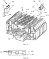
- FIG. 1C shows, schematically, an example terminal block 120 including multiple recess sensor apparatuses 130 and 140.
- the terminal block 120 may comprise multiple recesses as at 121A, 121B, and 121C.
- the sensor apparatuses 130 and 140 may comprise conducting probes 131 and 141, respectively, each configured in shape and size to pass through one or more of the recesses 121A, 121B, and 121C.
- a conducting probe 131 contacts an internal conductor 122 of the terminal block 120, thereby conducting a physical property of the internal conductor 122 to the sensor 132.
- the sensor apparatus 130 may comprise an electrical conductor 133 and a connector 134, that together transfer the electrical signal from the sensor to a controller (not shown), such as a controller on a circuit board.
- the sensor apparatus 140 may comprise a controller 142, such as an embedded controller.
- the controller 142 may be incorporated in a power device, a control system, and/or a Supervisory Control and Data Acquisition (SCADA) system.
- SCADA Supervisory Control and Data Acquisition
- the controller 142 may be configured to:
- the size of the conducting probe may be determined by the size of the terminal block recess (such as recesses 121A, 121B, and 121C), which in turn may be determined by the ampacity of the terminal block.
- a terminal block for conducting 195 A may be configured for a 12 mm diameter conductor or a 100 mm 2 ) cross sectional conductor area.
- a recess for this example may be of the same size or slightly larger to allow for insulation.
- a jumper recess may have a 5 mm by 20 mm rectangular shape, and/or a 10 mm by 10 mm square shape.
- the conducting probe tip may comprise a cross section of between 1 and 300 mm 2 , depending on the terminal block ampacity.
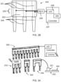
- FIG. 2A shows, schematically, a top view of an example three position terminal block jumper pass-through sensor apparatus 200.
- the sensor apparatus 200 may comprise recesses 201 and a connecting bridge 202, such as made from an insulating material.
- the probes may be configured with a cross-section shaped to enter a recess of a terminal block and connect to the internal conductor of the terminal block, such as comprising a cross-section shaped as a rounded rectangle, a squircle (i.e., a shape intermediate between a square and a circle), or a combination of square and round shapes.
- a rounded polygon shape may be configured to contact the electrical conductor recess walls by pressing the rounded corners (such as for a round shaped recess) and/or sides (such as for a rectangular shaped recess) of the polygon against the internal conductor. This may have the benefit of a single probe configuration connecting to the internal conductors of multiple makes and models of terminal block recesses.
- FIG. 2B shows, schematically, a side view of an example three position terminal block jumper pass-through sensor apparatus 200.
- the sensor apparatus 200 may comprise multiple probes 204 connected to a connecting bridge 202 of the sensor apparatus 200 and may be arranged in a linear array, such as a comb structure. Each probe element of the linear array fits into a recess or a terminal block arranged to match the comb/array structure (such as arranged in spacing, size and shape or probe elements).
- Recesses 201 may be located opposing the probe structures to allow connection of a jumper or bridge when needed.
- the sensor apparatus 200 may comprise multiple sensors 205, such as one for each probe 204, connected to a controller 207, such as serially through a multiplexor 206 (MUX).
- MUX multiplexor 206
- the MUX 206 may send multiple digital or analog values over one or more conductors by sharing the conductors for each sensor transfer. Once a first sensor transfer is complete, the MUX 206 may start sending the second sensor value. In this manner, multiple sensor values may be transferred serially.
- the controller 207 may comprise A/D converters 208 to convert the sensor measurements to digital values.
- the controller 207 may be configured to monitor the sensor 205 values, and when one or more values is abnormal, an action or message is initiated by the controller 207 using a data and/or communication interface 209.
- adjacent terminal blocks may be of different current ratings and/or sizes, and the conducting probes of the sensor apparatus may be arranged non-linearly, such a zigzag pattern, a traverse or diagonal pattern, or a matching pattern.
- each probe of the sensor apparatus has a different location corresponding to the location of a recess in the terminal block that probe is configured to enter.
- Abnormal sensor values may be determined based on rules, such as different from the other sensor values, different from previous sensor values, different from historically recorded sensor values, and/or above a threshold relative to the current passing through the terminal block associated with specific probe and sensor. For example, a sensor value of a temperature reading corresponding to a temperature of 95 °C may trigger a device shutdown. For example, six sensors monitor six terminal blocks, and five of the sensors report a value corresponding to a temperature of 67 °C and one sensor is 87 °C and as a result a warning is sent to a user interface indicated an abnormal temperature at the terminal block of the 6 th sensor.
- FIG. 3A shows, schematically, examples of sensor apparatuses 300, 310, 320, and 330.
- Probes shown as the "teeth" of the linear array, may be arranged in different configurations, such as a 10-probe sensor apparatus 300 with electrical conductors leading to a controller, a three-probe apparatus 310 with an integrated controller, a two-probe sensor apparatus 320 configured for adjacent terminal blocks, a two-probe sensor apparatus 330 configured for non-adjacent terminal blocks (with a connector 331 to a printed circuit board 332 comprising a controller 333).
- the controller may be on the probe, near the probe and connected with conductors to the sensors, integrated into a power device, and/or located on a remote server. Any of the example configurations of sensor probes may be matched to any of the examples of the controllers, as long as the controllers are configured to support the specific number of sensors on the probes.
- FIG. 3B shows, schematically, further examples of sensor apparatuses, such as number of probes, positions of probes, etc.:
- the sensor probes may be inserted into recesses of terminal lugs, such as terminal lugs connected to the terminal blocks.
- a high terminal block rated for 250 A may use electrical cable connections of terminal lugs, such as mechanical lugs.
- the terminal lug may include a hole or recess, into which a conducting probe may be inserted with associated sensor, controller, etc.
- FIG. 4 shows, schematically, examples of terminal lugs 400 and 410 with monitoring sensor recesses.
- the terminal lug 400 comprises a flange 401A and a terminal connection recess 401B. A bolt or screw is inserted through terminal connection recess 401B and tightened to electrically connect flange 401A to a terminal block.
- Terminal lug 400 An electrical cable or wire is connected to the terminal lug 400 by inserting the bare conductor (such as after removal of insulation) into a cable recess 403 and crimping the terminal lug body 402 around the conductor.
- a sensor recess 404 is positioned along flange 401A and the sensor apparatus probe inserted through recess 404 to allow the sensor attached to the probe to receive a physical property of the terminal, such as voltage and/or temperature.
- Terminal lug 410 is similar to terminal lug 400, but sensor recess 411B is located within a dedicated body element 411A protruding from the body of terminal lug 410.
- a sensor recess on the terminal lug may be used for measuring the voltage or temperature before the conductor reaches the terminal block (thus enabling the calculation of a temperature or voltage drop across the terminal block).
- the terminal block does not require a recess (such as a bridge or jumper recess). Since the probe and sensor may be incorporated into the terminal lug, fewer connections may be needed to connect during installation and hence the reliability may be improved over sensor apparatuses incorporated into the terminal blocks. Illustrated in FIG. 4 is a ring lug or eyelet lug, but similar aspects, with appropriate modification, may incorporate a fork lug, a pin lug, and/or a flange lug.
- FIG. 5A shows, schematically, an example of a terminal sensor clamp apparatus 500.
- Some figures herein contain multiple similar parts, and where relevant, the references have been made to one of the parts. It may be understood that due to the analogous nature of the multiple parts, the description of one of the parts may apply to the other corresponding parts.
- Apparatus 500 comprises a body 501 and a clamp 503 that may clamp around a terminal lug (similar or identical to terminal lug 400 or 410 of Fig. 4 ) as at 510, thereby connecting sensors (as at 508 and 509) to the series of terminal lugs (as at 510).
- Body 501 and clamp 503 may comprise conducting probes for transferring a physical property from the terminal lugs 510 to sensors 508 and 509, such as comprising a conducting material (electrically conducting and/or thermally conducting).
- the clamp 503 may have clamping teeth 507, one for each terminal lug 510.
- the clamp 503 may be pressed against the lugs using a spring or elastic device 511.
- the clamp 503 may be separated from terminal lugs 510 by using a level 502 operating around pivot 505, that when opened away from body 501 uses link arm 504 operating through pivots 506 to pull the clamping teeth 507 away from terminal lugs 510.
- FIG. 5B shows, schematically, another example of a terminal sensor clamp apparatus 520.
- the apparatus 520 comprises two sliding parts 521 and 522, where part 521 comprises a handle 524 and clamping appendages 525, and part 522 comprises a handle 523 and clamping appendages 526.
- Clamping appendages 525 and 526 may be conducting probes for transferring a physical property from terminal lugs 530 to sensors 528, such as comprising a conducting material (electrically conducting and/or thermally conducting).
- An elastic member 527 pulls clamping appendages 525 and 526 towards each other thereby applying pressure to terminal lugs 530 between them and pressing sensors 528 against terminal lugs 530.
- Operating handles 523 and 524 by grasping and pulling the handles towards each other, may allow inserting terminal lugs 530 between clamping appendages 525 and 526.
- apparatus 600 comprises clamps as at 605 and 606 which press sensors as at 607 and 608 against terminal lugs 620.
- Clamps 605 and 606 may be conducting probes for transferring a physical property from terminal lugs 620 to sensors 607 and 608, such as comprising a conducting material (electrically conducting and/or thermally conducting).
- Elastic members 612 such as a spring, forces clamps 605 and 606 (and sensors 607 and 608) against terminal lugs 620.
- Handle 604 may be attached to part 601, handle 603 may be attached to part 602, part 602 may be attached as at 613 to one opening cable as at 611 per clamp pair, and cable 611 may penetrate first clamp 606 and may be anchored as at 610 on second clamp 605.
- handles 603 and 604 may be pressed together, which may pull cables 611 such that the distal end of clamps 605 and 606 are pulled together, thereby opening the clamp for encompassing terminal lugs 620.
- Each clamp pair may be connected to part 601 with a flexible neck 609, so that small variations in positions of terminal lugs 620 have minor effect on the clamping strength and mechanism.
- Flexible neck 609 may comprise a lateral flexibility (side-to-side motion), and a longitudinal stiffness (along the length), enabling motion to the sides but allowing the opening clamp mechanism to operate.
- FIG. 7A, 7B , and 7C depict example devices and systems that may incorporate aspects of a sensor apparatus coupled to an electrical terminal, and as such, the terminal is depicted in these examples already incorporated into the AC or DC terminal, as the case may be.
- FIG. 7A shows, schematically, a combiner box 700 with terminal sensor probes.
- Combiner box 700 may comprise terminals with sensors probes 702A, 702B, 702C, 702D, 702E, and 702F, such as AC terminals (alternatively, the AC terminals may be configured for DC electrical power combining), each comprising a probe and sensor (not shown), such as the probes 101, 111, 131, 141, and 204, and sensors 104, 114, 132, 205, 508, 509, 528, 607, and 608 described in previous figures.
- sensors probes 702A, 702B, 702C, 702D, 702E, and 702F such as AC terminals (alternatively, the AC terminals may be configured for DC electrical power combining), each comprising a probe and sensor (not shown), such as the probes 101, 111, 131, 141, and 204, and sensors 104, 114, 132, 205, 508, 509, 528, 607, and 608 described in previous figures.
- Power sources 703A, 703B, 703C, 703D, and 703E each connect to one of input terminals 702A, 702B, 702C, 702D, and 702E, and for example output terminal 702F may be connected to an electrical grid 701 and/or other power device (not shown).
- Combiner box 700 may comprise a controller (not shown - such as or similar to controllers 107, 117, 142, 207, or 333) that monitors the sensors (such as or similar to sensors 104, 114, 132, 141, 205, 508, 509, 528, 607, or 608), and when a sensor value exceeds a threshold, such as an over-temperature threshold, an over-resistance threshold, an over/under-voltage threshold, a overpower dissipation threshold, and/or an abnormal terminal sensor value threshold (by comparing to other sensor values), the controller may send a message to a host system or user interface indicating the exceeded threshold and the terminal identifier (for assistance in initiating a repair of the faulty terminal).
- a controller not shown - such as or similar to controllers 107, 117, 142, 207, or 333
- the sensors such as or similar to sensors 104, 114, 132, 141, 205, 508, 509, 528, 607
- Power device 710 may comprise terminals with sensor probes 712A, 712B, 712C, and 712D, which may be AC or DC terminals, each comprising a probe and a sensor (not shown - such as or similar to controllers 107, 117, 142, 207, or 333).
- Power sources/sinks 713, 714, and 715 may be connected to input terminals with sensor probes 712B, 712C, 712A, respectively.
- device 715 may be a wind power generator connected to AC terminal 712A.
- device 713 may be a solar power generator connected to DC terminal 712B.
- device 714 may be an energy storage device, such as a residential home lithium ion battery, connected to DC terminal 712C.
- Power device 710 may comprise an output terminal 712D connected to an electrical grid 711.
- Power device 710 may comprise a controller (not shown) that monitors the sensors, and when a sensor value exceeds a threshold, such as an over-temperature threshold, an over-resistance threshold, an over/under-voltage threshold, a overpower dissipation threshold, and/or an abnormal terminal threshold (by comparing to the other sensor values), the controller may send a message to a host system or user interface indicating the exceeded threshold and the terminal identifier (for assistance in initiating a repair of the faulty terminal).
- a threshold such as an over-temperature threshold, an over-resistance threshold, an over/under-voltage threshold, a overpower dissipation threshold, and/or an abnormal terminal threshold (by comparing to the other sensor values)
- the controller may send a message to a host system
Landscapes
- Physics & Mathematics (AREA)
- General Physics & Mathematics (AREA)
- Engineering & Computer Science (AREA)
- Power Engineering (AREA)
- Architecture (AREA)
- Civil Engineering (AREA)
- Structural Engineering (AREA)
- Connections Arranged To Contact A Plurality Of Conductors (AREA)
- Arrangements For Transmission Of Measured Signals (AREA)
Claims (15)
- Gerät, umfassend:eine leitfähige Sonde (101, 204), die dazu konfiguriert ist, mit einem elektrischen Leiter eines elektrischen Anschlusses einer Stromversorgungsvorrichtung zu koppeln;einen Sensor (104, 205) in Kontakt mit der leitfähigen Sonde; undeine Steuerschaltung (107, 207), die elektrisch mit dem Sensor gekoppelt ist, wobei die Steuerschaltung dazu konfiguriert ist, Werte des Sensors zu überwachen, und die Steuerschaltung dazu konfiguriert ist, wenn bestimmt wird, dass die Werte des Sensors anormal sind, das Senken des Stroms, der durch den elektrischen Leiter fließt, einzuleiten/zu befehlen;wobei die leitfähige Sonde (101, 204) eine Vertiefung (102) umfasst, die dazu konfiguriert ist, eine Überbrückungsbrücke aufzunehmen, wobei die Überbrückungsbrücke in die Vertiefung eingesetzt wird, die leitfähige Sonde (101, 104) elektrisch mit dem elektrischen Anschluss und der Überbrückungsbrücke gekoppelt wird, wodurch der elektrische Anschluss und die Überbrückungsbrücke elektrisch gekoppelt werden.
- Gerät nach Anspruch 1, wobei die leitfähige Sonde (101, 204) thermisch leitfähig ist, wobei der Sensor ein Temperatursensor ist und wobei der Kontakt ein thermischer Kontakt ist.
- Gerät nach Anspruch 1 oder 2, wobei die leitfähige Sonde (101, 204) elektrisch leitfähig ist, wobei der Sensor ein Spannungssensor ist und wobei der Kontakt ein elektrischer Kontakt ist.
- Gerät nach einem der Ansprüche 1 bis 3, wobei der elektrische Anschluss einen Kabelschuh (400, 410) umfasst.
- Gerät nach Anspruch 4, wobei die leitfähige Sonde (101, 104) einen Klemmenmechanismus umfasst, um die leitfähige Sonde an den Kabelschuh des elektrischen Anschlusses zu koppeln.
- Gerät nach einem der Ansprüche 1 bis 5, wobei der Sensor (104, 205) ein Temperatursensor ist und weiter einen Spannungssensor umfasst.
- Gerät nach einem der Ansprüche 1 bis 6, das weiter ein Kommunikationsmodul zur Kommunikation mit einem Client-Endgerät umfasst, wobei eine Aktion unter Verwendung des Kommunikationsmoduls zu dem Client-Endgerät initiiert wird.
- Gerät nach einem der Ansprüche 1 bis 7, das weiter einen elektrischen Isolator (103) umfasst, der die leitfähige Sonde und den Sensor umgibt.
- Gerät nach den Ansprüchen 1 bis 8, wobei die Sensorwerte basierend auf einer Regel als anormal bestimmt werden.
- Gerät nach den Ansprüchen 1 bis 8, wobei die Sensorwerte basierend auf einer Regel als anormal bestimmt werden, wobei gemäß der Regel ein anormaler Sensorwert ein Wert ist, der sich von den Werten der anderen Sensoren unterscheidet, wobei gemäß der Regel ein anormaler Sensorwert ein Wert ist, der sich von vorherigen Sensorwerten unterscheidet, wobei gemäß der Regel ein anormaler Sensorwert ein Wert ist, der sich von historisch aufgezeichneten Sensorwerten unterscheidet, oder wobei gemäß der Regel ein anormaler Sensorwert über einem Schwellenwert liegt.
- Gerät nach einem der Ansprüche 1 bis 10, wobei die leitfähige Sonde (101, 204) dazu konfiguriert ist, in eine Vertiefung in einen Kabelschuh einzutreten.
- Gerät nach einem der Ansprüche 1 bis 11, das mehrere leitfähige Sonden (204) umfasst, wobei die mehreren leitfähigen Sonden isolierte elektrische Verbindungen umfassen und die isolierten elektrischen Verbindungen Strom an die Steuerschaltung liefern.
- Gerät nach einem der Ansprüche 1 bis 12, wobei die Steuerschaltung (107, 207) eine analoge Steuerschaltung oder eine digitale Steuerschaltung ist.
- Stromversorgungsvorrichtung, umfassend:einen elektrischen Anschluss, der einen elektrischen Leiter umfasst;eine leitfähige Sonde (101, 204), die dazu konfiguriert ist, mit dem elektrischen Leiter des elektrischen Anschlusses zu koppeln;einen Sensor (104, 205) in Kontakt mit der leitfähigen Sonde; undeine Steuervorrichtung (107, 207), die elektrisch mit dem Sensor gekoppelt ist, wobei die Steuervorrichtung dazu konfiguriert ist, Werte des Sensors zu überwachen, und die Steuervorrichtung dazu konfiguriert ist, wenn bestimmt wird, dass die Werte des Sensors anormal sind, das Senken des Stroms, der durch den elektrischen Leiter fließt, einzuleiten/zu befehlen;wobei die leitfähige Sonde (101, 204) eine Vertiefung (102) umfasst, die dazu konfiguriert ist, eine Überbrückungsbrücke aufzunehmen, wobei die Überbrückungsbrücke in die Vertiefung eingesetzt wird, die leitfähige Sonde (101, 104) elektrisch mit dem elektrischen Anschluss und der Überbrückungsbrücke gekoppelt wird, wodurch der elektrische Anschluss und die Überbrückungsbrücke elektrisch gekoppelt werden.
- Verfahren, das die Verwendung eines Hardware-Prozessors umfasst, um:Werte eines Sensors (104, 205) zu überwachen, wobei der Sensor mit einer leitfähigen Sonde (101, 204) in Kontakt ist, die eine Vertiefung (102) umfasst, die dazu konfiguriert ist, eine Überbrückungsbrücke aufzunehmen, wobei die leitfähige Sonde mit einem elektrischen Leiter (122) eines elektrischen Anschlusses (120) einer Stromversorgungsvorrichtung gekoppelt ist, wobei die leitfähige Sonde dazu konfiguriert ist, in eine Vertiefung (121A-C) des elektrischen Anschlusses eingesetzt zu werden, wobei die Überbrückungsbrücke in die Vertiefung eingesetzt wird, die leitfähige Sonde (101, 104) elektrisch mit dem elektrischen Anschluss und der Überbrückungsbrücke gekoppelt wird, wodurch der elektrische Anschluss und die Überbrückungsbrücke elektrisch gekoppelt werden; undwenn die Werte des Sensors anormal sind, das Senken des Stroms, der durch den elektrischen Leiter fließt, einzuleiten/zu befehlen.
Applications Claiming Priority (1)
| Application Number | Priority Date | Filing Date | Title |
|---|---|---|---|
| US201962893253P | 2019-08-29 | 2019-08-29 |
Publications (2)
| Publication Number | Publication Date |
|---|---|
| EP3786648A1 EP3786648A1 (de) | 2021-03-03 |
| EP3786648B1 true EP3786648B1 (de) | 2025-06-25 |
Family
ID=72292263
Family Applications (1)
| Application Number | Title | Priority Date | Filing Date |
|---|---|---|---|
| EP20193381.9A Active EP3786648B1 (de) | 2019-08-29 | 2020-08-28 | Anschlusssensoranordnung |
Country Status (3)
| Country | Link |
|---|---|
| US (2) | US11879911B2 (de) |
| EP (1) | EP3786648B1 (de) |
| CN (1) | CN112525375A (de) |
Families Citing this family (1)
| Publication number | Priority date | Publication date | Assignee | Title |
|---|---|---|---|---|
| US12316090B2 (en) * | 2023-03-08 | 2025-05-27 | Pratt & Whitney Canada Corp. | Temperature sensor for arc detection |
Family Cites Families (21)
| Publication number | Priority date | Publication date | Assignee | Title |
|---|---|---|---|---|
| US5073402A (en) * | 1989-03-16 | 1991-12-17 | Medical Laser Technologies Limited Of Research Park | Method of making an optical device |
| US5644245A (en) * | 1993-11-24 | 1997-07-01 | Tokyo Electron Limited | Probe apparatus for inspecting electrical characteristics of a microelectronic element |
| CA2803757C (en) * | 2004-09-03 | 2015-10-20 | Watlow Electric Manufacturing Company | Power control system |
| DE112006002329B4 (de) * | 2005-08-29 | 2022-06-09 | Midtronics, Inc. | Diagnosevorrichtung für elektrische Anlagen von Kraftfahrzeugen |
| ITMI20080513A1 (it) | 2008-03-27 | 2009-09-28 | Cabur S R L | Dispositivo connettore perfezionato per il collegamento elettrico tra morsetti elettrici, metodo per la realizzazione di tale dispositivo connettore e gruppo di collegamento elettrico dotato di tale dispositivo connettore perfezionato |
| US7902848B2 (en) * | 2009-01-09 | 2011-03-08 | Fluke Corporation | Reversible test probe and test probe tip |
| US9577443B2 (en) * | 2010-06-03 | 2017-02-21 | C&C Power, Inc. | Battery system and management method |
| KR101016770B1 (ko) * | 2010-06-18 | 2011-02-25 | (주)케이디티 | 병렬방식의 데이터 버스를 이용한 모듈형 계측기 통합 시스템 |
| US9354158B1 (en) * | 2012-01-20 | 2016-05-31 | Tasseron Sensors, Inc. | Duct averaging sensor having a connector |
| US20140070831A1 (en) * | 2012-08-27 | 2014-03-13 | Advantest Corporation | System and method of protecting probes by using an intelligent current sensing switch |
| US10761147B2 (en) * | 2016-11-21 | 2020-09-01 | GRID20/20, Inc. | Transformer monitoring and data analysis systems and methods |
| KR102027743B1 (ko) * | 2013-08-28 | 2019-11-04 | 한국전력공사 | 전력 케이블 접속부의 통전 및 온도 통합 감시 시스템 |
| EP3105827A4 (de) | 2014-02-13 | 2017-11-15 | Erico International Corporation | Lösbarer spleissblock und modulare überspannungsschutzvorrichtung |
| FR3023429A1 (fr) * | 2014-07-02 | 2016-01-08 | Schneider Electric Ind Sas | Equipement modulaire de tele-conduite |
| TWI592071B (zh) * | 2014-11-14 | 2017-07-11 | Mpi Corp | Multilayer circuit board |
| ES2688038T3 (es) * | 2014-12-12 | 2018-10-30 | Yazaki Europe Ltd | Conjunto de conector eléctrico y disposición de conexión |
| JP6622491B2 (ja) * | 2015-06-22 | 2019-12-18 | Koa株式会社 | 電流検出装置及びその製造方法 |
| GB2552447B (en) * | 2016-04-06 | 2019-06-12 | Qhi Group Ltd | Fault monitoring systems and methods for detecting connectivity faults |
| JP6467383B2 (ja) * | 2016-08-10 | 2019-02-13 | 矢崎総業株式会社 | コネクタ |
| US10267833B2 (en) * | 2016-11-02 | 2019-04-23 | Equinix, Inc. | Power monitoring probe for monitoring power distribution in an electrical system |
| CN107290620A (zh) * | 2017-07-07 | 2017-10-24 | 吉林大洋电气科技有限公司 | 一种智能型插接箱 |
-
2020
- 2020-08-28 EP EP20193381.9A patent/EP3786648B1/de active Active
- 2020-08-28 CN CN202010883999.4A patent/CN112525375A/zh active Pending
- 2020-08-28 US US17/005,494 patent/US11879911B2/en active Active
-
2023
- 2023-12-18 US US18/543,117 patent/US12399196B2/en active Active
Also Published As
| Publication number | Publication date |
|---|---|
| US11879911B2 (en) | 2024-01-23 |
| EP3786648A1 (de) | 2021-03-03 |
| US20240118311A1 (en) | 2024-04-11 |
| CN112525375A (zh) | 2021-03-19 |
| US12399196B2 (en) | 2025-08-26 |
| US20210063437A1 (en) | 2021-03-04 |
Similar Documents
| Publication | Publication Date | Title |
|---|---|---|
| AU2022215279B2 (en) | Terminal and disconnection link | |
| RU2532417C2 (ru) | Контроль температуры для шинной распределительной системы | |
| TWI588354B (zh) | 監控一線股內之多電能線的方法 | |
| US12009160B2 (en) | Monitoring method for an electric power transmission device | |
| US12399196B2 (en) | Terminal sensor array | |
| CN104487277A (zh) | 用于保护充电线的方法以及充电装置 | |
| US20170295672A1 (en) | Circuit breaker arrangements | |
| CN107947127A (zh) | 一种配电柜温度保护系统 | |
| EP2779200B1 (de) | Messmodul für einen Sicherungsblocksockel | |
| CN208903946U (zh) | 一种用于导电系统的温度传感器的绝缘连接结构 | |
| CN212693098U (zh) | 高压开关设备回路连接结构测温系统 | |
| EP4283267B1 (de) | Überwachung der integrität von cross-bonding-boxen | |
| Kusmayadi et al. | PROSEDUR PENGECEKAN DAN PENANGANAN HOTSPOT PADA PMS GARDU INDUK 150 KV PEMATANGSIANTAR MENGGUNAKAN METODE THERMOVISION | |
| EP4345433B1 (de) | Schaltgerät | |
| CN219779372U (zh) | 一种柔性电连接件及母线槽连接结构 | |
| CN221226773U (zh) | 一种组合式短接条 | |
| GERHANA DANANJAYA | TEMPERATURE ANALYSIS OF 2x1. 5mm² NYM CABLE BENDING ON CURRENT LARGE | |
| CN211508464U (zh) | 一种新型配电柜用电缆线固定夹 | |
| EP2409305B1 (de) | Widerstandsbauelement, verfahren zu seiner herstellung und lastverteilungssystem | |
| CN121769785A (zh) | 功率变换设备、功率变换设备的保护方法及端子 | |
| EP3078091B1 (de) | Abgangskasten mit überbrückungsmodul | |
| CN107887795A (zh) | 一种智能母排系统 | |
| CN118040487A (zh) | 一种环网柜、箱式变电站及供电系统 | |
| CN117955059A (zh) | 一种供电系统 | |
| KR20230137712A (ko) | 초고압 차단기의 온도 측정 장치 |
Legal Events
| Date | Code | Title | Description |
|---|---|---|---|
| PUAI | Public reference made under article 153(3) epc to a published international application that has entered the european phase |
Free format text: ORIGINAL CODE: 0009012 |
|
| STAA | Information on the status of an ep patent application or granted ep patent |
Free format text: STATUS: THE APPLICATION HAS BEEN PUBLISHED |
|
| AK | Designated contracting states |
Kind code of ref document: A1 Designated state(s): AL AT BE BG CH CY CZ DE DK EE ES FI FR GB GR HR HU IE IS IT LI LT LU LV MC MK MT NL NO PL PT RO RS SE SI SK SM TR |
|
| AX | Request for extension of the european patent |
Extension state: BA ME |
|
| STAA | Information on the status of an ep patent application or granted ep patent |
Free format text: STATUS: REQUEST FOR EXAMINATION WAS MADE |
|
| 17P | Request for examination filed |
Effective date: 20210902 |
|
| RBV | Designated contracting states (corrected) |
Designated state(s): AL AT BE BG CH CY CZ DE DK EE ES FI FR GB GR HR HU IE IS IT LI LT LU LV MC MK MT NL NO PL PT RO RS SE SI SK SM TR |
|
| P01 | Opt-out of the competence of the unified patent court (upc) registered |
Effective date: 20230505 |
|
| STAA | Information on the status of an ep patent application or granted ep patent |
Free format text: STATUS: EXAMINATION IS IN PROGRESS |
|
| 17Q | First examination report despatched |
Effective date: 20231213 |
|
| GRAP | Despatch of communication of intention to grant a patent |
Free format text: ORIGINAL CODE: EPIDOSNIGR1 |
|
| STAA | Information on the status of an ep patent application or granted ep patent |
Free format text: STATUS: GRANT OF PATENT IS INTENDED |
|
| INTG | Intention to grant announced |
Effective date: 20250122 |
|
| GRAS | Grant fee paid |
Free format text: ORIGINAL CODE: EPIDOSNIGR3 |
|
| GRAA | (expected) grant |
Free format text: ORIGINAL CODE: 0009210 |
|
| STAA | Information on the status of an ep patent application or granted ep patent |
Free format text: STATUS: THE PATENT HAS BEEN GRANTED |
|
| AK | Designated contracting states |
Kind code of ref document: B1 Designated state(s): AL AT BE BG CH CY CZ DE DK EE ES FI FR GB GR HR HU IE IS IT LI LT LU LV MC MK MT NL NO PL PT RO RS SE SI SK SM TR |
|
| REG | Reference to a national code |
Ref country code: GB Ref legal event code: FG4D |
|
| REG | Reference to a national code |
Ref country code: CH Ref legal event code: EP |
|
| REG | Reference to a national code |
Ref country code: DE Ref legal event code: R096 Ref document number: 602020053201 Country of ref document: DE |
|
| REG | Reference to a national code |
Ref country code: CH Ref legal event code: EP |
|
| REG | Reference to a national code |
Ref country code: IE Ref legal event code: FG4D |
|
| REG | Reference to a national code |
Ref country code: NL Ref legal event code: FP |
|
| PGFP | Annual fee paid to national office [announced via postgrant information from national office to epo] |
Ref country code: NL Payment date: 20250826 Year of fee payment: 6 |
|
| PG25 | Lapsed in a contracting state [announced via postgrant information from national office to epo] |
Ref country code: FI Free format text: LAPSE BECAUSE OF FAILURE TO SUBMIT A TRANSLATION OF THE DESCRIPTION OR TO PAY THE FEE WITHIN THE PRESCRIBED TIME-LIMIT Effective date: 20250625 |
|
| PGFP | Annual fee paid to national office [announced via postgrant information from national office to epo] |
Ref country code: DE Payment date: 20250827 Year of fee payment: 6 |
|
| REG | Reference to a national code |
Ref country code: LT Ref legal event code: MG9D |
|
| PG25 | Lapsed in a contracting state [announced via postgrant information from national office to epo] |
Ref country code: GR Free format text: LAPSE BECAUSE OF FAILURE TO SUBMIT A TRANSLATION OF THE DESCRIPTION OR TO PAY THE FEE WITHIN THE PRESCRIBED TIME-LIMIT Effective date: 20250926 Ref country code: NO Free format text: LAPSE BECAUSE OF FAILURE TO SUBMIT A TRANSLATION OF THE DESCRIPTION OR TO PAY THE FEE WITHIN THE PRESCRIBED TIME-LIMIT Effective date: 20250925 |
|
| PG25 | Lapsed in a contracting state [announced via postgrant information from national office to epo] |
Ref country code: BG Free format text: LAPSE BECAUSE OF FAILURE TO SUBMIT A TRANSLATION OF THE DESCRIPTION OR TO PAY THE FEE WITHIN THE PRESCRIBED TIME-LIMIT Effective date: 20250625 |
|
| PGFP | Annual fee paid to national office [announced via postgrant information from national office to epo] |
Ref country code: GB Payment date: 20250827 Year of fee payment: 6 |
|
| PG25 | Lapsed in a contracting state [announced via postgrant information from national office to epo] |
Ref country code: HR Free format text: LAPSE BECAUSE OF FAILURE TO SUBMIT A TRANSLATION OF THE DESCRIPTION OR TO PAY THE FEE WITHIN THE PRESCRIBED TIME-LIMIT Effective date: 20250625 |
|
| PGFP | Annual fee paid to national office [announced via postgrant information from national office to epo] |
Ref country code: FR Payment date: 20250825 Year of fee payment: 6 |
|
| PG25 | Lapsed in a contracting state [announced via postgrant information from national office to epo] |
Ref country code: RS Free format text: LAPSE BECAUSE OF FAILURE TO SUBMIT A TRANSLATION OF THE DESCRIPTION OR TO PAY THE FEE WITHIN THE PRESCRIBED TIME-LIMIT Effective date: 20250925 |
|
| PG25 | Lapsed in a contracting state [announced via postgrant information from national office to epo] |
Ref country code: LV Free format text: LAPSE BECAUSE OF FAILURE TO SUBMIT A TRANSLATION OF THE DESCRIPTION OR TO PAY THE FEE WITHIN THE PRESCRIBED TIME-LIMIT Effective date: 20250625 |
|
| PG25 | Lapsed in a contracting state [announced via postgrant information from national office to epo] |
Ref country code: PT Free format text: LAPSE BECAUSE OF FAILURE TO SUBMIT A TRANSLATION OF THE DESCRIPTION OR TO PAY THE FEE WITHIN THE PRESCRIBED TIME-LIMIT Effective date: 20251027 |
|
| REG | Reference to a national code |
Ref country code: AT Ref legal event code: MK05 Ref document number: 1806966 Country of ref document: AT Kind code of ref document: T Effective date: 20250625 |
|
| PG25 | Lapsed in a contracting state [announced via postgrant information from national office to epo] |
Ref country code: IS Free format text: LAPSE BECAUSE OF FAILURE TO SUBMIT A TRANSLATION OF THE DESCRIPTION OR TO PAY THE FEE WITHIN THE PRESCRIBED TIME-LIMIT Effective date: 20251025 |
|
| PG25 | Lapsed in a contracting state [announced via postgrant information from national office to epo] |
Ref country code: AT Free format text: LAPSE BECAUSE OF FAILURE TO SUBMIT A TRANSLATION OF THE DESCRIPTION OR TO PAY THE FEE WITHIN THE PRESCRIBED TIME-LIMIT Effective date: 20250625 Ref country code: SM Free format text: LAPSE BECAUSE OF FAILURE TO SUBMIT A TRANSLATION OF THE DESCRIPTION OR TO PAY THE FEE WITHIN THE PRESCRIBED TIME-LIMIT Effective date: 20250625 |
|
| PG25 | Lapsed in a contracting state [announced via postgrant information from national office to epo] |
Ref country code: CZ Free format text: LAPSE BECAUSE OF FAILURE TO SUBMIT A TRANSLATION OF THE DESCRIPTION OR TO PAY THE FEE WITHIN THE PRESCRIBED TIME-LIMIT Effective date: 20250625 |
|
| PG25 | Lapsed in a contracting state [announced via postgrant information from national office to epo] |
Ref country code: PL Free format text: LAPSE BECAUSE OF FAILURE TO SUBMIT A TRANSLATION OF THE DESCRIPTION OR TO PAY THE FEE WITHIN THE PRESCRIBED TIME-LIMIT Effective date: 20250625 |
|
| PG25 | Lapsed in a contracting state [announced via postgrant information from national office to epo] |
Ref country code: EE Free format text: LAPSE BECAUSE OF FAILURE TO SUBMIT A TRANSLATION OF THE DESCRIPTION OR TO PAY THE FEE WITHIN THE PRESCRIBED TIME-LIMIT Effective date: 20250625 |
|
| PG25 | Lapsed in a contracting state [announced via postgrant information from national office to epo] |
Ref country code: SK Free format text: LAPSE BECAUSE OF FAILURE TO SUBMIT A TRANSLATION OF THE DESCRIPTION OR TO PAY THE FEE WITHIN THE PRESCRIBED TIME-LIMIT Effective date: 20250625 |
|
| PG25 | Lapsed in a contracting state [announced via postgrant information from national office to epo] |
Ref country code: ES Free format text: LAPSE BECAUSE OF FAILURE TO SUBMIT A TRANSLATION OF THE DESCRIPTION OR TO PAY THE FEE WITHIN THE PRESCRIBED TIME-LIMIT Effective date: 20250625 |
|
| PG25 | Lapsed in a contracting state [announced via postgrant information from national office to epo] |
Ref country code: RO Free format text: LAPSE BECAUSE OF FAILURE TO SUBMIT A TRANSLATION OF THE DESCRIPTION OR TO PAY THE FEE WITHIN THE PRESCRIBED TIME-LIMIT Effective date: 20250625 |
|
| REG | Reference to a national code |
Ref country code: CH Ref legal event code: H13 Free format text: ST27 STATUS EVENT CODE: U-0-0-H10-H13 (AS PROVIDED BY THE NATIONAL OFFICE) Effective date: 20260324 |
|
| PG25 | Lapsed in a contracting state [announced via postgrant information from national office to epo] |
Ref country code: MC Free format text: LAPSE BECAUSE OF FAILURE TO SUBMIT A TRANSLATION OF THE DESCRIPTION OR TO PAY THE FEE WITHIN THE PRESCRIBED TIME-LIMIT Effective date: 20250625 |
|
| PG25 | Lapsed in a contracting state [announced via postgrant information from national office to epo] |
Ref country code: DK Free format text: LAPSE BECAUSE OF FAILURE TO SUBMIT A TRANSLATION OF THE DESCRIPTION OR TO PAY THE FEE WITHIN THE PRESCRIBED TIME-LIMIT Effective date: 20250625 |
|
| PG25 | Lapsed in a contracting state [announced via postgrant information from national office to epo] |
Ref country code: LU Free format text: LAPSE BECAUSE OF NON-PAYMENT OF DUE FEES Effective date: 20250828 Ref country code: IT Free format text: LAPSE BECAUSE OF FAILURE TO SUBMIT A TRANSLATION OF THE DESCRIPTION OR TO PAY THE FEE WITHIN THE PRESCRIBED TIME-LIMIT Effective date: 20250625 |
|
| PG25 | Lapsed in a contracting state [announced via postgrant information from national office to epo] |
Ref country code: CH Free format text: LAPSE BECAUSE OF NON-PAYMENT OF DUE FEES Effective date: 20250831 |
|
| PLBE | No opposition filed within time limit |
Free format text: ORIGINAL CODE: 0009261 |
|
| STAA | Information on the status of an ep patent application or granted ep patent |
Free format text: STATUS: NO OPPOSITION FILED WITHIN TIME LIMIT |
|
| REG | Reference to a national code |
Ref country code: CH Ref legal event code: L10 Free format text: ST27 STATUS EVENT CODE: U-0-0-L10-L00 (AS PROVIDED BY THE NATIONAL OFFICE) Effective date: 20260507 |