EP3786646A1 - Battery electrode analysis method - Google Patents
Battery electrode analysis method Download PDFInfo
- Publication number
- EP3786646A1 EP3786646A1 EP19874260.3A EP19874260A EP3786646A1 EP 3786646 A1 EP3786646 A1 EP 3786646A1 EP 19874260 A EP19874260 A EP 19874260A EP 3786646 A1 EP3786646 A1 EP 3786646A1
- Authority
- EP
- European Patent Office
- Prior art keywords
- electrode
- pores
- epoxy group
- secondary battery
- active material
- Prior art date
- Legal status (The legal status is an assumption and is not a legal conclusion. Google has not performed a legal analysis and makes no representation as to the accuracy of the status listed.)
- Granted
Links
- 238000004458 analytical method Methods 0.000 title description 2
- 238000000034 method Methods 0.000 claims abstract description 26
- 238000004570 scanning spreading resistance microscopy Methods 0.000 claims abstract description 18
- 229920000642 polymer Polymers 0.000 claims description 51
- 125000003700 epoxy group Chemical group 0.000 claims description 48
- 239000011148 porous material Substances 0.000 claims description 47
- 239000004020 conductor Substances 0.000 claims description 34
- 239000007772 electrode material Substances 0.000 claims description 32
- 238000010884 ion-beam technique Methods 0.000 claims description 17
- 238000000992 sputter etching Methods 0.000 claims description 13
- XKRFYHLGVUSROY-UHFFFAOYSA-N Argon Chemical compound [Ar] XKRFYHLGVUSROY-UHFFFAOYSA-N 0.000 claims description 12
- 229910052786 argon Inorganic materials 0.000 claims description 6
- 230000001678 irradiating effect Effects 0.000 claims description 4
- 239000000463 material Substances 0.000 abstract description 14
- 239000000470 constituent Substances 0.000 abstract description 12
- 239000000523 sample Substances 0.000 description 29
- 239000011230 binding agent Substances 0.000 description 10
- 238000009826 distribution Methods 0.000 description 10
- 238000003892 spreading Methods 0.000 description 7
- 230000000052 comparative effect Effects 0.000 description 6
- 239000007774 positive electrode material Substances 0.000 description 5
- 230000008901 benefit Effects 0.000 description 4
- 230000000694 effects Effects 0.000 description 4
- 125000003118 aryl group Chemical group 0.000 description 3
- 238000002360 preparation method Methods 0.000 description 3
- KAKZBPTYRLMSJV-UHFFFAOYSA-N Butadiene Chemical compound C=CC=C KAKZBPTYRLMSJV-UHFFFAOYSA-N 0.000 description 2
- 239000004593 Epoxy Substances 0.000 description 2
- IAYPIBMASNFSPL-UHFFFAOYSA-N Ethylene oxide Chemical compound C1CO1 IAYPIBMASNFSPL-UHFFFAOYSA-N 0.000 description 2
- 239000011149 active material Substances 0.000 description 2
- 239000003575 carbonaceous material Substances 0.000 description 2
- 238000007796 conventional method Methods 0.000 description 2
- 229910003460 diamond Inorganic materials 0.000 description 2
- 239000010432 diamond Substances 0.000 description 2
- 239000003822 epoxy resin Substances 0.000 description 2
- 239000007788 liquid Substances 0.000 description 2
- AHHWIHXENZJRFG-UHFFFAOYSA-N oxetane Chemical compound C1COC1 AHHWIHXENZJRFG-UHFFFAOYSA-N 0.000 description 2
- 229920000647 polyepoxide Polymers 0.000 description 2
- KUBDPQJOLOUJRM-UHFFFAOYSA-N 2-(chloromethyl)oxirane;4-[2-(4-hydroxyphenyl)propan-2-yl]phenol Chemical compound ClCC1CO1.C=1C=C(O)C=CC=1C(C)(C)C1=CC=C(O)C=C1 KUBDPQJOLOUJRM-UHFFFAOYSA-N 0.000 description 1
- QTWJRLJHJPIABL-UHFFFAOYSA-N 2-methylphenol;3-methylphenol;4-methylphenol Chemical compound CC1=CC=C(O)C=C1.CC1=CC=CC(O)=C1.CC1=CC=CC=C1O QTWJRLJHJPIABL-UHFFFAOYSA-N 0.000 description 1
- 229930185605 Bisphenol Natural products 0.000 description 1
- OKTJSMMVPCPJKN-UHFFFAOYSA-N Carbon Chemical compound [C] OKTJSMMVPCPJKN-UHFFFAOYSA-N 0.000 description 1
- 229920002134 Carboxymethyl cellulose Polymers 0.000 description 1
- WHXSMMKQMYFTQS-UHFFFAOYSA-N Lithium Chemical compound [Li] WHXSMMKQMYFTQS-UHFFFAOYSA-N 0.000 description 1
- ISWSIDIOOBJBQZ-UHFFFAOYSA-N Phenol Chemical compound OC1=CC=CC=C1 ISWSIDIOOBJBQZ-UHFFFAOYSA-N 0.000 description 1
- XUIMIQQOPSSXEZ-UHFFFAOYSA-N Silicon Chemical compound [Si] XUIMIQQOPSSXEZ-UHFFFAOYSA-N 0.000 description 1
- FDLZQPXZHIFURF-UHFFFAOYSA-N [O-2].[Ti+4].[Li+] Chemical compound [O-2].[Ti+4].[Li+] FDLZQPXZHIFURF-UHFFFAOYSA-N 0.000 description 1
- NIXOWILDQLNWCW-UHFFFAOYSA-N acrylic acid group Chemical group C(C=C)(=O)O NIXOWILDQLNWCW-UHFFFAOYSA-N 0.000 description 1
- 239000000654 additive Substances 0.000 description 1
- 125000001931 aliphatic group Chemical group 0.000 description 1
- 229910021383 artificial graphite Inorganic materials 0.000 description 1
- IISBACLAFKSPIT-UHFFFAOYSA-N bisphenol A Chemical compound C=1C=C(O)C=CC=1C(C)(C)C1=CC=C(O)C=C1 IISBACLAFKSPIT-UHFFFAOYSA-N 0.000 description 1
- 239000003795 chemical substances by application Substances 0.000 description 1
- 150000001875 compounds Chemical class 0.000 description 1
- 229930003836 cresol Natural products 0.000 description 1
- 125000004122 cyclic group Chemical group 0.000 description 1
- 230000003247 decreasing effect Effects 0.000 description 1
- 150000001993 dienes Chemical class 0.000 description 1
- 239000003792 electrolyte Substances 0.000 description 1
- 239000007789 gas Substances 0.000 description 1
- 229910021385 hard carbon Inorganic materials 0.000 description 1
- 150000002500 ions Chemical class 0.000 description 1
- 229910052744 lithium Inorganic materials 0.000 description 1
- 239000000203 mixture Substances 0.000 description 1
- 229910021382 natural graphite Inorganic materials 0.000 description 1
- 239000007773 negative electrode material Substances 0.000 description 1
- 229920003986 novolac Polymers 0.000 description 1
- 125000001997 phenyl group Chemical group [H]C1=C([H])C([H])=C(*)C([H])=C1[H] 0.000 description 1
- 239000002861 polymer material Substances 0.000 description 1
- 238000011002 quantification Methods 0.000 description 1
- 229910052710 silicon Inorganic materials 0.000 description 1
- 239000010703 silicon Substances 0.000 description 1
- 239000007787 solid Substances 0.000 description 1
- -1 xyloxy Chemical group 0.000 description 1
Images


Classifications
-
- G—PHYSICS
- G01—MEASURING; TESTING
- G01Q—SCANNING-PROBE TECHNIQUES OR APPARATUS; APPLICATIONS OF SCANNING-PROBE TECHNIQUES, e.g. SCANNING PROBE MICROSCOPY [SPM]
- G01Q30/00—Auxiliary means serving to assist or improve the scanning probe techniques or apparatus, e.g. display or data processing devices
- G01Q30/20—Sample handling devices or methods
-
- G—PHYSICS
- G01—MEASURING; TESTING
- G01Q—SCANNING-PROBE TECHNIQUES OR APPARATUS; APPLICATIONS OF SCANNING-PROBE TECHNIQUES, e.g. SCANNING PROBE MICROSCOPY [SPM]
- G01Q60/00—Particular types of SPM [Scanning Probe Microscopy] or microscopes; Essential components thereof
- G01Q60/24—AFM [Atomic Force Microscopy] or apparatus therefor, e.g. AFM probes
- G01Q60/30—Scanning potential microscopy
-
- G—PHYSICS
- G01—MEASURING; TESTING
- G01N—INVESTIGATING OR ANALYSING MATERIALS BY DETERMINING THEIR CHEMICAL OR PHYSICAL PROPERTIES
- G01N1/00—Sampling; Preparing specimens for investigation
- G01N1/28—Preparing specimens for investigation including physical details of (bio-)chemical methods covered elsewhere, e.g. G01N33/50, C12Q
- G01N1/286—Preparing specimens for investigation including physical details of (bio-)chemical methods covered elsewhere, e.g. G01N33/50, C12Q involving mechanical work, e.g. chopping, disintegrating, compacting, homogenising
-
- G—PHYSICS
- G01—MEASURING; TESTING
- G01N—INVESTIGATING OR ANALYSING MATERIALS BY DETERMINING THEIR CHEMICAL OR PHYSICAL PROPERTIES
- G01N1/00—Sampling; Preparing specimens for investigation
- G01N1/28—Preparing specimens for investigation including physical details of (bio-)chemical methods covered elsewhere, e.g. G01N33/50, C12Q
- G01N1/44—Sample treatment involving radiation, e.g. heat
-
- G—PHYSICS
- G01—MEASURING; TESTING
- G01Q—SCANNING-PROBE TECHNIQUES OR APPARATUS; APPLICATIONS OF SCANNING-PROBE TECHNIQUES, e.g. SCANNING PROBE MICROSCOPY [SPM]
- G01Q30/00—Auxiliary means serving to assist or improve the scanning probe techniques or apparatus, e.g. display or data processing devices
- G01Q30/04—Display or data processing devices
-
- G—PHYSICS
- G06—COMPUTING; CALCULATING OR COUNTING
- G06T—IMAGE DATA PROCESSING OR GENERATION, IN GENERAL
- G06T1/00—General purpose image data processing
- G06T1/0007—Image acquisition
-
- G—PHYSICS
- G06—COMPUTING; CALCULATING OR COUNTING
- G06T—IMAGE DATA PROCESSING OR GENERATION, IN GENERAL
- G06T5/00—Image enhancement or restoration
- G06T5/50—Image enhancement or restoration using two or more images, e.g. averaging or subtraction
-
- G—PHYSICS
- G06—COMPUTING; CALCULATING OR COUNTING
- G06T—IMAGE DATA PROCESSING OR GENERATION, IN GENERAL
- G06T7/00—Image analysis
- G06T7/0002—Inspection of images, e.g. flaw detection
- G06T7/0004—Industrial image inspection
-
- H—ELECTRICITY
- H01—ELECTRIC ELEMENTS
- H01M—PROCESSES OR MEANS, e.g. BATTERIES, FOR THE DIRECT CONVERSION OF CHEMICAL ENERGY INTO ELECTRICAL ENERGY
- H01M10/00—Secondary cells; Manufacture thereof
- H01M10/42—Methods or arrangements for servicing or maintenance of secondary cells or secondary half-cells
- H01M10/4285—Testing apparatus
-
- H—ELECTRICITY
- H01—ELECTRIC ELEMENTS
- H01M—PROCESSES OR MEANS, e.g. BATTERIES, FOR THE DIRECT CONVERSION OF CHEMICAL ENERGY INTO ELECTRICAL ENERGY
- H01M4/00—Electrodes
- H01M4/02—Electrodes composed of, or comprising, active material
- H01M4/13—Electrodes for accumulators with non-aqueous electrolyte, e.g. for lithium-accumulators; Processes of manufacture thereof
- H01M4/139—Processes of manufacture
-
- H—ELECTRICITY
- H01—ELECTRIC ELEMENTS
- H01M—PROCESSES OR MEANS, e.g. BATTERIES, FOR THE DIRECT CONVERSION OF CHEMICAL ENERGY INTO ELECTRICAL ENERGY
- H01M4/00—Electrodes
- H01M4/02—Electrodes composed of, or comprising, active material
- H01M4/62—Selection of inactive substances as ingredients for active masses, e.g. binders, fillers
-
- G—PHYSICS
- G06—COMPUTING; CALCULATING OR COUNTING
- G06T—IMAGE DATA PROCESSING OR GENERATION, IN GENERAL
- G06T2207/00—Indexing scheme for image analysis or image enhancement
- G06T2207/10—Image acquisition modality
- G06T2207/10056—Microscopic image
- G06T2207/10061—Microscopic image from scanning electron microscope
-
- G—PHYSICS
- G06—COMPUTING; CALCULATING OR COUNTING
- G06T—IMAGE DATA PROCESSING OR GENERATION, IN GENERAL
- G06T2207/00—Indexing scheme for image analysis or image enhancement
- G06T2207/20—Special algorithmic details
- G06T2207/20212—Image combination
- G06T2207/20221—Image fusion; Image merging
-
- G—PHYSICS
- G06—COMPUTING; CALCULATING OR COUNTING
- G06T—IMAGE DATA PROCESSING OR GENERATION, IN GENERAL
- G06T2207/00—Indexing scheme for image analysis or image enhancement
- G06T2207/30—Subject of image; Context of image processing
- G06T2207/30108—Industrial image inspection
-
- H—ELECTRICITY
- H01—ELECTRIC ELEMENTS
- H01M—PROCESSES OR MEANS, e.g. BATTERIES, FOR THE DIRECT CONVERSION OF CHEMICAL ENERGY INTO ELECTRICAL ENERGY
- H01M4/00—Electrodes
- H01M4/02—Electrodes composed of, or comprising, active material
- H01M4/13—Electrodes for accumulators with non-aqueous electrolyte, e.g. for lithium-accumulators; Processes of manufacture thereof
-
- Y—GENERAL TAGGING OF NEW TECHNOLOGICAL DEVELOPMENTS; GENERAL TAGGING OF CROSS-SECTIONAL TECHNOLOGIES SPANNING OVER SEVERAL SECTIONS OF THE IPC; TECHNICAL SUBJECTS COVERED BY FORMER USPC CROSS-REFERENCE ART COLLECTIONS [XRACs] AND DIGESTS
- Y02—TECHNOLOGIES OR APPLICATIONS FOR MITIGATION OR ADAPTATION AGAINST CLIMATE CHANGE
- Y02E—REDUCTION OF GREENHOUSE GAS [GHG] EMISSIONS, RELATED TO ENERGY GENERATION, TRANSMISSION OR DISTRIBUTION
- Y02E60/00—Enabling technologies; Technologies with a potential or indirect contribution to GHG emissions mitigation
- Y02E60/10—Energy storage using batteries
Definitions
- the present disclosure relates to a method for analyzing an electrode for a battery.
- a secondary battery is generally composed of electrodes, a separator and an electrolyte, and the electrodes are classified into a negative electrode and a positive electrode.
- constituent materials including an active material, a conductive material and a binder, are three-dimensionally distributed, and thus many pores exist in the gaps therebetween. In order to improve the performance of the electrodes, it is very important to quantify and analyze the distribution of the constituent materials of the electrodes.
- the conductive material may be easily distinguished only by its conductivity from the constituent materials of the electrodes, a quantification analysis method using scanning spreading resistance microscopy (SSRM) is used to distinguish the conductive material from the others.
- SSRM scanning spreading resistance microscopy
- the present disclosure intends to provide a method for analyzing an electrode for a battery, which is capable of more easily distinguishing the constituent materials of the electrode by scanning spreading resistance microscopy (SSRM).
- SSRM scanning spreading resistance microscopy
- One embodiment of the present disclosure provides a method for analyzing an electrode for a battery, the method including the steps of: preparing an electrode for a secondary battery including an electrode active material, a conductive material, and pores; preparing an electrode cross-section sample by irradiating the electrode for a secondary battery with an ion beam from an ion milling apparatus; obtaining resistance value data of the electrode active material, conductive material and pores of the electrode cross-section sample by scanning spreading resistance microscopy; obtaining a logarithmic scale image by changing the resistance value data to a logarithmic scale; obtaining a linear scale image by changing the resistance value data to a linear scale; and obtaining a merged image by merging the logarithmic scale image with the linear scale image.
- the method for analyzing an electrode for a battery according to one embodiment of the present disclosure has an advantage in that it is possible to easily distinguish between the constituent materials of the electrode, such as an electrode active material, a conductive material, and pores, by scanning spreading resistance microscopy.
- any member when any member is referred to as being "on" another member, it refers to not only a case where any member is in contact with another member, but also a case where a third member exists between the two members.
- step of doing " or step of " does not mean “a step for ".
- the present inventors have found that the magnitude of current values calculated using resistance values from the resistance value data of the electrode cross-section, obtained by scanning spreading resistance microscopy, has a distribution of 10 6 in the range of 10 pA to 10 ⁇ A, and when the resistance value data is displayed as an image, the scale of each pixel is displayed in 256 steps, and thus the distribution of the resistance values is displayed more compactly than the actual distribution, and different images are obtained depending on which of linear scale and logarithmic scale is used. Accordingly, there was difficulty in distinguishing between the regions of the constituent materials of the electrode by the magnitude of the resistance values.
- the conductive material is easy to distinguish because a region (0.1 ⁇ A or more) clearly distinguished from the electrode active material or the pores exists in the image, but it is difficult to clearly distinguish the regions of the electrode active material and the pores.
- the pores are easy to distinguish because a clearly distinguished region (0.1 ⁇ A or less) exists in the image, it is difficult to clearly distinguish the regions of the electrode material and the conductive material.
- the present inventors have found that when a logarithmic scale image obtained by changing resistance value data to a logarithmic scale is merged with a linear scale image obtained by changing the resistance value data to a linear scale and the resulting merged image is analyzed, the regions of the electrode active material, conductive materials and pores included in the electrode may be easily distinguished from one another, thereby completing the present disclosure as described below.
- One embodiment of the present disclosure provides a method for analyzing an electrode for a battery, the method including the steps of: preparing an electrode for a secondary battery including an electrode active material, a conductive material, and pores; preparing an electrode cross-section sample by irradiating the electrode for a secondary battery with an ion beam from an ion milling apparatus; obtaining resistance value data of the electrode active material, conductive material and pores of the electrode cross-section sample by scanning spreading resistance microscopy; obtaining a logarithmic scale image by changing the resistance value data to a logarithmic scale; obtaining a linear scale image by changing the resistance value data to a linear scale; and obtaining a merged image by merging the logarithmic scale image with the linear scale image.
- the method for analyzing an electrode for a battery according to one embodiment of the present disclosure has an advantage in that it is capable of easily distinguishing between the constituent materials of the electrode, such as an electrode active material, a conductive material, and pores, by scanning spreading resistance microscopy.
- the method for analyzing an electrode for a battery may be for analyzing an electrode for a secondary battery.
- the method for analyzing an electrode for a battery may be for analyzing a positive electrode for a secondary battery.
- the electrode for a secondary battery includes an electrode active material, a conductive material, and pores.
- the electrode for a secondary battery may further include various additives such as a binder, which may improve the performance of the electrode.
- the electrode active material, the binder, the conductive material and the like are three-dimensionally distributed in the electrode for a secondary battery, and a large number of pores may exist in the gaps therebetween. That is, the constituent materials of the electrode, such as an electrode active material, a binder and a conductive material, as well as a large number of pores, may constitute the electrode for a secondary battery.
- the electrode active material the binder and the conductive material, which are included in the electrode for a secondary battery
- materials that are commonly used in the art may be selected and used without particular limitation.
- the electrode for a secondary battery is a negative electrode
- carboxymethyl cellulose (CMC) carboxymethyl cellulose
- a diene-based binder such as butadiene
- an acrylic-based binder or the like
- the negative electrode active material there may be used various types of carbon-based materials including artificial graphite, natural graphite or hard carbon, non-carbon based materials containing silicon (Si), lithium titanium oxide (LTO), or the like, which can intercalate and deintercalate lithium.
- the method for analyzing an electrode for a battery may further include, before the step of preparing the electrode cross-section sample, a step of filling the pores in the electrode for a secondary battery with an epoxy group-containing polymer by impregnating the electrode for a secondary battery with the epoxy group-containing polymer.
- the step of filling the pores in the electrode for a secondary battery with the epoxy group-containing polymer may include allowing the epoxy group-containing polymer to penetrate into the pores of the electrode for a secondary battery by impregnating the electrode for a secondary battery with the epoxy group-containing polymer.
- the epoxy group-containing polymer a liquid state polymer may be used.
- the pores of the electrode for a secondary battery may be more effectively filled with the epoxy group-containing polymer.
- the process of impregnating the pores of the electrode for a secondary battery with the epoxy group-containing polymer may be carried out by a conventional method known in the art.
- the pores of the electrode for a secondary battery may be impregnated with the epoxy group-containing polymer.
- the method for analyzing the electrode for a battery may further include a step of measuring the resistance value of the epoxy group-containing polymer filling the pores of the electrode cross-section sample.
- the resistance value of the pores in the electrode cross-section sample may be obtained by scanning spreading resistance microscopy.
- resistance value data may be obtained by measuring the resistance value of the polymer material filling the pores.
- the epoxy group-containing polymer may be an epoxy group-containing polymer which is produced by a known method or commercially available.
- the epoxy group-containing polymer may include at least one of epoxyethane(ethylene oxide), 1,3-epoxypropane(trimethylene oxide) and bisphenol-A-epichlorohydrin, but the kind of the epoxy group-containing polymer is not limited thereto.
- the epoxy group-containing polymer may have a weight-average molecular weight of 700 g/mol or less.
- a solution of the epoxy group-containing polymer may be used to fill the pores in the electrode for a secondary battery, and the solution of the epoxy group-containing polymer may include a curing agent in addition to the epoxy group-containing polymer.
- the epoxy group-containing polymer a polymer having two or more epoxy groups may be used.
- the epoxy group-containing polymer having two or more epoxy groups is a compound having two or more epoxy groups in the molecule.
- an aromatic or aliphatic epoxy group-containing polymer or a linear or branched epoxy group-containing polymer may be used.
- an epoxy resin polymer including a cyclic structure in the molecular structure may be used.
- an epoxy resin polymer including an aromatic group e.g., a phenyl group
- a specific example of the epoxy group-containing polymer including an aromatic group may be one or a mixture of two or more selected from among biphenyl-type epoxy group-containing polymers, dicyclopentadiene-type epoxy group-containing polymers, naphthalene-type epoxy group-containing polymers, dicyclopentadiene-modified phenol-type epoxy group-containing polymers, cresol-based epoxy group-containing polymers, bisphenol-based epoxy group-containing polymers, xyloxy-based epoxy group-containing polymers, polyfunctional epoxy group-containing polymers, phenol novolak epoxy group-containing polymers, triphenolmethane type epoxy group-containing polymers, and alkyl-modified triphenolmethane epoxy group-containing polymers, but is not limited thereto.
- the electrode materials may be sputtered by irradiating the electrode for a secondary battery with an ion beam generated in an ion gun of an ion milling apparatus.
- an electrode cross-section sample having a clean cross-section without physical damage.
- the pores, the electrode active material and the binder in the electrode for a secondary battery may be more clearly distinguished from one another.
- the ion beam may be an argon ion beam.
- the electrode cross-section sample may be more stably prepared.
- the ion beam current of the ion milling apparatus may be 100 ⁇ A to 250 ⁇ A. Specifically, the ion beam current of the ion milling apparatus may be 110 ⁇ A to 150 ⁇ A, or 200 ⁇ A to 230 ⁇ A. As the ion beam current of the ion milling apparatus is adjusted within the above range, the preparation time of the electrode cross-section sample may be shortened, and an electrode cross-section sample having a cleaner cross-section may be prepared by preventing the electrode materials from being re-deposited on the cross-section of the sample. Through this, it is possible to more accurately calculate the coverage of the electrode active material of the electrode for a secondary battery.
- the discharge current of the ion milling apparatus may be 250 ⁇ A to 450 ⁇ A.
- the discharge current of the ion milling apparatus may be 370 ⁇ A to 450 ⁇ A, or 400 ⁇ A to 430 ⁇ A.
- the operational efficiency of the ion milling apparatus may be prevented from decreasing, and the preparation time of the electrode cross-section sample may be minimized.
- the distribution of the resistance values of each of the electrode active material, conductive material and pores included in the electrode cross-section sample may be measured two-dimensionally by analyzing the electrode cross-section sample using scanning spreading resistance microscopy, an image may be obtained by visualizing the distribution, and resistance value data including these resistance values may be obtained.
- the electrode cross-section sample according to one embodiment of the present disclosure may be analyzed under the driving conditions of a scanning spreading resistance microscope for analyzing electrode cross-section samples in the art.
- a scanning spreading resistance microscope for analyzing electrode cross-section samples in the art.
- an NX-10 AFM system (Park Systems) equipped with an SSRM module may be used as the scanning spreading resistance microscope
- SmartScan (Park Systems) may be used as measurement software.
- the contact mode may be set, and the image pixels to be obtained may be set to 1024 X 1024, the scan rate may be set to 0.2 Hz to 0.25 Hz, the bias may be set to 2.0 V or less, and the set point may be set to 1.0 V or less.
- solid diamond AFM probes which each have a length of 465 ⁇ m, a width of 50 ⁇ m and a thickness of 5 ⁇ m and are made of B-doped polycrystalline diamond.
- the resistance value data obtained by the scanning spreading resistance microscopy may be processed and changed to a logarithmic scale to obtain a logarithmic scale image.
- the resistance value data obtained by the scanning spreading resistance microscopy may be processed and changed to a linear scale to obtain a linear scale image.
- the method for analyzing an electrode for a battery has an advantage in that it can more clearly distinguish between the electrode active material, the conductive material and the pores, which are included in the electrode cross-section sample, by analyzing the merged image obtained by merging the logarithmic scale image and linear scale image obtained from the resistance value data.
- the method for analyzing an electrode for a battery may further include a step of distinguishing between and quantifying the electrode active material region, the conductive material region and the pore region in the electrode cross-section sample by analyzing the merged image.
- the method for analyzing an electrode for a battery may further include a step of distinguishing between and quantifying the electrode active material region, the conductive material region, the pore region and the binder region in the electrode cross-section sample by analyzing the merged image.
- the step of quantifying may include a step of obtaining a histogram in which materials constituting the electrode cross-section sample are displayed separately, by analyzing the merged image. Specifically, it is possible to determine whether a region corresponding to each pixel on the obtained histogram is the electrode active material region, the conductive material region or the pore region. Using information of each pixel whose corresponding region was determined, it is possible to easily quantify the areas and distributions of the electrode active material region, the conductive material region and the pore region in the merged image.
- a positive electrode for a secondary battery (LG Chem., Ltd.) was prepared which includes a positive electrode active material (NCM622, Nichia) and a conductive material (FX35, Denka).
- a solution containing an epoxy-based polymer having a weight-average molecular weight of about 700 g/mol or less was prepared.
- the positive electrode for a secondary battery was immersed in the prepared epoxy-based polymer solution to fill the pores of the positive electrode for a secondary battery with the epoxy group-containing polymer.
- the surface of the positive electrode for a secondary battery was cut off by irradiation with a focused argon (Ar) ion beam from an ion milling device (IM 4000, Hitachi) that emits an argon ion beam, thereby preparing a positive electrode cross-section sample having a clean cross-section.
- the argon ion beam irradiation was performed at a discharge current of 400 ⁇ A, an ion beam current of 130 ⁇ A and a gas flow rate of 1 cm 3 /min for 3 hours.
- the resistance value of the positive electrode active material, the resistance value of the conductive material and the resistance value of the epoxy group-containing polymer filling the pores were measured from the prepared positive electrode cross-section sample.
- the contact mode was set, the image pixels to be obtained were set to 1024 X 1024, the scan rate was set to 0.2 Hz, the bias was set to 2.0 V, and the set point was set to 1.0 V.
- the obtained resistance value data were changed to a logarithmic scale to obtain a logarithmic scale image, and the resistance value data were changed to a linear scale to obtain a linear scale image.
- the obtained logarithmic scale image and linear scale image were merged with each other to obtain a merged image, and a histogram was obtained from the merged image.
- a positive electrode cross-section sample was prepared in the same manner as Example 1 above, and resistance value data were obtained using a scanning spreading resistance microscope. Then, the obtained resistance value data were changed to a linear scale to obtain a linear scale image in the same manner as Example 1 above, and a histogram was obtained from the linear scale image.
- a positive electrode cross-section sample was prepared in the same manner as Example 1 above, and resistance value data were obtained using a scanning spreading resistance microscope. Then, the obtained resistance value data were changed to a logarithmic scale to obtain a logarithmic scale image in the same manner as Example 1 above, and a histogram was obtained from the logarithmic scale image.
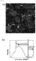
- FIG. 1 shows the merged image (a) according to Example 1 of the present disclosure and the histogram (b) obtained from the merged image.
- FIG. 2 shows the linear scale image (a) according to Comparative Example 1 and the histogram (b) obtained from the linear scale image.
- FIG. 3 shows the logarithmic scale image (a) according to Comparative Example 2 and the histogram (b) obtained from the logarithmic scale image.
- the conventional method of analyzing the electrode for a battery using only the linear scale image or the logarithmic scale image cannot accurately quantify the areas and distributions of the electrode active material region, the conductive material region and the pore region.
Landscapes
- General Physics & Mathematics (AREA)
- Physics & Mathematics (AREA)
- Engineering & Computer Science (AREA)
- General Health & Medical Sciences (AREA)
- Health & Medical Sciences (AREA)
- Chemical & Material Sciences (AREA)
- Nuclear Medicine, Radiotherapy & Molecular Imaging (AREA)
- Radiology & Medical Imaging (AREA)
- Theoretical Computer Science (AREA)
- General Chemical & Material Sciences (AREA)
- Electrochemistry (AREA)
- Chemical Kinetics & Catalysis (AREA)
- Materials Engineering (AREA)
- Life Sciences & Earth Sciences (AREA)
- Immunology (AREA)
- Pathology (AREA)
- Manufacturing & Machinery (AREA)
- Biochemistry (AREA)
- Analytical Chemistry (AREA)
- Computer Vision & Pattern Recognition (AREA)
- Quality & Reliability (AREA)
- Battery Electrode And Active Subsutance (AREA)
Abstract
Description
- The present application claims the benefit of the filing date of Korean Patent Application No.
10-2018-0125480 - The present disclosure relates to a method for analyzing an electrode for a battery.
- A secondary battery is generally composed of electrodes, a separator and an electrolyte, and the electrodes are classified into a negative electrode and a positive electrode. In the electrodes, constituent materials, including an active material, a conductive material and a binder, are three-dimensionally distributed, and thus many pores exist in the gaps therebetween. In order to improve the performance of the electrodes, it is very important to quantify and analyze the distribution of the constituent materials of the electrodes.
- In particular, since the conductive material may be easily distinguished only by its conductivity from the constituent materials of the electrodes, a quantification analysis method using scanning spreading resistance microscopy (SSRM) is used to distinguish the conductive material from the others.
- However, since the magnitude distribution of the resistance values of the constituent materials of the electrodes is very broad, a problem arises in that it is difficult to accurately distinguish the regions of the electrode constituent materials, such as the conductive material, the active material and the pores, from the data obtained by the SSRM of cross-sections of the electrodes.
- Accordingly, there is a need for a technology capable of more easily distinguishing between the constituent materials of the electrodes by the SSRM.
- The present disclosure intends to provide a method for analyzing an electrode for a battery, which is capable of more easily distinguishing the constituent materials of the electrode by scanning spreading resistance microscopy (SSRM).
- However, problems to be solved by the present disclosure are not limited to the above-mentioned problem, and other problems which are not mentioned will be clearly understood by those skilled in the art from the following description.
- One embodiment of the present disclosure provides a method for analyzing an electrode for a battery, the method including the steps of: preparing an electrode for a secondary battery including an electrode active material, a conductive material, and pores; preparing an electrode cross-section sample by irradiating the electrode for a secondary battery with an ion beam from an ion milling apparatus; obtaining resistance value data of the electrode active material, conductive material and pores of the electrode cross-section sample by scanning spreading resistance microscopy; obtaining a logarithmic scale image by changing the resistance value data to a logarithmic scale; obtaining a linear scale image by changing the resistance value data to a linear scale; and obtaining a merged image by merging the logarithmic scale image with the linear scale image.
- The method for analyzing an electrode for a battery according to one embodiment of the present disclosure has an advantage in that it is possible to easily distinguish between the constituent materials of the electrode, such as an electrode active material, a conductive material, and pores, by scanning spreading resistance microscopy.
- The effects of the present disclosure are not limited to the above-described effect, and effects which are not mentioned will be clearly understood by those skilled in the art from the present specification and the accompanying drawings.
-
-
FIG. 1 shows a merged image according to Example 1 of the present disclosure and a histogram obtained from the merged image. -
FIG. 2 shows a linear scale image according to Comparative Example 1 and a histogram obtained from the linear scale image. -
FIG. 3 shows a logarithmic scale image according to Comparative Example 2 and a histogram obtained from the logarithmic scale image. - Throughout the present specification, it is to be understood that when any part is referred to as "including" any component, it does not exclude other components, but may further include other components, unless otherwise specified.
- Throughout the present specification, when any member is referred to as being "on" another member, it refers to not only a case where any member is in contact with another member, but also a case where a third member exists between the two members.
- As used in the present specification, the term "step of doing ..." or "step of ..." does not mean "a step for ...".
- The present inventors have found that the magnitude of current values calculated using resistance values from the resistance value data of the electrode cross-section, obtained by scanning spreading resistance microscopy, has a distribution of 106 in the range of 10 pA to 10 µA, and when the resistance value data is displayed as an image, the scale of each pixel is displayed in 256 steps, and thus the distribution of the resistance values is displayed more compactly than the actual distribution, and different images are obtained depending on which of linear scale and logarithmic scale is used. Accordingly, there was difficulty in distinguishing between the regions of the constituent materials of the electrode by the magnitude of the resistance values.
- Specifically, it has been found that when the resistance values are changed to a linear scale and expressed as an image, the conductive material is easy to distinguish because a region (0.1 µA or more) clearly distinguished from the electrode active material or the pores exists in the image, but it is difficult to clearly distinguish the regions of the electrode active material and the pores. In addition, it has been found that when the resistance values are changed to a logarithmic scale and expressed as an image, the pores are easy to distinguish because a clearly distinguished region (0.1 µA or less) exists in the image, it is difficult to clearly distinguish the regions of the electrode material and the conductive material.
- Accordingly, the present inventors have found that when a logarithmic scale image obtained by changing resistance value data to a logarithmic scale is merged with a linear scale image obtained by changing the resistance value data to a linear scale and the resulting merged image is analyzed, the regions of the electrode active material, conductive materials and pores included in the electrode may be easily distinguished from one another, thereby completing the present disclosure as described below.
- Hereinafter, the present disclosure will be described in more detail.
- One embodiment of the present disclosure provides a method for analyzing an electrode for a battery, the method including the steps of: preparing an electrode for a secondary battery including an electrode active material, a conductive material, and pores; preparing an electrode cross-section sample by irradiating the electrode for a secondary battery with an ion beam from an ion milling apparatus; obtaining resistance value data of the electrode active material, conductive material and pores of the electrode cross-section sample by scanning spreading resistance microscopy; obtaining a logarithmic scale image by changing the resistance value data to a logarithmic scale; obtaining a linear scale image by changing the resistance value data to a linear scale; and obtaining a merged image by merging the logarithmic scale image with the linear scale image.
- The method for analyzing an electrode for a battery according to one embodiment of the present disclosure has an advantage in that it is capable of easily distinguishing between the constituent materials of the electrode, such as an electrode active material, a conductive material, and pores, by scanning spreading resistance microscopy.
- The method for analyzing an electrode for a battery according to one embodiment of the present disclosure may be for analyzing an electrode for a secondary battery. Specifically, the method for analyzing an electrode for a battery may be for analyzing a positive electrode for a secondary battery.
- According to one embodiment of the present disclosure, the electrode for a secondary battery includes an electrode active material, a conductive material, and pores. In addition, the electrode for a secondary battery may further include various additives such as a binder, which may improve the performance of the electrode. The electrode active material, the binder, the conductive material and the like are three-dimensionally distributed in the electrode for a secondary battery, and a large number of pores may exist in the gaps therebetween. That is, the constituent materials of the electrode, such as an electrode active material, a binder and a conductive material, as well as a large number of pores, may constitute the electrode for a secondary battery.
- As the electrode active material, the binder and the conductive material, which are included in the electrode for a secondary battery, materials that are commonly used in the art may be selected and used without particular limitation. Specifically, if the electrode for a secondary battery is a negative electrode, carboxymethyl cellulose (CMC), a diene-based binder such as butadiene, an acrylic-based binder, or the like may be used as the binder. In addition, as the negative electrode active material, there may be used various types of carbon-based materials including artificial graphite, natural graphite or hard carbon, non-carbon based materials containing silicon (Si), lithium titanium oxide (LTO), or the like, which can intercalate and deintercalate lithium.
- The method for analyzing an electrode for a battery according to one embodiment of the present disclosure may further include, before the step of preparing the electrode cross-section sample, a step of filling the pores in the electrode for a secondary battery with an epoxy group-containing polymer by impregnating the electrode for a secondary battery with the epoxy group-containing polymer.
- Specifically, the step of filling the pores in the electrode for a secondary battery with the epoxy group-containing polymer may include allowing the epoxy group-containing polymer to penetrate into the pores of the electrode for a secondary battery by impregnating the electrode for a secondary battery with the epoxy group-containing polymer. As the epoxy group-containing polymer, a liquid state polymer may be used. Using the epoxy group-containing liquid state polymer, the pores of the electrode for a secondary battery may be more effectively filled with the epoxy group-containing polymer. The process of impregnating the pores of the electrode for a secondary battery with the epoxy group-containing polymer may be carried out by a conventional method known in the art. For example, through a method of applying the epoxy group-containing polymer onto the electrode for a secondary battery or immersing the electrode for a secondary battery in a solution of the epoxy group-containing polymer, the pores of the electrode for a secondary battery may be impregnated with the epoxy group-containing polymer.
- According to one embodiment of the present disclosure, the method for analyzing the electrode for a battery may further include a step of measuring the resistance value of the epoxy group-containing polymer filling the pores of the electrode cross-section sample. As the pores in the electrode for a secondary battery are filled with the epoxy group-containing polymer, the resistance value of the pores in the electrode cross-section sample may be obtained by scanning spreading resistance microscopy. Specifically, resistance value data may be obtained by measuring the resistance value of the polymer material filling the pores. Through this, it is possible to identify the region where the pores are located, and it is possible to more accurately distinguish between the electrode active material region, the conductive material region and the pore region in the electrode cross-section sample from the merged image.
- According to one embodiment of the present disclosure, the epoxy group-containing polymer may be an epoxy group-containing polymer which is produced by a known method or commercially available. For example, the epoxy group-containing polymer may include at least one of epoxyethane(ethylene oxide), 1,3-epoxypropane(trimethylene oxide) and bisphenol-A-epichlorohydrin, but the kind of the epoxy group-containing polymer is not limited thereto. In addition, the epoxy group-containing polymer may have a weight-average molecular weight of 700 g/mol or less. Furthermore, a solution of the epoxy group-containing polymer may be used to fill the pores in the electrode for a secondary battery, and the solution of the epoxy group-containing polymer may include a curing agent in addition to the epoxy group-containing polymer.
- In addition, as the epoxy group-containing polymer, a polymer having two or more epoxy groups may be used. The epoxy group-containing polymer having two or more epoxy groups is a compound having two or more epoxy groups in the molecule. As the epoxy group-containing polymer, an aromatic or aliphatic epoxy group-containing polymer or a linear or branched epoxy group-containing polymer may be used. For example, an epoxy resin polymer including a cyclic structure in the molecular structure may be used. Specifically, an epoxy resin polymer including an aromatic group (e.g., a phenyl group) may be used. A specific example of the epoxy group-containing polymer including an aromatic group may be one or a mixture of two or more selected from among biphenyl-type epoxy group-containing polymers, dicyclopentadiene-type epoxy group-containing polymers, naphthalene-type epoxy group-containing polymers, dicyclopentadiene-modified phenol-type epoxy group-containing polymers, cresol-based epoxy group-containing polymers, bisphenol-based epoxy group-containing polymers, xyloxy-based epoxy group-containing polymers, polyfunctional epoxy group-containing polymers, phenol novolak epoxy group-containing polymers, triphenolmethane type epoxy group-containing polymers, and alkyl-modified triphenolmethane epoxy group-containing polymers, but is not limited thereto.
- According to one embodiment of the present disclosure, the electrode materials may be sputtered by irradiating the electrode for a secondary battery with an ion beam generated in an ion gun of an ion milling apparatus. Through this, it is possible to prepare an electrode cross-section sample having a clean cross-section without physical damage. As the electrode cross-section sample has a clean cross-section without physical damage, the pores, the electrode active material and the binder in the electrode for a secondary battery may be more clearly distinguished from one another.
- According to one embodiment of the present disclosure, the ion beam may be an argon ion beam. As the electrode for a secondary battery is irradiated with the argon ion beam, the electrode cross-section sample may be more stably prepared.
- According to one embodiment of the present disclosure, the ion beam current of the ion milling apparatus may be 100 µA to 250 µA. Specifically, the ion beam current of the ion milling apparatus may be 110 µA to 150 µA, or 200 µA to 230 µA. As the ion beam current of the ion milling apparatus is adjusted within the above range, the preparation time of the electrode cross-section sample may be shortened, and an electrode cross-section sample having a cleaner cross-section may be prepared by preventing the electrode materials from being re-deposited on the cross-section of the sample. Through this, it is possible to more accurately calculate the coverage of the electrode active material of the electrode for a secondary battery.
- According to one embodiment of the present disclosure, the discharge current of the ion milling apparatus may be 250 µA to 450 µA. Specifically, the discharge current of the ion milling apparatus may be 370 µA to 450 µA, or 400 µA to 430 µA. As the discharge current of the ion milling apparatus is adjusted within the above-described range, the operational efficiency of the ion milling apparatus may be prevented from decreasing, and the preparation time of the electrode cross-section sample may be minimized.
- According to one embodiment of the present disclosure, the distribution of the resistance values of each of the electrode active material, conductive material and pores included in the electrode cross-section sample may be measured two-dimensionally by analyzing the electrode cross-section sample using scanning spreading resistance microscopy, an image may be obtained by visualizing the distribution, and resistance value data including these resistance values may be obtained.
- According to one embodiment of the present disclosure, the electrode cross-section sample according to one embodiment of the present disclosure may be analyzed under the driving conditions of a scanning spreading resistance microscope for analyzing electrode cross-section samples in the art. For example, in the present disclosure, an NX-10 AFM system (Park Systems) equipped with an SSRM module may be used as the scanning spreading resistance microscope, and SmartScan (Park Systems) may be used as measurement software. As specific driving conditions, the contact mode may be set, and the image pixels to be obtained may be set to 1024 X 1024, the scan rate may be set to 0.2 Hz to 0.25 Hz, the bias may be set to 2.0 V or less, and the set point may be set to 1.0 V or less.
- In addition, as the probes of the AFM, there may be used solid diamond AFM probes (IMEC) which each have a length of 465 µm, a width of 50 µm and a thickness of 5 µm and are made of B-doped polycrystalline diamond.
- According to one embodiment of the present disclosure, the resistance value data obtained by the scanning spreading resistance microscopy may be processed and changed to a logarithmic scale to obtain a logarithmic scale image. In addition, the resistance value data obtained by the scanning spreading resistance microscopy may be processed and changed to a linear scale to obtain a linear scale image.
- As described above, in the case of the logarithmic scale image, it is not easy to distinguish between the electrode active material and the conductive material, and in the case of the linear scale image, it is not easy to distinguish between the electrode active material and the pores.
- However, the method for analyzing an electrode for a battery according to one embodiment of the present disclosure has an advantage in that it can more clearly distinguish between the electrode active material, the conductive material and the pores, which are included in the electrode cross-section sample, by analyzing the merged image obtained by merging the logarithmic scale image and linear scale image obtained from the resistance value data.
- According to one embodiment of the present disclosure, the method for analyzing an electrode for a battery may further include a step of distinguishing between and quantifying the electrode active material region, the conductive material region and the pore region in the electrode cross-section sample by analyzing the merged image. In addition, the method for analyzing an electrode for a battery may further include a step of distinguishing between and quantifying the electrode active material region, the conductive material region, the pore region and the binder region in the electrode cross-section sample by analyzing the merged image.
- According to one embodiment of the present disclosure, the step of quantifying may include a step of obtaining a histogram in which materials constituting the electrode cross-section sample are displayed separately, by analyzing the merged image. Specifically, it is possible to determine whether a region corresponding to each pixel on the obtained histogram is the electrode active material region, the conductive material region or the pore region. Using information of each pixel whose corresponding region was determined, it is possible to easily quantify the areas and distributions of the electrode active material region, the conductive material region and the pore region in the merged image.
- Hereinafter, the present disclosure will be described in detail with reference to examples. However, the examples according to the present disclosure may be modified into various different forms, and the scope of the present disclosure is not interpreted as being limited to the examples described below. The examples of the present specification are provided to more completely explain the present disclosure to those skilled in the art.
- A positive electrode for a secondary battery (LG Chem., Ltd.) was prepared which includes a positive electrode active material (NCM622, Nichia) and a conductive material (FX35, Denka). In addition, as an epoxy group-containing polymer, a solution containing an epoxy-based polymer having a weight-average molecular weight of about 700 g/mol or less was prepared. The positive electrode for a secondary battery was immersed in the prepared epoxy-based polymer solution to fill the pores of the positive electrode for a secondary battery with the epoxy group-containing polymer. Then, the surface of the positive electrode for a secondary battery was cut off by irradiation with a focused argon (Ar) ion beam from an ion milling device (IM 4000, Hitachi) that emits an argon ion beam, thereby preparing a positive electrode cross-section sample having a clean cross-section. The argon ion beam irradiation was performed at a discharge current of 400 µA, an ion beam current of 130 µA and a gas flow rate of 1 cm3/min for 3 hours.
- Using a scanning spreading resistance microscope (NX-10 AFM system; Park Systems), the resistance value of the positive electrode active material, the resistance value of the conductive material and the resistance value of the epoxy group-containing polymer filling the pores were measured from the prepared positive electrode cross-section sample. At this time, as the driving conditions of the scanning spreading resistance microscope, the contact mode was set, the image pixels to be obtained were set to 1024 X 1024, the scan rate was set to 0.2 Hz, the bias was set to 2.0 V, and the set point was set to 1.0 V.
- Thereafter, using the XEI software (Park Systems) included in the scanning spreading resistance microscope, the obtained resistance value data were changed to a logarithmic scale to obtain a logarithmic scale image, and the resistance value data were changed to a linear scale to obtain a linear scale image.
- Next, using the Avizo software (FEI), the obtained logarithmic scale image and linear scale image were merged with each other to obtain a merged image, and a histogram was obtained from the merged image.
- A positive electrode cross-section sample was prepared in the same manner as Example 1 above, and resistance value data were obtained using a scanning spreading resistance microscope. Then, the obtained resistance value data were changed to a linear scale to obtain a linear scale image in the same manner as Example 1 above, and a histogram was obtained from the linear scale image.
- A positive electrode cross-section sample was prepared in the same manner as Example 1 above, and resistance value data were obtained using a scanning spreading resistance microscope. Then, the obtained resistance value data were changed to a logarithmic scale to obtain a logarithmic scale image in the same manner as Example 1 above, and a histogram was obtained from the logarithmic scale image.
-
FIG. 1 shows the merged image (a) according to Example 1 of the present disclosure and the histogram (b) obtained from the merged image. Furthermore,FIG. 2 shows the linear scale image (a) according to Comparative Example 1 and the histogram (b) obtained from the linear scale image. In addition,FIG. 3 shows the logarithmic scale image (a) according to Comparative Example 2 and the histogram (b) obtained from the logarithmic scale image. - Referring to
FIG. 1 , it was confirmed that, on the histogram obtained from the merged image obtained by merging the logarithmic scale image with the linear scale image, the pixels corresponding to the positive electrode active material, the conductive material and the pores, respectively, were clearly distinguished from one another. That is, it can be seen that the areas and distributions of the electrode active material region, the conductive material region and the pore region in the merged image can be easily quantified using information of each pixel whose corresponding region was determined. - On the contrary, referring to
FIG. 2 , it was confirmed that, on the histogram obtained from the linear scale image, the pixels corresponding to the positive electrode active material and the pores, respectively, were not clearly distinguished from each other. In addition, referring toFIG. 3 , it was confirmed that, on the histogram obtained from the logarithmic scale image, the pixels corresponding to the positive electrode active material and the conductive material, respectively, were not clearly distinguished from each other. - That is, it can be seen that the conventional method of analyzing the electrode for a battery using only the linear scale image or the logarithmic scale image cannot accurately quantify the areas and distributions of the electrode active material region, the conductive material region and the pore region.
Claims (6)
- A method for analyzing an electrode for a battery, the method comprising the steps of:preparing an electrode for a secondary battery comprising an electrode active material, a conductive material, and pores;preparing an electrode cross-section sample by irradiating the electrode for a secondary battery with an ion beam from an ion milling apparatus;obtaining resistance value data of the electrode active material, the conductive material and the pores in the electrode cross-section sample by scanning spreading resistance microscopy;obtaining a logarithmic scale image by changing the resistance value data to a logarithmic scale;obtaining a linear scale image by changing the resistance value data to a linear scale; andobtaining a merged image by merging the logarithmic scale image with the linear scale image.
- The method of claim 1, further comprising a step of distinguishing between and quantifying a region of the electrode active material, a region of the conductive material and a region of the pores in the electrode cross-section sample, by analyzing the merged image.
- The method of claim 1, further comprising, before the step of preparing the electrode cross-section sample, a step of filling pores in the electrode for a secondary battery with an epoxy group-containing polymer by impregnating the electrode for a secondary battery with the epoxy group-containing polymer.
- The method of claim 3, further comprising a step of measuring a resistance value of the epoxy group-containing polymer filling the pores of the electrode cross-section sample.
- The method of claim 1, wherein the ion beam is an argon ion beam.
- The method of claim 1, wherein an ion beam current of the ion milling apparatus is 100 µA to 250 µA.
Applications Claiming Priority (2)
| Application Number | Priority Date | Filing Date | Title |
|---|---|---|---|
| KR1020180125480A KR102460016B1 (en) | 2018-10-19 | 2018-10-19 | Method for analysis of battery electrode |
| PCT/KR2019/013507 WO2020080793A1 (en) | 2018-10-19 | 2019-10-15 | Battery electrode analysis method |
Publications (3)
| Publication Number | Publication Date |
|---|---|
| EP3786646A1 true EP3786646A1 (en) | 2021-03-03 |
| EP3786646A4 EP3786646A4 (en) | 2021-07-21 |
| EP3786646B1 EP3786646B1 (en) | 2023-11-29 |
Family
ID=70284016
Family Applications (1)
| Application Number | Title | Priority Date | Filing Date |
|---|---|---|---|
| EP19874260.3A Active EP3786646B1 (en) | 2018-10-19 | 2019-10-15 | Battery electrode analysis method |
Country Status (9)
| Country | Link |
|---|---|
| US (1) | US11650223B2 (en) |
| EP (1) | EP3786646B1 (en) |
| JP (1) | JP6988042B2 (en) |
| KR (1) | KR102460016B1 (en) |
| CN (1) | CN112189142B (en) |
| ES (1) | ES2971072T3 (en) |
| HU (1) | HUE065324T2 (en) |
| PL (1) | PL3786646T3 (en) |
| WO (1) | WO2020080793A1 (en) |
Families Citing this family (2)
| Publication number | Priority date | Publication date | Assignee | Title |
|---|---|---|---|---|
| CN111693736B (en) * | 2020-06-22 | 2023-05-12 | 湘潭大学 | Section sample of lithium ion battery electrode plate for atomic force microscope characterization and preparation method thereof |
| WO2023204649A1 (en) * | 2022-04-20 | 2023-10-26 | 주식회사 엘지에너지솔루션 | Dry electrode comprising mixture powder for electrode |
Family Cites Families (22)
| Publication number | Priority date | Publication date | Assignee | Title |
|---|---|---|---|---|
| JP2005295497A (en) * | 2004-03-10 | 2005-10-20 | Seiko Epson Corp | Image quality display device, digital camera, developing apparatus, image quality display method and image quality display program |
| US7344677B2 (en) * | 2004-04-02 | 2008-03-18 | Ovonic Battery Company, Inc. | Hydrogen storage alloys having improved cycle life and low temperature operating characteristics |
| JP2007123207A (en) | 2005-10-31 | 2007-05-17 | Mitsui Mining & Smelting Co Ltd | Evaluation method of electrode for battery |
| CN100570348C (en) * | 2006-09-28 | 2009-12-16 | 韶关学院 | The comprehensive analysis method of electrochemical impedance spectrum of metal material surface characteristics |
| AU2008216170B2 (en) * | 2007-02-14 | 2012-07-26 | Otsuka Pharmaceutical Co., Ltd. | In-body power source having high surface area electrode |
| CN101493503B (en) * | 2009-02-26 | 2011-09-07 | 韶关学院 | Method for characterizing battery by electrochemical impedance spectrum |
| JP2014203665A (en) * | 2013-04-04 | 2014-10-27 | 本田技研工業株式会社 | Method and device for quantification of electrode material |
| JP5815617B2 (en) | 2013-08-20 | 2015-11-17 | 株式会社住化分析センター | Electrode evaluation method and manufacturing method |
| JP6473924B2 (en) | 2014-12-03 | 2019-02-27 | 東芝Itコントロールシステム株式会社 | Battery inspection device |
| KR20160149450A (en) * | 2015-06-18 | 2016-12-28 | 주식회사 엘지화학 | Method for analyzing content or distribution of metal in secondary battery cathode active material |
| KR102048342B1 (en) * | 2015-07-09 | 2019-11-25 | 주식회사 엘지화학 | A method for analyzing pore distribution in secondary battery cathode and polymer therefor |
| KR20170019146A (en) * | 2015-08-11 | 2017-02-21 | 주식회사 엘지화학 | A method for analyzing distribution of components and pores in secondary battery electrode and composition therefor |
| WO2017046915A1 (en) * | 2015-09-17 | 2017-03-23 | 株式会社東芝 | Composite electrolyte for secondary batteries, secondary battery and battery pack |
| US11013680B2 (en) | 2016-03-30 | 2021-05-25 | Kose Corporation | Makeup-protecting material |
| JP6703673B2 (en) * | 2016-05-17 | 2020-06-03 | 株式会社 空スペース | Flywheel device for power storage |
| CN108292751B (en) * | 2016-05-30 | 2021-06-04 | 日立金属株式会社 | Positive electrode active material for lithium ion secondary battery and lithium ion secondary battery using same |
| KR102068764B1 (en) * | 2016-07-05 | 2020-01-21 | 주식회사 엘지화학 | Method and system for observing pore distribution within the battery anode |
| JP6696692B2 (en) * | 2016-09-20 | 2020-05-20 | 株式会社東芝 | Electrodes, non-aqueous electrolyte batteries, battery packs and vehicles |
| JP2018109577A (en) * | 2017-01-05 | 2018-07-12 | 国立研究開発法人産業技術総合研究所 | Analyzer |
| US11837730B2 (en) | 2017-03-13 | 2023-12-05 | Toray Industries, Inc. | Secondary battery electrode |
| JP6911676B2 (en) | 2017-03-24 | 2021-07-28 | 住友金属鉱山株式会社 | Evaluation method of positive electrode active material for lithium ion secondary battery |
| US11673623B2 (en) * | 2020-04-08 | 2023-06-13 | Rekluse Racing Llc | Master cylinder |
-
2018
- 2018-10-19 KR KR1020180125480A patent/KR102460016B1/en active IP Right Grant
-
2019
- 2019-10-15 EP EP19874260.3A patent/EP3786646B1/en active Active
- 2019-10-15 HU HUE19874260A patent/HUE065324T2/en unknown
- 2019-10-15 ES ES19874260T patent/ES2971072T3/en active Active
- 2019-10-15 US US15/734,784 patent/US11650223B2/en active Active
- 2019-10-15 PL PL19874260.3T patent/PL3786646T3/en unknown
- 2019-10-15 JP JP2020565391A patent/JP6988042B2/en active Active
- 2019-10-15 CN CN201980034640.5A patent/CN112189142B/en active Active
- 2019-10-15 WO PCT/KR2019/013507 patent/WO2020080793A1/en unknown
Also Published As
| Publication number | Publication date |
|---|---|
| US11650223B2 (en) | 2023-05-16 |
| CN112189142B (en) | 2023-12-05 |
| JP6988042B2 (en) | 2022-01-05 |
| WO2020080793A1 (en) | 2020-04-23 |
| JP2021526712A (en) | 2021-10-07 |
| HUE065324T2 (en) | 2024-05-28 |
| US20210231704A1 (en) | 2021-07-29 |
| KR102460016B1 (en) | 2022-10-28 |
| EP3786646A4 (en) | 2021-07-21 |
| PL3786646T3 (en) | 2024-05-13 |
| CN112189142A (en) | 2021-01-05 |
| EP3786646B1 (en) | 2023-11-29 |
| KR20200044550A (en) | 2020-04-29 |
| ES2971072T3 (en) | 2024-06-03 |
Similar Documents
| Publication | Publication Date | Title |
|---|---|---|
| Padgett et al. | Connecting fuel cell catalyst nanostructure and accessibility using quantitative cryo-STEM tomography | |
| Seidl et al. | In situ scanning tunneling microscopy studies of the SEI formation on graphite electrodes for Li+-ion batteries | |
| KR102606425B1 (en) | Method for performance analysis of secondary battery electrode | |
| US11650223B2 (en) | Battery electrode analysis method | |
| Cantoni et al. | Advances in 3D focused ion beam tomography | |
| Fletcher | Latest applications of 3D ToF-SIMS bio-imaging | |
| Guetaz et al. | Catalyst-layer ionomer imaging of fuel cells | |
| CN110352347B (en) | Method for measuring pore distribution in electrode for secondary battery | |
| CN103196728A (en) | Method for preparing scanning electron microscope (SEM) sample or transmission electron microscope (TEM) sample protection layer by using focused ion beam (FIB) technology | |
| KR102068764B1 (en) | Method and system for observing pore distribution within the battery anode | |
| Pan et al. | Fast Li plating behavior probed by X-ray computed tomography | |
| Martín‐Yerga et al. | Scanning electrochemical cell microscopy in a glovebox: structure‐activity correlations in the early stages of solid‐electrolyte interphase formation on graphite | |
| KR102048342B1 (en) | A method for analyzing pore distribution in secondary battery cathode and polymer therefor | |
| Mahbub et al. | A method for quantitative 3D mesoscale analysis of solid oxide fuel cell microstructures using Xe-plasma focused ion beam (PFIB) coupled with SEM | |
| Muramoto et al. | ToF‐SIMS depth profiling of trehalose: the effect of analysis beam dose on the quality of depth profiles | |
| US9261531B2 (en) | Quantification method and quantification apparatus for electrode material | |
| Kim et al. | A new mechanism of stabilizing SEI of Si anode driven by crosstalk behavior and its potential for developing high performance Si-based batteries | |
| CN108088864B (en) | Method and system for reconstructing three-dimensional microstructure of material | |
| KR20170019146A (en) | A method for analyzing distribution of components and pores in secondary battery electrode and composition therefor | |
| Yang et al. | Integrated tungsten nanofiber field emission cathodes selectively grown by nanoscale electron beam-induced deposition | |
| CN104425297B (en) | Method for analyzing chip failure and chip failure evaluation of markers | |
| CN108519396A (en) | A kind of preparation method of ultra-thin section | |
| Chen‐Wiegart et al. | Sample Preparation of Energy Materials for X‐ray Nanotomography with Micromanipulation | |
| WO2010132221A4 (en) | Gas field ion microscopes having multiple operation modes | |
| Sabharwal et al. | Improving FIB-SEM reconstructions by using epoxy resin embedding |
Legal Events
| Date | Code | Title | Description |
|---|---|---|---|
| STAA | Information on the status of an ep patent application or granted ep patent |
Free format text: STATUS: THE INTERNATIONAL PUBLICATION HAS BEEN MADE |
|
| STAA | Information on the status of an ep patent application or granted ep patent |
Free format text: STATUS: THE INTERNATIONAL PUBLICATION HAS BEEN MADE |
|
| PUAI | Public reference made under article 153(3) epc to a published international application that has entered the european phase |
Free format text: ORIGINAL CODE: 0009012 |
|
| STAA | Information on the status of an ep patent application or granted ep patent |
Free format text: STATUS: REQUEST FOR EXAMINATION WAS MADE |
|
| 17P | Request for examination filed |
Effective date: 20201124 |
|
| AK | Designated contracting states |
Kind code of ref document: A1 Designated state(s): AL AT BE BG CH CY CZ DE DK EE ES FI FR GB GR HR HU IE IS IT LI LT LU LV MC MK MT NL NO PL PT RO RS SE SI SK SM TR |
|
| AX | Request for extension of the european patent |
Extension state: BA ME |
|
| A4 | Supplementary search report drawn up and despatched |
Effective date: 20210622 |
|
| RIC1 | Information provided on ipc code assigned before grant |
Ipc: G01Q 30/20 20100101AFI20210616BHEP Ipc: G01Q 30/04 20100101ALI20210616BHEP Ipc: G06T 1/00 20060101ALI20210616BHEP Ipc: G06T 5/50 20060101ALI20210616BHEP Ipc: G01N 1/44 20060101ALI20210616BHEP Ipc: H01M 4/13 20100101ALI20210616BHEP Ipc: G01Q 60/30 20100101ALI20210616BHEP |
|
| RAP1 | Party data changed (applicant data changed or rights of an application transferred) |
Owner name: LG ENERGY SOLUTION LTD. |
|
| DAV | Request for validation of the european patent (deleted) | ||
| DAX | Request for extension of the european patent (deleted) | ||
| RAP3 | Party data changed (applicant data changed or rights of an application transferred) |
Owner name: LG ENERGY SOLUTION, LTD. |
|
| GRAP | Despatch of communication of intention to grant a patent |
Free format text: ORIGINAL CODE: EPIDOSNIGR1 |
|
| STAA | Information on the status of an ep patent application or granted ep patent |
Free format text: STATUS: GRANT OF PATENT IS INTENDED |
|
| INTG | Intention to grant announced |
Effective date: 20230622 |
|
| GRAS | Grant fee paid |
Free format text: ORIGINAL CODE: EPIDOSNIGR3 |
|
| P01 | Opt-out of the competence of the unified patent court (upc) registered |
Effective date: 20230919 |
|
| GRAA | (expected) grant |
Free format text: ORIGINAL CODE: 0009210 |
|
| STAA | Information on the status of an ep patent application or granted ep patent |
Free format text: STATUS: THE PATENT HAS BEEN GRANTED |
|
| AK | Designated contracting states |
Kind code of ref document: B1 Designated state(s): AL AT BE BG CH CY CZ DE DK EE ES FI FR GB GR HR HU IE IS IT LI LT LU LV MC MK MT NL NO PL PT RO RS SE SI SK SM TR |
|
| REG | Reference to a national code |
Ref country code: GB Ref legal event code: FG4D |
|
| REG | Reference to a national code |
Ref country code: CH Ref legal event code: EP |
|
| REG | Reference to a national code |
Ref country code: DE Ref legal event code: R096 Ref document number: 602019042581 Country of ref document: DE |
|
| REG | Reference to a national code |
Ref country code: IE Ref legal event code: FG4D |
|
| REG | Reference to a national code |
Ref country code: SE Ref legal event code: TRGR |
|
| REG | Reference to a national code |
Ref country code: LT Ref legal event code: MG9D |
|
| REG | Reference to a national code |
Ref country code: NL Ref legal event code: MP Effective date: 20231129 |
|
| PG25 | Lapsed in a contracting state [announced via postgrant information from national office to epo] |
Ref country code: GR Free format text: LAPSE BECAUSE OF FAILURE TO SUBMIT A TRANSLATION OF THE DESCRIPTION OR TO PAY THE FEE WITHIN THE PRESCRIBED TIME-LIMIT Effective date: 20240301 |
|
| PG25 | Lapsed in a contracting state [announced via postgrant information from national office to epo] |
Ref country code: IS Free format text: LAPSE BECAUSE OF FAILURE TO SUBMIT A TRANSLATION OF THE DESCRIPTION OR TO PAY THE FEE WITHIN THE PRESCRIBED TIME-LIMIT Effective date: 20240329 |
|
| PG25 | Lapsed in a contracting state [announced via postgrant information from national office to epo] |
Ref country code: LT Free format text: LAPSE BECAUSE OF FAILURE TO SUBMIT A TRANSLATION OF THE DESCRIPTION OR TO PAY THE FEE WITHIN THE PRESCRIBED TIME-LIMIT Effective date: 20231129 |
|
| PG25 | Lapsed in a contracting state [announced via postgrant information from national office to epo] |
Ref country code: LT Free format text: LAPSE BECAUSE OF FAILURE TO SUBMIT A TRANSLATION OF THE DESCRIPTION OR TO PAY THE FEE WITHIN THE PRESCRIBED TIME-LIMIT Effective date: 20231129 Ref country code: IS Free format text: LAPSE BECAUSE OF FAILURE TO SUBMIT A TRANSLATION OF THE DESCRIPTION OR TO PAY THE FEE WITHIN THE PRESCRIBED TIME-LIMIT Effective date: 20240329 Ref country code: GR Free format text: LAPSE BECAUSE OF FAILURE TO SUBMIT A TRANSLATION OF THE DESCRIPTION OR TO PAY THE FEE WITHIN THE PRESCRIBED TIME-LIMIT Effective date: 20240301 Ref country code: BG Free format text: LAPSE BECAUSE OF FAILURE TO SUBMIT A TRANSLATION OF THE DESCRIPTION OR TO PAY THE FEE WITHIN THE PRESCRIBED TIME-LIMIT Effective date: 20240229 |
|
| REG | Reference to a national code |
Ref country code: AT Ref legal event code: MK05 Ref document number: 1636661 Country of ref document: AT Kind code of ref document: T Effective date: 20231129 |
|
| PG25 | Lapsed in a contracting state [announced via postgrant information from national office to epo] |
Ref country code: NL Free format text: LAPSE BECAUSE OF FAILURE TO SUBMIT A TRANSLATION OF THE DESCRIPTION OR TO PAY THE FEE WITHIN THE PRESCRIBED TIME-LIMIT Effective date: 20231129 |
|
| REG | Reference to a national code |
Ref country code: HU Ref legal event code: AG4A Ref document number: E065324 Country of ref document: HU |
|
| PG25 | Lapsed in a contracting state [announced via postgrant information from national office to epo] |
Ref country code: RS Free format text: LAPSE BECAUSE OF FAILURE TO SUBMIT A TRANSLATION OF THE DESCRIPTION OR TO PAY THE FEE WITHIN THE PRESCRIBED TIME-LIMIT Effective date: 20231129 Ref country code: NO Free format text: LAPSE BECAUSE OF FAILURE TO SUBMIT A TRANSLATION OF THE DESCRIPTION OR TO PAY THE FEE WITHIN THE PRESCRIBED TIME-LIMIT Effective date: 20240229 Ref country code: NL Free format text: LAPSE BECAUSE OF FAILURE TO SUBMIT A TRANSLATION OF THE DESCRIPTION OR TO PAY THE FEE WITHIN THE PRESCRIBED TIME-LIMIT Effective date: 20231129 Ref country code: LV Free format text: LAPSE BECAUSE OF FAILURE TO SUBMIT A TRANSLATION OF THE DESCRIPTION OR TO PAY THE FEE WITHIN THE PRESCRIBED TIME-LIMIT Effective date: 20231129 Ref country code: HR Free format text: LAPSE BECAUSE OF FAILURE TO SUBMIT A TRANSLATION OF THE DESCRIPTION OR TO PAY THE FEE WITHIN THE PRESCRIBED TIME-LIMIT Effective date: 20231129 |
|
| REG | Reference to a national code |
Ref country code: ES Ref legal event code: FG2A Ref document number: 2971072 Country of ref document: ES Kind code of ref document: T3 Effective date: 20240603 |
|
| PG25 | Lapsed in a contracting state [announced via postgrant information from national office to epo] |
Ref country code: DK Free format text: LAPSE BECAUSE OF FAILURE TO SUBMIT A TRANSLATION OF THE DESCRIPTION OR TO PAY THE FEE WITHIN THE PRESCRIBED TIME-LIMIT Effective date: 20231129 |
|
| PG25 | Lapsed in a contracting state [announced via postgrant information from national office to epo] |
Ref country code: CZ Free format text: LAPSE BECAUSE OF FAILURE TO SUBMIT A TRANSLATION OF THE DESCRIPTION OR TO PAY THE FEE WITHIN THE PRESCRIBED TIME-LIMIT Effective date: 20231129 Ref country code: AT Free format text: LAPSE BECAUSE OF FAILURE TO SUBMIT A TRANSLATION OF THE DESCRIPTION OR TO PAY THE FEE WITHIN THE PRESCRIBED TIME-LIMIT Effective date: 20231129 |
|
| PG25 | Lapsed in a contracting state [announced via postgrant information from national office to epo] |
Ref country code: SK Free format text: LAPSE BECAUSE OF FAILURE TO SUBMIT A TRANSLATION OF THE DESCRIPTION OR TO PAY THE FEE WITHIN THE PRESCRIBED TIME-LIMIT Effective date: 20231129 |
|
| PG25 | Lapsed in a contracting state [announced via postgrant information from national office to epo] |
Ref country code: SM Free format text: LAPSE BECAUSE OF FAILURE TO SUBMIT A TRANSLATION OF THE DESCRIPTION OR TO PAY THE FEE WITHIN THE PRESCRIBED TIME-LIMIT Effective date: 20231129 Ref country code: SK Free format text: LAPSE BECAUSE OF FAILURE TO SUBMIT A TRANSLATION OF THE DESCRIPTION OR TO PAY THE FEE WITHIN THE PRESCRIBED TIME-LIMIT Effective date: 20231129 Ref country code: RO Free format text: LAPSE BECAUSE OF FAILURE TO SUBMIT A TRANSLATION OF THE DESCRIPTION OR TO PAY THE FEE WITHIN THE PRESCRIBED TIME-LIMIT Effective date: 20231129 Ref country code: IT Free format text: LAPSE BECAUSE OF FAILURE TO SUBMIT A TRANSLATION OF THE DESCRIPTION OR TO PAY THE FEE WITHIN THE PRESCRIBED TIME-LIMIT Effective date: 20231129 Ref country code: EE Free format text: LAPSE BECAUSE OF FAILURE TO SUBMIT A TRANSLATION OF THE DESCRIPTION OR TO PAY THE FEE WITHIN THE PRESCRIBED TIME-LIMIT Effective date: 20231129 Ref country code: DK Free format text: LAPSE BECAUSE OF FAILURE TO SUBMIT A TRANSLATION OF THE DESCRIPTION OR TO PAY THE FEE WITHIN THE PRESCRIBED TIME-LIMIT Effective date: 20231129 Ref country code: CZ Free format text: LAPSE BECAUSE OF FAILURE TO SUBMIT A TRANSLATION OF THE DESCRIPTION OR TO PAY THE FEE WITHIN THE PRESCRIBED TIME-LIMIT Effective date: 20231129 Ref country code: AT Free format text: LAPSE BECAUSE OF FAILURE TO SUBMIT A TRANSLATION OF THE DESCRIPTION OR TO PAY THE FEE WITHIN THE PRESCRIBED TIME-LIMIT Effective date: 20231129 |
|
| PG25 | Lapsed in a contracting state [announced via postgrant information from national office to epo] |
Ref country code: PT Free format text: LAPSE BECAUSE OF FAILURE TO SUBMIT A TRANSLATION OF THE DESCRIPTION OR TO PAY THE FEE WITHIN THE PRESCRIBED TIME-LIMIT Effective date: 20240401 |
|
| PG25 | Lapsed in a contracting state [announced via postgrant information from national office to epo] |
Ref country code: PT Free format text: LAPSE BECAUSE OF FAILURE TO SUBMIT A TRANSLATION OF THE DESCRIPTION OR TO PAY THE FEE WITHIN THE PRESCRIBED TIME-LIMIT Effective date: 20240401 |