EP3786622B1 - Abbildungssystem und -verfahren für industrielle ausrüstungen - Google Patents
Abbildungssystem und -verfahren für industrielle ausrüstungen Download PDFInfo
- Publication number
- EP3786622B1 EP3786622B1 EP18916859.4A EP18916859A EP3786622B1 EP 3786622 B1 EP3786622 B1 EP 3786622B1 EP 18916859 A EP18916859 A EP 18916859A EP 3786622 B1 EP3786622 B1 EP 3786622B1
- Authority
- EP
- European Patent Office
- Prior art keywords
- radiation
- industrial equipment
- source
- detector
- energy
- Prior art date
- Legal status (The legal status is an assumption and is not a legal conclusion. Google has not performed a legal analysis and makes no representation as to the accuracy of the status listed.)
- Active
Links
Images


Classifications
-
- G—PHYSICS
- G01—MEASURING; TESTING
- G01T—MEASUREMENT OF NUCLEAR OR X-RADIATION
- G01T1/00—Measuring X-radiation, gamma radiation, corpuscular radiation, or cosmic radiation
- G01T1/29—Measurement performed on radiation beams, e.g. position or section of the beam; Measurement of spatial distribution of radiation
- G01T1/2914—Measurement of spatial distribution of radiation
- G01T1/2985—In depth localisation, e.g. using positron emitters; Tomographic imaging (longitudinal and transverse section imaging; apparatus for radiation diagnosis sequentially in different planes, steroscopic radiation diagnosis)
-
- G—PHYSICS
- G01—MEASURING; TESTING
- G01N—INVESTIGATING OR ANALYSING MATERIALS BY DETERMINING THEIR CHEMICAL OR PHYSICAL PROPERTIES
- G01N23/00—Investigating or analysing materials by the use of wave or particle radiation, e.g. X-rays or neutrons, not covered by groups G01N3/00 – G01N17/00, G01N21/00 or G01N22/00
- G01N23/02—Investigating or analysing materials by the use of wave or particle radiation, e.g. X-rays or neutrons, not covered by groups G01N3/00 – G01N17/00, G01N21/00 or G01N22/00 by transmitting the radiation through the material
- G01N23/04—Investigating or analysing materials by the use of wave or particle radiation, e.g. X-rays or neutrons, not covered by groups G01N3/00 – G01N17/00, G01N21/00 or G01N22/00 by transmitting the radiation through the material and forming images of the material
- G01N23/046—Investigating or analysing materials by the use of wave or particle radiation, e.g. X-rays or neutrons, not covered by groups G01N3/00 – G01N17/00, G01N21/00 or G01N22/00 by transmitting the radiation through the material and forming images of the material using tomography, e.g. computed tomography [CT]
-
- G—PHYSICS
- G01—MEASURING; TESTING
- G01T—MEASUREMENT OF NUCLEAR OR X-RADIATION
- G01T1/00—Measuring X-radiation, gamma radiation, corpuscular radiation, or cosmic radiation
- G01T1/29—Measurement performed on radiation beams, e.g. position or section of the beam; Measurement of spatial distribution of radiation
-
- G—PHYSICS
- G01—MEASURING; TESTING
- G01N—INVESTIGATING OR ANALYSING MATERIALS BY DETERMINING THEIR CHEMICAL OR PHYSICAL PROPERTIES
- G01N2223/00—Investigating materials by wave or particle radiation
- G01N2223/40—Imaging
- G01N2223/401—Imaging image processing
-
- G—PHYSICS
- G01—MEASURING; TESTING
- G01N—INVESTIGATING OR ANALYSING MATERIALS BY DETERMINING THEIR CHEMICAL OR PHYSICAL PROPERTIES
- G01N2223/00—Investigating materials by wave or particle radiation
- G01N2223/40—Imaging
- G01N2223/419—Imaging computed tomograph
-
- G—PHYSICS
- G01—MEASURING; TESTING
- G01N—INVESTIGATING OR ANALYSING MATERIALS BY DETERMINING THEIR CHEMICAL OR PHYSICAL PROPERTIES
- G01N2223/00—Investigating materials by wave or particle radiation
- G01N2223/40—Imaging
- G01N2223/423—Imaging multispectral imaging-multiple energy imaging
-
- G—PHYSICS
- G01—MEASURING; TESTING
- G01N—INVESTIGATING OR ANALYSING MATERIALS BY DETERMINING THEIR CHEMICAL OR PHYSICAL PROPERTIES
- G01N2223/00—Investigating materials by wave or particle radiation
- G01N2223/60—Specific applications or type of materials
- G01N2223/601—Specific applications or type of materials density profile
-
- G—PHYSICS
- G01—MEASURING; TESTING
- G01N—INVESTIGATING OR ANALYSING MATERIALS BY DETERMINING THEIR CHEMICAL OR PHYSICAL PROPERTIES
- G01N2223/00—Investigating materials by wave or particle radiation
- G01N2223/60—Specific applications or type of materials
- G01N2223/628—Specific applications or type of materials tubes, pipes
Definitions
- the present invention generally refers to the inspection of industrial equipment by means of imagery, in particular, to a system of measuring and generating images of the profile of industrial equipment densities by combining gamma ray profiling techniques and tomographic reconstruction.
- the present invention is applicable in various industry sectors that use process equipment such as columns, risers, fixed and fluidized bed reactors, heat exchangers, separator vessels and pipes, in order to identify phenomena that may cause mechanical, operational or process problems that influence the proper functioning thereof.
- gamma scan profiling has become consolidated as one of the best options in the operational mechanical diagnosis of these equipments.
- a sealed radioactive source and a radiation detector are positioned diametrically opposite around the equipment and moved simultaneously along its length.
- the attenuation values of the radiation that passes through the equipment allows a longitudinal densities profile of the equipment to be obtained.
- the one-dimensional density (1D) or scan chart profile is analyzed for preparation of the technical test report.
- Tomography refers to acquiring imagery by sections or slices, by the use of any penetrating wave.
- the method is used in radiology, archaeology, biology, geophysics, oceanography, materials sciences, astrophysics and other sciences.
- Tomography is based on mathematical algorithms called tomographic reconstruction.
- the function can be represented as a function product.
- a tomographic image can be obtained from any type of spatial arrangement.
- the very constitution of the measurement system imposes a geometry or is based on a known geometry for easy implementation of a data processing routine.
- the assembly of industrial CT scans in industrial process equipment is not simple, either due to limitations of assembly, transportation, positioning, weight, robustness and safety.
- the longitudinal profile of the spatial distribution of densities within the equipment reveals more information about its operational behavior than the cross sections, so it is important to provide an equipment that is able to obtain this two-dimensional longitudinal profile in a file format that can be reconstituted by easy-to-interpret images, based on an optimized amount of data, so as not to over-increase processing time.
- Document BR 102012024416-0 discloses a system for measuring and generating images of the longitudinal densities profile of industrial equipment by combining gamma-ray profiling and tomographic reconstruction techniques.
- the two-dimensional distribution of densities in the longitudinal plane provides a more direct, understandable and therefore better acceptance result in refineries and petrochemicals.
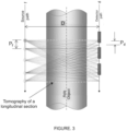
- the collection of two-dimensional data is made possible by moving the radioactive source and the detector along the longitudinal axis of the equipment through rails, and varying the angles of positioning of the source and the detector, measuring the densities of the medium by different paths traveled by the beam within the medium or equipment being analyzed, as shown in figure 2 , as disclosed in document BR 102012024416-0 . Because industrial equipment has a longitudinal axis many times larger than its other dimensions (width, depth or diameter), the movement of the sealed radioactive source and the radiation detector is, in this case, limited in this application to a plane.
- Two-dimensional imaging enables a breakthrough in nondestructive testing technology for industrial equipment, by presenting a number of advantages over the conventional gamma-ray profiling technique:
- the system according to document BR 102012024416-0 allows a data file to be generated, with the necessary information and in an appropriate format for image reconstruction, and generates a tomogram of the analyzed region, with indication of densities presented on a color scale as well as a table of values of the coefficients of mass attenuation ( ⁇ ) or density ( ⁇ ) obtained.
- This state of the art system typically uses only one emission source and a radiation detector moving through a positioning rail installed along the outer surface of the industrial equipment to be evaluated.
- the emission source and detector are mounted on supports that feature shields (collimators) that isolate them from background radiation from the environment. These shields feature windows or channels, which are the places through which the radiation beam comes out and enters predominantly from the radioactive source and into the radiation detector, respectively.
- the brackets can rotate on the plane of the source and detector shafts, allowing the collimation channels to be positioned in various orientations, so that radiation can be sent and measured from different positions.
- the orientation of the windows of both the radioactive source and the radiation detector can be changed to cause a perfect alignment of their collimator channels, shown in Figure 2 .
- the radiation that passes through the object in the direction of source alignment detector is measured, avoiding the reading of the scattered radiation.
- This technology presents the drawback that the displacement of the source and the detector are limited to the place where its respective positioning rail is installed, limiting the plane or evaluation region of the system to the position of these rails.
- the state of the art system needs to know precisely the positioning of the emission source and the detector, and perform a fairly precise alignment between them to obtain accurate measurement results.
- the equipment for adjusting alignment between source and detector, and the electronic control of this equipment is complex, difficult and increases costs of the system shown in this patent document.
- the system according to this prior art only obtains two-dimensional images of the inside of the equipment, making it difficult to diagnose some particularities of operation and the analysis of the inputs inside it.
- an imaging system for industrial equipment using gamma-ray or X-ray profiling techniques and tomographic image reconstruction comprising:
- Said maximum scattering angle can be, for example, less than or equal to 25o.
- the range of energy values of the selected samples is set to E ⁇ TH i ⁇ E M ⁇ E + TH s wherein
- the detection subsystem can comprise a plurality of radiation detectors installed in distinct longitudinal planes on the outer surface of the industrial equipment.
- the emission subsystem and the detection subsystem are preferably installed on the outer surface of the industrial equipment at a source-detector D distance perpendicular to the longitudinal axis of the equipment, and forming a relative ⁇ angle between them, and the source-detector distance D and the relative angle ⁇ are known by the means of processing and imaging and used in the tomographic reconstruction of imagery of the industrial equipment.
- the relative ⁇ angle between the source and the detector for measuring the energy of the radiation passing through the industrial equipment can be less than or equal to 45o.
- the at least one source and the at least one detector are longitudinally displaceable along the industrial equipment, respectively, in source pitches Pf and detector pitches Pd which, according to an embodiment of the invention, can be less than or equal to one tenth of the source-detector D distance.
- Source and detector can each comprise a collimator.
- said maximum scattering angle is less than or equal to 25o.
- the range of energy values of the selected samples is defined as E - TH i ⁇ E M ⁇ E + TH s , wherein
- the step of detecting the energy of the emitted radiation can be performed by a plurality of radiation detectors installed on different longitudinal planes on the outer surface of the industrial equipment, which detect the radiation emitted by at least one radiation source.
- a plurality of radiation detectors installed on different longitudinal planes on the outer surface of the industrial equipment, which detect the radiation emitted by at least one radiation source.
- the generation step of a tomographic reconstruction of imagery of the industrial equipment three-dimensional images can be generated.
- the imaging system for industrial equipment uses gamma-ray or X-ray profiling techniques and tomographic image reconstruction.
- the system according to the invention comprises a radiation emission subsystem 1 and a radiation detection subsystem 2.
- the emission subsystem 1 has at least one radiation source 6 that emits radiation that passes through an industrial equipment to be analyzed by imaging.
- This radiation source may or may not be sealed.
- radiation sources applicable to the system according to invention are radioactive sources emitting gamma radiation of higher energies comprising Caesium-137 or Cobalt-60, not limited to these, which are radioisotopes typically used for the gamma graphing of industrial equipment.
- the radiation detection subsystem 2 comprises at least one radiation detector 7, which detects the radiation emitted by the radiation emission subsystem 1 that went through said industrial equipment, as shown in Figure 1 .
- radiation detectors used in the system according to invention are CsI(TI) or NaI(TI) scintillator detectors, for their higher counting efficiency. They are typically connected to signal amplification and discrimination means, resulting in a typical radiation detection subsystem, which is therefore made up of the following components: scintillator detector, preamplifier, amplifier, pulse discrimination module, high voltage module, power module, timer, counter, communication module, connectors and cables.
- Both radiation source 6 and radiation detector 7 can be coupled to attenuation, collimation and safety means.
- Collimators or shields isolate the source and/or radiation detector from backgrounds from the environment, and from scattered radiation. These shields feature windows or channels, which are the places through which the radiation beam comes out and enters predominantly from the radioactive source and into the radiation detector, respectively.
- detector 7 and source 6 are preferably coupled to supports that can rotate on the plane of the source and detector shafts, allowing collimation channels to be positioned in various orientations, so that radiation can be sent and measured from different positions.
- the system must be adjusted to the invention to electronically adjust and control the orientation of the windows of both the radioactive source and the radiation detector to make a perfect alignment of its collimator channels.
- This increases the complexity of the system as it requires the installation of collimators on rotating supports, and means of control and combined adjustment of the positions of the collimators at the source and in the detector. Therefore, these collimators or shields are not necessary for the operation of the system.
- both the at least one source 6 and the at least one detector 7 are installed directly on the outer surface of the industrial equipment under analysis.
- the detection subsystem comprises a plurality of radiation detectors 7 installed on distinct longitudinal planes on the outer surface of the industrial equipment, as shown in Figure 4 .
- the system will perform readings and imaging of the longitudinal planes represented by the lines that connect the source and the detectors, allowing the formation of three-dimensional images.
- the radiation source 6 then emits an ionizing radiation on the industrial equipment, which crosses and is attenuated by the equipment under study.
- the attenuation sustained by radiation depends on the density ( ⁇ ) or the values of the mass attenuation coefficients ( ⁇ ) of the medium, that is, the equipment and the matter contained within it that is crossed by radiation until it reaches the detector. Attenuation also depends on the size of the path traveled. Using tomographic reconstruction, the distribution of this property within a region under analysis is obtained, with a limited number of measurements.
- the measured radiation attenuation values allow an average longitudinal density profile of the equipment to be obtained, from which tomographic reproduction by image will be generated.
- the function of radiation attenuation can be given as a sequence of attenuations of elements of finite sizes, which results in a product of functions.
- a longitudinal section is reduced to a matrix of "m" rows by “n” columns.
- this matrix m x n
- all measurements of attenuated radiations are obtained at each of the points (m x n) of the matrix.
- Each electromagnetic wave (gamma ray or X-ray) that passes through a certain number of cells in this matrix underwent some attenuation measured by the radiation detector.
- the analytical or iterative resolution which determines the property of each of these elements, is what the tomographic reconstruction of the image is about.
- the radiation emission source and the detector are installed on the outer surface of the industrial equipment at a source-detector Distance D measured perpendicular to the longitudinal axis of the equipment.
- the source or each source 6 and the detector or each detector 7 form a relative ⁇ angle between them, in each position they assume along the longitudinal axis of the equipment.
- Source 6 and radiation detector 7 can be moved along the paths shown as "f" and "d” in figures 1 and 3 . This displacement can be done along guides installed on the outer surface of the equipment, or it can also be done manually. Alternatively, several detectors can be arranged in various longitudinal and/or peripheral positions of the equipment surface, and only the source can be moved. Or several sources can also be installed on the equipment, however the increase in the number of sources and detectors may excessively increase costs of the equipment.
- each source and detector are shifted in certain measures called Pf source pitches and Pd detector pitches.
- the Pf source pitches and the Pd detector pitches are less than or equal to one tenth of the source-detector D distance, to ensure the good quality of the image generated.
- the use of smaller pitches may be desirable or even necessary, when searching for a higher resolution of the tomographic reproduction imagery, reproducing in greater degree of detail the internal densities profile of the equipment. In such cases, the reading and processing time is substantially high. It is therefore ideal to perform an adjustment and a prior configuration of the system, to meet the need of each application.
- the optimal relative angle ⁇ between the source and the detector for measuring the energy of radiation passing through the industrial equipment should be around 45o, to ensure adequate resolution and acceptable quality of the tomographic image obtained.
- the source-detector D distance and the relative angle ⁇ are preferably known and controlled by the system processing and imaging means 5, shown in Figure 1 , mainly in cases where the displacement of the source and detectors is electronically controlled by the processing and imaging means 5.
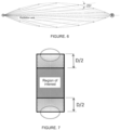
- Figure 7 shows in a schematic way an industrial equipment for analysis according to an embodiment of the invention that uses a maximum relative angle ⁇ between the source and the detector equal to 45o.
- ⁇ between the source and the detector
- other values of relative angles selected depending on the analyzed equipment, and configuration and operation parameters of the system and the process according to the invention can be used.
- the source-detector D distance corresponds to the width of the equipment.
- the central region marked as a region of interest begins and ends at a Distance of D/2 above or below the ends at which measurements begin or have just been made.
- the processing and imaging means 5 have appropriate processors and software to evaluate the radiation detected by the detectors, and to generate tomograms of the analyzed regions.
- the processing and imaging means 5 are therefore connected to the output of the detection subsystem 2 in order to receive the radiation information detected by the radiation detector or the multiple radiation detectors installed in the industrial equipment.
- the processing and imaging means 5 preferably also control the radiation emitted by the radiation source 6, because the knowledge of the radiation emitted is important for the identification of the attenuation sustained after it crosses the industrial equipment.
- the radiation emitted by a source spreads in the middle.
- Some beams of radiation (called non-attenuated photons run a direct path between the source and the detector and are the ones of greatest interest in tomographic reproduction performed by the system of the present invention, because their quantity depends only on attenuations due to the density of the medium crossed, and the length of the path traveled.
- Other beams (called scattered radiation) sustained deviations and reflections along the way, before being detected by the detector. The deviations and reflections sustained interfere in the computation of the detected radiation, so that it ceases to be a direct function of the path traveled and the density of the medium. This scattered radiation is therefore of lesser interest to tomographic reproduction.
- Figure 5 shows a graph relating the amount of radiation samples detected by a detector and the energy of these samples, forming a spectrum of detected energies.
- the E value shown in the graph corresponds to the characteristic energy of the radioactive source.
- the samples around the E value of energy characteristic of the radioactive source usually correspond to the radiation with the lowest scattering and, therefore, better represent the variation of density of the traversed medium.
- One way to use only detected energy samples that have not sustained or undergone only an acceptable degree of scattering is by selecting only the samples in a window or range of values around the E value in the graph.
- the window of values around the E value, as shown in Figure 5 corresponding to the energy range that is to be observed, so that only the radiation samples measured within that window should be taken into account in the evaluation for tomographic reproduction.
- This range of energy values of the samples corresponds to a defined maximum scattering angle of the radiation emitted by the radiation source, which is acceptable for tomographic reproduction.
- the graphic illustration of figure 6 shows an almond profile volume that involves the radiation measured by the detector, radiation that has a maximum scattering angle of 25o, a value used in this embodiment of the system according to the invention. However, you can use other maximum scatter angle values that may vary with the type of source and other system and equipment requirements under analysis.
- the window or range of values is formed around the characteristic energy value of the E source, and between the limits of lower energy variation TH i and superior TH s .
- This window corresponds to the range of energy values of the samples selected for tomographic reproduction.
- the processing and imaging means 5 are configured to select only the samples of measured energy E M that meet the E - TH i ⁇ E M ⁇ E + TH s ratio, while the other samples are discarded.
- the lower energy variation limits TH i and superior TH s therefore represent the energy values of the samples with the maximum scattering angle, for example in this embodiment, 25o.
- the invention also refers to an imaging process for industrial equipment using a system as described herein.
- a radiation is emitted and passes through the industrial equipment to be analyzed.
- the radiation emitted that went through said industrial equipment is detected.
- a selection is made of the detected radiation samples that have an energy value within the range of values corresponding to the maximum scattering angle of the radiation emitted from the radiation source, this angle being preferably less than or equal to 25o.
- the range of energy values of the selected samples is preferably defined by the E - TH i ⁇ E M ⁇ E + TH s ratio described herein above.
- a tomographic reconstruction of industrial equipment imagery is then generated based only on these selected radiation samples.
- the step of detecting the energy of the emitted radiation can be performed by a plurality of radiation detectors 7 installed on different longitudinal planes on the outer surface of the industrial equipment, which detect the radiation emitted by one or more radiation sources 7 of the type described herein.
- the source(s) or the detectors are shifted longitudinally along the industrial equipment, respectively, in source pitches Pf and detector pitches Pd.
- the source pitches Pf and detector pitches Pd are less than or equal to one tenth of the source-detector distance D taken perpendicularly to the longitudinal axis of the equipment. The value of 1/10 of the source-detector distance so far has resulted in a good compromise between the quality of the result and the working time.
- step values can be used to be selected depending on the project.
- the system and method of the present invention therefore dispense with collimation and accurate alignment of the source and detector, since the selection of radiation samples measured within a given energy range already eliminates the reading of scattered and unwanted radiation. This effect resulting from the selection and samples is therefore similar to that of collimation made by collimators or shields.
- the present invention achieves a more accurate selection of detected radiation that is useful for tomographic reproduction, and with a simpler technique, which dispenses components that perform perfect physical alignment between source and detector, as well as electronic control of these components. This reduces the complexity of the equipment required in assembling the system according to the invention, making it simpler, lighter, portable, also reducing its cost.
- the system and the process according to the invention also enable the installation of detectors on different longitudinal planes of the equipment to be analyzed, as shown in Figure 4 , and the simultaneous use of these detectors, which allows three-dimensional imaging to be obtained in a simple way and at low cost.
- the processing and imaging means 5 can manage the positioning, acquisition of data by detectors and the processing of image data, automating communication and sequencing of the sampling steps of the radiation detected.
- the processing and imaging means 5 can perform the following procedures: choice of dimensions of the physical arrangement and the necessary adjustments of the instruments for the measurement of the radiation of interest, test and adjustment of the instruments to obtain an optimal relationship between counting efficiency and accuracy of tomographic reconstructions obtained from the two techniques involved - gamma-ray or X-ray profiling and tomographic reconstruction.
- the processing and imaging means 5 also contain a computer program designed to generate a data file in a format appropriate for the reconstruction of tomograms of the analyzed region with indication of densities presented on a color scale, as well as a table of the values of the mass attenuation coefficients ( ⁇ ) or density coefficients ( ⁇ ) obtained.
- Ct scans can be generated on any plane whether horizontal, vertical or slanted, comprising tomographies of the longitudinal section, in which reconstruction is done directly and not from the interpolation of other tomographies, and cross sections or slanted sections of industrial equipment.
- Tomographic reconstruction methods typically employed include ART (Algebraic Reconstruction Technique), MART (Multiplicative Algebraic Reconstruction Technique) and FBP (Filtered Back Projection).
- the imaging system and process of the present invention can be applied to different types of industrial equipment, including, but not limited to, process columns, risers, fixed and fluidized bed reactors, heat exchangers, separator vessels and pipes, and to different types of industrial equipment internals, including, but not limited to, perforated plates, valved plates, multispout plates, high efficiency plates, random and ordered fillings, collector and redispensing plates, liquid and steam dispensers, mist eliminators, fixed and mobile mixers.
- the present invention can also be applied to different types of industrial processes, including, but not limited to, distillation, separation, adsorption, absorption, refining, purification, extraction, concentration, reaction and catalytic reaction, transport of solids, liquids, gases and fluidized bed, heat exchange and mass.
- the ease of installation of the source and detectors allows the present invention to be applied in different types of industrial processes, comprising distillation, separation, adsorption, absorption, refining, purification, extraction, concentration, reaction and catalytic reaction, transport of liquid solids, gases and fluidized bed, heat exchange and mass.
- path characteristics, the available test time, and the desired level of detail determine the amount and location of the positionings made. In each position, a reading is taken of the radiation that passes through the object under study in the source-detector direction. Specific adjustments in measured pulse height are those which determine the energy of measured ionizing radiation.
Landscapes
- Health & Medical Sciences (AREA)
- General Physics & Mathematics (AREA)
- Life Sciences & Earth Sciences (AREA)
- Physics & Mathematics (AREA)
- Radiology & Medical Imaging (AREA)
- General Health & Medical Sciences (AREA)
- Pulmonology (AREA)
- Nuclear Medicine, Radiotherapy & Molecular Imaging (AREA)
- Chemical & Material Sciences (AREA)
- Analytical Chemistry (AREA)
- Biochemistry (AREA)
- Theoretical Computer Science (AREA)
- Engineering & Computer Science (AREA)
- Immunology (AREA)
- Pathology (AREA)
- High Energy & Nuclear Physics (AREA)
- Molecular Biology (AREA)
- Spectroscopy & Molecular Physics (AREA)
- Analysing Materials By The Use Of Radiation (AREA)
Claims (11)
- Bildgebungssystem für Industrieanlagen, unter Verwendung von Gammastrahlen- oder Röntgenstrahl-Profilierungstechniken und tomographischer Bildrekonstruktion, umfassend:(a) ein Strahlungsemissions-Teilsystem (1) mit mindestens einer Strahlungsquelle (6), die Strahlung emittiert, die durch eine industrielle Anlage verläuft, die durch Bildgebung analysiert werden soll;(b) ein Strahlungsdetektions-Teilsystem (2) mit mindestens einem Strahlungsdetektor (7), der die von dem Strahlungsemissions-Teilsystem (1) emittierte Strahlungsenergie erfasst, die durch die Industrieanlage verlaufen ist;(c) Verarbeitungs- und Bildgebungseinrichtungen (5), die die von dem Strahlungsdetektions-Teilsystem (2) erfassten Strahlungsproben empfangen und auswerten und ein Tomogramm des analysierten Bereichs erzeugen,das System dadurch gekennzeichnet ist, dass Verarbeitungs- und Bildgebungseinrichtungen die Strahlungsproben auswählen, die mit einem Energiewert innerhalb eines Wertebereichs erfasst werden, der einem von Null verschiedenen, maximal definierten Streuwinkel (θ) der von der Strahlungsquelle (6) emittierten Strahlung entspricht, und eine tomographische Rekonstruktion von Bildern der industriellen Ausrüstung basierend auf diesen ausgewählten Strahlungsproben erzeugen,wobei der Bereich von Energiewerten der ausgewählten Proben wie folgt definiert ist
 wobeiEM = gemessene Probenenergie;E = charakteristische Energie der Strahlungsquelle; undTHi = untere Energievariationsgrenze, undTHs = obere Energievariationsgrenze.
 - Bildgebungssystem für Industrieanlagen nach Anspruch 1, dadurch gekennzeichnet, dass der maximale Streuwinkel (θ) kleiner als oder gleich wie 25° ist.
- Bildgebungssystem für Industrieanlagen nach einem der vorherigen Ansprüche, dadurch gekennzeichnet, dass das Erfassungsteilsystem (2) eine Vielzahl von Strahlungsdetektoren (7) umfasst, die an verschiedenen Längsebenen auf der äußeren Oberfläche der Industrieanlage installiert sind.
- Bildgebungssystem für Industrieanlagen nach einem der vorherigen Ansprüche, dadurch gekennzeichnet, dass das Emissionsteilsystem (1) und das Detektionsteilsystem (2) konfiguriert sind, um auf der äußeren Oberfläche der Industrieanlage in einem Quellen-Detektor-Abstand (D) senkrecht zu der Längsachse der Anlage installiert zu werden und einen relativen Winkel (α) dazwischen zu bilden, und dass der Quellen-Detektor-Abstand (D) und der relative Winkel (α) den Verarbeitungs- und Bildgebungseinrichtungen (5) bekannt sind, die bei der tomographischen Rekonstruktion von Industrieanlagenbildern verwendet werden.
- Bildgebungssystem für Industrieanlagen nach Anspruch 3, dadurch gekennzeichnet, dass der relative Winkel (α) zwischen der Quelle (6) und dem Detektor (7) zum Messen der Energie der durch die Industrieanlage verlaufenden Strahlung kleiner als oder gleich wie 45° ist.
- Bildgebungssystem für Industrieanlagen nach einem der vorherigen Ansprüche, dadurch gekennzeichnet, dass die mindestens eine Quelle (6) und der mindestens eine Detektor (7) in Längsrichtung der Industrieanlage in Quellenabständen (Pf) bzw. Detektorabständen (Pd) versetzt sind, wobei die Quellenabstände (Pf) und die Detektorabstände (Pd) kleiner als oder gleich wie ein Zehntel des Quellen-Detektor-Abstands (D) sind.
- Bildgebungsverfahren für Industrieanlagen unter Verwendung eines Systems nach einem der vorherigen Ansprüche, dadurch gekennzeichnet, dass es die folgenden Schritte umfasst:Emittieren von Strahlung, die durch eine industrielle Anlage verläuft, um durch Bildgebung analysiert zu werden;Erfassen der emittierten Strahlung, die durch die industrielle Anlage verläuft;Auswählen von erfassten Strahlungsproben, die einen Energiewert innerhalb eines Wertebereichs aufweisen, der einem von Null verschiedenen, definierten maximalen Streuwinkel (θ) der von der Strahlungsquelle emittierten Strahlung entspricht, undErstellen einer tomografischen Rekonstruktion von Industrieanlagenbildern nur basierend auf diesen ausgewählten Strahlungsproben,wobei der Bereich von Energiewerten der ausgewählten Proben wie folgt definiert ist
 wobeiEM = gemessene Probenenergie;E = charakteristische Energie der Strahlungsquelle; undTHi = untere Energievariationsgrenze, undTHs = obere Energievariationsgrenze.
 - Verfahren nach Anspruch 7, dadurch gekennzeichnet, dass der maximale Streuwinkel (θ), der dem Wertebereich der ausgewählten Proben entspricht, kleiner als oder gleich wie 25° ist.
- Verfahren nach einem der Ansprüche 7 bis 8, dadurch gekennzeichnet, dass der Schritt eines Erfassens der Energie der emittierten Strahlung durch eine Vielzahl von Strahlungsdetektoren (7) ausgeführt wird, die in verschiedenen Längsebenen auf der äußeren Oberfläche der Industrieanlage installiert sind und die die von mindestens einer Strahlungsquelle (6) emittierte Strahlung erfassen.
- Verfahren nach einem der Ansprüche 7 bis 9, dadurch gekennzeichnet, dass es während einer Emission und Strahlungserfassung ein Verschieben der mindestens einen Quelle (6) und des mindestens einen Detektors (7) in Längsrichtung entlang der industriellen Ausrüstung in Quellenabständen (Pf) bzw. Detektorabständen (Pd) umfasst, wobei die Quellenabstände (Pf) und die Detektorabstände (Pd) kleiner als oder gleich wie ein Zehntel des Quellen-Detektor-Abstands (D) senkrecht zu der Längsachse der Anlage sind.
- Verfahren nach einem der Ansprüche 7 bis 10, dadurch gekennzeichnet, dass der Schritt eines Erzeugens einer tomographischen Rekonstruktion von Industrieanlagenbildern ein Erzeugen dreidimensionaler Bilder umfasst.
Applications Claiming Priority (2)
| Application Number | Priority Date | Filing Date | Title |
|---|---|---|---|
| BR102018008275-2A BR102018008275B1 (pt) | 2018-04-24 | 2018-04-24 | Sistema e processo de imageamento de equipamentos industriais |
| PCT/BR2018/050248 WO2019204887A1 (pt) | 2018-04-24 | 2018-07-19 | Sistema e processo de imageamento de equipamentos industriais |
Publications (4)
| Publication Number | Publication Date |
|---|---|
| EP3786622A1 EP3786622A1 (de) | 2021-03-03 |
| EP3786622A4 EP3786622A4 (de) | 2022-01-05 |
| EP3786622B1 true EP3786622B1 (de) | 2024-08-14 |
| EP3786622C0 EP3786622C0 (de) | 2024-08-14 |
Family
ID=68293379
Family Applications (1)
| Application Number | Title | Priority Date | Filing Date |
|---|---|---|---|
| EP18916859.4A Active EP3786622B1 (de) | 2018-04-24 | 2018-07-19 | Abbildungssystem und -verfahren für industrielle ausrüstungen |
Country Status (4)
| Country | Link |
|---|---|
| US (1) | US11442030B2 (de) |
| EP (1) | EP3786622B1 (de) |
| BR (1) | BR102018008275B1 (de) |
| WO (1) | WO2019204887A1 (de) |
Families Citing this family (3)
| Publication number | Priority date | Publication date | Assignee | Title |
|---|---|---|---|---|
| GB201915412D0 (en) * | 2019-10-24 | 2019-12-11 | Johnson Matthey Plc | Scanning system and method for scanning vessels |
| US12416588B2 (en) * | 2021-03-22 | 2025-09-16 | Ecolab Usa Inc. | Separation column inspection using off axis gamma scanning |
| GB202114070D0 (en) * | 2021-10-01 | 2021-11-17 | Johnson Matthey Plc | Scanning system and method for scanning vessels |
Family Cites Families (6)
| Publication number | Priority date | Publication date | Assignee | Title |
|---|---|---|---|---|
| JPS6162847A (ja) * | 1984-09-05 | 1986-03-31 | Toshiba Corp | 産業用断層撮影装置 |
| EP0898704A1 (de) * | 1997-01-24 | 1999-03-03 | Quanta Vision, Inc. | Inspektionsausrüstung mittels kleinwinkeltopographie zur bestimmung der internen struktur und zusammensetzung eines objekt |
| CN101198860A (zh) * | 2005-06-16 | 2008-06-11 | Ⅱ-Ⅵ有限公司 | 能量鉴别散射成像系统 |
| GB2496736B (en) * | 2011-11-02 | 2015-11-11 | Johnson Matthey Plc | Scanning method and apparatus |
| BR102012024416B1 (pt) | 2012-09-26 | 2020-12-08 | Comissão Nacional De Energia Nuclear | sistema de imageamento de equipamentos industriais |
| EP3265789B1 (de) * | 2015-03-06 | 2019-12-25 | GE Sensing & Inspection Technologies GmbH | Bildgebungssystem und -verfahren mit streuungskorrektur |
-
2018
- 2018-04-24 BR BR102018008275-2A patent/BR102018008275B1/pt active IP Right Grant
- 2018-07-19 WO PCT/BR2018/050248 patent/WO2019204887A1/pt not_active Ceased
- 2018-07-19 US US17/050,233 patent/US11442030B2/en active Active
- 2018-07-19 EP EP18916859.4A patent/EP3786622B1/de active Active
Also Published As
| Publication number | Publication date |
|---|---|
| WO2019204887A1 (pt) | 2019-10-31 |
| BR102018008275B1 (pt) | 2023-12-12 |
| US20210080406A1 (en) | 2021-03-18 |
| US11442030B2 (en) | 2022-09-13 |
| EP3786622A1 (de) | 2021-03-03 |
| BR102018008275A2 (pt) | 2019-11-05 |
| EP3786622C0 (de) | 2024-08-14 |
| EP3786622A4 (de) | 2022-01-05 |
Similar Documents
| Publication | Publication Date | Title |
|---|---|---|
| US7881424B2 (en) | Method for calibrating dual-energy CT system and method of image reconstruction | |
| EP3087377B1 (de) | Abtastverfahren | |
| EP3242126A1 (de) | Bildgebungsverfahren mit dualenergiestrahlen und system | |
| CN101672806B (zh) | 一种基于代数重建算法的大视野锥束x射线倾斜扫描三维数字成像方法 | |
| Kumar et al. | Computer assisted gamma and X-ray tomography: applications to multiphase flow systems | |
| EP3786622B1 (de) | Abbildungssystem und -verfahren für industrielle ausrüstungen | |
| De Mesquita et al. | Industrial tomography using three different gamma ray | |
| Haraguchi et al. | Tomographic 2-D gamma scanning for industrial process troubleshooting | |
| CN101718719A (zh) | 一种连续扫描三维锥束工业ct角度增量确定方法 | |
| US7056020B2 (en) | Alignment systems and methods for radiographic imaging systems | |
| CN115980104A (zh) | 多角度扫描编码孔x射线衍射断层成像系统及成像方法 | |
| Bücherl et al. | A Bayesian method for the evaluation of segmented gamma scanning measurements–Description of the principle | |
| Oliveira et al. | Comparison among tomographic reconstruction with limited data | |
| US7286631B2 (en) | Method and apparatus for tomosynthesis image quality control | |
| Kim et al. | Industrial gamma-ray tomographic scan method for large scale industrial plants | |
| Haraguchi et al. | Industrial tomographic gamma scan for demister evaluation | |
| JP4062232B2 (ja) | X線ct装置及びx線ct装置による撮像方法 | |
| Bin et al. | Linear computed tomography of two-phase distribution in a rectangular channel | |
| Soubelet et al. | Computed tomography combined with a material decomposition technique using a compact deuterium-deuterium (DD) fast neutron generator | |
| Scanavini et al. | Computed tomography | |
| BR102012024416B1 (pt) | sistema de imageamento de equipamentos industriais | |
| JPH0726919B2 (ja) | 元素濃度分布測定方法および装置 | |
| Siemens | Computerized tomography | |
| KR20110051839A (ko) | 산업설비 외주면 밀착형 감마선 전산 단층 촬영 장치 및 이를 이용한 전산 단층 촬영 방법 | |
| Dantas | A study of uncertainty evaluation in transmission measurement in gamma ray tomography |
Legal Events
| Date | Code | Title | Description |
|---|---|---|---|
| STAA | Information on the status of an ep patent application or granted ep patent |
Free format text: STATUS: THE INTERNATIONAL PUBLICATION HAS BEEN MADE |
|
| PUAI | Public reference made under article 153(3) epc to a published international application that has entered the european phase |
Free format text: ORIGINAL CODE: 0009012 |
|
| STAA | Information on the status of an ep patent application or granted ep patent |
Free format text: STATUS: REQUEST FOR EXAMINATION WAS MADE |
|
| 17P | Request for examination filed |
Effective date: 20201120 |
|
| AK | Designated contracting states |
Kind code of ref document: A1 Designated state(s): AL AT BE BG CH CY CZ DE DK EE ES FI FR GB GR HR HU IE IS IT LI LT LU LV MC MK MT NL NO PL PT RO RS SE SI SK SM TR |
|
| AX | Request for extension of the european patent |
Extension state: BA ME |
|
| DAV | Request for validation of the european patent (deleted) | ||
| DAX | Request for extension of the european patent (deleted) | ||
| A4 | Supplementary search report drawn up and despatched |
Effective date: 20211206 |
|
| RIC1 | Information provided on ipc code assigned before grant |
Ipc: G01T 1/29 20060101ALI20211130BHEP Ipc: G01N 23/046 20180101AFI20211130BHEP |
|
| GRAP | Despatch of communication of intention to grant a patent |
Free format text: ORIGINAL CODE: EPIDOSNIGR1 |
|
| STAA | Information on the status of an ep patent application or granted ep patent |
Free format text: STATUS: GRANT OF PATENT IS INTENDED |
|
| INTG | Intention to grant announced |
Effective date: 20240306 |
|
| GRAS | Grant fee paid |
Free format text: ORIGINAL CODE: EPIDOSNIGR3 |
|
| GRAA | (expected) grant |
Free format text: ORIGINAL CODE: 0009210 |
|
| STAA | Information on the status of an ep patent application or granted ep patent |
Free format text: STATUS: THE PATENT HAS BEEN GRANTED |
|
| AK | Designated contracting states |
Kind code of ref document: B1 Designated state(s): AL AT BE BG CH CY CZ DE DK EE ES FI FR GB GR HR HU IE IS IT LI LT LU LV MC MK MT NL NO PL PT RO RS SE SI SK SM TR |
|
| REG | Reference to a national code |
Ref country code: GB Ref legal event code: FG4D |
|
| REG | Reference to a national code |
Ref country code: CH Ref legal event code: EP |
|
| REG | Reference to a national code |
Ref country code: DE Ref legal event code: R096 Ref document number: 602018073233 Country of ref document: DE |
|
| REG | Reference to a national code |
Ref country code: IE Ref legal event code: FG4D |
|
| U01 | Request for unitary effect filed |
Effective date: 20240916 |
|
| U07 | Unitary effect registered |
Designated state(s): AT BE BG DE DK EE FI FR IT LT LU LV MT NL PT RO SE SI Effective date: 20241001 |
|
| PG25 | Lapsed in a contracting state [announced via postgrant information from national office to epo] |
Ref country code: NO Free format text: LAPSE BECAUSE OF FAILURE TO SUBMIT A TRANSLATION OF THE DESCRIPTION OR TO PAY THE FEE WITHIN THE PRESCRIBED TIME-LIMIT Effective date: 20241114 |
|
| PG25 | Lapsed in a contracting state [announced via postgrant information from national office to epo] |
Ref country code: GR Free format text: LAPSE BECAUSE OF FAILURE TO SUBMIT A TRANSLATION OF THE DESCRIPTION OR TO PAY THE FEE WITHIN THE PRESCRIBED TIME-LIMIT Effective date: 20241115 Ref country code: PL Free format text: LAPSE BECAUSE OF FAILURE TO SUBMIT A TRANSLATION OF THE DESCRIPTION OR TO PAY THE FEE WITHIN THE PRESCRIBED TIME-LIMIT Effective date: 20240814 |
|
| PG25 | Lapsed in a contracting state [announced via postgrant information from national office to epo] |
Ref country code: IS Free format text: LAPSE BECAUSE OF FAILURE TO SUBMIT A TRANSLATION OF THE DESCRIPTION OR TO PAY THE FEE WITHIN THE PRESCRIBED TIME-LIMIT Effective date: 20241214 |
|
| PG25 | Lapsed in a contracting state [announced via postgrant information from national office to epo] |
Ref country code: HR Free format text: LAPSE BECAUSE OF FAILURE TO SUBMIT A TRANSLATION OF THE DESCRIPTION OR TO PAY THE FEE WITHIN THE PRESCRIBED TIME-LIMIT Effective date: 20240814 |
|
| PG25 | Lapsed in a contracting state [announced via postgrant information from national office to epo] |
Ref country code: ES Free format text: LAPSE BECAUSE OF FAILURE TO SUBMIT A TRANSLATION OF THE DESCRIPTION OR TO PAY THE FEE WITHIN THE PRESCRIBED TIME-LIMIT Effective date: 20240814 Ref country code: RS Free format text: LAPSE BECAUSE OF FAILURE TO SUBMIT A TRANSLATION OF THE DESCRIPTION OR TO PAY THE FEE WITHIN THE PRESCRIBED TIME-LIMIT Effective date: 20241114 |
|
| PG25 | Lapsed in a contracting state [announced via postgrant information from national office to epo] |
Ref country code: RS Free format text: LAPSE BECAUSE OF FAILURE TO SUBMIT A TRANSLATION OF THE DESCRIPTION OR TO PAY THE FEE WITHIN THE PRESCRIBED TIME-LIMIT Effective date: 20241114 Ref country code: PL Free format text: LAPSE BECAUSE OF FAILURE TO SUBMIT A TRANSLATION OF THE DESCRIPTION OR TO PAY THE FEE WITHIN THE PRESCRIBED TIME-LIMIT Effective date: 20240814 Ref country code: NO Free format text: LAPSE BECAUSE OF FAILURE TO SUBMIT A TRANSLATION OF THE DESCRIPTION OR TO PAY THE FEE WITHIN THE PRESCRIBED TIME-LIMIT Effective date: 20241114 Ref country code: IS Free format text: LAPSE BECAUSE OF FAILURE TO SUBMIT A TRANSLATION OF THE DESCRIPTION OR TO PAY THE FEE WITHIN THE PRESCRIBED TIME-LIMIT Effective date: 20241214 Ref country code: HR Free format text: LAPSE BECAUSE OF FAILURE TO SUBMIT A TRANSLATION OF THE DESCRIPTION OR TO PAY THE FEE WITHIN THE PRESCRIBED TIME-LIMIT Effective date: 20240814 Ref country code: GR Free format text: LAPSE BECAUSE OF FAILURE TO SUBMIT A TRANSLATION OF THE DESCRIPTION OR TO PAY THE FEE WITHIN THE PRESCRIBED TIME-LIMIT Effective date: 20241115 Ref country code: ES Free format text: LAPSE BECAUSE OF FAILURE TO SUBMIT A TRANSLATION OF THE DESCRIPTION OR TO PAY THE FEE WITHIN THE PRESCRIBED TIME-LIMIT Effective date: 20240814 |
|
| PG25 | Lapsed in a contracting state [announced via postgrant information from national office to epo] |
Ref country code: SM Free format text: LAPSE BECAUSE OF FAILURE TO SUBMIT A TRANSLATION OF THE DESCRIPTION OR TO PAY THE FEE WITHIN THE PRESCRIBED TIME-LIMIT Effective date: 20240814 |
|
| PG25 | Lapsed in a contracting state [announced via postgrant information from national office to epo] |
Ref country code: CZ Free format text: LAPSE BECAUSE OF FAILURE TO SUBMIT A TRANSLATION OF THE DESCRIPTION OR TO PAY THE FEE WITHIN THE PRESCRIBED TIME-LIMIT Effective date: 20240814 |
|
| PG25 | Lapsed in a contracting state [announced via postgrant information from national office to epo] |
Ref country code: SK Free format text: LAPSE BECAUSE OF FAILURE TO SUBMIT A TRANSLATION OF THE DESCRIPTION OR TO PAY THE FEE WITHIN THE PRESCRIBED TIME-LIMIT Effective date: 20240814 |
|
| PLBE | No opposition filed within time limit |
Free format text: ORIGINAL CODE: 0009261 |
|
| STAA | Information on the status of an ep patent application or granted ep patent |
Free format text: STATUS: NO OPPOSITION FILED WITHIN TIME LIMIT |
|
| 26N | No opposition filed |
Effective date: 20250515 |
|
| U20 | Renewal fee for the european patent with unitary effect paid |
Year of fee payment: 8 Effective date: 20250717 |
|
| PGFP | Annual fee paid to national office [announced via postgrant information from national office to epo] |
Ref country code: GB Payment date: 20250728 Year of fee payment: 8 |
|
| REG | Reference to a national code |
Ref country code: CH Ref legal event code: H13 Free format text: ST27 STATUS EVENT CODE: U-0-0-H10-H13 (AS PROVIDED BY THE NATIONAL OFFICE) Effective date: 20260224 |