EP3786584A1 - Verfahren, vorrichtung und system zur auswahl von sensorsystemen für kartenmerkmalsgenauigkeit und zuverlässigkeitsspezifikationen - Google Patents
Verfahren, vorrichtung und system zur auswahl von sensorsystemen für kartenmerkmalsgenauigkeit und zuverlässigkeitsspezifikationen Download PDFInfo
- Publication number
- EP3786584A1 EP3786584A1 EP20193440.3A EP20193440A EP3786584A1 EP 3786584 A1 EP3786584 A1 EP 3786584A1 EP 20193440 A EP20193440 A EP 20193440A EP 3786584 A1 EP3786584 A1 EP 3786584A1
- Authority
- EP
- European Patent Office
- Prior art keywords
- error
- passes
- location
- data
- survey point
- Prior art date
- Legal status (The legal status is an assumption and is not a legal conclusion. Google has not performed a legal analysis and makes no representation as to the accuracy of the status listed.)
- Pending
Links
Images


Classifications
-
- G—PHYSICS
- G01—MEASURING; TESTING
- G01C—MEASURING DISTANCES, LEVELS OR BEARINGS; SURVEYING; NAVIGATION; GYROSCOPIC INSTRUMENTS; PHOTOGRAMMETRY OR VIDEOGRAMMETRY
- G01C21/00—Navigation; Navigational instruments not provided for in groups G01C1/00 - G01C19/00
- G01C21/38—Electronic maps specially adapted for navigation; Updating thereof
- G01C21/3804—Creation or updating of map data
- G01C21/3833—Creation or updating of map data characterised by the source of data
- G01C21/3848—Data obtained from both position sensors and additional sensors
-
- G—PHYSICS
- G01—MEASURING; TESTING
- G01C—MEASURING DISTANCES, LEVELS OR BEARINGS; SURVEYING; NAVIGATION; GYROSCOPIC INSTRUMENTS; PHOTOGRAMMETRY OR VIDEOGRAMMETRY
- G01C21/00—Navigation; Navigational instruments not provided for in groups G01C1/00 - G01C19/00
- G01C21/26—Navigation; Navigational instruments not provided for in groups G01C1/00 - G01C19/00 specially adapted for navigation in a road network
- G01C21/28—Navigation; Navigational instruments not provided for in groups G01C1/00 - G01C19/00 specially adapted for navigation in a road network with correlation of data from several navigational instruments
- G01C21/30—Map- or contour-matching
- G01C21/32—Structuring or formatting of map data
-
- G—PHYSICS
- G01—MEASURING; TESTING
- G01C—MEASURING DISTANCES, LEVELS OR BEARINGS; SURVEYING; NAVIGATION; GYROSCOPIC INSTRUMENTS; PHOTOGRAMMETRY OR VIDEOGRAMMETRY
- G01C21/00—Navigation; Navigational instruments not provided for in groups G01C1/00 - G01C19/00
- G01C21/38—Electronic maps specially adapted for navigation; Updating thereof
- G01C21/3804—Creation or updating of map data
- G01C21/3833—Creation or updating of map data characterised by the source of data
- G01C21/3837—Data obtained from a single source
-
- G—PHYSICS
- G06—COMPUTING; CALCULATING OR COUNTING
- G06V—IMAGE OR VIDEO RECOGNITION OR UNDERSTANDING
- G06V20/00—Scenes; Scene-specific elements
- G06V20/50—Context or environment of the image
- G06V20/52—Surveillance or monitoring of activities, e.g. for recognising suspicious objects
- G06V20/54—Surveillance or monitoring of activities, e.g. for recognising suspicious objects of traffic, e.g. cars on the road, trains or boats
-
- G—PHYSICS
- G06—COMPUTING; CALCULATING OR COUNTING
- G06V—IMAGE OR VIDEO RECOGNITION OR UNDERSTANDING
- G06V20/00—Scenes; Scene-specific elements
- G06V20/50—Context or environment of the image
- G06V20/56—Context or environment of the image exterior to a vehicle by using sensors mounted on the vehicle
- G06V20/588—Recognition of the road, e.g. of lane markings; Recognition of the vehicle driving pattern in relation to the road
Definitions
- map service providers have relied on data (e.g., imagery) collected from a variety of sources with different views or perspectives (e.g., top-down imagery from satellites, ground-level imagery from surface vehicles, etc.). Map service providers can then, for instance, identify common semantic features (e.g., lane markings, signs, etc.) across the image views for map making, localization, and/or other similar location-based services.
- data e.g., imagery
- Map service providers can then, for instance, identify common semantic features (e.g., lane markings, signs, etc.) across the image views for map making, localization, and/or other similar location-based services.
- mapping and change detection data is becoming increasingly feasible.
- GPS global positioning system
- map service providers face significant technical challenges to automatically select the most appropriate ground-level sensor system before the corresponding data is incorporated into high-resolution digital maps for modern automated applications (e.g., autonomous driving).
- a method comprises selecting at least one survey point that has a known physical location.
- the method also comprises initiating a plurality of passes to capture a plurality of images of the at least one survey point using a sensor system.
- the method further comprises calculating an estimated location of the at least one survey point based on the plurality of images and calculating error data based on the estimated location and the known physical location.
- the method also comprises generating an error curve with respect to a number of the plurality of passes based on the error data for said each pass.
- the method further comprises providing an output indicating a target number of passes to meet an error specification based on the error curve.
- an apparatus comprises at least one processor, and at least one memory including computer program code for one or more computer programs, the at least one memory and the computer program code configured to, with the at least one processor, cause, at least in part, the apparatus to select at least one survey point that has a known physical location.
- the apparatus is also caused to initiate a plurality of passes to capture a plurality of images of the at least one survey point using a sensor system. For each pass of the plurality of passes, the apparatus is further caused to calculate an estimated location of the at least one survey point based on the plurality of images and calculate error data based on the estimated location and the known physical location.
- the apparatus is also caused to generate an error curve with respect to a number of the plurality of passes based on error data for said each pass.
- the apparatus is further caused to provide an output indicating a target number of passes to meet an error specification based on the error curve.
- a non-transitory computer-readable storage medium carrying one or more sequences of one or more instructions which, when executed by one or more processors, cause, at least in part, an apparatus to perform selecting at least one survey point that has a known physical location.
- the apparatus is also caused to initiate a plurality of passes to capture a plurality of images of the at least one survey point using an image-based sensor system.
- the apparatus is further caused to calculate an estimated location of the at least one survey point based on the plurality of images and calculate error data based on the estimated location and the known physical location.
- the apparatus is also caused to generate an error curve with respect to a number of the plurality of passes based on the error data for said each pass.
- the apparatus is further caused to provide an output indicating a target number of passes to meet an error specification based on the error curve.
- an apparatus comprises means for selecting at least one survey point that has a known physical location.
- the apparatus also comprises means for initiating a plurality of passes to capture a plurality of images of the at least one survey point using a sensor system.
- the apparatus further comprises means for calculating an estimated location of the at least one survey point based on the plurality of images and calculating error data based on the estimated location and the known physical location.
- the apparatus also comprises means for generating an error curve with respect to a number of the plurality of passes based on the error data for said each pass.
- the apparatus further comprises means for providing an output indicating a target number of passes to meet an error specification based on the error curve.
- a method comprising facilitating a processing of and/or processing (1) data and/or (2) information and/or (3) at least one signal, the (1) data and/or (2) information and/or (3) at least one signal based, at least in part, on (or derived at least in part from) any one or any combination of methods (or processes) disclosed in this application as relevant to any embodiment of the invention.
- a method comprising facilitating access to at least one interface configured to allow access to at least one service, the at least one service configured to perform any one or any combination of network or service provider methods (or processes) disclosed in this application.
- a method comprising facilitating creating and/or facilitating modifying (1) at least one device user interface element and/or (2) at least one device user interface functionality, the (1) at least one device user interface element and/or (2) at least one device user interface functionality based, at least in part, on data and/or information resulting from one or any combination of methods or processes disclosed in this application as relevant to any embodiment of the invention, and/or at least one signal resulting from one or any combination of methods (or processes) disclosed in this application as relevant to any embodiment of the invention.
- a method comprising creating and/or modifying (1) at least one device user interface element and/or (2) at least one device user interface functionality, the (1) at least one device user interface element and/or (2) at least one device user interface functionality based at least in part on data and/or information resulting from one or any combination of methods (or processes) disclosed in this application as relevant to any embodiment of the invention, and/or at least one signal resulting from one or any combination of methods (or processes) disclosed in this application as relevant to any embodiment of the invention.
- the methods can be accomplished on the service provider side or on the mobile device side or in any shared way between service provider and mobile device with actions being performed on both sides.
- An apparatus comprising means for performing a method of the claims.
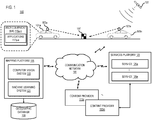
- FIG. 1 is a diagram of a system capable of automatically selecting the most appropriate sensor system for high-definition map feature accuracy and reliability specifications, according to one embodiment.
- automated driving is quickly becoming a reality following advances in machine learning, computer vision, and compute power.
- vehicles 101a-101n also collectively referred to as vehicles 101
- HAD high assisted driving
- semi-autonomous vehicles e.g., autonomous, high assisted driving (HAD), or semi-autonomous vehicles
- Path planning requires knowledge of what to expect beyond a vehicle 101's perceptual horizon, and driving in complicated urban environments with many occluding objects requires a knowledge of what cannot be detected by one or more vehicle sensors 103a-103n (also collectively referred to as vehicle sensors 103)(e.g., a camera sensor, Light Detection and Ranging (LiDAR), etc.).
- vehicle sensors 103a-103n also collectively referred to as vehicle sensors 103
- vehicle sensors 103 e.g., a camera sensor, Light Detection and Ranging (LiDAR), etc.
- map service providers e.g., operating a mapping platform 105
- Map service providers are creating extremely accurate and up-to-date high-resolution maps.
- High-definition digital maps in the form of models of the environment are needed for a wide range of automated applications including transportation, guidance (e.g., farming and/or harvesting), and search and rescue.
- Learning and automating the map creation and update process has therefore been a major research focus in the robotics and artificial intelligence (AI) community for years.
- AI artificial intelligence
- top-down sources like satellite, aerial, and drone images, can be used to precisely determine the location of roads and other features on the Earth (e.g., map features such as lane lines, road boundaries, etc.). These images help create maps at a much larger scale but are more limited to surface features.
- Ground sources like vehicles 101 and/or robots fitted with vehicle sensors 103 may also be exploited to make high definition digital maps. Processing ground sources generally requires more effort and resources to do a larger scale city level collection; however, ground sources can detect map features that are on the Earth's surface as well as traffic lights, signs, etc., which may not be visible from top-down images or sources.
- ground sources can detect map features that are on the Earth's surface as well as traffic lights, signs, etc., which may not be visible from top-down images or sources.
- the advent of less expensive systems e.g., vehicle sensors 103) deployed on vehicles 101 at scale, has enabled crowd-sourced mapping and change detection to become increasingly feasible.
- map service providers face significant technical challenges to automatically select the most appropriate sensor system before the corresponding data is utilized in connection with modern autonomous applications (e.g., autonomous driving).
- the system 100 of FIG. 1 introduces an automatic way to select a sensor system based on its ability to infer the position and the number of observations required to achieve a certain amount of accuracy and reliability of semantic road features (e.g., lane markings, signs, etc.).
- the most appropriate sensor system is the sensor system 103 that has the highest accuracy and reliability relative to the other available sensor systems 103.
- the most appropriate sensor system 103 has the minimalist error tolerance and spread around the error relative to the other available sensor systems 103.
- the system 100 can automatically select the most appropriate sensor system 103 based on respective accuracy and/or reliability percentages as well as the kind of situations where the determined accuracy and reliability specifications are not met by a particular sensor system 103.
- the system 100 obtains a set of survey points 107 (e.g., ground control points) among diverse geographical areas that involve, for instance, tree canopies (e.g., area 201a), open sky areas (e.g., area 201b), urban canyons (e.g., area 201c), natural canyons, etc., as depicted in the example map of FIG. 2 .
- the system 100 can obtain each survey point 107 from one or more vendor archives (e.g., a geographic database 109) via the communication network 111.
- one or more content providers 113a-113m can designate survey points 107 that have precise known location data associated with them (e.g., in the form of ⁇ Latitude, Longitude, Elevation>). These points play a vital role in being able to measure the quality of different sensor systems 103.
- the system 100 determines the relevant accuracy and reliability standards - error tolerance and the spread around the error (e.g., standard deviation) based on the intended automated application (e.g., autonomous driving) for which the selection of a sensor system 103 is being made.
- the system 100 may require a higher degree of accuracy and reliability for ensuring safe automated driving functions, particularly in highly populated areas (e.g., area 201c) or at high speeds and/or the system 100 may require a relatively lower degree of accuracy and reliability for ensuring safe automated guidance functions (e.g., autonomous harvesting), particularly among vast acres of farmland (e.g., area 201b).
- the system 100 selects the sensor systems 103 (e.g., camera sensors, LiDAR sensors, Radar, infrared sensors, thermal sensors, and the like) for which the quality of capture poses needs to be estimated.
- the system 100 selects among the one or more sensor systems 103 for which the system 100 has access to the corresponding data (e.g., stored in or accessible via the geographic database 109).
- the capture pose may include data on sensor position (e.g., location when the corresponding images were captured), sensor pose information (e.g., pointing direction), technical parameters (e.g., field of view, focal length, camera lens, etc.).
- the system 100 prompts one or more vehicles 101 (e.g., autonomous vehicles) with the respective sensor system 103 to drive around, within, etc., one or more areas (e.g., areas 201a, 201b, 201c) to capture each survey point 107.
- vehicles 101 e.g., autonomous vehicles
- areas e.g., areas 201a, 201b, 201c
- the system 100 can also capture a survey point 107 using one or more user equipment (UE) 115a-115n (also collectively referred to herein as UEs 115) associated with a vehicle 101 (e.g., an embedded navigation system), a user or a passenger of a vehicle 101 (e.g., a mobile device, a smartphone, etc.), or a combination thereof using sensing systems like cameras and running perception algorithms on the acquired data (e.g., by executing one or more applications 117a-117n).
- the vehicles 101, the vehicle sensors 103, the UE 115s, and the applications 117a-117n also collectively referred to herein as applications 117 all have connectivity to the mapping platform 105 via the communication network 111.
- the system 100 collects all the captures (e.g., camera images) taken within a certain radius and marks the pixel position of the survey points 107 in each capture if the survey points 107 are visible (e.g., using the computer vision system 119). For example, the system 100 may obtain the captures from the geographic database 109. In one instance, for each capture that has a marked point, the system 100 generates a ray from the camera center to the pixel position in the case of an image sensor 103 and determines the distance of the ray from the 3D position of the survey point 107. In one embodiment, this distance is recorded as an error associated with the capture observation. In the case of LiDAR/Radar sensors, the system 100, for instance, identifies the point position of the survey point 107 in the cloud and measures the distance from it from the surveyed position to determine the error associated with the captured observation.
- the captures e.g., camera images
- the system 100 prompts the one or more vehicles 101 to make multiple passes to capture a survey point 107 multiple times and potentially under multiple conditions.
- the one or more vehicles 101 capture each survey point 107 under different conditions, including multiple and varying speeds to obtain variation in the quality of the GPS signal and GPS/position cumulative drift.
- the system 100 plots the error associated with each capture observation on a curve and determines the mean/standard of deviation with respect to the number of passes. The system 100, in one instance, then correlates the number of passes on the curve with the specified error tolerance and spread (e.g., based on the autonomous application of interest). In one embodiment, the system 100 counts a survey point 107 as void if no number of passes can satisfy the required accuracy/reliability specifications.
- the system 100 for each sensor system 103 (e.g., camera, IMU, LiDAR, Radar, etc.), the system 100 generates a histogram of passes needed to satisfy the relevant accuracy and reliability specifications using all the survey points 107. In one instance, the system 100 determines the mean number of passes and variation across the survey points 107 as well as the number of survey points 107 for which the specifications were not met. In one embodiment, the system 100 then compares the quality of the sensor systems 103 based on the mean number of passes and variation across survey points 107 to select or choose the most appropriate sensor system 103 based on the calculated statistics.
- each sensor system 103 e.g., camera, IMU, LiDAR, Radar, etc.
- FIG. 2 is an example of a map including diverse geographical areas and known survey points, according to one embodiment.
- the map 200 includes diverse geographical areas including, for instance, tree canopies (201a), open sky areas (201b), and urban canyons (201c) and each of the areas 201a-201c includes at least one survey point 107 (e.g., 107a, 107b, and 107c) with a known quality/accuracy (e.g., a physically verified location). Consequently, one or more vehicles 101 can drive around the respective areas to obtain one or more captures (e.g., camera images) of the respective survey points 107 in diverse geographical conditions. It is contemplated that the diverse geographic areas contribute to variations in the quality of the captures which the system 100 can consider when comparing the quality of the sensor system 103.
- FIG. 3 is a diagram of the components of the mapping platform 105, according to one embodiment.
- the mapping platform 105 includes one or more components for automatically selecting the most appropriate sensor system 103 for high-definition map feature accuracy and reliability specifications, according to the various embodiments described herein. It is contemplated that the functions of these components may be combined or performed by other components of equivalent functionality.
- the mapping platform 105 includes a data collection module 301, a communication module 303, a data processing module 305, a graphing module 307, a user interface (UI) module 309, a training module 311, a computer vision system 119, and a machine learning system 121, all with connectivity to the geographic database 109.
- UI user interface
- mapping platform 105 can be implemented in hardware, firmware, software, or a combination thereof. Though depicted as a separate entity in FIG. 1 , it is contemplated that the mapping platform 105 may be implemented as a module of any other component of the system 100. In another embodiment, the mapping platform 105 and/or the modules 301-311 may be implemented as a cloud-based service, local service, native application, or combination thereof. The functions of the mapping platform 105 and/or the modules 301-311 are discussed with respect to FIGs. 4 and 5 .
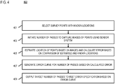
- FIG. 4 is a flowchart of a process for automatically selecting the most appropriate sensor system for high-definition map feature accuracy and reliability specifications, according to one embodiment.
- the mapping platform 105, the computer vision system 119, the machine learning system 121, and/or any of the modules 301-311 may perform one or more portions of the process 400 and may be implemented in, for instance, a chip set including a processor and a memory as shown in FIG. 9 .
- the mapping platform 105, the computer vision system 119, the machine learning system 121, and/or the modules 301-311 can provide means for accomplishing various parts of the process 400, as well as means for accomplishing embodiments of other processes described herein in conjunction with other components of the system 100.
- the process 400 is illustrated and described as a sequence of steps, its contemplated that various embodiments of the process 400 may be performed in any order or combination and need not include all the illustrated steps.
- the data collection module 301 selects at least one survey point that has a known physical location.
- the known physical locations of the one or more survey points 107 may be determined by survey techniques, queried from digital map data (e.g., stored in or accessed via the geographic database 109), and/or any other equivalent technique.
- the known location is based on precise location data (e.g., in the form of ⁇ Latitude, Longitude, Elevation>). Examples of survey points with known physical locations, include, but are not limited to, ground control points which have identifiable physical features whose locations have been precisely surveyed.
- a survey point 107 may refer to any feature that is identifiable by a vehicle sensor 103 (e.g., a camera sensor, LiDAR, Radar, etc.), a UE 115, or a combination thereof such as physical feature on the ground and/or common road furniture (e.g., ground paint, signs, poles, traffic lights, etc.).
- vehicle sensor 103 e.g., a camera sensor, LiDAR, Radar, etc.
- UE 115 e.g., a combination thereof
- survey points 107 refer to a broader category of features than just ground control points.
- the communication module 303 initiates a plurality of passes (e.g., by a vehicle 101) to capture a plurality of images of the at least one survey point 107 using a sensor system 103.
- the communication module 303 may initiate the plurality of passes by transmitting one or more commands or prompts to one or more vehicles 101, one or more drivers of the vehicles 101, or a combination thereof via a UE 115, an application 117, or a combination thereof.
- the plurality of images including the at least one survey point 107 are captured by one or more vehicles 101 (e.g., autonomous vehicles) including one or more vehicle sensors 103 (e.g., GPS, IMU, camera, LiDAR, Radar, etc.) while the one or more vehicles 101 drive or travel in the geographic area including the survey points 107.
- the plurality of images may also be captured by one or more UE 115 (e.g., a mobile device) associated with a vehicle 101 and/or a driver or passenger of the vehicle 101.
- the communication module 303 transmits the one or more commands or prompts in such a way that the plurality of passes are performed under one or more different temporal and/or contextual conditions.
- the different conditions may include passes by the one or more vehicles 101 at multiple and varying vehicle speeds, at different times of the day and/or night, during different weather conditions (e.g., sunny, rainy, foggy, snowing, etc.), or a combination thereof.
- different weather conditions e.g., sunny, rainy, foggy, snowing, etc.
- the data processing module 305 calculates an estimated location of the at least one survey point 107 based on the plurality of images and calculates error data based on the estimated location and the known physical location.
- a vehicle 101 e.g., an autonomous vehicle
- vehicle sensors 103 e.g., camera, LiDAR, etc.
- a geographic area e.g., areas 201a, 201b, 201c
- captures e.g., camera images
- the data processing module 305 can use one or more mathematical principles, for example, to estimate the location of the captured survey point 107. In one instance, the data processing module 305 can also calculate the amount of the error associated with the estimated location and the vehicle sensor 103.
- the data processing module 305 can determine the estimated location of each survey point 107 based on a ray generated from a location of the camera system 103 used to capture each image through a pixel location on an image plane of the plurality of images. In one instance, the data processing module 305 can determine the location of the camera system 103 from image metadata or other data associated with each image (e.g., stored in the geographic database 109). In one embodiment, the data processing module 305 determines the location of the camera system 103 within in a common coordinate system (e.g., a global or a real-world coordinate system indicating ⁇ Latitude, Longitude, Elevation>).
- a common coordinate system e.g., a global or a real-world coordinate system indicating ⁇ Latitude, Longitude, Elevation>.
- the data processing module 305 can use the camera pose data and/or camera technical specifications (e.g., focal length, camera lens, aperture, exposure, etc.), for instance, to locate a physical location of an image plane for each capture (e.g., camera image) within the common coordinate system.
- the image plane refers to the apparent location in three-dimensional space of the image, thereby enabling the data processing module 305 to translate each pixel location (including feature-labeled or detected pixel locations) in an image of each survey point 107 (if visible) into the common coordinate system.
- the data processing module 305 projects a ray (e.g., a line or line segment) from the physical location of the camera system 103 location through the image plane at the marked or labeled pixel location corresponding to the survey point to calculate the estimated location of the captured survey point 107.
- a labeled pixel is a pixel annotated or marked by a labeler (e.g., a human labeler) as corresponding to a feature of interest (e.g., a survey point 107), and a detected pixel is a pixel determined by a computer system (e.g., the computer vision system 119 using machine learning) to be classified as corresponding to a feature of interest.
- the plurality of images can be labeled with one or more survey points 107 that are identifiable in the images. Labeling, for instance, refers to identifying pixels or groups of pixels in the images that correspond to the captured survey points 107, typically but not necessarily by a human.
- the pixels corresponding to a survey point 107 in an image can be detected by automated machine processes.
- the data collection module 301 can detect any map feature that is visible in ground-level imagery (or imagery from any perspectives or views of interest).
- the data collection module 301 can use, for instance, the computer vision system 119 in combination with the machine learning system 121 (e.g., a neural network or equivalent) to recognize the pixels of images that correspond to the visible survey points 107.
- intersection-related features can include but are not limited to intersection-related features, which are generally visible in both top-down and ground-level images. While any kind of visible features can be used according to the embodiments described herein, intersection-related features (e.g., curvilinear geometry intersection features) are particularly suited for automated identification (e.g., via the computer vision system 119) because they exhibit the following properties: (1) have a consistent definition; (2) are uniquely identifiable; (3) have spatial sparsity; and/or (4) are generalizable across different geographic areas (e.g., areas 201a-201c).
- the data processing module 305 calculates the distance between the projected ray and the corresponding survey point 107 wherein the distance represents the error between the estimated location and the known physical location of the survey point 107.
- the data processing module 305 can map the true location of a known survey point 107, using the known physical location of the survey point in the common coordinate system (e.g., the real-world location given by ⁇ Latitude, Longitude, Elevation> or equivalent).
- the data processing module 305 can then compute the minimum perpendicular distance between the true location of the survey point 107 and the corresponding ray. In other words, the minimum perpendicular distance represents the calculated error or error data between the estimated location and the actual location for each pass.
- the data processing module 305 can similarly determine the estimated location of each survey point 107, except in these instances, the point position is within a point cloud generated by the LiDAR or Radar system 103 rather than on an image plane as described above.
- the graphing module 307 generates an error curve with respect to a number of the plurality of passes based on the error data for said each pass.
- each pass of a survey point 107 by a vehicle 101 may generate multiple images of the survey point 107 (e.g., image A, image B, and image C).
- the images A-C may be taken by one or more vehicles 101 at the same location under the same or similar conditions, at different locations under different conditions, or a combination thereof.
- the data processing module 305 can calculate an estimated location of the survey point (e.g., estimated survey point location A, estimated survey point location B, and estimated survey point location C) for each image of each pass (e.g., passes 1-3) as well as the error associated with each estimate and each pass (e.g., errors 1A, 1B, 1C, 2A, 2B, 2C, and 3A, 3B, and 3C).
- the graphing module 207 can plot the various error values on a curve wherein the x-axis represents, for instance, the number of passes by a survey point 107 and the y-axis represents, for instance, the degree of error between the estimated location and the actual location.
- the curve plotted by the graphing module 307 would represent a downward slope left to right such that the degree of error would decrease as a vehicle 101 made more passes of the survey point 107.
- the error data includes a mean, a standard deviation, of a combination thereof of an error between the estimated location and the known location for said each pass.
- the UI module 309 provides an output indicating a target number of passes to meet an error specification based on the error curve.
- the output may be a visual representation in an application 117 of the target passes for each sensor system 103.
- the target number of passes is selected based on a target error tolerance, a target error spread, or a combination thereof.
- the target error tolerance or spread may be based on the autonomous application and/or context under consideration. For example, the digital maps used for autonomous driving in a busy urban center may require a much higher tolerance than the digital maps used for autonomous driving in the countryside. Likewise, the digital maps used for autonomous driving may require a much higher tolerance than the digital maps for autonomous guidance (e.g., farming and/or harvesting).
- the graphing module 307 can generate a histogram of the number of the plurality of passes that meets the error specification using all the survey points (e.g., in a geographic area). In other words, the graphing module 307 can visually represent the frequency of passes (e.g., along the x-axis) relative to the error specification (e.g., along the y-axis).
- the UI module 309 can output the histogram (e.g., via an application 117) so that a user can quickly assess the accuracy or quality of each sensor system 103 and then select the most appropriate sensor system 103 for the high-definition map feature accuracy and reliability specifications. In one instance, the graphing module 307 can also generate a histogram of the mean number of the plurality of passes across one or more of the at least one survey point 107.
- the UI module 309 in connection with the data processing module 305 can provide an output indicating a number of the survey points for which the error specification is not met.
- the data processing module 305 can identify the accuracy and reliability percentages of the various sensor systems 103 as well as the kinds of situations where accuracy and reliability specifications are not met. For example, the crowd-sourced mapping data from a camera sensor system 103 in inclement weather conditions at high speed may not satisfy the accuracy and reliability specifications irrespective of the number of passes made by the camera sensor system 103.
- the data processing module 305 interacts with the training module 311 and the machine learning system 121 to automatically compare or select the sensor system 103 in relation to another sensor system 103 based on the error curve.
- the training module 311 can continuously provide and/or update a machine learning model (e.g., a support vector machine (SVM), a neural network, decision tree, etc.) of the machine learning system 121 during training using, for instance, supervised deep convolution networks or equivalents.
- a machine learning model e.g., a support vector machine (SVM), a neural network, decision tree, etc.
- the training module 311 trains a machine learning model using the various inputs to enable the machine learning system 121 to automatically compare the quality of sensor systems 103 based on accuracy and reliability specifications.
- a machine learning model (e.g., a neural network) is trained to manipulate an input feature set to make a prediction about the feature set or the phenomenon/observation that the feature set represents.
- the training features for the machine learning model include the applicable accuracy and reliability standards, number of passes made in relation to one or more survey points 107, conditions during which the passes were made, sensor systems 103 used in the capturing of the survey points 107, survey points 107 for which the error specification was not met, and the corresponding error curves.
- the machine learning system 121 can consequently predict the accuracy and reliability percentages for the various sensor systems 103 and the kinds of situations where accuracy and reliability specifications will not be met.
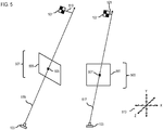
- FIG. 5 is a diagram illustrating an example of rays projected to estimate the location of a captured survey point and to determine the error associated with the capture observation, according to one embodiment.
- images 501 and 503 are processed to estimate the location of the captured survey point 107 having a known physical location (e.g., in the form of ⁇ Latitude, Longitude, Elevation>).
- the images 501 and 503 are derived from passes of the survey point 107 by one or more vehicles 101 (e.g., an autonomous vehicle) with one or more vehicle sensors 103 (e.g., camera, LiDAR, Radar, etc.).
- the images 501 and 503 are captured using a camera sensor 103 and represent all the captures of the survey point 107 within a certain radius.
- the pixel positions 505 and 507 corresponding to the survey point 107 are marked (e.g., by a human) with respect to the images 501 and 503, respectively.
- the mapping platform 105 uses the pose data and/or camera parameters of the camera system 103 to determine the physical location of the image planes 509 and 511 (e.g., corresponding to images 501 and 503, respectively), which represent the location and orientation of the images 501 and 503 with respect to the coordinate system 513.
- the mapping platform 105 for each labeled or detected pixel location 505 and 507 of the images 501 and 503, the mapping platform 105 generates rays 515 and 517 originating from the center of the camera sensor 103 through each of the labeled or detected pixel locations 505 and 507. To determine the accuracy of the estimated survey point locations, the mapping platform 105 can iteratively evaluate the closeness between rays 515 and 517 and the known location of the survey point 107. In one instance, the mapping platform 105 determines the closeness value by computing line segments 519 and 521 between the known location of the survey point 107 and the rays 515 and 517, respectively. As shown, the line segments 517 and 519 are drawn orthogonal to the known location of the survey point 107. In one embodiment, this orthogonality helps ensure that the line segments 519 and 521 are the shortest or minimum distance between the rays 515 and 517 and the known location of the survey point 107.
- the minimum perpendicular distances 519 and 521 between the known location of the survey point 107 and the rays 515 and 517 represent the error associated with the capture observation.
- the minimum perpendicular distances can be aggregated using different measures of central tendency (e.g., mean, median, mode, and so forth).
- a weighting scheme based on an inverse distance of the survey point 107 to the center of each camera sensor 103 could also be used since the confidence in observing a physical point by a camera 103 changes inversely as a function of the distance from the capture.
- the mapping platform 105 can provide an aggregation of error data indicating the quality of the data of the sensor system 103 relative to the number of passes. In one embodiment, the mapping platform 105 can calculate the deviation of the aggregate error data to provide an output (e.g., a histogram) associated with the quality of the sensor system 103. In one embodiment, the mapping platform 105 can count as void if no number of passes can satisfy an error threshold. In one instance, the mapping platform 105 can access the error threshold stored in or accessible via the geographic database 109.
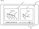
- FIGs. 6A-6C are diagrams of example use interfaces for automatically selecting the most appropriate sensor system based on high-definition map feature accuracy and reliability specifications, according to one embodiment.
- a UI 601 is generated for a UE 115 (e.g., an embedded navigation system) associated with an autonomous vehicle 101 that can enable a user (e.g., a passenger) to access one or more applications 117 (e.g., a navigation application, an analytics application, etc.) while traveling through a large metropolitan city (e.g., San Francisco).
- a UE 115 e.g., an embedded navigation system
- applications 117 e.g., a navigation application, an analytics application, etc.
- the system 100 can notify or alert the user via the UI 601 that a severe storm warning has been issued that will likely affect traffic, path planning, estimated time of arrival, etc.
- the system 100 may receive the notification from a services platform 123 (e.g., an OEM platform) including one or more services 125a-125n (also collectively referred as services 125) (e.g., a weather service), a content provider 113, or a combination thereof.
- a services platform 123 e.g., an OEM platform
- services 125a-125n also collectively referred as services 125
- content provider 113 e.g., a content provider 113
- the system 100 can generate the UI 601 such that it includes an input 603 to enable a user to update the route guidance or path planning based on the most accurate and/or up-to-date mapping data (e.g., crowd-sourced data based on current weather conditions).
- mapping data e.g., crowd-sourced data based on current weather conditions.
- the positional quality of the map features derived from sensor data is heavily dependent on the sensor system 103 (e.g., GPS, IMU, camera, LiDAR, Radar, etc.) used for the data collection and the reliability on the number of such observations/passes.
- the user can interact with the input 603 via one or more physical interactions (e.g., a touch, a tap, a gesture, typing, etc.), one or more voice commands (e.g., "yes,” “update route guidance,” etc.), or a combination thereof.
- one or more physical interactions e.g., a touch, a tap, a gesture, typing, etc.
- voice commands e.g., "yes,” “update route guidance,” etc.
- the system 100 can generate the UI 601 such that it includes a series of inputs (e.g., inputs 605 and 607) that enable a user input various contextual characteristics or values so that the system 100 can filter among the various types of available sensor system data (e.g., via the communication network 111) to reduce the computational resources and time needed for comparing vast amounts of data, as depicted in FIG. 6B .
- the input 605 enables the user to select among various relevant autonomous activities (e.g., driving, guidance, transport, search and rescue, etc.) and the input 607 enables the user to select among various diverse geographic areas (e.g., tree canopy, open sky, urban canyon, natural canyon, etc.).
- the user has selected "driving” and "urban canyon.”
- the inputs 605 and 607 have the same or similar functionality as the inputs 603 in terms of a user's ability to input information.
- the system 100 can automatically detect the applicable autonomous application and/or geographic area when the safety of the autonomous vehicle 101, passengers, and/or other persons or vehicles in the area reaches a certain threshold.
- the system 100 can generate the UI 601 such that it includes one or more outputs (e.g., charts 609 and 611) indicating a target number of passes to satisfy an error specification (e.g., accuracy and reliability standards) based on the error curve of that sensor system 103 as described in the embodiments above.
- the chart 609 represents the target number of passes for a camera sensor system 103 as shown by the error curve 613 and the chart 611 represents the target number of passes for a LiDAR sensor system 103 as shown by the error curve 615.
- the y-axis of each chart 609 and 611 represents the amount of error associated with the capture observation and the x-axis represents the number of passes.
- the system 100 can determine that the number of passes corresponding to an error value equal to or less than one (1) (as shown by the dotted line 617) is required to meet the accuracy and reliability standards or specifications.
- the number of passes corresponding to an error value equal to or less than one (1) is required to meet the accuracy and reliability standards or specifications.
- four (4) passes are required with respect to the camera sensor system 103 and two (2) passes are required with respect the LiDAR sensor system 103.
- the system 100 can also generate the outputs 609 and 611 so that they include visual representations of the number of passes corresponding to the available crowd-sourced data so that the system 100 and/or the user can quickly compare and/or select the most appropriate sensor system 103 based on the calculated statistics.
- the available crowd-sourced camera sensor data includes four pass data (as depicted by the columns 619) whereas the available crowd-sourced LiDAR sensor data only includes one pass data (as depicted by the column 621).
- the system 100 can generate the UI 601 such that it presents the automatically selected sensor system 103 as a recommendation, or a prompt based on the system 100's comparison of the quality of sensor systems 103.
- the system 100 can also generate the UI 601 such that it includes an input 623 to enable the user to accept or reject the recommendation of the system 100.
- the user may want to reject the recommendation of the system 100 and to accept the LiDAR sensor data or to determine whether other any other sensor data is available (e.g., Radar, etc.).
- the system 100 may automatically select the most appropriate sensor system and corresponding data to update the guidance and/or path planning to ensure the safety of the autonomous vehicle 101, the passenger, and/or any nearby persons or vehicles.
- the mapping platform 105 performs the process for automatically selecting the most appropriate sensor system based on high-definition map feature accuracy and reliability specifications as discussed with respect to the various embodiments described herein. For example, with respect to autonomous driving, transportation, guidance, search and rescue, and/or other similar applications, the mapping platform 105 can compare the quality of capture pose data based on the number of passes required to satisfy set error tolerance and spread requirements.
- the machine learning system 121 of the mapping platform 105 includes a neural network or other machine learning system to compare or select sensor systems 103 (e.g., camera, LiDAR, Radar, etc.) for high-definition map feature accuracy and reliability specifications and/or identify kinds of situations where such specifications are not met.
- sensor systems 103 e.g., camera, LiDAR, Radar, etc.
- the output can include one or more recommended sensor systems 103 and corresponding map data for changing and/or updating high definition digital maps.
- the neural network of the machine learning system 121 is a traditional convolutional neural network which consists of multiple layers of collections of one or more neurons (which are configured to process a portion of an input data).
- the machine learning system 121 and/or the computer vision system 119 also have connectivity or access over the communication network 111 to the geographic database 109 which can store the accuracy and reliability standards, error curves, mean/standard of deviation with the numbers of passes, etc. for each sensor system 103.
- the mapping platform 105 has connectivity over the communication network 111 to the services platform 123 (e.g., an OEM platform) that provides the services 125.
- the services 125 may be third party services and include mapping services, navigation services, travel planning services, notification services, social networking services, content (e.g., audio, video, images, etc.) provisioning services, application services, storage services, contextual information determination services, location-based services, information based services (e.g., weather, news, etc.), etc.
- the services 125 use the output of the mapping platform 105 (e.g., recommended sensor system 103) to provide up-to-date services 125 such as navigation, mapping, other location-based services, etc.
- the mapping platform 105 may be a platform with multiple interconnected components.
- the mapping platform 105 may include multiple servers, intelligent networking devices, computing devices, components and corresponding software.
- the mapping platform 105 may be a separate entity of the system 100, a part of the one or more services 125, a part of the services platform 123, or included within a UE 115 and/or a vehicle 101.
- the content providers 113 may provide content or data (e.g., geographic data, parametric representations of mapped features, global or a real-world coordinate system data indicating ⁇ Latitude, Longitude, Elevation> for one or more survey points, 107 etc.) to the vehicles 101, the mapping platform 105, geographic database 109, the UEs 115, the applications 117, the services platform 123, and/or the services 125.
- the content provided may be any type of content, such as map content, survey data, textual content, audio content, video content, image content, etc.
- the content providers 113 may provide content that may aid in the detecting and locating of survey points 107, road furniture (e.g., ground paint, signs, poles, traffic lights, etc.), and/or other relevant features.
- the content providers 113 may also store content associated with the vehicles 101, the mapping platform 105, the geographic database 109, the UEs 115, the computer vision system 119, the machine learning system 121, the services platform 123, and/or the services 125.
- the content providers 113 may manage access to a central repository of data, and offer a consistent, standard interface to data, such as a repository of the geographic database 109.
- a UE 115 may execute a software application 117 to capture image data or other observation data of one or more survey points 107 for automatically selecting the most appropriate sensor system 103 according to the embodiments described herein.
- the applications 117 may also be any type of application that is executable on a UE 115 and/or a vehicle 101, such as autonomous driving applications, mapping applications, analytical applications (e.g., visually graphing and/or comparing), location-based service applications, navigation applications, content provisioning services, camera/imaging applications, media player applications, social networking applications, calendar applications, and the like.
- the applications 117 may act as a client for the mapping platform 105 and perform one or more functions associated with automatically selecting a sensor system 103 alone or in combination with the machine learning system 121.
- the UEs 115 are any type of embedded system, mobile terminal, fixed terminal, or portable terminal including a built-in navigation system, a personal navigation device, mobile handset, station, unit, device, multimedia computer, multimedia tablet, Internet node, communicator, desktop computer, laptop computer, notebook computer, netbook computer, tablet computer, personal communication system (PCS) device, personal digital assistants (PDAs), audio/video player, digital camera/camcorder, positioning device, fitness device, television receiver, radio broadcast receiver, electronic book device, game device, or any combination thereof, including the accessories and peripherals of these devices, or any combination thereof. It is also contemplated that a UE 115 can support any type of interface to the user (such as "wearable" circuitry, etc.). In one embodiment, a UE 115 may be associated with a vehicle 101 (e.g., a mobile device) or be a component part of the vehicle 101 (e.g., an embedded navigation system).
- vehicle 101 e.g., a mobile device
- an embedded navigation system e.
- the vehicles 101 are configured with various sensors 103 for generating or collecting images or representations of one or more survey points 107 (e.g., for processing by the mapping platform 105), related geographic data, etc.
- the vehicles 101 are depicted as automobiles, it is contemplated that the vehicles 101 may be any type of vehicle capable of including one or more sensors 103 (e.g., a car, a truck, a motorcycle, a bike, a scooter, etc.).
- the sensed data represents sensor data associated with a geographic location or coordinates at which the sensor data was collected.
- the vehicle sensors 103 may include GPS for gathering location data, IMU data (e.g., for understanding the motion of a vehicle 101 during a capture), LIDAR, Radar, a network detection sensor for detecting wireless signals or receivers for different short-range communications (e.g., Bluetooth, Wi-Fi, Li-Fi, near field communication (NFC) etc.), temporal information sensors, a camera/imaging sensor for gathering image data (e.g., the camera sensors may automatically capture survey points or ground control point imagery, etc. for analysis), an audio recorder for gathering audio data, velocity sensors mounted on steering wheels of the vehicles, switch sensors for determining whether one or more vehicle switches are engaged, and the like.
- the GPS sensors 103 may be used to determine GPS/position cumulative drift of a vehicle 101.
- sensors of the UEs 115 and/or the vehicles 101 may include light sensors, orientation sensors augmented with height sensors and acceleration sensor (e.g., an accelerometer can measure acceleration and can be used to determine orientation of the vehicle), tilt sensors to detect the degree of incline or decline of a vehicle 101 along a path of travel, moisture sensors, pressure sensors, etc.
- sensors about the perimeter of a vehicle 101 may detect the relative distance of a vehicle 101 from a lane or roadway, the presence of other vehicles, pedestrians, traffic lights, potholes and any other objects, or a combination thereof.
- the sensors may detect weather data, traffic information, or a combination thereof.
- a UE 115 and/or a vehicle 101 may include GPS or other satellite-based receivers to obtain geographic coordinates from one or more satellites 127 for determining current location and time. Further, the location of a vehicle 101, a vehicle sensor 103, and/or a UE 115 can be determined by visual odometry, triangulation systems such as A-GPS, Cell of Origin, or other location extrapolation technologies. In yet another embodiment, one or more sensors can determine the status of various control elements of a vehicle 101, such as activation of wipers, use of a brake pedal, use of an acceleration pedal, angle of the steering wheel, activation of hazard lights, activation of head lights, etc.
- the communication network 111 of the system 100 includes one or more networks such as a data network, a wireless network, a telephony network, or any combination thereof.
- the data network may be any local area network (LAN), metropolitan area network (MAN), wide area network (WAN), a public data network (e.g., the Internet), short range wireless network, or any other suitable packet-switched network, such as a commercially owned, proprietary packet-switched network, e.g., a proprietary cable or fiber-optic network, and the like, or any combination thereof.
- the wireless network may be, for example, a cellular network and may employ various technologies including enhanced data rates for global evolution (EDGE), general packet radio service (GPRS), global system for mobile communications (GSM), Internet protocol multimedia subsystem (IMS), universal mobile telecommunications system (UMTS), etc., as well as any other suitable wireless medium, e.g., worldwide interoperability for microwave access (WiMAX), Long Term Evolution (LTE) networks, code division multiple access (CDMA), wideband code division multiple access (WCDMA), wireless fidelity (Wi-Fi), wireless LAN (WLAN), Bluetooth®, Internet Protocol (IP) data casting, satellite, mobile ad-hoc network (MANET), and the like, or any combination thereof.
- EDGE enhanced data rates for global evolution
- GPRS general packet radio service
- GSM global system for mobile communications
- IMS Internet protocol multimedia subsystem
- UMTS universal mobile telecommunications system
- WiMAX worldwide interoperability for microwave access
- LTE Long Term Evolution
- CDMA code division
- a protocol includes a set of rules defining how the network nodes within the communication network 111 interact with each other based on information sent over the communication links.
- the protocols are effective at different layers of operation within each node, from generating and receiving physical signals of various types, to selecting a link for transferring those signals, to the format of information indicated by those signals, to identifying which software application executing on a computer system sends or receives the information.
- the conceptually different layers of protocols for exchanging information over a network are described in the Open Systems Interconnection (OSI) Reference Model.
- Each packet typically comprises (1) header information associated with a particular protocol, and (2) payload information that follows the header information and contains information that may be processed independently of that particular protocol.
- the packet includes (3) trailer information following the payload and indicating the end of the payload information.
- the header includes information such as the source of the packet, its destination, the length of the payload, and other properties used by the protocol.
- the data in the payload for the particular protocol includes a header and payload for a different protocol associated with a different, higher layer of the OSI Reference Model.
- the header for a particular protocol typically indicates a type for the next protocol contained in its payload.
- the higher layer protocol is said to be encapsulated in the lower layer protocol.
- the headers included in a packet traversing multiple heterogeneous networks, such as the Internet typically include a physical (layer 1) header, a data-link (layer 2) header, an internetwork (layer 3) header and a transport (layer 4) header, and various application (layer 5, layer 6 and layer 7) headers as defined by the OSI Reference Model.
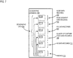
- FIG. 7 is a diagram of a geographic database, according to one embodiment.
- the geographic database 109 includes geographic data 701 used for (or configured to be compiled to be used for) mapping and/or navigation-related services, such as for video odometry based on the captured features (e.g., survey points 107).
- the geographic database 109 includes high resolution or high definition (HD) mapping data that provide centimeter-level or better accuracy of map features.
- the geographic database 109 can be based on LiDAR or equivalent technology to collect billions of 3D points and model road surfaces and other map features down to the number lanes and their widths.
- the HD mapping data (e.g., HD data records 711) capture and store details such as the slope and curvature of the road, lane markings, roadside objects such as signposts, including what the signage denotes.
- the HD mapping data enable highly automated vehicles (e.g., vehicles 101) to precisely localize themselves on the road.
- geographic features are represented using polygons (e.g., two-dimensional features) or polygon extrusions (e.g., three-dimensional features).
- polygons e.g., two-dimensional features
- polygon extrusions e.g., three-dimensional features
- the edges of the polygons correspond to the boundaries or edges of the respective geographic feature.
- a two-dimensional polygon can be used to represent a footprint of the building
- a three-dimensional polygon extrusion can be used to represent the three-dimensional surfaces of the building.
- the following terminology applies to the representation of geographic features in the geographic database 109.
- Node A point that terminates a link.
- Line segment A straight line connecting two points.
- Link (or “edge”) - A contiguous, non-branching string of one or more line segments terminating in a node at each end.
- Shape point A point along a link between two nodes (e.g., used to alter a shape of the link without defining new nodes).
- Oriented link A link that has a starting node (referred to as the “reference node”) and an ending node (referred to as the “non reference node”).
- Simple polygon An interior area of an outer boundary formed by a string of oriented links that begins and ends in one node. In one embodiment, a simple polygon does not cross itself.
- Polygon An area bounded by an outer boundary and none or at least one interior boundary (e.g., a hole or island).
- a polygon is constructed from one outer simple polygon and none or at least one inner simple polygon.
- a polygon is simple if it just consists of one simple polygon, or complex if it has at least one inner simple polygon.
- the geographic database 109 follows certain conventions. For example, links do not cross themselves and do not cross each other except at a node. Also, there are no duplicated shape points, nodes, or links. Two links that connect each other have a common node.
- overlapping geographic features are represented by overlapping polygons. When polygons overlap, the boundary of one polygon crosses the boundary of the other polygon.
- the location at which the boundary of one polygon intersects they boundary of another polygon is represented by a node.
- a node may be used to represent other locations along the boundary of a polygon than a location at which the boundary of the polygon intersects the boundary of another polygon.
- a shape point is not used to represent a point at which the boundary of a polygon intersects the boundary of another polygon.
- the geographic database 109 includes node data records 703, road segment or link data records 705, POI data records 707, quality of capture pose data records 709, HD mapping data records 711, and indexes 713, for example. More, fewer or different data records can be provided. In one embodiment, additional data records (not shown) can include cartographic ("carto") data records, routing data, and maneuver data. In one embodiment, the indexes 713 may improve the speed of data retrieval operations in the geographic database 109. In one embodiment, the indexes 713 may be used to quickly locate data without having to search every row in the geographic database 109 every time it is accessed. For example, in one embodiment, the indexes 713 can be a spatial index of the polygon points associated with stored feature polygons.
- the road segment data records 705 are links or segments representing roads, streets, or paths, as can be used in the calculated route or recorded route information for determination of one or more personalized routes.
- the node data records 703 are end points corresponding to the respective links or segments of the road segment data records 705.
- the road link data records 705 and the node data records 703 represent a road network, such as used by vehicles (e.g., vehicles 1101), cars, and/or other entities.
- the geographic database 109 can contain path segment and node data records or other data that represent pedestrian paths or areas in addition to or instead of the vehicle road record data, for example.
- the road/link segments and nodes can be associated with attributes, such as functional class, a road elevation, a speed category, a presence or absence of road features, geographic coordinates, street names, address ranges, speed limits, turn restrictions at intersections, and other navigation related attributes, as well as POIs, such as gasoline stations, hotels, restaurants, museums, stadiums, offices, automobile dealerships, auto repair shops, buildings, stores, parks, etc.
- the geographic database 109 can include data about the POIs and their respective locations in the POI data records 707.
- the geographic database 109 can also include data about places, such as cities, towns, or other communities, and other geographic features, such as bodies of water, mountain ranges, etc. Such place or feature data can be part of the POI data records 707 or can be associated with POIs or POI data records 707 (such as a data point used for displaying or representing a position of a city).
- the geographic database 109 can also include quality of capture pose data records 709 for storing the known quality/accuracy/location of survey points 107, accuracy and reliability standards or specifications (e.g., for various autonomous applications), pixel positions of the survey points 107 in all previously obtained captures within a certain radius, error associated with the capture observations, error curves, mean/standard of deviation with the number of passes, histograms, percentages, and/or types of situations where accuracy and reliability specifications are not met for automatically selecting a sensor system 103 covering an area of interest.
- accuracy and reliability standards or specifications e.g., for various autonomous applications
- the quality of capture pose data records 709 can be associated with one or more of the node records 703, road segment records 705, and/or POI data records 707 to support localization or visual odometry based on the features (e.g., survey points and/or ground control points) stored therein and the corresponding estimated quality of the features.
- the quality of capture pose data records 709 can also be associated with or used to classify the characteristics or metadata of the corresponding records 703, 705, and/or 707.
- the HD mapping data records 711 model road surfaces and other map features to centimeter-level or better accuracy.
- the HD mapping data records 711 also include lane models that provide the precise lane geometry with lane boundaries, as well as rich attributes of the lane models. These rich attributes include, but are not limited to, lane traversal information, lane types, lane marking types, lane level speed limit information, and/or the like.
- the HD mapping data records 711 are divided into spatial partitions of varying sizes to provide HD mapping data to vehicles 125 (e.g., autonomous vehicles) and other end user devices (e.g., a UE 115) with near real-time speed without overloading the available resources of the vehicles 101 and/or the UEs 115 (e.g., computational, memory, bandwidth, etc. resources).
- vehicles 125 e.g., autonomous vehicles
- other end user devices e.g., a UE 115
- near real-time speed without overloading the available resources of the vehicles 101 and/or the UEs 115 (e.g., computational, memory, bandwidth, etc. resources).
- the HD mapping data records 711 are created from high-resolution 3D mesh or point-cloud data generated, for instance, from LiDAR-equipped vehicles (e.g., one or more vehicles 101).
- the 3D mesh or point-cloud data are processed to create 3D representations of a street or geographic environment at centimeter-level accuracy for storage in the HD mapping data records 711.
- the HD mapping data records 711 also include real-time sensor data collected from probe vehicles in the field (e.g., one or more vehicles 101).
- the real-time sensor data for instance, integrates real-time traffic information, weather, and road conditions (e.g., potholes, road friction, road wear, etc.) with highly detailed 3D representations of street and geographic features to provide precise real-time also at centimeter-level accuracy.
- Other sensor data can include vehicle telemetry or operational data such as windshield wiper activation state, braking state, steering angle, accelerator position, and/or the like.
- the geographic database 109 can be maintained by a content provider 113 in association with the services platform 123 (e.g., a map developer).
- the map developer can collect geographic data to generate and enhance the geographic database 109.
- the map developer can employ field personnel to travel by vehicle (e.g., a vehicle 101 and/or a UE 115) along roads throughout a geographic area of interest to observe features and/or record information about them, for example.
- remote sensing such as aerial or satellite photography (e.g., from the satellites 127), can be used.
- the geographic database 109 can be a master geographic database stored in a format that facilitates updating, maintenance, and development.
- the master geographic database or data in the master geographic database can be in an Oracle spatial format or other spatial format, such as for development or production purposes.
- the Oracle spatial format or development/production database can be compiled into a delivery format, such as a geographic data files (GDF) format.
- GDF geographic data files
- the data in the production and/or delivery formats can be compiled or further compiled to form geographic database products or databases, which can be used in end user navigation devices or systems.
- geographic data is compiled (such as into a platform specification format (PSF) format) to organize and/or configure the data for performing navigation-related functions and/or services, such as route calculation, route guidance, map display, speed calculation, distance and travel time functions, and other functions, by a navigation device, such as by a vehicle 101 or a UE 115, for example.
- the navigation-related functions can correspond to vehicle navigation, pedestrian navigation, or other types of navigation.
- the compilation to produce the end user databases can be performed by a party or entity separate from the map developer.
- a customer of the map developer such as a navigation device developer or other end user device developer, can perform compilation on a received geographic database in a delivery format to produce one or more compiled navigation databases.
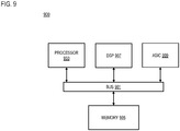
- the processes described herein for automatically selecting the most appropriate sensor system for high-definition map feature accuracy and reliability specifications may be advantageously implemented via software, hardware (e.g., general processor, Digital Signal Processing (DSP) chip, an Application Specific Integrated Circuit (ASIC), Field Programmable Gate Arrays (FPGAs), etc.), firmware or a combination thereof.
- DSP Digital Signal Processing
- ASIC Application Specific Integrated Circuit
- FPGAs Field Programmable Gate Arrays
- FIG. 8 illustrates a computer system 800 upon which an embodiment of the invention may be implemented.
- Computer system 800 is programmed (e.g., via computer program code or instructions) to automatically select the most appropriate sensor system for high-definition map feature accuracy and reliability specifications as described herein and includes a communication mechanism such as a bus 810 for passing information between other internal and external components of the computer system 800.
- Information also called data
- Information is represented as a physical expression of a measurable phenomenon, typically electric voltages, but including, in other embodiments, such phenomena as magnetic, electromagnetic, pressure, chemical, biological, molecular, atomic, sub-atomic and quantum interactions. For example, north and south magnetic fields, or a zero and non-zero electric voltage, represent two states (0, 1) of a binary digit (bit).
- a superposition of multiple simultaneous quantum states before measurement represents a quantum bit (qubit).
- a sequence of one or more digits constitutes digital data that is used to represent a number or code for a character.
- information called analog data is represented by a near continuum of measurable values within a particular range.
- a bus 810 includes one or more parallel conductors of information so that information is transferred quickly among devices coupled to the bus 810.
- One or more processors 802 for processing information are coupled with the bus 810.
- a processor 802 performs a set of operations on information as specified by computer program code related to automatically selecting the most appropriate sensor system for high-definition feature accuracy and reliability specifications.
- the computer program code is a set of instructions or statements providing instructions for the operation of the processor and/or the computer system to perform specified functions.
- the code for example, may be written in a computer programming language that is compiled into a native instruction set of the processor. The code may also be written directly using the native instruction set (e.g., machine language).
- the set of operations include bringing information in from the bus 810 and placing information on the bus 810.
- the set of operations also typically include comparing two or more units of information, shifting positions of units of information, and combining two or more units of information, such as by addition or multiplication or logical operations like OR, exclusive OR (XOR), and AND.
- Each operation of the set of operations that can be performed by the processor is represented to the processor by information called instructions, such as an operation code of one or more digits.
- a sequence of operations to be executed by the processor 802, such as a sequence of operation codes, constitute processor instructions, also called computer system instructions or, simply, computer instructions.
- Processors may be implemented as mechanical, electrical, magnetic, optical, chemical or quantum components, among others, alone or in combination.
- Computer system 800 also includes a memory 804 coupled to bus 810.
- the memory 804 such as a random access memory (RAM) or other dynamic storage device, stores information including processor instructions for automatically selecting the most appropriate sensor system for high-definition feature accuracy and reliability specifications. Dynamic memory allows information stored therein to be changed by the computer system 800. RAM allows a unit of information stored at a location called a memory address to be stored and retrieved independently of information at neighboring addresses.
- the memory 804 is also used by the processor 802 to store temporary values during execution of processor instructions.
- the computer system 800 also includes a read only memory (ROM) 806 or other static storage device coupled to the bus 810 for storing static information, including instructions, that is not changed by the computer system 800.
- ROM read only memory
- Non-volatile (persistent) storage device 808 such as a magnetic disk, optical disk or flash card, for storing information, including instructions, that persists even when the computer system 800 is turned off or otherwise loses power.
- Information including instructions for automatically selecting the most appropriate sensor system for high-definition feature accuracy and reliability specifications, is provided to the bus 810 for use by the processor from an external input device 812, such as a keyboard containing alphanumeric keys operated by a human user, or a sensor.
- an external input device 812 such as a keyboard containing alphanumeric keys operated by a human user, or a sensor.
- a sensor detects conditions in its vicinity and transforms those detections into physical expression compatible with the measurable phenomenon used to represent information in computer system 800.
- Other external devices coupled to bus 810 used primarily for interacting with humans, include a display device 814, such as a cathode ray tube (CRT) or a liquid crystal display (LCD), or plasma screen or printer for presenting text or images, and a pointing device 816, such as a mouse or a trackball or cursor direction keys, or motion sensor, for controlling a position of a small cursor image presented on the display 814 and issuing commands associated with graphical elements presented on the display 814.
- a display device 814 such as a cathode ray tube (CRT) or a liquid crystal display (LCD), or plasma screen or printer for presenting text or images
- a pointing device 816 such as a mouse or a trackball or cursor direction keys, or motion sensor, for controlling a position of a small cursor image presented on the display 814 and issuing commands associated with graphical elements presented on the display 814.
- a display device 814 such as a cathode ray tube (CRT
- special purpose hardware such as an application specific integrated circuit (ASIC) 820, is coupled to bus 810.
- the special purpose hardware is configured to perform operations not performed by processor 802 quickly enough for special purposes.
- application specific ICs include graphics accelerator cards for generating images for display 814, cryptographic boards for encrypting and decrypting messages sent over a network, speech recognition, and interfaces to special external devices, such as robotic arms and medical scanning equipment that repeatedly perform some complex sequence of operations that are more efficiently implemented in hardware.
- Computer system 800 also includes one or more instances of a communications interface 870 coupled to bus 810.
- Communication interface 870 provides a one-way or two-way communication coupling to a variety of external devices that operate with their own processors, such as printers, scanners and external disks.
- the coupling is with a network link 878 that is connected to a local network 880 to which a variety of external devices with their own processors are connected.
- communication interface 870 may be a parallel port or a serial port or a universal serial bus (USB) port on a personal computer.
- USB universal serial bus
- communications interface 870 is an integrated services digital network (ISDN) card or a digital subscriber line (DSL) card or a telephone modem that provides an information communication connection to a corresponding type of telephone line.
- ISDN integrated services digital network
- DSL digital subscriber line
- a communication interface 870 is a cable modem that converts signals on bus 810 into signals for a communication connection over a coaxial cable or into optical signals for a communication connection over a fiber optic cable.
- communications interface 870 may be a local area network (LAN) card to provide a data communication connection to a compatible LAN, such as Ethernet. Wireless links may also be implemented.
- LAN local area network
- the communications interface 870 sends or receives or both sends and receives electrical, acoustic or electromagnetic signals, including infrared and optical signals, that carry information streams, such as digital data.
- the communications interface 870 includes a radio band electromagnetic transmitter and receiver called a radio transceiver.
- the communications interface 870 enables connection to the communication network 111 for automatically selecting the most appropriate sensor system for high-definition feature accuracy and reliability specifications.
- Non-volatile media include, for example, optical or magnetic disks, such as storage device 808.
- Volatile media include, for example, dynamic memory 804.
- Transmission media include, for example, coaxial cables, copper wire, fiber optic cables, and carrier waves that travel through space without wires or cables, such as acoustic waves and electromagnetic waves, including radio, optical and infrared waves. Signals include man-made transient variations in amplitude, frequency, phase, polarization or other physical properties transmitted through the transmission media.
- Computer-readable media include, for example, a floppy disk, a flexible disk, hard disk, magnetic tape, any other magnetic medium, a CD-ROM, CDRW, DVD, any other optical medium, punch cards, paper tape, optical mark sheets, any other physical medium with patterns of holes or other optically recognizable indicia, a RAM, a PROM, an EPROM, a FLASH-EPROM, any other memory chip or cartridge, a carrier wave, or any other medium from which a computer can read.
- a floppy disk a flexible disk, hard disk, magnetic tape, any other magnetic medium, a CD-ROM, CDRW, DVD, any other optical medium, punch cards, paper tape, optical mark sheets, any other physical medium with patterns of holes or other optically recognizable indicia, a RAM, a PROM, an EPROM, a FLASH-EPROM, any other memory chip or cartridge, a carrier wave, or any other medium from which a computer can read.
- FIG. 9 illustrates a chip set 900 upon which an embodiment of the invention may be implemented.
- Chip set 900 is programmed to automatically select the most appropriate sensor system for high-definition map feature accuracy and reliability specifications as described herein and includes, for instance, the processor and memory components described with respect to FIG. 8 incorporated in one or more physical packages (e.g., chips).
- a physical package includes an arrangement of one or more materials, components, and/or wires on a structural assembly (e.g., a baseboard) to provide one or more characteristics such as physical strength, conservation of size, and/or limitation of electrical interaction. It is contemplated that in certain embodiments the chip set can be implemented in a single chip.
- the chip set 900 includes a communication mechanism such as a bus 901 for passing information among the components of the chip set 900.
- a processor 903 has connectivity to the bus 901 to execute instructions and process information stored in, for example, a memory 905.
- the processor 903 may include one or more processing cores with each core configured to perform independently.
- a multi-core processor enables multiprocessing within a single physical package. Examples of a multi-core processor include two, four, eight, or greater numbers of processing cores.
- the processor 903 may include one or more microprocessors configured in tandem via the bus 901 to enable independent execution of instructions, pipelining, and multithreading.
- the processor 903 may also be accompanied with one or more specialized components to perform certain processing functions and tasks such as one or more digital signal processors (DSP) 907, or one or more application-specific integrated circuits (ASIC) 909.
- DSP digital signal processors
- ASIC application-specific integrated circuits
- a DSP 907 typically is configured to process real-world signals (e.g., sound) in real time independently of the processor 903.
- an ASIC 909 can be configured to performed specialized functions not easily performed by a general purposed processor.
- Other specialized components to aid in performing the inventive functions described herein include one or more field programmable gate arrays (FPGA) (not shown), one or more controllers (not shown), or one or more other special-purpose computer chips.
- FPGA field programmable gate arrays
- the processor 903 and accompanying components have connectivity to the memory 905 via the bus 901.
- the memory 905 includes both dynamic memory (e.g., RAM, magnetic disk, writable optical disk, etc.) and static memory (e.g., ROM, CD-ROM, etc.) for storing executable instructions that when executed perform the inventive steps described herein to automatically select the most appropriate sensor system for high-definition map feature accuracy and reliability specifications.
- the memory 905 also stores the data associated with or generated by the execution of the inventive steps.
- FIG. 10 is a diagram of exemplary components of a mobile terminal (e.g., a vehicle 125, a UE 127, or component thereof) capable of operating in the system of FIG. 1 , according to one embodiment.
- a radio receiver is often defined in terms of front-end and back-end characteristics.
- the front-end of the receiver encompasses all of the Radio Frequency (RF) circuitry whereas the backend encompasses all of the base-band processing circuitry.
- Pertinent internal components of the telephone include a Main Control Unit (MCU) 1003, a Digital Signal Processor (DSP) 1005, and a receiver/transmitter unit including a microphone gain control unit and a speaker gain control unit.
- MCU Main Control Unit
- DSP Digital Signal Processor
- a main display unit 1007 provides a display to the user in support of various applications and mobile station functions that offer automatic contact matching.
- An audio function circuitry 1009 includes a microphone 1011 and microphone amplifier that amplifies the speech signal output from the microphone 1011. The amplified speech signal output from the microphone 1011 is fed to a coder/decoder (CODEC) 1013.
- CDDEC coder/decoder
- a radio section 1015 amplifies power and converts frequency in order to communicate with a base station, which is included in a mobile communication system, via antenna 1017.
- the power amplifier (PA) 1019 and the transmitter/modulation circuitry are operationally responsive to the MCU 1003, with an output from the PA 1019 coupled to the duplexer 1021 or circulator or antenna switch, as known in the art.
- the PA 1019 also couples to a battery interface and power control unit 1020.
- a user of mobile station 1001 speaks into the microphone 1011 and his or her voice along with any detected background noise is converted into an analog voltage.
- the analog voltage is then converted into a digital signal through the Analog to Digital Converter (ADC) 1023.
- ADC Analog to Digital Converter
- the control unit 1003 routes the digital signal into the DSP 1005 for processing therein, such as speech encoding, channel encoding, encrypting, and interleaving.
- the processed voice signals are encoded, by units not separately shown, using a cellular transmission protocol such as global evolution (EDGE), general packet radio service (GPRS), global system for mobile communications (GSM), Internet protocol multimedia subsystem (IMS), universal mobile telecommunications system (UMTS), etc., as well as any other suitable wireless medium, e.g., microwave access (WiMAX), Long Term Evolution (LTE) networks, code division multiple access (CDMA), wireless fidelity (WiFi), satellite, and the like.
- a cellular transmission protocol such as global evolution (EDGE), general packet radio service (GPRS), global system for mobile communications (GSM), Internet protocol multimedia subsystem (IMS), universal mobile telecommunications system (UMTS), etc.
- EDGE global evolution
- GPRS general packet radio service
- GSM global system for mobile communications
- IMS Internet protocol multimedia subsystem
- UMTS universal mobile telecommunications system
- any other suitable wireless medium e.g., microwave access (WiMAX), Long Term Evolution (LTE)
- the encoded signals are then routed to an equalizer 1025 for compensation of any frequency-dependent impairments that occur during transmission though the air such as phase and amplitude distortion.
- the modulator 1027 combines the signal with a RF signal generated in the RF interface 1029.
- the modulator 1027 generates a sine wave by way of frequency or phase modulation.
- an up-converter 1031 combines the sine wave output from the modulator 1027 with another sine wave generated by a synthesizer 1033 to achieve the desired frequency of transmission.
- the signal is then sent through a PA 1019 to increase the signal to an appropriate power level.
- the PA 1019 acts as a variable gain amplifier whose gain is controlled by the DSP 1005 from information received from a network base station.
- the signal is then filtered within the duplexer 1021 and optionally sent to an antenna coupler 1035 to match impedances to provide maximum power transfer. Finally, the signal is transmitted via antenna 1017 to a local base station.
- An automatic gain control (AGC) can be supplied to control the gain of the final stages of the receiver.
- the signals may be forwarded from there to a remote telephone which may be another cellular telephone, other mobile phone or a landline connected to a Public Switched Telephone Network (PSTN), or other telephony networks.
- PSTN Public Switched Telephone Network
- Voice signals transmitted to the mobile station 1001 are received via antenna 1017 and immediately amplified by a low noise amplifier (LNA) 1037.
- LNA low noise amplifier
- a down-converter 1039 lowers the carrier frequency while the demodulator 1041 strips away the RF leaving only a digital bit stream.
- the signal then goes through the equalizer 1025 and is processed by the DSP 1005.
- a Digital to Analog Converter (DAC) 1043 converts the signal and the resulting output is transmitted to the user through the speaker 1045, all under control of a Main Control Unit (MCU) 1003-which can be implemented as a Central Processing Unit (CPU) (not shown).
- MCU Main Control Unit
- CPU Central Processing Unit
- the MCU 1003 receives various signals including input signals from the keyboard 1047.
- the keyboard 1047 and/or the MCU 1003 in combination with other user input components (e.g., the microphone 1011) comprise a user interface circuitry for managing user input.
- the MCU 1003 runs a user interface software to facilitate user control of at least some functions of the mobile station 1001 to automatically select the most appropriate sensor system for high-definition map feature accuracy and reliability specifications.
- the MCU 1003 also delivers a display command and a switch command to the display 1007 and to the speech output switching controller, respectively.
- the MCU 1003 exchanges information with the DSP 1005 and can access an optionally incorporated SIM card 1049 and a memory 1051.
- the MCU 1003 executes various control functions required of the station.
- the DSP 1005 may, depending upon the implementation, perform any of a variety of conventional digital processing functions on the voice signals. Additionally, DSP 1005 determines the background noise level of the local environment from the signals detected by microphone 1011 and sets the gain of microphone 1011 to a level selected to compensate for the natural tendency of the user of the mobile station 1001.
- the CODEC 1013 includes the ADC 1023 and DAC 1043.
- the memory 1051 stores various data including call incoming tone data and is capable of storing other data including music data received via, e.g., the global Internet.
- the software module could reside in RAM memory, flash memory, registers, or any other form of writable computer-readable storage medium known in the art including non-transitory computer-readable storage medium.
- the memory device 1051 may be, but not limited to, a single memory, CD, DVD, ROM, RAM, EEPROM, optical storage, or any other non-volatile or non-transitory storage medium capable of storing digital data.
- An optionally incorporated SIM card 1049 carries, for instance, important information, such as the cellular phone number, the carrier supplying service, subscription details, and security information.
- the SIM card 1049 serves primarily to identify the mobile station 1001 on a radio network.
- the card 1049 also contains a memory for storing a personal telephone number registry, text messages, and user specific mobile station settings.
Landscapes
- Engineering & Computer Science (AREA)
- Remote Sensing (AREA)
- Radar, Positioning & Navigation (AREA)
- Physics & Mathematics (AREA)
- General Physics & Mathematics (AREA)
- Automation & Control Theory (AREA)
- Multimedia (AREA)
- Theoretical Computer Science (AREA)
- Traffic Control Systems (AREA)
- Navigation (AREA)
Applications Claiming Priority (1)
| Application Number | Priority Date | Filing Date | Title |
|---|---|---|---|
| US16/557,413 US11003934B2 (en) | 2019-08-30 | 2019-08-30 | Method, apparatus, and system for selecting sensor systems for map feature accuracy and reliability specifications |
Publications (1)
| Publication Number | Publication Date |
|---|---|
| EP3786584A1 true EP3786584A1 (de) | 2021-03-03 |
Family
ID=72290960
Family Applications (1)
| Application Number | Title | Priority Date | Filing Date |
|---|---|---|---|
| EP20193440.3A Pending EP3786584A1 (de) | 2019-08-30 | 2020-08-28 | Verfahren, vorrichtung und system zur auswahl von sensorsystemen für kartenmerkmalsgenauigkeit und zuverlässigkeitsspezifikationen |
Country Status (2)
| Country | Link |
|---|---|
| US (1) | US11003934B2 (de) |
| EP (1) | EP3786584A1 (de) |
Cited By (1)
| Publication number | Priority date | Publication date | Assignee | Title |
|---|---|---|---|---|
| US11492113B1 (en) * | 2019-04-03 | 2022-11-08 | Alarm.Com Incorporated | Outdoor security camera drone system setup |
Families Citing this family (5)
| Publication number | Priority date | Publication date | Assignee | Title |
|---|---|---|---|---|
| US11250051B2 (en) * | 2019-09-19 | 2022-02-15 | Here Global B.V. | Method, apparatus, and system for predicting a pose error for a sensor system |
| US11488395B2 (en) * | 2019-10-01 | 2022-11-01 | Toyota Research Institute, Inc. | Systems and methods for vehicular navigation |
| CN111681417B (zh) * | 2020-05-14 | 2022-01-25 | 阿波罗智联(北京)科技有限公司 | 交通路口渠化调整方法和装置 |
| US20230063809A1 (en) * | 2021-08-25 | 2023-03-02 | GM Global Technology Operations LLC | Method for improving road topology through sequence estimation and anchor point detetection |
| CN114637698B (zh) * | 2022-05-18 | 2022-09-02 | 深圳市倍思科技有限公司 | 机器人的地图内存分配方法、装置、机器人及存储介质 |
Citations (1)
| Publication number | Priority date | Publication date | Assignee | Title |
|---|---|---|---|---|
| US20170122748A1 (en) * | 2015-10-30 | 2017-05-04 | Faraday&Future Inc. | Methods and apparatus for improved precision street maps using low cost sensors |
Family Cites Families (5)
| Publication number | Priority date | Publication date | Assignee | Title |
|---|---|---|---|---|
| US9221396B1 (en) | 2012-09-27 | 2015-12-29 | Google Inc. | Cross-validating sensors of an autonomous vehicle |
| DE102013206707A1 (de) | 2013-04-15 | 2014-10-16 | Robert Bosch Gmbh | Verfahren zur Überprüfung eines Umfelderfassungssystems eines Fahrzeugs |
| US10269192B2 (en) | 2017-04-07 | 2019-04-23 | Airbiquity Inc. | Technologies for verifying control system operation |
| US10831190B2 (en) | 2017-08-22 | 2020-11-10 | Huawei Technologies Co., Ltd. | System, method, and processor-readable medium for autonomous vehicle reliability assessment |
| US10378899B2 (en) * | 2017-09-11 | 2019-08-13 | Goodrich Corporation | Systems and methods for determining position of an object relative to a vehicle |
-
2019
- 2019-08-30 US US16/557,413 patent/US11003934B2/en active Active
-
2020
- 2020-08-28 EP EP20193440.3A patent/EP3786584A1/de active Pending
Patent Citations (1)
| Publication number | Priority date | Publication date | Assignee | Title |
|---|---|---|---|---|
| US20170122748A1 (en) * | 2015-10-30 | 2017-05-04 | Faraday&Future Inc. | Methods and apparatus for improved precision street maps using low cost sensors |
Non-Patent Citations (1)
| Title |
|---|
| CHRISTOPHER K H WILSON ET AL: "The Potential of Precision Maps in Intelligent Vehicles", 1998 IEEE INTERNATIONAL CONFERENCE ON INTELLIGENT VEHICLES, STUTTGART, GERMANY, 30 October 1998 (1998-10-30), pages 1 - 4, XP002533811 * |
Cited By (1)
| Publication number | Priority date | Publication date | Assignee | Title |
|---|---|---|---|---|
| US11492113B1 (en) * | 2019-04-03 | 2022-11-08 | Alarm.Com Incorporated | Outdoor security camera drone system setup |
Also Published As
| Publication number | Publication date |
|---|---|
| US11003934B2 (en) | 2021-05-11 |
| US20210064902A1 (en) | 2021-03-04 |
Similar Documents
| Publication | Publication Date | Title |
|---|---|---|
| US10331957B2 (en) | Method, apparatus, and system for vanishing point/horizon estimation using lane models | |
| US10373002B2 (en) | Method, apparatus, and system for a parametric representation of lane lines | |
| US11410074B2 (en) | Method, apparatus, and system for providing a location-aware evaluation of a machine learning model | |
| US11501104B2 (en) | Method, apparatus, and system for providing image labeling for cross view alignment | |
| US11003934B2 (en) | Method, apparatus, and system for selecting sensor systems for map feature accuracy and reliability specifications | |
| US11263726B2 (en) | Method, apparatus, and system for task driven approaches to super resolution | |
| US11024054B2 (en) | Method, apparatus, and system for estimating the quality of camera pose data using ground control points of known quality | |
| US10984552B2 (en) | Method, apparatus, and system for recommending ground control points for image correction | |
| US11023747B2 (en) | Method, apparatus, and system for detecting degraded ground paint in an image | |
| US11182607B2 (en) | Method, apparatus, and system for determining a ground control point from image data using machine learning | |
| US11170485B2 (en) | Method, apparatus, and system for automatic quality assessment of cross view feature correspondences using bundle adjustment techniques | |
| EP3644013B1 (de) | Verfahren, vorrichtung und system zur positionskorrektur basierend auf der korrespondenz von merkmalspunkten | |
| US11677930B2 (en) | Method, apparatus, and system for aligning a vehicle-mounted device | |
| US11055862B2 (en) | Method, apparatus, and system for generating feature correspondence between image views | |
| US11107235B1 (en) | Systems and methods for identifying data suitable for mapping | |
| US10949707B2 (en) | Method, apparatus, and system for generating feature correspondence from camera geometry | |
| EP3594852B1 (de) | Verfahren, vorrichtung und system zur konstruktion einer hilfskontur aus liniensegmenten | |
| US11367252B2 (en) | System and method for generating line-of-sight information using imagery | |
| EP3664031A1 (de) | Verfahren und vorrichtung zur bereitstellung von feature-triangulation | |
| US20220299341A1 (en) | Method, apparatus, and system for providing route-identification for unordered line data | |
| US10970597B2 (en) | Method, apparatus, and system for priority ranking of satellite images | |
| US20230298362A1 (en) | Method, apparatus, and system for estimating a lane width |
Legal Events
| Date | Code | Title | Description |
|---|---|---|---|
| PUAI | Public reference made under article 153(3) epc to a published international application that has entered the european phase |
Free format text: ORIGINAL CODE: 0009012 |
|
| STAA | Information on the status of an ep patent application or granted ep patent |
Free format text: STATUS: THE APPLICATION HAS BEEN PUBLISHED |
|
| AK | Designated contracting states |
Kind code of ref document: A1 Designated state(s): AL AT BE BG CH CY CZ DE DK EE ES FI FR GB GR HR HU IE IS IT LI LT LU LV MC MK MT NL NO PL PT RO RS SE SI SK SM TR |
|
| AX | Request for extension of the european patent |
Extension state: BA ME |
|
| STAA | Information on the status of an ep patent application or granted ep patent |
Free format text: STATUS: REQUEST FOR EXAMINATION WAS MADE |
|
| 17P | Request for examination filed |
Effective date: 20210903 |
|
| RBV | Designated contracting states (corrected) |
Designated state(s): AL AT BE BG CH CY CZ DE DK EE ES FI FR GB GR HR HU IE IS IT LI LT LU LV MC MK MT NL NO PL PT RO RS SE SI SK SM TR |
|
| STAA | Information on the status of an ep patent application or granted ep patent |
Free format text: STATUS: EXAMINATION IS IN PROGRESS |
|
| 17Q | First examination report despatched |
Effective date: 20221222 |
|
| P01 | Opt-out of the competence of the unified patent court (upc) registered |
Effective date: 20230516 |