EP3786451A1 - Éolienne - Google Patents
Éolienne Download PDFInfo
- Publication number
- EP3786451A1 EP3786451A1 EP19194141.8A EP19194141A EP3786451A1 EP 3786451 A1 EP3786451 A1 EP 3786451A1 EP 19194141 A EP19194141 A EP 19194141A EP 3786451 A1 EP3786451 A1 EP 3786451A1
- Authority
- EP
- European Patent Office
- Prior art keywords
- housing
- wind turbine
- brush
- generator
- gap
- Prior art date
- Legal status (The legal status is an assumption and is not a legal conclusion. Google has not performed a legal analysis and makes no representation as to the accuracy of the status listed.)
- Pending
Links
Images


Classifications
-
- F—MECHANICAL ENGINEERING; LIGHTING; HEATING; WEAPONS; BLASTING
- F03—MACHINES OR ENGINES FOR LIQUIDS; WIND, SPRING, OR WEIGHT MOTORS; PRODUCING MECHANICAL POWER OR A REACTIVE PROPULSIVE THRUST, NOT OTHERWISE PROVIDED FOR
- F03D—WIND MOTORS
- F03D80/00—Details, components or accessories not provided for in groups F03D1/00 - F03D17/00
- F03D80/30—Lightning protection
-
- F—MECHANICAL ENGINEERING; LIGHTING; HEATING; WEAPONS; BLASTING
- F03—MACHINES OR ENGINES FOR LIQUIDS; WIND, SPRING, OR WEIGHT MOTORS; PRODUCING MECHANICAL POWER OR A REACTIVE PROPULSIVE THRUST, NOT OTHERWISE PROVIDED FOR
- F03D—WIND MOTORS
- F03D13/00—Assembly, mounting or commissioning of wind motors; Arrangements specially adapted for transporting wind motor components
- F03D13/20—Arrangements for mounting or supporting wind motors; Masts or towers for wind motors
-
- F—MECHANICAL ENGINEERING; LIGHTING; HEATING; WEAPONS; BLASTING
- F03—MACHINES OR ENGINES FOR LIQUIDS; WIND, SPRING, OR WEIGHT MOTORS; PRODUCING MECHANICAL POWER OR A REACTIVE PROPULSIVE THRUST, NOT OTHERWISE PROVIDED FOR
- F03D—WIND MOTORS
- F03D15/00—Transmission of mechanical power
- F03D15/20—Gearless transmission, i.e. direct-drive
-
- F—MECHANICAL ENGINEERING; LIGHTING; HEATING; WEAPONS; BLASTING
- F03—MACHINES OR ENGINES FOR LIQUIDS; WIND, SPRING, OR WEIGHT MOTORS; PRODUCING MECHANICAL POWER OR A REACTIVE PROPULSIVE THRUST, NOT OTHERWISE PROVIDED FOR
- F03D—WIND MOTORS
- F03D80/00—Details, components or accessories not provided for in groups F03D1/00 - F03D17/00
- F03D80/80—Arrangement of components within nacelles or towers
- F03D80/82—Arrangement of components within nacelles or towers of electrical components
- F03D80/85—Cabling
-
- F—MECHANICAL ENGINEERING; LIGHTING; HEATING; WEAPONS; BLASTING
- F03—MACHINES OR ENGINES FOR LIQUIDS; WIND, SPRING, OR WEIGHT MOTORS; PRODUCING MECHANICAL POWER OR A REACTIVE PROPULSIVE THRUST, NOT OTHERWISE PROVIDED FOR
- F03D—WIND MOTORS
- F03D9/00—Adaptations of wind motors for special use; Combinations of wind motors with apparatus driven thereby; Wind motors specially adapted for installation in particular locations
- F03D9/20—Wind motors characterised by the driven apparatus
- F03D9/25—Wind motors characterised by the driven apparatus the apparatus being an electrical generator
-
- F—MECHANICAL ENGINEERING; LIGHTING; HEATING; WEAPONS; BLASTING
- F05—INDEXING SCHEMES RELATING TO ENGINES OR PUMPS IN VARIOUS SUBCLASSES OF CLASSES F01-F04
- F05B—INDEXING SCHEME RELATING TO WIND, SPRING, WEIGHT, INERTIA OR LIKE MOTORS, TO MACHINES OR ENGINES FOR LIQUIDS COVERED BY SUBCLASSES F03B, F03D AND F03G
- F05B2220/00—Application
- F05B2220/70—Application in combination with
- F05B2220/706—Application in combination with an electrical generator
- F05B2220/7066—Application in combination with an electrical generator via a direct connection, i.e. a gearless transmission
-
- Y—GENERAL TAGGING OF NEW TECHNOLOGICAL DEVELOPMENTS; GENERAL TAGGING OF CROSS-SECTIONAL TECHNOLOGIES SPANNING OVER SEVERAL SECTIONS OF THE IPC; TECHNICAL SUBJECTS COVERED BY FORMER USPC CROSS-REFERENCE ART COLLECTIONS [XRACs] AND DIGESTS
- Y02—TECHNOLOGIES OR APPLICATIONS FOR MITIGATION OR ADAPTATION AGAINST CLIMATE CHANGE
- Y02E—REDUCTION OF GREENHOUSE GAS [GHG] EMISSIONS, RELATED TO ENERGY GENERATION, TRANSMISSION OR DISTRIBUTION
- Y02E10/00—Energy generation through renewable energy sources
- Y02E10/70—Wind energy
- Y02E10/72—Wind turbines with rotation axis in wind direction
-
- Y—GENERAL TAGGING OF NEW TECHNOLOGICAL DEVELOPMENTS; GENERAL TAGGING OF CROSS-SECTIONAL TECHNOLOGIES SPANNING OVER SEVERAL SECTIONS OF THE IPC; TECHNICAL SUBJECTS COVERED BY FORMER USPC CROSS-REFERENCE ART COLLECTIONS [XRACs] AND DIGESTS
- Y02—TECHNOLOGIES OR APPLICATIONS FOR MITIGATION OR ADAPTATION AGAINST CLIMATE CHANGE
- Y02E—REDUCTION OF GREENHOUSE GAS [GHG] EMISSIONS, RELATED TO ENERGY GENERATION, TRANSMISSION OR DISTRIBUTION
- Y02E10/00—Energy generation through renewable energy sources
- Y02E10/70—Wind energy
- Y02E10/728—Onshore wind turbines
Definitions
- the invention describes a wind turbine, and a method of providing a lightning current path for a wind turbine.
- a wind turbine is generally equipped with a lightning protection system (LPS) that aims to provide a current path to guide lightning current to ground.
- LPS lightning protection system
- each rotor blade usually incorporates a down conductor in its interior. Electrically conductive "attractors" or targets can be provided at one or more points on the blade exterior and connected to the down conductor, in order to attract a lightning strike in a controlled manner.
- the down conductors of the rotor blades lead to the hub. It is then necessary to provide a bridge between the rotating hub and the stationary nacelle so that the lightning current can be guided to a down conductor of the wind turbine tower and then to ground.
- One way of doing this is to use a sliding contact between a rotating down conductor in the hub and a stationary down conductor in the nacelle.
- a wind turbine shall be understood to comprise a generator that is enclosed in a generator housing.
- the generator housing comprises a rotating housing and a stationary housing. It may be assumed that the generator housing is made primarily of a material such as steel and is therefore electrically conductive. It may also be assumed in the following that lightning current from the aerodynamic rotor is led to the rotor housing, for example by electrically connecting the rotor blade down conductors to the body of the generator rotor housing.
- An aerodynamic rotor comprising rotor blades mounted to a hub will cause the rotating component to turn during operation of the generator.
- the rotating housing is separated from the stationary housing by a first gap or "housing gap”.
- the wind turbine further comprises a canopy mounted on a tower, and the canopy includes elements of the LPS for electrical connection to a down conductor of the tower.
- the canopy is separated from the generator housing by a second gap or "canopy gap", here also in order to avoid collision between the outer rotor and the canopy.
- the inventive wind turbine is characterized by a lightning current path that is provided by a plurality of brush assemblies mounted on the generator housing, wherein a brush assembly comprises a brush holder mounted on the stationary housing such that a carbon brush contained in the brush holder extends across the housing gap to make electrical contact with the rotating housing, and an electrical connector extending across the canopy gap to electrically connect the brush holder to the LPS elements of the canopy.
- the brush holder comprises an electrically conductive material such as steel. Since the carbon brush is in electrical contact to the brush holder, and the electrical lead originates in the brush holder, any electrical current entering the carbon brush from the rotating housing will pass through the electrical lead to the LPS elements of the canopy.
- An advantage of the wind turbine according to the invention is that the plurality of brush assemblies provides a reliable lightning current path from the aerodynamic rotor to the LPS elements of the canopy, and from there to ground. With a sufficient number of brush assemblies, even a very high lightning current can be reliably guided through this brush assembly arrangement on its way to ground. The likelihood of damage to components of the wind turbine is therefore favourably reduced or even essentially eliminated. For example, the main bearing can be reliably protected from flashover during a lightning event.
- the inventive method of providing a lightning current path for a wind turbine of the type described above comprises steps of providing a plurality of first brush assemblies, wherein a first brush assembly comprises a brush holder containing a carbon brush, and an elongated electrical connector or lead originating in the brush holder and terminating at an outer end; mounting each brush holder on the stationary housing such that the carbon brush extends across the first gap to make electrical contact with the rotating housing; extending the lead across the second gap and securing its outer end to the canopy so that an electrical connection is made between the lead and an LPS element of the canopy.
- rotating component of the generator is to be understood in the sense that this generator component is realised to turn when the generator is in operation.
- the LPS will of course be equally effective when the generator is not operational, i.e. when the rotor and rotor housing are not actually turning.
- the generator housing shall be understood to comprise two parts, a rotating housing that encloses the generator rotating component, and a stationary housing that encloses a generator stationary component.
- the wind turbine is a direct-drive wind turbine.
- the outer rotor is constructed to act as the generator field, although it is possible that the outer rotor carries the armature.
- a main shaft may extend from a front end (i.e. the drive end or upwind end) of the outer rotor into the interior of the canopy.
- This main shaft may have a large diameter.
- the outer rotor is mounted about the main shaft by means of a main bearing at the front end. Another bearing at the non-drive end of the main shaft may be provided, to support the non-drive end of the outer rotor.
- the wind turbine comprises at least 10 brush assemblies, more preferably at least 20 brush assemblies, most preferably at least 30 brush assemblies mounted in an annular arrangement on the generator housing to provide a lightning current path across the canopy gap to the LPS elements of the canopy.
- the current-carrying capacity of an LPS may be specified in a relevant regulation or standard, for example the International Standard IEC 61400-24 that is published by the International Electrotechnical Commission and that relates to wind turbines.
- a wind turbine may be required to have an LPS that can transport 200 kA lightning current.
- the actual number of brush assemblies may be chosen according to the current-carrying capacity of the carbon brush and the lead.
- the current-carrying capacity of the lead of a brush assembly is at least as large as the current-carrying capacity of its carbon brush.
- the electrical connector or lead is flexible, and may be realised as a ribbon cable or a cable braid, so that it can undergo deformation in the event that the canopy gap is not constant as the outer rotor turns.
- This flexibility ensures that the lead continually bridges the canopy gap, even if the gap width varies or fluctuates owing to the large forces exerted by the aerodynamic rotor on the main shaft.
- the electrical connection between generator housing and canopy LPS is therefore unaffected by any slight movements of the generator housing relative to the canopy.
- Each of these brush assemblies is preferably realised such that its carbon brush continually bridges a housing gap of at least 5 mm, more preferably at least 10 mm, most preferably at least 15 mm.
- each of these brush assemblies is realised such that its flexible lead continually bridges a canopy gap of at least 10 cm, more preferably at least 20 cm, most preferably at least 30 cm.
- the LPS elements of the canopy may be provided as an arrangement of down conductors that are incorporated in the body of the canopy, or mounted onto the interior and/or exterior of the canopy. The LPS elements of the canopy are arranged to guide lightning current to a down conductor arrangement of the tower.
- Lightning current can originate from a strike to the canopy itself and/or from a strike to the aerodynamic rotor, in which case the brush assemblies that bridge the canopy gap provide a path to the lightning current.
- the LPS elements of the canopy are realised as an electrically conductive mesh. In this way, the canopy acts as a Faraday cage and provides effective EMC shielding for components inside the canopy.
- the plurality of brush assemblies bridging the canopy gap with the leads extending between stator housing and canopy also act as a type of Faraday cage, so that the overall Faraday cage effect is created by the combination of brush assemblies at the generator/canopy interface and the conductive mesh of the canopy. Charge will therefore be distributed evenly over the canopy and the generator housing.
- the stator housing is constructed to provide EMC shielding for the stator, which may be assumed to be realised as the generator armature.
- the stator housing may comprise an annular metal plate (realised in one piece or in sections) arranged about the main shaft to effectively close off the generator at its non-drive end.
- the metal plate is dimensioned to leave only a very small housing gap between its outer edge and the rotor housing. This annular plate may serve to guide a cooling airflow over the stator windings, and also serves to provide EMC shielding.
- the brush assemblies are mounted onto this "EMC shielding plate".
- a second brush assembly is provided to offer an additional path to lightning current.
- This second brush assembly is preferably provided at the drive end of the generator.
- the second brush assembly is mounted to a turner ring.
- Such a turner ring may be provided for use during installation of the wind turbine, for example to turn the hub to a specific position in order to mount a rotor blade.
- the turner ring generally has a diameter that is larger that the diameter of the main bearing.
- the turner ring can be realised as a toothed ring that engages with the pinions of a number of motor drive units. Since the purpose of the turner ring is to turn the generator rotor (and the aerodynamic rotor) relative to the stator, there will be a gap between the turner ring and the closest stationary element, for example a stator front plate.
- the second lightning current path is provided by a second brush arrangement comprising at least one brush assembly, preferably a plurality of brush assemblies, to provide an electrical connection between the turner ring and the stationary supporting structure.
- the second brush arrangement acts to equalize charge distribution or electrical potential across the generator and protects the main bearing from flashover.
- a brush assembly that bridges the canopy gap may be referred to as a “canopy gap brush assembly”, a “generator housing brush assembly”, a “first brush assembly” or an “exterior brush assembly”.
- a brush assembly mounted at the turner ring may be referred to as a “turner ring brush assembly”, a “second brush assembly”, or an “interior brush assembly”.
- the annular arrangement of brush assemblies that bridges the canopy gap may be referred to as the "generator housing brush arrangement” or “first brush arrangement”, and the arrangement of brush assemblies at the turner ring may be referred to as the “turner ring brush arrangement” or “second brush arrangement”.
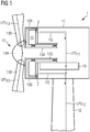
- Fig 1 shows a direct-drive outer-rotor wind turbine of the type described above.
- the wind turbine 1 has a generator 10 that is enclosed in a generator housing 10R, 10S.
- a rotating housing 10R encloses the outer rotor, and a stationary housing 10S encloses the stator.
- the rotating housing 10R is separated from the stationary housing 10R by a housing gap G1 of a few mm.
- the circular shape of the rotor housing 10R may be maintained by an anti-ovalisation ring mounted to the exterior of the rotor housing 10R so that the housing gap G1 may be expected to remain essentially constant.
- the wind turbine 1 further comprises a canopy 11 mounted on a tower 12, and the canopy 11 is separated from the generator housing 10R, 10S by a canopy gap G2, which may be several cm in width.
- the wind turbine has a lightning protection system (LPS) with down conductors arranged in the rotor blades 13 and extending into the hub.
- This lightning protection system LPS 13 of the aerodynamic rotor 13 is electrically connected to the rotor housing 10R.
- the rotor housing 10R may be assumed to be made partially or completely of steel or a similar metal, and is therefore electrically conductive.
- the canopy also includes down conductors of a canopy lightning protection system LPS 11 that are electrically connected to down conductors of a lightning protection system LPS 12 of the tower 12.
- the wind turbine has a first lightning current path P2 that is provided by a plurality of brush assemblies 2 mounted on the stationary housing 10S.
- Each of these brush assemblies 2 comprises a brush holder 20 that is mounted on the stationary housing 10S such that a carbon brush 21 extends across the housing gap G1 to make electrical contact with the rotating housing 10R. This is shown in the enlarged view given by Fig 2 .
- the actual number of brush assemblies 2 is determined according to the current-carrying capacity of the brush assembly type, and on the LPS requirements.
- a circumferential arrangement of 50 or more brush assemblies 2 may be sufficient to ensure that the voltage between rotor and stator does not exceed 2 kV during a 200 kA lightning strike (for the sake of clarity, only two brush assemblies 2 are shown in Fig 1 ).
- the brush assembly 2 has a spring-loaded mechanism, as will be known to the skilled person, which acts to press the carbon brush 21 against the body of the rotor housing 10R. This ensures that the carbon brush 21 will maintain contact with the rotor housing at all times, even as the brush wears down over time, and even if there are slight variations in the width of the housing gap between rotor housing 10R and stator housing 10S due to ovalization of the rotor.
- the spring-loaded mechanism ensures that the brush 21 continually bridges the housing gap G1, even if the gap width varies or fluctuates as the outer rotor turns relative to the stationary housing 10S.
- One stage of the first lightning current path P2 is therefore given by the carbon brush 21 that electrically connects the rotor housing 10R to the stator housing 10S.
- the stator housing 10S may be realised to include an EMC shielding plate at the non-drive end of the generator 10.
- EMC shielding plate at the non-drive end of the generator 10.
- Another known feature of a brush assembly is that the body of the brush assembly is also electrically conductive, and is usually made of steel. Electrical current is therefore passed from the carbon brush to the brush holder.
- the brush holders 20 are mounted in an annular arrangement to the stator housing 10S, so that during a lightning strike or during the build-up to a lightning strike, charge will be able to distribute itself evenly over the EMC shielding plate.
- Each brush assembly 2 also has a lead 22 that extends across the canopy gap G2 to electrically connect the brush holder 20 to the LPS elements of the canopy 11.
- the next stage of the first lightning current path P2 is therefore given by the lead 22 which electrically connects the stator housing 10R to the canopy 11.
- An outer terminal 220 of the lead 22 is connected to a part of the canopy's LPS arrangement.
- the lead 22 is realised as a flexible part, for example a ribbon cable or cable braid, that can adjust to minor alterations in width of the canopy gap G2.
- the length of the lead 22 exceeds the canopy gap width by at least 5%, more preferably by at least 10%, so that the leads can compensate for fluctuations in gap width.
- the canopy 11 is realised to incorporate an LPS system LPS 11 in the form of a conductive mesh 110, and the lead 22 of each brush assembly 2 is connected to a point in this conductive mesh 110.
- Fig 4 shows (schematically) a plurality of brush assemblies 2 mounted on the stator housing 10S as described above to electrically connect the rotor housing 10R to the conductive mesh 110 in the canopy 11.
- the conductive mesh 110 in turn is connected to the LPS system LPS 12 of the tower 21, and from there in the usual manner to ground.
- Fig 5 An alternative arrangement is shown in Fig 5 .
- the canopy 11 is provided with a set of down conductors, one of which is arranged as an annular conductor 112 about the front end of the canopy 11, and all leads 22 of the brush assemblies 2 are connected to this front-end down conductor 112, which in turn is connected to the LPS system LPS 11 of the canopy 11, leading to the LPS system LPS 12 of the tower 21, and from there in the usual manner to ground.
- Fig 6 shows a further embodiment of the inventive wind turbine 1.
- the diagram is a cross-section of the region about the main shaft 15S, 15R with its rotating part 15R and stationary part 15S, indicating the generator's axis of rotation.
- a turner ring 16 is provided for use in the installation of the wind turbine 1.
- the turner ring 16 is structurally a part of the outer rotor, and remains in place after installation, even if it is no longer required.
- Drive units 160 anchored in a stationary front plate 140 are used to turn the ring 16 (and therefore the aerodynamic hub).
- Each drive unit 160 has a pinion 161 that engages with the toothed outer side of the turner ring 16.
- the stationary front plate 140 may be assumed to be electrically connected to a bedframe, which in turn may be assumed to be electrically connected in the usual manner to the LPS system of the wind turbine.
- the diagram shows a second lightning current path P3 that is provided by a plurality of brush assemblies 3 mounted on a stationary front plate 140 that supports the main bearing 14.
- Each of these brush assemblies 3 comprises a brush holder 30 that is mounted on the stationary front plate 140 such that the brush assembly 3 extends across a turner ring gap G3 to make electrical contact with the turner ring 16.
- a spring-loaded mechanism acts to press the carbon brush 31 against the turner ring 16.
- any lightning current reaching the turner ring 16 from the hub 13 will be given a safe path P3 to the stationary front plate 140. Since this front plate 140 is mounted to the bedframe, a safe path to the down conductors of the tower 12 is ensured.
Landscapes
- Engineering & Computer Science (AREA)
- Life Sciences & Earth Sciences (AREA)
- Sustainable Development (AREA)
- Sustainable Energy (AREA)
- Chemical & Material Sciences (AREA)
- Combustion & Propulsion (AREA)
- Mechanical Engineering (AREA)
- General Engineering & Computer Science (AREA)
- Power Engineering (AREA)
- Wind Motors (AREA)
Priority Applications (3)
| Application Number | Priority Date | Filing Date | Title |
|---|---|---|---|
| EP19194141.8A EP3786451A1 (fr) | 2019-08-28 | 2019-08-28 | Éolienne |
| US16/998,438 US11578702B2 (en) | 2019-08-28 | 2020-08-20 | Lightning protection system for wind turbine |
| CN202010887669.2A CN112443463A (zh) | 2019-08-28 | 2020-08-28 | 风力涡轮机 |
Applications Claiming Priority (1)
| Application Number | Priority Date | Filing Date | Title |
|---|---|---|---|
| EP19194141.8A EP3786451A1 (fr) | 2019-08-28 | 2019-08-28 | Éolienne |
Publications (1)
| Publication Number | Publication Date |
|---|---|
| EP3786451A1 true EP3786451A1 (fr) | 2021-03-03 |
Family
ID=67777232
Family Applications (1)
| Application Number | Title | Priority Date | Filing Date |
|---|---|---|---|
| EP19194141.8A Pending EP3786451A1 (fr) | 2019-08-28 | 2019-08-28 | Éolienne |
Country Status (3)
| Country | Link |
|---|---|
| US (1) | US11578702B2 (fr) |
| EP (1) | EP3786451A1 (fr) |
| CN (1) | CN112443463A (fr) |
Families Citing this family (2)
| Publication number | Priority date | Publication date | Assignee | Title |
|---|---|---|---|---|
| EP3916412A1 (fr) * | 2020-05-28 | 2021-12-01 | Ventus Engineering GmbH | Procédé et système pour la surveillance et le diagnostic d'un système de mise à la terre |
| EP4063650A1 (fr) * | 2021-03-24 | 2022-09-28 | Siemens Gamesa Renewable Energy A/S | Réduction de la densité du flux magnétique de la foudre dans les éoliennes |
Citations (5)
| Publication number | Priority date | Publication date | Assignee | Title |
|---|---|---|---|---|
| DE102004010104A1 (de) * | 2004-02-27 | 2005-09-29 | Repower Systems Ag | Blitzschutzeinrichtung für Windenergieanlagen |
| CN201125843Y (zh) * | 2007-12-21 | 2008-10-01 | 广东明阳风电技术有限公司 | 风力发电机组防雷保护系统 |
| WO2011069686A1 (fr) * | 2009-12-09 | 2011-06-16 | Siemens Aktiengesellschaft | Système de protection contre la foudre pour une éolienne et éolienne pourvue d'un système de protection contre la foudre |
| US20160252078A1 (en) * | 2013-10-07 | 2016-09-01 | Vestas Wind Systems A/S | Lightning current transfer system and wind turbine using the lightning current transfer system |
| CN106640552A (zh) * | 2016-12-29 | 2017-05-10 | 北京金风科创风电设备有限公司 | 机舱罩及包括该机舱罩的风力发电机组 |
Family Cites Families (15)
| Publication number | Priority date | Publication date | Assignee | Title |
|---|---|---|---|---|
| DE10022128C1 (de) * | 2000-05-06 | 2001-12-20 | Aloys Wobben | Windenergieanlage |
| MX2009000466A (es) | 2006-07-14 | 2009-03-13 | Vestas Wind Sys As | Turbina eolica que comprende una estructura de gabinete para formar una jaula de faraday. |
| CA2780558C (fr) * | 2009-11-12 | 2017-03-07 | Siemens Aktiengesellschaft | Protection contre la foudre pour une nacelle d'une eolienne |
| EP2395238B1 (fr) * | 2010-06-10 | 2014-04-02 | Siemens Aktiengesellschaft | Eolienne avec un système de protection contre la foudre |
| DE102010025546A1 (de) * | 2010-06-29 | 2011-12-29 | Suzlon Energy Gmbh | Maschinenhausverkleidung |
| DK2520796T3 (en) * | 2011-05-03 | 2015-08-24 | Siemens Ag | Lightning protection system for a windmill and method for protecting components of a windmill against lightning |
| EP2604892B1 (fr) * | 2011-12-13 | 2017-02-01 | Siemens Aktiengesellschaft | Agencement d'étanchéité pour une éolienne |
| CN103174603A (zh) * | 2011-12-23 | 2013-06-26 | 新疆金风科技股份有限公司 | 一种风力发电机组防雷装置及风力发电机组 |
| US20130336786A1 (en) * | 2012-06-18 | 2013-12-19 | Clipper Windpower, Llc | Automatic Inspection of a Lightning Protection System on a Wind Turbine |
| CN103603775B (zh) * | 2013-11-22 | 2016-06-01 | 北京金风科创风电设备有限公司 | 防雷装置、直驱风力发电机组及其雷电防护方法 |
| EP3226383A1 (fr) | 2016-03-30 | 2017-10-04 | Siemens Aktiengesellschaft | Ensemble stator destiné à un générateur électrique avec espace de logement |
| DK3252928T3 (da) | 2016-06-03 | 2020-11-09 | Siemens Gamesa Renewable Energy As | Statorenhed med en kabelledningsindretning, generator og vindmølle med en sådan statorenhed |
| EP3255276B1 (fr) * | 2016-06-09 | 2019-02-27 | Siemens Aktiengesellschaft | Système de protection contre la foudre pour une eolienne |
| ES2662951B1 (es) * | 2016-10-05 | 2019-01-15 | Siemens Gamesa Renewable Energy Innovation & Technology SL | Sistema de transmisión de corrientes de rayo para aerogeneradores |
| US11592006B2 (en) | 2017-02-21 | 2023-02-28 | Siemens Gamesa Renewable Energy A/S | Wind turbine comprising a grounding system for transferring lightning current and for providing EMF shielding |
-
2019
- 2019-08-28 EP EP19194141.8A patent/EP3786451A1/fr active Pending
-
2020
- 2020-08-20 US US16/998,438 patent/US11578702B2/en active Active
- 2020-08-28 CN CN202010887669.2A patent/CN112443463A/zh active Pending
Patent Citations (5)
| Publication number | Priority date | Publication date | Assignee | Title |
|---|---|---|---|---|
| DE102004010104A1 (de) * | 2004-02-27 | 2005-09-29 | Repower Systems Ag | Blitzschutzeinrichtung für Windenergieanlagen |
| CN201125843Y (zh) * | 2007-12-21 | 2008-10-01 | 广东明阳风电技术有限公司 | 风力发电机组防雷保护系统 |
| WO2011069686A1 (fr) * | 2009-12-09 | 2011-06-16 | Siemens Aktiengesellschaft | Système de protection contre la foudre pour une éolienne et éolienne pourvue d'un système de protection contre la foudre |
| US20160252078A1 (en) * | 2013-10-07 | 2016-09-01 | Vestas Wind Systems A/S | Lightning current transfer system and wind turbine using the lightning current transfer system |
| CN106640552A (zh) * | 2016-12-29 | 2017-05-10 | 北京金风科创风电设备有限公司 | 机舱罩及包括该机舱罩的风力发电机组 |
Also Published As
| Publication number | Publication date |
|---|---|
| CN112443463A (zh) | 2021-03-05 |
| US11578702B2 (en) | 2023-02-14 |
| US20210062794A1 (en) | 2021-03-04 |
Similar Documents
| Publication | Publication Date | Title |
|---|---|---|
| US9157419B2 (en) | Lightning protection system for a wind turbine and wind turbine with a lightning protection system | |
| JP6008567B2 (ja) | 風力タービン、風力タービン用の避雷システムおよび風力タービンの部品を落雷から保護するための方法 | |
| CN1239823C (zh) | 风能设备 | |
| US11578702B2 (en) | Lightning protection system for wind turbine | |
| AU2003239770B2 (en) | Lightning protection means for a wind turbine | |
| EP2395238B1 (fr) | Eolienne avec un système de protection contre la foudre | |
| US9752560B2 (en) | Wind turbine generator system and lightning protection device thereof | |
| US11852121B2 (en) | Lightning protection for a direct drive wind turbine | |
| EP3708829A1 (fr) | Système de protection contre la foudre pour une éolienne et éolienne comprenant un tel système de protection contre la foudre | |
| JP2018537612A (ja) | 風力タービンの回転翼に組み込まれる電気システムにおける雷電流分布に影響を与えるための方法 | |
| DK2166227T3 (en) | Lightning protection system for a wind turbine | |
| EP3935280B1 (fr) | Dispositif de connexion électrique d'une éolienne, éolienne et procédé de fabrication d'un dispositif de connexion électrique | |
| EP3744972B1 (fr) | Rotor d'éolienne et éolienne | |
| JP5820064B2 (ja) | 風力発電所内の迷走電流を回避するための配置体及び方法 | |
| EP3792487A1 (fr) | Protection contre la foudre de pale d'éolienne comprenant des composants actifs | |
| US10051717B2 (en) | Electrostatic noise grounding system for use in a wind turbine and a rotor and wind turbine comprising the same | |
| JP5448690B2 (ja) | 風力発電装置 | |
| CN117989082A (zh) | 防雷装置和风力发电机组 | |
| CN117989081A (zh) | 防雷装置和风力发电机组 | |
| NZ599739B (en) | Lightning protection system for a wind turbine, wind turbine and method for protecting components of a wind turbine against lightning strikes |
Legal Events
| Date | Code | Title | Description |
|---|---|---|---|
| PUAI | Public reference made under article 153(3) epc to a published international application that has entered the european phase |
Free format text: ORIGINAL CODE: 0009012 |
|
| STAA | Information on the status of an ep patent application or granted ep patent |
Free format text: STATUS: THE APPLICATION HAS BEEN PUBLISHED |
|
| AK | Designated contracting states |
Kind code of ref document: A1 Designated state(s): AL AT BE BG CH CY CZ DE DK EE ES FI FR GB GR HR HU IE IS IT LI LT LU LV MC MK MT NL NO PL PT RO RS SE SI SK SM TR |
|
| AX | Request for extension of the european patent |
Extension state: BA ME |
|
| STAA | Information on the status of an ep patent application or granted ep patent |
Free format text: STATUS: REQUEST FOR EXAMINATION WAS MADE |
|
| 17P | Request for examination filed |
Effective date: 20210903 |
|
| RBV | Designated contracting states (corrected) |
Designated state(s): AL AT BE BG CH CY CZ DE DK EE ES FI FR GB GR HR HU IE IS IT LI LT LU LV MC MK MT NL NO PL PT RO RS SE SI SK SM TR |
|
| STAA | Information on the status of an ep patent application or granted ep patent |
Free format text: STATUS: EXAMINATION IS IN PROGRESS |
|
| RIC1 | Information provided on ipc code assigned before grant |
Ipc: F03D 13/20 20160101ALI20230119BHEP Ipc: F03D 80/30 20160101AFI20230119BHEP |
|
| 17Q | First examination report despatched |
Effective date: 20230220 |