EP3786424B1 - Fremdgezündete brennkraftmaschine mit innerer gemischbildung zur verbrennung eines gemischs aus einem gasförmigen kraftstoff und luft - Google Patents
Fremdgezündete brennkraftmaschine mit innerer gemischbildung zur verbrennung eines gemischs aus einem gasförmigen kraftstoff und luft Download PDFInfo
- Publication number
- EP3786424B1 EP3786424B1 EP20192339.8A EP20192339A EP3786424B1 EP 3786424 B1 EP3786424 B1 EP 3786424B1 EP 20192339 A EP20192339 A EP 20192339A EP 3786424 B1 EP3786424 B1 EP 3786424B1
- Authority
- EP
- European Patent Office
- Prior art keywords
- combustion chamber
- combustion engine
- internal combustion
- spark
- ignition
- Prior art date
- Legal status (The legal status is an assumption and is not a legal conclusion. Google has not performed a legal analysis and makes no representation as to the accuracy of the status listed.)
- Active
Links
Images
Classifications
-
- F—MECHANICAL ENGINEERING; LIGHTING; HEATING; WEAPONS; BLASTING
- F02—COMBUSTION ENGINES; HOT-GAS OR COMBUSTION-PRODUCT ENGINE PLANTS
- F02B—INTERNAL-COMBUSTION PISTON ENGINES; COMBUSTION ENGINES IN GENERAL
- F02B23/00—Other engines characterised by special shape or construction of combustion chambers to improve operation
- F02B23/08—Other engines characterised by special shape or construction of combustion chambers to improve operation with positive ignition
- F02B23/10—Other engines characterised by special shape or construction of combustion chambers to improve operation with positive ignition with separate admission of air and fuel into cylinder
-
- F—MECHANICAL ENGINEERING; LIGHTING; HEATING; WEAPONS; BLASTING
- F02—COMBUSTION ENGINES; HOT-GAS OR COMBUSTION-PRODUCT ENGINE PLANTS
- F02F—CYLINDERS, PISTONS OR CASINGS, FOR COMBUSTION ENGINES; ARRANGEMENTS OF SEALINGS IN COMBUSTION ENGINES
- F02F1/00—Cylinders; Cylinder heads
- F02F1/24—Cylinder heads
- F02F1/242—Arrangement of spark plugs or injectors
-
- F—MECHANICAL ENGINEERING; LIGHTING; HEATING; WEAPONS; BLASTING
- F02—COMBUSTION ENGINES; HOT-GAS OR COMBUSTION-PRODUCT ENGINE PLANTS
- F02M—SUPPLYING COMBUSTION ENGINES IN GENERAL WITH COMBUSTIBLE MIXTURES OR CONSTITUENTS THEREOF
- F02M21/00—Apparatus for supplying engines with non-liquid fuels, e.g. gaseous fuels stored in liquid form
- F02M21/02—Apparatus for supplying engines with non-liquid fuels, e.g. gaseous fuels stored in liquid form for gaseous fuels
- F02M21/0203—Apparatus for supplying engines with non-liquid fuels, e.g. gaseous fuels stored in liquid form for gaseous fuels characterised by the type of gaseous fuel
- F02M21/0206—Non-hydrocarbon fuels, e.g. hydrogen, ammonia or carbon monoxide
-
- F—MECHANICAL ENGINEERING; LIGHTING; HEATING; WEAPONS; BLASTING
- F02—COMBUSTION ENGINES; HOT-GAS OR COMBUSTION-PRODUCT ENGINE PLANTS
- F02M—SUPPLYING COMBUSTION ENGINES IN GENERAL WITH COMBUSTIBLE MIXTURES OR CONSTITUENTS THEREOF
- F02M21/00—Apparatus for supplying engines with non-liquid fuels, e.g. gaseous fuels stored in liquid form
- F02M21/02—Apparatus for supplying engines with non-liquid fuels, e.g. gaseous fuels stored in liquid form for gaseous fuels
- F02M21/0218—Details on the gaseous fuel supply system, e.g. tanks, valves, pipes, pumps, rails, injectors or mixers
- F02M21/0248—Injectors
- F02M21/0275—Injectors for in-cylinder direct injection, e.g. injector combined with spark plug
-
- F—MECHANICAL ENGINEERING; LIGHTING; HEATING; WEAPONS; BLASTING
- F02—COMBUSTION ENGINES; HOT-GAS OR COMBUSTION-PRODUCT ENGINE PLANTS
- F02M—SUPPLYING COMBUSTION ENGINES IN GENERAL WITH COMBUSTIBLE MIXTURES OR CONSTITUENTS THEREOF
- F02M21/00—Apparatus for supplying engines with non-liquid fuels, e.g. gaseous fuels stored in liquid form
- F02M21/02—Apparatus for supplying engines with non-liquid fuels, e.g. gaseous fuels stored in liquid form for gaseous fuels
- F02M21/0218—Details on the gaseous fuel supply system, e.g. tanks, valves, pipes, pumps, rails, injectors or mixers
- F02M21/0248—Injectors
- F02M21/0281—Adapters, sockets or the like to mount injection valves onto engines; Fuel guiding passages between injectors and the air intake system or the combustion chamber
-
- F—MECHANICAL ENGINEERING; LIGHTING; HEATING; WEAPONS; BLASTING
- F02—COMBUSTION ENGINES; HOT-GAS OR COMBUSTION-PRODUCT ENGINE PLANTS
- F02B—INTERNAL-COMBUSTION PISTON ENGINES; COMBUSTION ENGINES IN GENERAL
- F02B1/00—Engines characterised by fuel-air mixture compression
- F02B1/02—Engines characterised by fuel-air mixture compression with positive ignition
- F02B1/08—Engines characterised by fuel-air mixture compression with positive ignition with separate admission of air and fuel into cylinder
-
- Y—GENERAL TAGGING OF NEW TECHNOLOGICAL DEVELOPMENTS; GENERAL TAGGING OF CROSS-SECTIONAL TECHNOLOGIES SPANNING OVER SEVERAL SECTIONS OF THE IPC; TECHNICAL SUBJECTS COVERED BY FORMER USPC CROSS-REFERENCE ART COLLECTIONS [XRACs] AND DIGESTS
- Y02—TECHNOLOGIES OR APPLICATIONS FOR MITIGATION OR ADAPTATION AGAINST CLIMATE CHANGE
- Y02T—CLIMATE CHANGE MITIGATION TECHNOLOGIES RELATED TO TRANSPORTATION
- Y02T10/00—Road transport of goods or passengers
- Y02T10/10—Internal combustion engine [ICE] based vehicles
- Y02T10/12—Improving ICE efficiencies
-
- Y—GENERAL TAGGING OF NEW TECHNOLOGICAL DEVELOPMENTS; GENERAL TAGGING OF CROSS-SECTIONAL TECHNOLOGIES SPANNING OVER SEVERAL SECTIONS OF THE IPC; TECHNICAL SUBJECTS COVERED BY FORMER USPC CROSS-REFERENCE ART COLLECTIONS [XRACs] AND DIGESTS
- Y02—TECHNOLOGIES OR APPLICATIONS FOR MITIGATION OR ADAPTATION AGAINST CLIMATE CHANGE
- Y02T—CLIMATE CHANGE MITIGATION TECHNOLOGIES RELATED TO TRANSPORTATION
- Y02T10/00—Road transport of goods or passengers
- Y02T10/10—Internal combustion engine [ICE] based vehicles
- Y02T10/30—Use of alternative fuels, e.g. biofuels
Definitions
- the invention relates to a spark-ignited internal combustion engine with internal mixture formation for the combustion of a mixture of a gaseous fuel and air while performing work.
- the gaseous fuel can preferably be hydrogen.
- the invention further relates to a motor vehicle, preferably a commercial vehicle, with such an internal combustion engine and the use of such a spark-ignited internal combustion engine as a generator drive motor for power generation or for maritime applications.
- Hydrogen can become very important as a fuel due to its chemical properties and can be used particularly advantageously in combustion engines to generate torque.
- Hydrogen combustion engines are already known from the state of the art. These are combustion engines that run on hydrogen as fuel. The basis is the oxyhydrogen reaction (two parts hydrogen with one part oxygen) in a rotating piston cylinder. The basic concept of such combustion engines therefore corresponds to that of conventional reciprocating piston engines with one or more cylinders.
- the documents are only an example. EP 1 647 684 A2 and DE 103 59 445 A1 referred to.
- Another example is from the DE 10 2009 037160 A1 known.
- modified Otto engines are usually used as spark-ignition internal combustion engines, although hydrogen combustion engines that work according to the diesel process are also known.
- hydrogen combustion engines that work as spark-ignition internal combustion engines the hydrogen is introduced into the combustion chamber using a nozzle and ignited with a spark plug. This creates a flame front that spreads from the spark plug towards the cylinder wall.
- hydrogen combustion engines are known that operate with external mixture formation (manifold injection) as well as hydrogen combustion engines that operate with internal mixture formation (direct injection).
- the hydrogen stored under pressure is blown into the intake pipe in front of the inlet valves in gaseous form at a slight excess pressure.
- gaseous hydrogen is blown under pressure directly into the combustion chamber.
- the charge mixture is heated significantly during the compression phase and then ignited with a spark plug.
- natural gas and biogas engines as well as the use of other fuel gases are also known.
- combustion speed of hydrogen is in the range of 200 m/s and, under the same ambient conditions, is significantly higher than the combustion speed of diesel and gasoline (approx. 20 m/s).
- combustion anomalies such as knocking, pre-ignition or backfiring can also occur in hydrogen engines.
- Combustion anomalies tend to occur at "hot spots", i.e. particularly hot spots in the combustion chamber.
- Critical combustion chamber areas are in particular the spark plug or the area around the spark plug, the exhaust valve plate, valve webs and the combustion chamber roof.
- a disadvantage of the hydrogen combustion engines known from the state of the art is that the components in the combustion chamber, in particular the spark plug and the injection valve, are exposed to high thermal stress, which has a detrimental effect on their function and service life.
- the WO 2015/138987 A1 an injection-ignition device with a pre-chamber, wherein the pre-chamber is in fluid communication with a combustion chamber of an internal combustion engine.
- This can be designed as an integrated, screwed, single unit that is suitable for operating high-performance direct injection engines with spark ignition with gaseous fuels in diluted or lean conditions.
- the WO 2015/138987 A1 also methods for combustion processes for operating a spark-ignition engine with direct injection and lean combustion, wherein injection events are to occur during the intake and compression strokes in an engine.
- the US 3 572 297 A an internal combustion engine that operates by direct injection of hydrogen into its cylinders. Hydrogen is mixed with part of the air in the cylinders to form a combustible mixture that is ignited and burned simultaneously with the injection over part of the expansion stroke and in some cases over part of the compression stroke.
- Double-disk valves are used, which open and close depending on the detected engine operating parameters.
- a valve ignition prechamber for an internal combustion engine which has a combustion chamber in which a main charge more or less diluted with a neutral gas is ignited.
- the prechamber has a stratification cavity into which ignition means open and into which a stratification injector can inject an easily ignitable pilot charge under pressure.
- a stratification valve can completely or partially close the stratification channel, in particular under the effect of the gas pressure prevailing in the combustion chamber.
- the object of the invention is in particular to provide such an internal combustion engine which reduces the thermal load on components in the combustion chamber.
- a spark-ignition internal combustion engine with internal mixture formation for combustion of a mixture of a gaseous Fuel and air are provided under work performance.
- the spark-ignition internal combustion engine (hereinafter also referred to as internal combustion engine or combustion motor) comprises at least one cylinder in which a combustion chamber is defined between a longitudinally movable piston and a cylinder head.
- the internal combustion engine further comprises, in a manner known per se, charge exchange valves for supplying air (air inlet valves) into the combustion chamber and charge exchange valves for removing exhaust gas (exhaust valves) from the combustion chamber.
- Each of the at least one cylinder includes an injection valve arranged in the cylinder head and a spark plug arranged in the cylinder head.
- the injection valve is used to feed the gaseous fuel into the combustion chamber, where the gaseous fuel mixes with air.
- the injection valve is arranged at a distance from the combustion chamber in a supply channel that opens directly into the combustion chamber.
- This supply channel is also referred to below as the first supply channel to better distinguish it from a further supply channel described below, which is referred to as the second supply channel.
- the injection valve does not protrude into the combustion chamber or directly border on it, but is arranged set back from it in the cylinder head. Gaseous fuel escaping through the injection valve in the direction of the combustion chamber therefore does not enter the combustion chamber directly, but must at least travel a distance in the supply channel before the gaseous fuel can enter the combustion chamber.
- the injection valve (or injection valve) is also called a direct injection valve because the gaseous fuel is injected under pressure directly into the combustion chamber via the supply channel or channels (internal mixture formation) and not, as with external mixture formation, in gaseous form with a slight overpressure into the intake pipe in front of the intake valves.
- the internal combustion engine further comprises a spark plug arranged in the cylinder head and having an ignition tip, which is arranged in a further feed channel opening into the combustion chamber, hereinafter referred to as the second feed channel, wherein the ignition tip is arranged at a distance from the opening of the second feed channel into the combustion chamber.
- the spark plug and its ignition tip do not protrude into the combustion chamber, but are arranged set back in the cylinder head.
- spark plug neither the spark plug nor the injection valve protrude directly into the actual combustion chamber of the piston, but are set back in the cylinder head.
- inventive arrangement of the spark plug and direct injection valve offers the particular advantage that these components are subjected to less thermal stress due to the setback. Accordingly, the spark plug has a longer service life and the direct injection valve can be constructed more cost-effectively.
- the direct injection valve does not extend into the combustion chamber, there are also more degrees of freedom for the direct injection valve in terms of design in order to optimize performance, and there is also no need to extensively redesign the cylinder head when using hydrogen from a liquid fuel.
- Another particular advantage is that the recessed arrangement of the gas injection valve and spark plug tip makes it possible - as described in more detail below - to burn lean mixtures cleanly. The reason for this is that during the intake process, a richer mixture (lower lambda) can be generated in the area of the second feed channel than in the combustion chamber, which can be ignited by the spark plug. This generates an ignition jet through the second feed channel to the combustion chamber, which means that even lean mixtures with a high lambda can be burned as completely and cleanly as possible. This in turn enables low nitrogen oxide emissions.
- the gaseous fuel is hydrogen.
- the injection valve can be in fluid communication with a hydrogen storage device.
- the gaseous fuel can also be another gaseous fuel.
- the first supply channel opens directly into the combustion chamber, and therefore does not open indirectly into the combustion chamber via the second supply channel.
- the two supply channels open into the combustion chamber at different points.
- the second supply channel is used to supply gaseous fuel and air to the ignition tip, which is set back from the combustion chamber.
- the second supply channel can open into the combustion chamber in a central region of a combustion chamber roof. It is particularly advantageous if the second supply channel opens into the combustion chamber in the middle of the combustion chamber roof.
- the cylinder head forms the combustion chamber roof, in particular the region of the cylinder head facing the piston.
- the combustion chamber the area that is limited between the longitudinally movable piston and the cylinder head is referred to here as the combustion chamber.
- the second supply channel and the first supply channel are not considered to be part of the combustion chamber, even if the combustion is ignited or initiated in the second supply channel, similar to a spark plug with a pre-chamber.
- the combustion chamber roof refers to the cylinder head wall that delimits the cylinder and through which the charge exchange (supply of air and fuel, expulsion of exhaust gases) takes place.
- the spark-ignition internal combustion engine comprises an engine control device which is designed to carry out a gas injection of the gaseous fuel by means of the injection valve during an intake process and to terminate it before the start of the compression phase.
- the gas injection of the gaseous fuel can take place during the intake process of the internal combustion engine, with the intake valves open and the piston moving downwards, ie away from the cylinder head.
- the engine control device can control the gas injection valve so that it closes before the compression phase in the cylinder begins.
- the spark-ignition internal combustion engine can be provided without a throttle valve.
- the efficiency of the internal combustion engine can be improved. In the case of exhaust gas recirculation and knowledge of the exhaust gas mass, this can also be taken into account as a control variable.
- the internal combustion engine can further comprise an exhaust gas recirculation system based on the donor cylinder principle, which is designed to recirculate exhaust gas from a subset of the cylinders of the internal combustion engine to an intake side.
- an exhaust gas recirculation system based on the donor cylinder principle, which is designed to recirculate exhaust gas from a subset of the cylinders of the internal combustion engine to an intake side.
- the internal combustion engine can, for example, have at least one exhaust gas turbocharger, which comprises a compressor and a turbine, as well as a charge air line for supplying compressed air to the internal combustion engine.
- the at least one cylinder of the internal combustion engine comprises a first cylinder group and a second cylinder group, the second Cylinder group works according to the donor cylinder principle.
- An exhaust manifold is provided which has a first section for collecting exhaust gas from the first cylinder group and a second section for collecting exhaust gas from the second cylinder group.
- a first exhaust line is provided which connects the first section of the exhaust manifold to the turbine, with a return line for exhaust gas recirculation from the second section of the exhaust manifold into the charge air line.
- the piston of the spark-ignition internal combustion engine can have a concave recess.
- a convex elevation can be provided in the concave recess.
- the first feed channel can have a constant cross-section, wherein preferably the length of the first feed channel is greater than its cross-sectional width.
- the second feed channel can have a constant cross-section, wherein preferably the length of the second feed channel is greater than its cross-sectional width.
- the first feed channel and/or the second feed channel can be produced by a bore or a core casting.
- the invention further relates to a motor vehicle with a spark-ignition internal combustion engine as described in this document.
- the motor vehicle can be a commercial vehicle, such as a truck or bus.
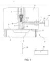
- the spark-ignited internal combustion engine 1 works according to the principle of internal mixture formation to burn a mixture of a gaseous fuel, here hydrogen, and air while performing work.
- the internal combustion engine 1 thus represents a hydrogen engine.
- the internal combustion engine 1 comprises at least one cylinder 2 in which a combustion chamber 3 between a longitudinally movable piston 4 and a cylinder head 6.
- the direction of movement of the piston 4 is shown schematically by the arrow 16.
- the piston 6 has a concave recess 5.
- FIG. 1 shows a schematic detailed view in section of just one cylinder head area of a cylinder 2 of the internal combustion engine 1.
- each of the cylinders 2 comprises a spark plug 9 arranged in the cylinder head 6, having an ignition tip 10, which is arranged in the second supply channel 11 opening into the combustion chamber.
- the opening of the second supply channel 11 into the combustion chamber 3 is identified by the reference number 12.
- the ignition tip 10 is arranged at a distance from the opening 12 of the second supply channel 11 into the combustion chamber 3.
- each of the cylinders 2 comprises an injection valve 7 arranged in the cylinder head 6, which can be designed as a control valve.
- the injection valve 7 is arranged at a distance from the combustion chamber 3 in a first supply channel 8.
- the first supply channel 8 opens indirectly into the combustion chamber 3 via the second supply channel 11.
- the injection valve 7 is in fluid connection with a hydrogen storage device 14 via a line 15.
- the first feed channel 8 opens into the second feed channel 11 between the ignition tip 10 and the opening 12 of the second feed channel 11 in the combustion chamber 3.
- the opening of the first feed channel 8 into the second feed channel 11 is identified by the reference number 13.
- the opening 12 of the second feed channel 11 into the combustion chamber 3 is located in the middle of the combustion chamber roof 17.
- the arrangement of the spark plug 9 and direct injection valve 7 according to the invention offers the particular advantage that these components are subjected to less thermal stress due to the setback. Accordingly, the spark plug 9 achieves a longer service life and the direct injection valve 7 can be constructed more cost-effectively.
- the internal combustion engine 3 further comprises charge exchange valves on each cylinder 2 for supplying air (air inlet valves) into the combustion chamber 3 and charge exchange valves for Discharge of exhaust gas (exhaust valves) from the combustion chamber 3, which are not shown in each case and can be designed in a manner known per se.
- the gas injection valve 7 is in signal connection with an engine control device 20 and is controlled by it.
- the engine control device 20 can be the engine control unit.
- the engine control device 20 is designed to carry out a gas injection of the gaseous fuel by means of the injection valve during an intake process and preferably to end it before the start of the compression phase. To this end, the engine control device 20 controls the gas injection valve 20 accordingly in order to open or close it.
- the mixture at the spark plug tip 10 is "richer", which increases the ignition readiness.
- the combustion directly at the spark plug initiates, similar to a spark plug with a pre-chamber, a propagation of the combustion with high energy in the main combustion chamber 3 via the feed channel 11, much greater than the ignition energy of a spark plug, and ensures that even lean mixtures in the combustion chamber 3 with a high lambda burn through completely.
- the arrangement of the spark plug 9 and the injection valve 7 set back from the combustion chamber 3 thus leads to a hydrogen enrichment in the second supply channel 11 and, upon ignition, to a type of "ignition jet" that propagates into the combustion chamber 3 via the feed channel 11. Because a reduced lambda always prevails at the spark plug 9 in the design shown, even very lean mixtures in the combustion chamber 3 are still reliably and completely burned via the "ignition jet”. This principle also makes it possible to dispense with the throttle valve, as already mentioned above.
- the engine control unit also regulates the "driver's request” in a known manner, i.e. torque and/or speed.
- the "amount of fuel to be injected” depends on the "accelerator pedal position", but takes into account the amount of combustion air (lambda).
- the air mass and, in the case of exhaust gas recirculation, the exhaust gas mass are also measured.
- the nitrogen oxide emissions can also be influenced. Basically, the higher the lambda, the lower the nitrogen oxide emissions.
- the internal combustion engine 1 can also have an exhaust gas recirculation system based on the donor cylinder principle, which is designed to recirculate exhaust gas from a subset of the cylinders 2 of the internal combustion engine 1 to an intake side.
- an exhaust gas recirculation system based on the donor cylinder principle, which is designed to recirculate exhaust gas from a subset of the cylinders 2 of the internal combustion engine 1 to an intake side.
- the entire exhaust gas from a cylinder is led directly back to the intake side. This achieves a stable exhaust gas recirculation rate (100/6).
- the exhaust gas turbocharger then only receives the exhaust gas mass from 5 cylinders.
- the exhaust gas recirculation line can usually also be switched off with a shut-off valve.
- the recirculated exhaust gas can also be cooled.
- a cylinder head for a diesel engine with a common rail injector and so-called side feed connection can be manufactured from a blank for the cylinder head, as well as the cylinder head 6 for the hydrogen engine or the internal combustion engine 1 according to Figure 1 .
- Such an internal combustion engine 1 or such a hydrogen engine is not only suitable for motor vehicles (trucks and buses), but is also suitable as a generator drive motor for power generation or for maritime applications. If the hydrogen is regenerative
- the internal combustion engine 1 can be described as a CO2 -neutral internal combustion engine and can make a significant contribution to low-emission electricity generation, particularly during periods of low light.
Landscapes
- Engineering & Computer Science (AREA)
- Chemical & Material Sciences (AREA)
- Combustion & Propulsion (AREA)
- Mechanical Engineering (AREA)
- General Engineering & Computer Science (AREA)
- Chemical Kinetics & Catalysis (AREA)
- General Chemical & Material Sciences (AREA)
- Oil, Petroleum & Natural Gas (AREA)
- Combustion Methods Of Internal-Combustion Engines (AREA)
- Output Control And Ontrol Of Special Type Engine (AREA)
Description
- Die Erfindung betrifft eine fremdgezündete Brennkraftmaschine mit innerer Gemischbildung zur Verbrennung eines Gemischs aus einem gasförmigen Kraftstoff und Luft unter Arbeitsleistung. Der gasförmige Kraftstoff kann vorzugsweise Wasserstoff sein. Die Erfindung betrifft ferner ein Kraftfahrzeug, vorzugsweise ein Nutzfahrzeug, mit einer solchen Brennkraftmaschine sowie die Verwendung einer solchen fremdgezündeten Brennkraftmaschine als Generatorantriebsmotor zur Stromerzeugung oder für maritime Anwendungen.
- Wasserstoff kann als Kraftstoff wegen seiner chemischen Eigenschaften große Bedeutung gewinnen und in Verbrennungsmotoren besonders vorteilhaft zur Drehmomenterzeugung genutzt werden. Entsprechend sind aus dem Stand der Technik bereits Wasserstoffverbrennungsmotoren bekannt. Dies sind Verbrennungsmotoren, die mit Wasserstoff als Kraftstoff betrieben werden. Grundlage ist die Knallgasreaktion (zwei Teile Wasserstoff mit einem Teil Sauerstoff) in einem Kolbenrotationszylinder. Das Grundkonzept derartiger Verbrennungsmotoren entspricht somit dem herkömmlicher Hubkolbenmotoren mit einem oder mehreren Zylindern. Lediglich beispielhaft wird auf die Dokumente
EP 1 647 684 A2 undDE 103 59 445 A1 verwiesen. - Ein anderes Beispiel ist aus dem
DE 10 2009 037160 A1 bekannt. - Für die Verwendung von Wasserstoff als Brennstoff werden üblicherweise modifizierte OttoMotoren als fremdgezündete Brennkraftmaschinen verwendet, wobei auch Wasserstoffverbrennungsmotoren bekannt sind, die nach dem Dieselprozess arbeiten. Bei den als fremdgezündete Brennkraftmaschinen arbeitenden Wasserstoffverbrennungsmotoren wird der Wasserstoff mittels einer Düse in den Brennraum eingebracht und mit einer Zündkerze gezündet. Dabei bildet sich eine Flammenfront aus, die sich von der Zündkerze in Richtung auf die Zylinderwand ausbreitet.
- Betreffend die Gemischbildung sind einerseits Wasserstoffverbrennungsmotoren bekannt, die mit äußerer Gemischbildung (Saugrohreinspritzung) arbeiten, als auch Wasserstoffverbrennungsmotoren, die mit innerer Gemischbildung (Direkteinblasung) arbeiten.
- Bei der äußeren Gemischbildung wird der unter Druck gespeicherte Wasserstoff mit geringem Überdruck gasförmig in das Ansaugrohr vor die Einlassventile eingeblasen. Bei der inneren Gemischbildung wird gasförmiger Wasserstoff unter Druck direkt in den Verbrennungsraum eingeblasen. Das Ladungsgemisch wird während der Kompressionsphase deutlich erwärmt und dann mit einer Zündkerze gezündet. Neben Wasserstoffmotoren sind weiterhin Erdgas- und Biogasmotoren sowie die Verwendung anderer Brenngase bekannt.
- Die Verbrennungsgeschwindigkeit von Wasserstoff liegt im Bereich von 200 m/s und ist bei gleichen Umgebungsbedingungen wesentlich höher als die Verbrennungsgeschwindigkeit der Brennstoffe Diesel und Benzin (ca. 20 m/s). Ähnlich wie bei herkömmlichen Verbrennungsmotoren können auch bei Wasserstoffmotoren Verbrennungsanomalien wie Klopfen, Glüh- bzw. Frühzündung oder Rückzündung auftreten. Verbrennungsanomalien entstehen bevorzugt an "Hot-Spots", d. h. an besonders heißen Stellen des Brennraums. Kritische Brennraumbereiche sind insbesondere die Zündkerze bzw. der Bereich um die Zündkerze, der Auslassventilteller, Ventilstege sowie das Brennraumdach.
- Entsprechend ist bei den aus dem Stand der Technik bekannten Wasserstoffverbrennungsmotoren oftmals ein Nachteil, dass die Komponenten im Brennraum, insbesondere die Zündkerze und das Einblasventil, einer hohen thermischen Belastung ausgesetzt sind, was sich nachteilig auf deren Funktion und Lebensdauer auswirkt.
- Zur Lösung dieses Problems schlägt die
WO 2015/138987 A1 einen Einspritz-Zündapparat mit einer Vorkammer vor, wobei die Vorkammer in Fluidverbindung mit einem Brennraum eines Verbrennungsmotors steht. Diese kann dabei als integrierte, verschraubte, einzelne Einheit ausgeführt werden, die für den Betrieb von Hochleistungs-Direkteinspritzmotoren mit Fremdzündung mit gasförmigen Kraftstoffen in verdünnten oder mageren Verhältnissen geeignet ist. Ferner offenbart dieWO 2015/138987 A1 auch Verfahren für Verbrennungsprozesse zum Betrieb eines fremdgezündeten Motors mit Direkteinspritzung und magerer Verbrennung, wobei Einspritzereignisse während des Ansaug- und Verdichtungstakts in einem Motor erfolgen sollen. - Weiterhin offenbart die
US 3 572 297 A einen Verbrennungsmotor, der durch direkte Einspritzung von Wasserstoff in seine Zylinder betrieben wird. Hierbei wird Wasserstoff mit einem Teil der Luft in den Zylindern gemischt, um ein brennbares Gemisch zu bilden, das gleichzeitig mit der Einspritzung über einen Teil des Expansionstakts und in einigen Fällen über einen Teil des Verdichtungstakts gezündet und verbrannt wird. Für die Einspritzung des Wasserstoffs werden Doppeltellerventile verwendet, die sich in Abhängigkeit von den erfassten Motorbetriebsparametern öffnen und schließen. - Aus der
FR 3 061 743 A1 - Es ist eine Aufgabe der Erfindung, eine verbesserte Brennkraftmaschine zur Verbrennung eines Gemischs aus einem gasförmigen Kraftstoff, vorzugsweise Wasserstoff, und Luft bereitzustellen, mit der Nachteile herkömmlicher mit gasförmigem Kraftstoff betriebener Brennkraftmaschinen vermieden werden können. Die Aufgabe der Erfindung ist es insbesondere, eine solche Brennkraftmaschine bereitzustellen, die die thermische Belastung von Komponenten im Brennraum verringert.
- Diese Aufgaben werden durch eine fremdgezündete Brennkraftmaschine mit den Merkmalen des unabhängigen Anspruchs gelöst. Vorteilhafte Ausführungsformen und Anwendungen der Erfindung sind Gegenstand der abhängigen Ansprüche und werden in der folgenden Beschreibung unter teilweiser Bezugnahme auf die Figuren näher erläutert.
- Gemäß einem allgemeinen Gesichtspunkt der Erfindung wird eine fremdgezündete Brennkraftmaschine mit innerer Gemischbildung zur Verbrennung eines Gemischs aus einem gasförmigen Kraftstoff und Luft unter Arbeitsleistung bereitgestellt. Die fremdgezündete Brennkraftmaschine (nachfolgend auch kurz als Brennkraftmaschine oder Verbrennungsmotor bezeichnet) umfasst mindestens einen Zylinder, in dem ein Brennraum zwischen einem längsbeweglich angeordneten Kolben und einem Zylinderkopf begrenzt ist. Die Brennkraftmaschine umfasst ferner in an sich bekannter Weise Ladungswechselventile zum Zuführen von Luft (Lufteinlassventile) in den Brennraum und Ladungswechselventile zum Abführen von Abgas (Auslassventile) aus dem Brennraum.
- Jeder der mindestens einen Zylinder umfasst ein im Zylinderkopf angeordnetes Einblasventil und eine im Zylinderkopf angeordnete Zündkerze.
- Das Einblasventil bzw. Einblaseventil dient zum Zuleiten des gasförmigen Brennstoffes in den Brennraum, wo sich der gasförmige Brennstoff mit Luft vermischt.
- Erfindungsgemäß ist das Einblasventil beabstandet zum Brennraum in einem in den Brennraum unmittelbar mündenden Zuführkanal angeordnet. Dieser Zuführkanal wird nachfolgend auch als erster Zuführkanal bezeichnet zur besseren Unterscheidung von einem nachfolgend beschriebenen weiteren Zuführkanal, der als zweiter Zuführkanal bezeichnet wird. Mit anderen Worten ragt das Einblasventil nicht in den Brennraum hinein oder grenzt direkt an diesen an, sondern ist im Zylinderkopf zurückgesetzt hierzu angeordnet. Ein durch das Einblasventil in Richtung Brennraum austretender gasförmiger Kraftstoff tritt somit nicht direkt in den Brennraum ein, sondern muss zumindest noch eine Wegstrecke im Zuführkanal zurücklegen, bevor der gasförmige Kraftstoff in den Brennraum eintreten kann. Entsprechend des Prinzips der inneren Gemischbildung wird das Einblasventil (oder Einblaseventil) auch als Direkteinblasventil bezeichnet, weil der gasförmige Kraftstoff unter Druck direkt über den Zuführkanal oder die Zuführkanäle in dem Brennraum eingeblasen wird (innere Gemischbildung) und nicht, wie bei der äußeren Gemischbildung, mit geringem Überdruck gasförmig in das Ansaugrohr vor die Einlassventile eingeblasen wird.
- Die Brennkraftmaschine umfasst ferner eine im Zylinderkopf angeordnete, eine Zündspitze aufweisende Zündkerze, die in einem in den Brennraum mündenden weiteren Zuführkanal, nachfolgend als zweiter Zuführkanal bezeichnet, angeordnet ist, wobei die Zündspitze beabstandet zur Mündung des zweiten Zuführkanals in den Brennraum angeordnet ist. Mit anderen Worten ragen die Zündkerze und deren Zündspitze nicht in den Brennraum hinein, sondern sind im Zylinderkopf zurückgesetzt hierzu angeordnet.
- Zusammenfassend ragen sowohl die Zündkerze als auch das Einblasventil nicht unmittelbar in den eigentlichen Brennraum des Kolbens, sondern sind im Zylinderkopf zurückgesetzt. Die erfindungsgemäße Anordnung von Zündkerze und Direkteinblasventil bietet den besonderen Vorzug, dass diese Bauteile durch die Zurücksetzung thermisch weniger belastet werden. Entsprechend erreicht die Zündkerze höhere Standzeiten und das Direkteinblasventil kann kostengünstiger konstruiert werden.
- Da erfindungsgemäß somit das Direkteinblasventil nicht bis in den Brennraum hineinragt, ergeben sich ferner konstruktiv mehr Freiheitsgrade für das Direkteinblasventil, um die Performance zu optimieren, und es besteht auch nicht die Notwendigkeit, den Zylinderkopf bei Einsatz von Wasserstoff ausgehend von einem flüssigen Kraftstoff aufwändig umzukonstruieren. Ein weiterer besonderer Vorteil ist, dass die zurückgesetzte Anordnung von Gaseinblasventil und Zündkerzenspitze es ermöglicht - wie nachfolgend noch detaillierter beschrieben wird - magere Gemische sauber zu verbrennen. Der Grund ist, dass beim Ansaugvorgang im Bereich des zweiten Zuführkanals ein fetteres Gemisch (niedrigeres Lambda) als im Brennraum erzeugbar ist, was von der Zündkerze gezündet werden kann. Diese erzeugt einen Zündstrahl durch den zweiten Zuführkanal hin zum Brennraum, wodurch auch magere Gemische mit großem Lambda möglichst vollständig und sauber verbrannt werden können. Dies ermöglicht wiederum geringe Stickoxidemissionen.
- Gemäß einer besonders bevorzugten Ausführungsform ist der gasförmige Kraftstoff Wasserstoff. Ferner kann das Einblasventil mit einer Wasserstoff-Speichereinrichtung in Fluidverbindung stehen. Neben dieser beispielhaft hervorgehobenen Anwendung kann der gasförmige Kraftstoff jedoch auch ein anderer gasförmiger Kraftstoff sein.
- Der erste Zuführkanal mündet direkt in den Brennraum, somit nicht mittelbar über den zweiten Zuführkanal in den Brennraum mündet. Gemäß diesem Aspekt münden die beiden Zuführkanäle an unterschiedlichen Stellen in den Brennraum. Hierbei dient der zweite Zuführkanal somit zur Zufuhr von gasförmigem Kraftstoff und Luft zur zum Brennraum zurückgesetzten Zündspitze.
- Ferner kann der zweite Zuführkanal in einem mittleren Bereich eines Brennraumdachs in den Brennraum münden. Besonders vorteilhaft ist, wenn der zweite Zuführkanal mittig am Brennraumdach in den Brennraum mündet. Vorliegend bildet der Zylinderkopf das Brennraumdach aus, insbesondere der dem Kolben zugewandte Bereich des Zylinderkopfs.
- Vorstehend wurde bereits ausgeführt, dass der Bereich, der zwischen dem längsbeweglich angeordneten Kolben und dem Zylinderkopf begrenzt ist, vorliegend als Brennraum bezeichnet wird. Der zweite Zuführkanal und der erste Zuführkanal werden nicht als Teil des Brennraums angesehen, auch wenn im zweiten Zuführkanal die Verbrennung gezündet bzw. initiiert wird, ähnlich einer Zündkerze mit Vorkammer.
- Unter dem Brennraumdach wird die den Zylinder begrenzende Zylinderkopfwandung verstanden, durch welche hindurch der Ladungswechsel (Zuführen von Luft und Brennstoff, Ausstoß des Abgases) stattfindet.
- Die fremdgezündete Brennkraftmaschine umfasst eine Motorsteuerungseinrichtung, die ausgebildet ist, eine Gaseinblasung des gasförmigen Kraftstoffes mittels des Einblasventils während eines Ansaugvorgangs durchzuführen und vor Beginn der Kompressionsphase zu beenden.
- Gemäß diesem Aspekt kann beispielsweise die Gaseinblasung des gasförmigen Kraftstoffes während des Ansaugvorgangs der Brennkraftmaschine erfolgen, wobei die Einlassventile offen sind und der Kolben sich nach unten bewegt, d. h. vom Zylinderkopf weg. Die Motorsteuereinrichtung kann das Gaseinblaseventil so ansteuern, dass es schließt, bevor die Kompressionsphase im Zylinder beginnt.
- Dies bietet den Vorzug, dass sich im Bereich der Zündkerzenspitze ein großer Anteil, vorzugsweise nahezu 100 % gasförmiger Kraftstoff, befindet. Mit dem Kompressionstakt wird das Wasserstoff-Luft-Gemisch aus dem Brennraum auch in die Zuführkanäle gedrückt, der dort vorhandene gasförmige Kraftstoff komprimiert und auch mit der im Zylinder bzw. Brennraum bestehenden Ladung vermischt. In jedem Fall wird aber erreicht, dass das Gemisch an der Zündkerzenspitze "fetter" ist, wodurch die Zündwilligkeit erhöht wird. Die Verbrennung unmittelbar an der Zündkerze initiiert, ähnlich einer Zündkerze mit Vorkammer, über den zweiten Zuführkanal eine Fortpflanzung der Verbrennung mit hoher Energie im (Haupt-)Brennraum und stellt sicher, dass auch magere Gemische mit großem Lambda vollständig durchbrennen.
- Weil auch magere Gemische sauber verbrannt werden können, wurde im Rahmen der Erfindung überraschend festgestellt, dass eine im Ansaugtrakt angeordnete Drosselklappe nicht unbedingt notwendig ist, wie es sonst für fremdgezündete Brennkraftmaschinen üblich ist. Entsprechend kann gemäß einem vorteilhaften Aspekt der Erfindung vorgesehen sein, dass die fremdgezündete Brennkraftmaschine keine Drosselklappe aufweist. Durch den Entfall der Drosselklappe lässt sich der Wirkungsgrad der Brennkraftmaschine verbessern. Im Falle einer Abgasrückführung und der Kenntnis der Abgasmasse kann auch diese als Regelgröße berücksichtigt werden.
- Gemäß einer weiteren Ausführungsform kann die Brennkraftmaschine ferner eine Abgasrückführung nach dem Spenderzylinderprinzip umfassen, die ausgebildet ist, Abgas einer Teilmenge der Zylinder der Brennkraftmaschine auf eine Ansaugseite rückzuführen. Damit lassen sich, insbesondere bei Wasserstoffverbrennungsmotoren, die Stickoxidemissionen so weit reduzieren, dass zur Einhaltung der aktuellen Grenzwerte zum Teil keine Abgasnachbehandlungseinrichtungen notwendig werden. Aufgrund der Abgasrückführung ist auch eine Erhöhung des Verdichtungsverhältnisses möglich, wodurch der Wirkungsgrad des Motors weiter gesteigert werden kann. Ferner kann vorgesehen sein, das rückgeführte Abgas zu kühlen, beispielsweise mittels einer Kühleinrichtung und/oder eines mit der Abgasrückführung thermisch gekoppelten Kühlkreislaufs.
- Zur Realisierung einer Abgasrückführung nach dem Spenderzylinderprinzip kann die Brennkraftmaschine beispielsweise mindestens einen Abgasturbolader aufweisen, welcher einen Verdichter sowie eine Turbine umfasst sowie eine Ladeluftleitung zur Zuführung von verdichteter Luft zur Brennkraftmaschine. Hierbei umfasst der mindestens eine Zylinder der Brennkraftmaschine eine erste Zylindergruppe und eine zweite Zylindergruppe, wobei die zweite Zylindergruppe nach dem Spenderzylinderprinzip arbeitet. Hierbei ist eine Abgassammelleitung vorgesehen, welche einen ersten Abschnitt zum Abgassammeln der ersten Zylindergruppe sowie einen zweiten Abschnitt zum Abgassammeln der zweiten Zylindergruppe aufweist. Ferner ist eine erste Abgasleitung vorgesehen, welche den ersten Abschnitt der Abgassammelleitung mit der Turbine verbindet, mit einer Rückführungsleitung zur Abgasrückführung aus dem zweiten Abschnitt der Abgassammelleitung in die Ladeluftleitung.
- Ferner kann der Kolben der fremdgezündeten Brennkraftmaschine eine konkave Mulde aufweisen. Optional kann in der konkaven Mulde eine konvexe Erhebung vorgesehen sein. Diese Maßnahmen verbessern den Wirkungsgrad.
- Gemäß einem weiteren Aspekt kann der erste Zuführkanal einen konstanten Querschnitt aufweisen, wobei vorzugsweise die Länge des ersten Zuführkanals größer als dessen Querschnittsbreite ist. Ferner kann der zweite Zuführkanal einen konstanten Querschnitt aufweisen, wobei vorzugsweise die Länge des zweiten Zuführkanals größer als dessen Querschnittsbreite ist. Ferner kann der erste Zuführkanal und/oder der zweite Zuführkanal durch eine Bohrung oder einen Kernguss hergestellt sein.
- Die Erfindung betrifft ferner ein Kraftfahrzeug mit einer fremdgezündeten Brennkraftmaschine wie in diesem Dokument beschrieben. Das Kraftfahrzeug kann ein Nutzfahrzeug sein, wie beispielsweise ein Lastkraftwagen oder Omnibus.
- Weitere bevorzugte Anwendungen der Erfindung umfassen die Verwendung einer fremdgezündeten Brennkraftmaschine, wie in diesem Dokument beschrieben, als Brennkraftmaschine, insbesondere Generatorantriebsmotor, zur Stromerzeugung oder für maritime Anwendungen. Die zuvor beschriebenen bevorzugten Ausführungsformen, Aspekte und Merkmale der Erfindung sind beliebig miteinander kombinierbar. Weitere Einzelheiten und Vorteile der Erfindung werden im Folgenden unter Bezug auf die beigefügte Zeichnung beschrieben. Es zeigt:
- Figur 1
- eine schematische Detailansicht im Schnitt eines Zylinderkopfbereichs einer Brennkraftmaschine nicht gemäß einer Ausführungsform der Erfindung.
- Die fremdgezündete Brennkraftmaschine 1 arbeitet nach dem Prinzip der inneren Gemischbildung zur Verbrennung eines Gemischs aus einem gasförmigen Kraftstoff, hier Wasserstoff, und Luft unter Arbeitsleistung. Die Brennkraftmaschine 1 stellt somit einen Wasserstoffmotor dar. Die Brennkraftmaschine 1 umfasst mindestens einen Zylinder 2, in dem ein Brennraum 3 zwischen einem längsbeweglich angeordneten Kolben 4 und einem Zylinderkopf 6 begrenzt ist. Die Bewegungsrichtung des Kolbens 4 ist durch den Pfeil 16 schematisch dargestellt. Der Kolben 6 weist eine konkave Mulde 5 auf.
-
Figur 1 zeigt eine schematische Detailansicht im Schnitt lediglich eines Zylinderkopfbereichs eines Zylinders 2 der Brennkraftmaschine 1. Jedoch umfasst jeder der Zylinder 2 eine im Zylinderkopf 6 angeordnete, eine Zündspitze 10 aufweisende Zündkerze 9, die in dem in den Brennraum mündenden zweiten Zuführkanal 11 angeordnet ist. Die Mündung des zweiten Zuführkanals 11 in den Brennraum 3 ist mit dem Bezugszeichen 12 gekennzeichnet. Hierbei ist die Zündspitze 10 beabstandet zur Mündung 12 des zweiten Zuführkanals 11 in den Brennraum 3 angeordnet. - Ferner umfasst jeder der Zylinder 2 ein im Zylinderkopf 6 angeordnetes Einblasventil 7, das als Regelventil ausgeführt sein kann. Das Einblasventil 7 ist beabstandet zum Brennraum 3 in einem ersten Zuführkanal 8 angeordnet. Der erste Zuführkanal 8 mündet mittelbar in den Brennraum 3 über den zweiten Zuführkanal 11. Das Einblasventil 7 steht mit einer Wasserstoff-Speichereinrichtung 14 über eine Leitung 15 in Fluidverbindung.
- Der erste Zuführkanal 8 mündet zwischen der Zündspitze 10 und der Mündung 12 des zweiten Zuführkanals 11 in den Brennraum 3 in den zweiten Zuführkanal 11. Die Mündung des ersten Zuführkanals 8 in den zweiten Zuführkanal 11 ist mit dem Bezugszeichen 13 gekennzeichnet. Die Mündung 12 des zweiten Zuführkanals 11 in den Brennraum 3 befindet sich mittig am Brennraumdach 17.
- Aufgrund seiner hohen Zündfähigkeit ist vorgesehen, den Wasserstoff direkt in den Verbrennungsraum 3 einzubringen, was über die Zuführkanäle 8, 11 erfolgt.
- Zusammenfassend ragen sowohl die Zündkerze 9 als auch das Einblasventil 7 nicht unmittelbar in den eigentlichen Brennraum 3 des Kolbens, sondern sind im Zylinderkopf 6 zurückgesetzt und somit beabstandet zum eigentlichen (Haupt-)Brennraum 3 angeordnet. Die erfindungsgemäße Anordnung von Zündkerze 9 und Direkteinblasventil 7 bietet den besonderen Vorzug, dass diese Bauteile durch die Zurücksetzung thermisch weniger belastet werden. Entsprechend erreicht die Zündkerze 9 höhere Standzeiten, und das Direkteinblasventil 7 kann kostengünstiger konstruiert werden.
- Die Brennkraftmaschine 3 umfasst ferner an jedem Zylinder 2 Ladungswechselventile zum Zuführen von Luft (Lufteinlassventile) in den Brennraum 3 und Ladungswechselventile zum Abführen von Abgas (Auslassventile) aus dem Brennraum 3, die jeweils nicht dargestellt sind und in an sich bekannter Weise ausgeführt sein können.
- Das Gaseinblasventil 7 steht in Signalverbindung mit einer Motorsteuerungseinrichtung 20 und wird von dieser angesteuert. Die Motorsteuerungseinrichtung 20 kann das Motorsteuergerät sein. Die Motorsteuereinrichtung 20 ist ausgebildet, eine Gaseinblasung des gasförmigen Kraftstoffes mittels des Einblasventils während eines Ansaugvorgangs durchzuführen und vorzugsweise vor Beginn der Kompressionsphase zu beenden. Hierzu steuert die Motorsteuereinrichtung 20 das Gaseinblasventil 20 entsprechend an, um dieses zu öffnen bzw. zu schließen.
- Nachfolgend wird ein Zündbetrieb der Brennkraftmaschine beschrieben.
- Besonders vorteilhaft ist ein direktes Einbringen des Wasserstoffs in den Brennraum 3 während des Ansaugtaktes. Das Einbringen erfolgt in Strömungsrichtung nach dem Einlassventil (nicht dargestellt). Die Gaseinblasung erfolgt während des Ansaugvorgangs der Brennkraftmaschine 1, d. h. wenn das Einlassventil (nicht dargestellt) für Luft offen ist und der Kolben 4 sich nach unten bewegt. Hierzu wird das Einblasventil 7 in die Offenstellung gebracht. Das Einblasventil 7 wird wieder geschlossen, bevor die Kompressionsphase im Zylinder 2 beginnt. Damit sind im Bereich der Zündkerzenspitze 10 nahezu 100 % Wasserstoff, wenn die Kompressionsphase beginnt, da sich dort der Wasserstoff durch die Zuführkanäle 8, 11 bevorzugt ansammelt. Ein Teil des Wasserstoffs gelangt über die Zuführkanäle 8, 11 in den Brennraum und vermischt sich dort mit der durch die Einlassventile (nicht dargestellt) eingetretenen Luft (innere Gemischbildung). Mit dem Kompressionstakt wird das Wasserstoff-Luft-Gemisch auch in die Kanäle 8 und 11 gedrückt, der dort vorhandene Wasserstoff komprimiert und auch mit der im Zylinder bestehenden Ladung vermischt.
- In jedem Fall wird aber erreicht, dass das Gemisch an der Zündkerzenspitze 10 "fetter" ist, wodurch die Zündwilligkeit erhöht wird. Die Verbrennung unmittelbar an der Zündkerze initiiert, ähnlich einer Zündkerze mit Vorkammer, über den Zuführkanal 11 eine Fortpflanzung der Verbrennung mit hoher Energie im Hauptbrennraum 3, sehr viel größer als die Zündenergie einer Zündkerze, und stellt sicher, dass auch magere Gemische im Brennraum 3 mit großem Lambda vollständig durchbrennen.
- Die vom Brennraum 3 zurückgesetzte Anordnung der Zündkerze 9 und des Einblasventils 7 führt somit zu einer Wasserstoffanreicherung im zweiten Zuführkanal 11 und bei Zündung zu einer Art "Zündstrahl", der sich über den Zuführkanal 11 in den Brennraum 3 fortpflanzt. Dadurch, dass bei der gezeigten Konstruktion an der Zündkerze 9 immer ein verringertes Lambda vorherrscht, werden auch sehr magere Gemische im Brennraum 3 über den "Zündstrahl" noch zuverlässig und vollständig verbrannt. Dieses Prinzip ermöglicht auch den Wegfall der Drosselklappe, wie vorstehend bereits erwähnt wurde.
- Das Motorsteuergerät regelt ferner in an sich bekannter Weise den "Fahrerwunsch", d. h. Drehmoment und/oder Drehzahl. Im Falle des Wasserstoffverbrennungsmotors ist die "einzublasende Kraftstoffmenge" abhängig von der "Gaspedalstellung", aber unter Berücksichtigung der Verbrennungsluftmenge (Lambda). Dazu wird die Luftmasse und im Falle der Abgasrückführung auch die Abgasmasse gemessen. Abhängig vom Luftverhältnis Lambda lassen sich auch die Stickoxidemissionen beeinflussen. Grundsätzlich gilt, je höher Lambda, umso geringer die Stickoxidemission.
- Die Brennkraftmaschine 1 kann ferner eine Abgasrückführung nach dem Spenderzylinderprinzip aufweisen, die ausgebildet ist, Abgas einer Teilmenge der Zylinder 2 der Brennkraftmaschine 1 auf eine Ansaugseite rückzuführen. Dabei wird, z. B. im Falle eines 6-Zylindermotors, das gesamte Abgas eines Zylinders direkt zurück auf die Ansaugseite geführt. Damit wird eine stabile Abgasrückführquote (100/6) erreicht. Der Abgasturbolader bekommt dann nur noch die Abgasmasse von 5 Zylindern. In der Regel ist die Abgasrückführleitung mit einem Absperrventil auch abschaltbar. Das rückgeführte Abgas kann ferner noch gekühlt werden.
- Durch die zurückgesetzte Anordnung von Zündkerze 9 und Einblasventil 7 lassen sich bestehende Motoren, insbesondere Common-Rail-Dieselmotoren mit Side-Feed-Injektoren, relativ einfach auf einen Betrieb mit Wasserstoff umrüsten. Aufgrund der konstruktiven Ähnlichkeit ist es möglich, gleiche Zylinderkopfgußteile für Diesel- und Wasserstoffmotoren einzusetzen. Beispielsweise kann aus einem Rohteil für den Zylinderkopf wahlweise sowohl ein Zylinderkopf für einen Dieselmotor mit Commonrail-Injektor und sog. Sidefeed-Anschluss gefertigt werden als auch der Zylinderkopf 6 für den Wasserstoffmotor bzw. die Brennkraftmaschine 1 gemäß
Figur 1 . - Eine derartige Brennkraftmaschine 1 bzw. ein derartiger Wasserstoffmotor eignet sich nicht nur für Kraftfahrzeuge (LKW und Busse), sondern ist auch geeignet als Generatorantriebsmotor zur Stromerzeugung oder für maritime Anwendungen. Wenn der Wasserstoff regenerativ erzeugt wurde, lässt sich die Brennkraftmaschine 1 als CO2-neutrale Brennkraftmaschine bezeichnen und kann besonders in Dunkelflautezeiten wesentlich zur emissionsarmen Stromerzeugung beitragen.
- Obwohl die Erfindung unter Bezugnahme auf bestimmte Ausführungsbeispiele beschrieben worden ist, ist es für einen Fachmann ersichtlich, dass verschiedene Änderungen ausgeführt werden können, ohne den Bereich der Erfindung zu verlassen. Folglich soll die Erfindung nicht auf die offenbarten Ausführungsbeispiele begrenzt sein, sondern soll alle Ausführungsbeispiele umfassen, die in den Bereich der beigefügten Patentansprüche fallen.
-
- 1
- Brennkraftmaschine
- 2
- Zylinder
- 3
- Brennraum
- 4
- Kolben
- 5
- Kolbenmulde
- 6
- Zylinderkopf
- 7
- Direkteinblasventil
- 8
- Erster Zuführkanal
- 9
- Zündkerze
- 10
- Zündspitze
- 11
- Zweiter Zuführkanal
- 12
- Mündung des zweiten Zuführkanals in Brennraum
- 13
- Mündung des ersten Zuführkanals in zweiten Zuführkanal
- 14
- Wasserstoff-Speichereinrichtung
- 15
- Gaszulauf
- 16
- Kolbenbewegungsrichtung
- 20
- Motorsteuerungseinrichtung
Claims (10)
- Fremdgezündete Brennkraftmaschine (1) mit innerer Gemischbildung zur Verbrennung eines Gemischs aus einem gasförmigen Kraftstoff und Luft unter Arbeitsleistung, umfassend
mindestens einen Zylinder (2), in dem ein Brennraum (3) zwischen einem längsbeweglich angeordneten Kolben (4) und einem Zylinderkopf (6) begrenzt ist, wobei jeder der mindestens einen Zylinder (2) umfasst:ein im Zylinderkopf (6) angeordnetes Direkteinblasventil (7), das beabstandet zum Brennraum (3) in einem in den Brennraum (3) unmittelbar mündenden ersten Zuführkanal (8) angeordnet ist; undeine im Zylinderkopf (6) angeordnete, eine Zündspitze (10) aufweisende Zündkerze (9), die in einem in den Brennraum mündenden zweiten Zuführkanal (11) angeordnet ist, wobei die Zündspitze (10) beabstandet zur Mündung (12) des zweiten Zuführkanals (11) in den Brennraum (3) angeordnet ist;eine Motorsteuerungseinrichtung (20), die ausgebildet ist, eine Gaseinblasung des gasförmigen Kraftstoffes mittels des Direkteinblasventils (7) während eines Ansaugvorgangs durchzuführen und vor Beginn der Kompressionsphase zu beenden;dadurch gekennzeichnet, dass der erste Zuführkanal (8) an einer anderen Stelle als der zweite Zuführkanal (11) in den Brennraum (3) mündet. - Fremdgezündete Brennkraftmaschine (1) nach Anspruch 1,a) wobei der gasförmige Kraftstoff Wasserstoff ist; und/oderb) wobei das Direkteinblasventil (7) mit einer Wasserstoff-Speichereinrichtung (14) in Fluidverbindung steht.
- Fremdgezündete Brennkraftmaschine (1) nach einem der vorhergehenden Ansprüche, wobei der zweite Zuführkanal (11) in einem mittleren Bereich eines Brennraumdachs (17) in den Brennraum (3) mündet, vorzugsweise mittig am Brennraumdach (17) in den Brennraum (3) mündet.
- Fremdgezündete Brennkraftmaschine (1) nach einem der vorhergehenden Ansprüche, wobei die Brennkraftmaschine keine Drosselklappe aufweist.
- Fremdgezündete Brennkraftmaschine nach einem der vorhergehenden Ansprüche, umfassend eine Abgasrückführung nach dem Spenderzylinderprinzip, die ausgebildet ist, Abgas einer Teilmenge der Zylinder der Brennkraftmaschine auf eine Ansaugseite rückzuführen.
- Fremdgezündete Brennkraftmaschine (1) nach einem der vorhergehenden Ansprüche, wobei der Kolben eine konkave Mulde (5) aufweist.
- Fremdgezündete Brennkraftmaschine nach Anspruch 6, wobei in der konkaven Mulde eine konvexe Erhebung vorgesehen ist.
- Kraftfahrzeug, vorzugsweise Nutzfahrzeug, wie beispielsweise ein Lastkraftwagen oder Omnibus, mit einer fremdgezündeten Brennkraftmaschine nach einem der vorhergehenden Ansprüche.
- Verwendung einer fremdgezündeten Brennkraftmaschine (1) gemäß einem der Ansprüche 1 bis 7 als Generatorantriebsmotor zur Stromerzeugung oder für maritime Anwendungen.
- Verwendung einer fremdgezündeten Brennkraftmaschine (1) gemäß einem der Ansprüche 1 bis 7, wobei der gasförmige Kraftstoff unter Druck direkt über den ersten Zuführkanal (8) in den Brennraum (3) eingeblasen wird.
Applications Claiming Priority (1)
| Application Number | Priority Date | Filing Date | Title |
|---|---|---|---|
| DE102019006019.9A DE102019006019A1 (de) | 2019-08-26 | 2019-08-26 | Fremdgezündete Brennkraftmaschine mit innerer Gemischbildung zur Verbrennung eines Gemischs aus einem gasförmigen Kraftstoff und Luft |
Publications (2)
| Publication Number | Publication Date |
|---|---|
| EP3786424A1 EP3786424A1 (de) | 2021-03-03 |
| EP3786424B1 true EP3786424B1 (de) | 2025-02-19 |
Family
ID=72234676
Family Applications (1)
| Application Number | Title | Priority Date | Filing Date |
|---|---|---|---|
| EP20192339.8A Active EP3786424B1 (de) | 2019-08-26 | 2020-08-24 | Fremdgezündete brennkraftmaschine mit innerer gemischbildung zur verbrennung eines gemischs aus einem gasförmigen kraftstoff und luft |
Country Status (2)
| Country | Link |
|---|---|
| EP (1) | EP3786424B1 (de) |
| DE (1) | DE102019006019A1 (de) |
Families Citing this family (3)
| Publication number | Priority date | Publication date | Assignee | Title |
|---|---|---|---|---|
| CN113719343B (zh) * | 2021-07-29 | 2022-12-23 | 东风商用车有限公司 | 分体侧置式射流点火系统 |
| CN113719375B (zh) * | 2021-07-29 | 2023-01-24 | 东风商用车有限公司 | 侧置式射流点火系统燃料供给结构 |
| DE102023116067A1 (de) * | 2023-06-20 | 2024-12-24 | Alstom Holdings | Fahrzeug und entsprechendes Verfahren |
Citations (1)
| Publication number | Priority date | Publication date | Assignee | Title |
|---|---|---|---|---|
| DE102009037160A1 (de) * | 2009-08-03 | 2011-06-22 | Er-System | Verfahren zum Betreiben eines Gasmotors, sowie Gasmotor |
Family Cites Families (7)
| Publication number | Priority date | Publication date | Assignee | Title |
|---|---|---|---|---|
| US3572297A (en) * | 1970-01-26 | 1971-03-23 | Schoeppel Roger J | Hydrogen fueled internal combustion engine |
| DE19622945A1 (de) * | 1996-06-07 | 1997-12-11 | Wtz Fuer Motoren Und Maschinen | Verfahren zum Betrieb von Brennkraftmaschinen |
| DE10359445A1 (de) * | 2003-12-17 | 2005-07-28 | Enginion Ag | Wasserstoff-Verbrennungsmotor |
| DE102004049589A1 (de) * | 2004-10-12 | 2006-04-20 | Bayerische Motoren Werke Ag | Wasserstoffmotor mit optimierter Kraftstoffeinblasvorrichtung |
| US9200560B2 (en) * | 2013-01-11 | 2015-12-01 | Caterpillar Inc. | Gaseous common rail fuel system and high compression ratio engine using same |
| WO2015138987A1 (en) * | 2014-03-14 | 2015-09-17 | Advanced Green Technologies, Llc | Pre-chamber injector-igniter for gaseous fuel combustion and associated systems and methods |
| FR3061743B1 (fr) * | 2017-01-12 | 2019-08-16 | Vianney Rabhi | Prechambre d'allumage a clapet |
-
2019
- 2019-08-26 DE DE102019006019.9A patent/DE102019006019A1/de active Pending
-
2020
- 2020-08-24 EP EP20192339.8A patent/EP3786424B1/de active Active
Patent Citations (1)
| Publication number | Priority date | Publication date | Assignee | Title |
|---|---|---|---|---|
| DE102009037160A1 (de) * | 2009-08-03 | 2011-06-22 | Er-System | Verfahren zum Betreiben eines Gasmotors, sowie Gasmotor |
Also Published As
| Publication number | Publication date |
|---|---|
| EP3786424A1 (de) | 2021-03-03 |
| DE102019006019A1 (de) | 2021-03-04 |
Similar Documents
| Publication | Publication Date | Title |
|---|---|---|
| DE10147529B4 (de) | Verfahren zum Betreiben einer mit selbstzündbarem Kraftstoff betriebenen Brennkraftmaschine | |
| WO2019068484A1 (de) | Verbrennungskraftmaschine für ein kraftfahrzeug | |
| EP3786424B1 (de) | Fremdgezündete brennkraftmaschine mit innerer gemischbildung zur verbrennung eines gemischs aus einem gasförmigen kraftstoff und luft | |
| DE102017120512B4 (de) | Verfahren zum Betreiben eines Wasserstoffmotors für ein Kraftfahrzeug | |
| DE102011056519A1 (de) | Diesel-Benzin-Hybridmotor | |
| DE102018109939A1 (de) | Verbrennungsmotor | |
| DE102018000706A1 (de) | Verfahren zum Betreiben einer Verbrennungskraftmaschine für ein Kraftfahrzeug | |
| DE102016218707A1 (de) | Hubkolben-Brennkraftmaschine | |
| DE102008045915A1 (de) | Brennkraftmaschine mit Vorkammerzündung | |
| DE2851504A1 (de) | Verfahren zum betreiben einer brennkraftmaschine mit innerer verbrennung und variablem verdichtungsverhaeltnis, sowie brennkraftmaschine zum durchfuehren des verfahrens | |
| EP3953574B1 (de) | Verfahren zum betreiben einer brennkraftmaschine | |
| WO2004101972A1 (de) | Verfahren zum betreiben einer brennkraftmaschine | |
| DE102012202080A1 (de) | Hubkolben-Brennkraftmaschine | |
| DE102017009613A1 (de) | Verfahren zum Betreiben einer Verbrennungskraftmaschine eines Kraftfahrzeugs, insbesondere eines Kraftwagens | |
| DE2602127A1 (de) | Mehrfach fremdgezuendeter verbrennungsmotor mit auspuffgasrueckfuehrung | |
| EP4028659B1 (de) | Verfahren zum betreiben einer brennkraftmaschine | |
| DE102009049755A1 (de) | Verfahren zum Betreiben einer Kolbenbrennkraftmaschine sowie Kolbenbrennkraftmaschine | |
| DE102015221325B4 (de) | Verfahren zum Betreiben einer Brennkraftmaschine und Brennkraftmaschine | |
| WO2021074173A1 (de) | Verfahren zum betreiben einer brennkraftmaschine | |
| DE102015223351A1 (de) | Verfahren zum Betreiben einer Brennkraftmaschine und Brennkraftmaschine | |
| DE102014019563A1 (de) | Verfahren zum Unterdrücken von irregulären Verbrennungen eines Ottomotors | |
| DE102016205875B4 (de) | Direkteinspritzende fremdgezündete Brennkraftmaschine mit im Zylinderrohr angeordneter Einspritzvorrichtung und Verfahren zum Betreiben einer derartigen Brennkraftmaschine | |
| DE102023203862B4 (de) | Verfahren zum Betreiben einer Hubkolben-Verbrennungskraftmaschine | |
| EP1007833B1 (de) | Verfahren zur zündung eines mehrzylinder-hubkolbengasmotors durch einblasen eines zündgases | |
| DE2307284B2 (de) | Viertakt-brennkraftmaschine mit fremdzuendung mit einem ueber einen durchlass verbundenem zylinderpaar |
Legal Events
| Date | Code | Title | Description |
|---|---|---|---|
| PUAI | Public reference made under article 153(3) epc to a published international application that has entered the european phase |
Free format text: ORIGINAL CODE: 0009012 |
|
| STAA | Information on the status of an ep patent application or granted ep patent |
Free format text: STATUS: THE APPLICATION HAS BEEN PUBLISHED |
|
| AK | Designated contracting states |
Kind code of ref document: A1 Designated state(s): AL AT BE BG CH CY CZ DE DK EE ES FI FR GB GR HR HU IE IS IT LI LT LU LV MC MK MT NL NO PL PT RO RS SE SI SK SM TR |
|
| AX | Request for extension of the european patent |
Extension state: BA ME |
|
| STAA | Information on the status of an ep patent application or granted ep patent |
Free format text: STATUS: REQUEST FOR EXAMINATION WAS MADE |
|
| 17P | Request for examination filed |
Effective date: 20210831 |
|
| RBV | Designated contracting states (corrected) |
Designated state(s): AL AT BE BG CH CY CZ DE DK EE ES FI FR GB GR HR HU IE IS IT LI LT LU LV MC MK MT NL NO PL PT RO RS SE SI SK SM TR |
|
| STAA | Information on the status of an ep patent application or granted ep patent |
Free format text: STATUS: EXAMINATION IS IN PROGRESS |
|
| 17Q | First examination report despatched |
Effective date: 20220905 |
|
| GRAP | Despatch of communication of intention to grant a patent |
Free format text: ORIGINAL CODE: EPIDOSNIGR1 |
|
| STAA | Information on the status of an ep patent application or granted ep patent |
Free format text: STATUS: GRANT OF PATENT IS INTENDED |
|
| INTG | Intention to grant announced |
Effective date: 20240930 |
|
| GRAS | Grant fee paid |
Free format text: ORIGINAL CODE: EPIDOSNIGR3 |
|
| GRAA | (expected) grant |
Free format text: ORIGINAL CODE: 0009210 |
|
| STAA | Information on the status of an ep patent application or granted ep patent |
Free format text: STATUS: THE PATENT HAS BEEN GRANTED |
|
| AK | Designated contracting states |
Kind code of ref document: B1 Designated state(s): AL AT BE BG CH CY CZ DE DK EE ES FI FR GB GR HR HU IE IS IT LI LT LU LV MC MK MT NL NO PL PT RO RS SE SI SK SM TR |
|
| REG | Reference to a national code |
Ref country code: GB Ref legal event code: FG4D Free format text: NOT ENGLISH |
|
| REG | Reference to a national code |
Ref country code: CH Ref legal event code: EP |
|
| REG | Reference to a national code |
Ref country code: DE Ref legal event code: R096 Ref document number: 502020010413 Country of ref document: DE |
|
| REG | Reference to a national code |
Ref country code: IE Ref legal event code: FG4D Free format text: LANGUAGE OF EP DOCUMENT: GERMAN |
|
| REG | Reference to a national code |
Ref country code: NL Ref legal event code: FP |
|
| REG | Reference to a national code |
Ref country code: SE Ref legal event code: TRGR |
|
| PG25 | Lapsed in a contracting state [announced via postgrant information from national office to epo] |
Ref country code: RS Free format text: LAPSE BECAUSE OF FAILURE TO SUBMIT A TRANSLATION OF THE DESCRIPTION OR TO PAY THE FEE WITHIN THE PRESCRIBED TIME-LIMIT Effective date: 20250519 |
|
| PG25 | Lapsed in a contracting state [announced via postgrant information from national office to epo] |
Ref country code: FI Free format text: LAPSE BECAUSE OF FAILURE TO SUBMIT A TRANSLATION OF THE DESCRIPTION OR TO PAY THE FEE WITHIN THE PRESCRIBED TIME-LIMIT Effective date: 20250219 |
|
| PG25 | Lapsed in a contracting state [announced via postgrant information from national office to epo] |
Ref country code: PL Free format text: LAPSE BECAUSE OF FAILURE TO SUBMIT A TRANSLATION OF THE DESCRIPTION OR TO PAY THE FEE WITHIN THE PRESCRIBED TIME-LIMIT Effective date: 20250219 |
|
| PG25 | Lapsed in a contracting state [announced via postgrant information from national office to epo] |
Ref country code: ES Free format text: LAPSE BECAUSE OF FAILURE TO SUBMIT A TRANSLATION OF THE DESCRIPTION OR TO PAY THE FEE WITHIN THE PRESCRIBED TIME-LIMIT Effective date: 20250219 |
|
| REG | Reference to a national code |
Ref country code: LT Ref legal event code: MG9D |
|
| PG25 | Lapsed in a contracting state [announced via postgrant information from national office to epo] |
Ref country code: NO Free format text: LAPSE BECAUSE OF FAILURE TO SUBMIT A TRANSLATION OF THE DESCRIPTION OR TO PAY THE FEE WITHIN THE PRESCRIBED TIME-LIMIT Effective date: 20250519 Ref country code: IS Free format text: LAPSE BECAUSE OF FAILURE TO SUBMIT A TRANSLATION OF THE DESCRIPTION OR TO PAY THE FEE WITHIN THE PRESCRIBED TIME-LIMIT Effective date: 20250619 |
|
| PG25 | Lapsed in a contracting state [announced via postgrant information from national office to epo] |
Ref country code: HR Free format text: LAPSE BECAUSE OF FAILURE TO SUBMIT A TRANSLATION OF THE DESCRIPTION OR TO PAY THE FEE WITHIN THE PRESCRIBED TIME-LIMIT Effective date: 20250219 |
|
| PG25 | Lapsed in a contracting state [announced via postgrant information from national office to epo] |
Ref country code: LV Free format text: LAPSE BECAUSE OF FAILURE TO SUBMIT A TRANSLATION OF THE DESCRIPTION OR TO PAY THE FEE WITHIN THE PRESCRIBED TIME-LIMIT Effective date: 20250219 Ref country code: PT Free format text: LAPSE BECAUSE OF FAILURE TO SUBMIT A TRANSLATION OF THE DESCRIPTION OR TO PAY THE FEE WITHIN THE PRESCRIBED TIME-LIMIT Effective date: 20250620 |
|
| PG25 | Lapsed in a contracting state [announced via postgrant information from national office to epo] |
Ref country code: GR Free format text: LAPSE BECAUSE OF FAILURE TO SUBMIT A TRANSLATION OF THE DESCRIPTION OR TO PAY THE FEE WITHIN THE PRESCRIBED TIME-LIMIT Effective date: 20250520 Ref country code: BG Free format text: LAPSE BECAUSE OF FAILURE TO SUBMIT A TRANSLATION OF THE DESCRIPTION OR TO PAY THE FEE WITHIN THE PRESCRIBED TIME-LIMIT Effective date: 20250219 |
|
| PGFP | Annual fee paid to national office [announced via postgrant information from national office to epo] |
Ref country code: NL Payment date: 20250825 Year of fee payment: 6 |
|
| PG25 | Lapsed in a contracting state [announced via postgrant information from national office to epo] |
Ref country code: SM Free format text: LAPSE BECAUSE OF FAILURE TO SUBMIT A TRANSLATION OF THE DESCRIPTION OR TO PAY THE FEE WITHIN THE PRESCRIBED TIME-LIMIT Effective date: 20250219 |
|
| PG25 | Lapsed in a contracting state [announced via postgrant information from national office to epo] |
Ref country code: DK Free format text: LAPSE BECAUSE OF FAILURE TO SUBMIT A TRANSLATION OF THE DESCRIPTION OR TO PAY THE FEE WITHIN THE PRESCRIBED TIME-LIMIT Effective date: 20250219 |
|
| PGFP | Annual fee paid to national office [announced via postgrant information from national office to epo] |
Ref country code: DE Payment date: 20250827 Year of fee payment: 6 |
|
| PGFP | Annual fee paid to national office [announced via postgrant information from national office to epo] |
Ref country code: IT Payment date: 20250825 Year of fee payment: 6 |
|
| PGFP | Annual fee paid to national office [announced via postgrant information from national office to epo] |
Ref country code: GB Payment date: 20250826 Year of fee payment: 6 |
|
| PGFP | Annual fee paid to national office [announced via postgrant information from national office to epo] |
Ref country code: FR Payment date: 20250825 Year of fee payment: 6 |
|
| PGFP | Annual fee paid to national office [announced via postgrant information from national office to epo] |
Ref country code: SE Payment date: 20250825 Year of fee payment: 6 |
|
| PG25 | Lapsed in a contracting state [announced via postgrant information from national office to epo] |
Ref country code: CZ Free format text: LAPSE BECAUSE OF FAILURE TO SUBMIT A TRANSLATION OF THE DESCRIPTION OR TO PAY THE FEE WITHIN THE PRESCRIBED TIME-LIMIT Effective date: 20250219 Ref country code: EE Free format text: LAPSE BECAUSE OF FAILURE TO SUBMIT A TRANSLATION OF THE DESCRIPTION OR TO PAY THE FEE WITHIN THE PRESCRIBED TIME-LIMIT Effective date: 20250219 |
|
| PG25 | Lapsed in a contracting state [announced via postgrant information from national office to epo] |
Ref country code: RO Free format text: LAPSE BECAUSE OF FAILURE TO SUBMIT A TRANSLATION OF THE DESCRIPTION OR TO PAY THE FEE WITHIN THE PRESCRIBED TIME-LIMIT Effective date: 20250219 |
|
| PG25 | Lapsed in a contracting state [announced via postgrant information from national office to epo] |
Ref country code: SK Free format text: LAPSE BECAUSE OF FAILURE TO SUBMIT A TRANSLATION OF THE DESCRIPTION OR TO PAY THE FEE WITHIN THE PRESCRIBED TIME-LIMIT Effective date: 20250219 |
|
| REG | Reference to a national code |
Ref country code: DE Ref legal event code: R097 Ref document number: 502020010413 Country of ref document: DE |
|
| PLBE | No opposition filed within time limit |
Free format text: ORIGINAL CODE: 0009261 |
|
| STAA | Information on the status of an ep patent application or granted ep patent |
Free format text: STATUS: NO OPPOSITION FILED WITHIN TIME LIMIT |
|
| REG | Reference to a national code |
Ref country code: CH Ref legal event code: L10 Free format text: ST27 STATUS EVENT CODE: U-0-0-L10-L00 (AS PROVIDED BY THE NATIONAL OFFICE) Effective date: 20251231 |
|
| 26N | No opposition filed |
Effective date: 20251120 |
|
| REG | Reference to a national code |
Ref country code: CH Ref legal event code: H13 Free format text: ST27 STATUS EVENT CODE: U-0-0-H10-H13 (AS PROVIDED BY THE NATIONAL OFFICE) Effective date: 20260324 |
|
| PG25 | Lapsed in a contracting state [announced via postgrant information from national office to epo] |
Ref country code: MC Free format text: LAPSE BECAUSE OF FAILURE TO SUBMIT A TRANSLATION OF THE DESCRIPTION OR TO PAY THE FEE WITHIN THE PRESCRIBED TIME-LIMIT Effective date: 20250219 |
|
| PG25 | Lapsed in a contracting state [announced via postgrant information from national office to epo] |
Ref country code: LU Free format text: LAPSE BECAUSE OF NON-PAYMENT OF DUE FEES Effective date: 20250824 |
|
| PG25 | Lapsed in a contracting state [announced via postgrant information from national office to epo] |
Ref country code: CH Free format text: LAPSE BECAUSE OF NON-PAYMENT OF DUE FEES Effective date: 20250831 |