EP3785843A2 - Laser-arc hybrid welding apparatus - Google Patents
Laser-arc hybrid welding apparatus Download PDFInfo
- Publication number
- EP3785843A2 EP3785843A2 EP20183786.1A EP20183786A EP3785843A2 EP 3785843 A2 EP3785843 A2 EP 3785843A2 EP 20183786 A EP20183786 A EP 20183786A EP 3785843 A2 EP3785843 A2 EP 3785843A2
- Authority
- EP
- European Patent Office
- Prior art keywords
- laser
- heat input
- width
- irradiated region
- welding
- Prior art date
- Legal status (The legal status is an assumption and is not a legal conclusion. Google has not performed a legal analysis and makes no representation as to the accuracy of the status listed.)
- Granted
Links
Images




Classifications
-
- B—PERFORMING OPERATIONS; TRANSPORTING
- B23—MACHINE TOOLS; METAL-WORKING NOT OTHERWISE PROVIDED FOR
- B23K—SOLDERING OR UNSOLDERING; WELDING; CLADDING OR PLATING BY SOLDERING OR WELDING; CUTTING BY APPLYING HEAT LOCALLY, e.g. FLAME CUTTING; WORKING BY LASER BEAM
- B23K26/00—Working by laser beam, e.g. welding, cutting or boring
- B23K26/346—Working by laser beam, e.g. welding, cutting or boring in combination with welding or cutting covered by groups B23K5/00 - B23K25/00, e.g. in combination with resistance welding
- B23K26/348—Working by laser beam, e.g. welding, cutting or boring in combination with welding or cutting covered by groups B23K5/00 - B23K25/00, e.g. in combination with resistance welding in combination with arc heating, e.g. tungsten inert gas [TIG], metal inert gas [MIG] or plasma welding
-
- B—PERFORMING OPERATIONS; TRANSPORTING
- B23—MACHINE TOOLS; METAL-WORKING NOT OTHERWISE PROVIDED FOR
- B23K—SOLDERING OR UNSOLDERING; WELDING; CLADDING OR PLATING BY SOLDERING OR WELDING; CUTTING BY APPLYING HEAT LOCALLY, e.g. FLAME CUTTING; WORKING BY LASER BEAM
- B23K26/00—Working by laser beam, e.g. welding, cutting or boring
- B23K26/02—Positioning or observing the workpiece, e.g. with respect to the point of impact; Aligning, aiming or focusing the laser beam
- B23K26/06—Shaping the laser beam, e.g. by masks or multi-focusing
- B23K26/073—Shaping the laser spot
- B23K26/0732—Shaping the laser spot into a rectangular shape
-
- B—PERFORMING OPERATIONS; TRANSPORTING
- B23—MACHINE TOOLS; METAL-WORKING NOT OTHERWISE PROVIDED FOR
- B23K—SOLDERING OR UNSOLDERING; WELDING; CLADDING OR PLATING BY SOLDERING OR WELDING; CUTTING BY APPLYING HEAT LOCALLY, e.g. FLAME CUTTING; WORKING BY LASER BEAM
- B23K26/00—Working by laser beam, e.g. welding, cutting or boring
- B23K26/02—Positioning or observing the workpiece, e.g. with respect to the point of impact; Aligning, aiming or focusing the laser beam
- B23K26/06—Shaping the laser beam, e.g. by masks or multi-focusing
- B23K26/073—Shaping the laser spot
-
- B—PERFORMING OPERATIONS; TRANSPORTING
- B23—MACHINE TOOLS; METAL-WORKING NOT OTHERWISE PROVIDED FOR
- B23K—SOLDERING OR UNSOLDERING; WELDING; CLADDING OR PLATING BY SOLDERING OR WELDING; CUTTING BY APPLYING HEAT LOCALLY, e.g. FLAME CUTTING; WORKING BY LASER BEAM
- B23K26/00—Working by laser beam, e.g. welding, cutting or boring
- B23K26/08—Devices involving relative movement between laser beam and workpiece
- B23K26/0869—Devices involving movement of the laser head in at least one axial direction
-
- B—PERFORMING OPERATIONS; TRANSPORTING
- B23—MACHINE TOOLS; METAL-WORKING NOT OTHERWISE PROVIDED FOR
- B23K—SOLDERING OR UNSOLDERING; WELDING; CLADDING OR PLATING BY SOLDERING OR WELDING; CUTTING BY APPLYING HEAT LOCALLY, e.g. FLAME CUTTING; WORKING BY LASER BEAM
- B23K26/00—Working by laser beam, e.g. welding, cutting or boring
- B23K26/20—Bonding
- B23K26/21—Bonding by welding
-
- B—PERFORMING OPERATIONS; TRANSPORTING
- B23—MACHINE TOOLS; METAL-WORKING NOT OTHERWISE PROVIDED FOR
- B23K—SOLDERING OR UNSOLDERING; WELDING; CLADDING OR PLATING BY SOLDERING OR WELDING; CUTTING BY APPLYING HEAT LOCALLY, e.g. FLAME CUTTING; WORKING BY LASER BEAM
- B23K26/00—Working by laser beam, e.g. welding, cutting or boring
- B23K26/70—Auxiliary operations or equipment
Definitions
- the quantity of heat input may be suppressed.
- an area of joint between a weld bead and a parent material decreases, which may result in lowering in joint strength.
- Lowering in joint strength due to decrease in area of joint can be overcome by increasing a width of a weld bead.
- the DOE as the adjustment mechanism described above is provided in laser torch 40.
- DOE adjustment mechanism
- a weld bead of a large width can be formed while the quantity of heat input to the joined portion is suppressed. Consequently, joint strength in the joined portion can be secured.
- irradiated region 82 having a shape and a distribution of an irradiation energy density as desired is formed by using scan mirror 44 and optical axis controller 45, and hence a degree of freedom in forming desired irradiated region 82 is high.
Landscapes
- Physics & Mathematics (AREA)
- Optics & Photonics (AREA)
- Engineering & Computer Science (AREA)
- Plasma & Fusion (AREA)
- Mechanical Engineering (AREA)
- Laser Beam Processing (AREA)
- Arc Welding In General (AREA)
Abstract
Description
- The present disclosure relates to a laser-arc hybrid welding apparatus that uses laser and arc.
- Japanese Patent Laying-Open No.
2005-40806 - When a quantity of heat input to a joined portion is large, a temperature of the molten weld pool (a melt temperature) generated during welding becomes high and a depth of the molten weld pool (a penetration depth) also becomes large. Therefore, a rate of solidification of the molten weld pool is lowered, and consequently an amount of an intermetallic compound (for example, an alloy of aluminum and iron generated during welding between an aluminum sheet and a steel sheet) generated by welding increases. Since the intermetallic compound is more brittle than a parent material itself, joint strength is lowered with increase in amount of generated intermetallic compound. The "quantity of heat input" in the present disclosure refers to a total quantity of heat input (J) until end of welding at one point or in one region. In other words, the "quantity of heat input" in the present disclosure does not refer to magnitude (W) of heat input at one time point but takes into account also a time period of heat input.
- Laser is normally adjusted to be focused in an irradiated region in order to maximize an irradiation energy density in the irradiated region. In this case, however, a quantity of heat input to a joined portion becomes large, which may lead to the problem above. When the quantity of heat input decreases, on the other hand, an area of joint between a weld bead and a parent material decreases, which may result in lowering in joint strength. Lowering in joint strength due to decrease in area of j oint can be overcome by increasing a width of the weld bead.
- The welding technique described in Japanese Patent Laying-Open No.
2005-40806 - The present disclosure was made to solve such a problem, and an object of the present disclosure is to provide a laser-arc hybrid welding apparatus capable of securing joint strength by forming a weld bead of a large width while a quantity of heat input to a joined portion is suppressed.
- A laser-arc hybrid welding apparatus according to the present disclosure uses laser and arc, and includes a laser torch that emits laser toward a joined portion and a welding torch that generates arc between the welding torch and the joined portion. The laser torch includes an adjustment mechanism that adjusts a shape of an irradiated region irradiated with laser. The adjustment mechanism enlarges the irradiated region in a direction of width of welding as compared with irradiation without the adjustment mechanism in the laser torch and adjusts a shape of the irradiated region to allow a distribution of a quantity of heat input by laser in the width direction to exhibit a prescribed profile. The prescribed profile refers to such a profile that the quantity of heat input in a central portion in the width direction is equal to or smaller than the quantity of heat input at an end in the width direction.
- In this welding apparatus, the adjustment mechanism is provided so that the laser irradiated region is enlarged in the direction of width of welding and the quantity of heat input in the central portion in the width direction is suppressed. Therefore, according to the welding apparatus, a weld bead of a large width can be formed while the quantity of heat input to the joined portion is suppressed. Consequently, joint strength can be secured.
- The adjustment mechanism may adjust the shape of the irradiated region to a rectangular shape including opposing sides in parallel to a direction of movement of the laser torch.
- According to the welding apparatus, with a simplified configuration, the quantity of heat input at the end in the width direction can be increased while the quantity of heat input in the central portion in the width direction is suppressed.
- The adjustment mechanism may further adjust a distribution of a laser irradiation energy density in the irradiated region to set the irradiation energy density in the central portion in the width direction to be lower than the irradiation energy density at the end in the width direction.
- According to such a configuration, the quantity of heat input in the central portion in the width direction is smaller than the quantity of heat input at the end in the width direction. Therefore, the quantity of heat input in the width direction after arc welding can be leveled and a weld bead high in quality can be formed.
- The adjustment mechanism may adjust the shape of the irradiated region to set a length of the irradiated region along a direction of movement of the laser torch in the central portion in the width direction to be shorter than a length of the irradiated region along the direction of movement at the end in the width direction.
- According to such a configuration as well, the quantity of heat input in the central portion in the width direction can be smaller than the quantity of heat input at the end in the width direction. Therefore, the quantity of heat input in the width direction after arc welding can be leveled and a weld bead high in quality can be formed.
- A distribution in the width direction, of a sum of the quantity of heat input by laser and a quantity of heat input by arc may exhibit a prescribed heat distribution.
- Thus, a desired heat distribution in the width direction with the quantity of heat input by laser and the quantity of heat input by arc being combined can be formed and a weld bead high in quality can be formed.
- The welding apparatus may further include a controller that adjusts output from the welding torch. At least one of adjustment of the shape of the irradiated region by the adjustment mechanism and adjustment of the output from the welding torch by the controller may be made to allow the distribution in the width direction of the sum of the quantity of heat input by laser and the quantity of heat input by arc to exhibit the prescribed heat distribution.
- Mechanical characteristics of a welded portion are determined by a quantity of heat input to the welded portion and a heat distribution in each welding process. According to the welding apparatus, by adjusting the sum of the quantity of heat input by laser and the quantity of heat input by arc, desired mechanical characteristics in the welded portion can be obtained. In particular in welding in dissimilar material joining, in controlling an amount of generation and a distribution of an intermetallic compound, an amount and a distribution of a molten metal should be controlled. According to the welding apparatus, the profile of the quantity of heat input by laser is adjusted by using the adjustment mechanism, so that melting mainly of a parent material can be adjusted and a width of a weld bead as well as a depth (a penetration depth) and a distribution of a molten weld pool can be adjusted. By adjusting output from the welding torch by means of the controller, melting mainly of a weld wire can be adjusted and an amount of a molten metal can be adjusted.
- The prescribed profile may refer to such a profile that the quantity of heat input in the central portion in the width direction is smaller than the quantity of heat input at the end in the width direction. The prescribed heat distribution may be uniform in the width direction.
- According to the welding apparatus, a weld bead high in quality without concentration of a generated intermetallic compound in a part can be formed.
- The foregoing and other objects, features, aspects and advantages of the present invention will become more apparent from the following detailed description of the present invention when taken in conjunction with the accompanying drawings.
-
-
Fig. 1 is a diagram showing an overall configuration of a laser-arc hybrid welding apparatus according to a first embodiment of the present disclosure. -
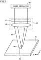
Fig. 2 is a diagram schematically showing a configuration of a laser torch. -
Fig. 3 is a diagram showing an exemplary two-dimensional shape of a laser irradiated region. -
Figs. 4A to 4C each show a distribution of a quantity of heat input in a direction of width of welding. -
Fig. 5 is a diagram showing an exemplary cross-section of a joined portion in fillet welding of a lap joint. -
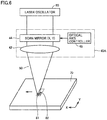
Fig. 6 is a diagram schematically showing a configuration of a laser torch in a second embodiment. -
Fig. 7 is a diagram showing an exemplary two-dimensional shape of a laser irradiated region. - An embodiment of the present disclosure will be described below in detail with reference to the drawings. The same or corresponding elements in the drawings have the same reference characters allotted and description thereof will not be repeated.
-
Fig. 1 is a diagram showing an overall configuration of a laser-arc hybrid welding apparatus according to a first embodiment of the present disclosure. Referring toFig. 1 , a laser-archybrid welding apparatus 1 includes awelding torch 10, aweld wire 20, awelding power supply 30, alaser torch 40, and alaser oscillator 60. - Laser-arc
hybrid welding apparatus 1 is used for joining metals to each other, and can be used particularly for welding in dissimilar material joining. For example, laser-archybrid welding apparatus 1 can be used for welding between an aluminum alloy sheet and a hot-dip galvanized steel sheet such as a GI material or a GA material. Not only soft aluminum but also hard aluminum such as aluminum No. 5000 series (for example, 5052), No. 6000 series (for example, 6063), or No. 7000 series (for example, 7075) defined under JIS can be adopted for the aluminum alloy sheet. With the use of laser-archybrid welding apparatus 1, one and the other of weldedmaterials 70 can be joined to each other, for example, by lap fillet welded joint or flare welded joint. - Welding
torch 10 andwelding power supply 30 are equipment for arc welding. Weldingtorch 10supplies weld wire 20 and not-shown shield gas toward a portion of weldedmaterial 70 to be joined. By receiving supply of a welding current from weldingpower supply 30,welding torch 10 generatesarc 25 between a tip end ofweld wire 20 and the portion of weldedmaterial 70 to be joined and supplies shield gas (argon gas or carbon dioxide) toward a welded portion. Instead ofweld wire 20, an electrode of a non-consumable material (tungsten or the like) may be employed. Arc welding with the use ofwelding torch 10 may be metal arc welding (MAG welding or MIG welding) or non-metal arc welding (TIG welding). - Welding
power supply 30 generates a welding voltage and a welding current for arc welding and outputs the generated welding voltage and welding current to weldingtorch 10. Weldingpower supply 30 controls also a feed rate ofweld wire 20 inwelding torch 10. -
Laser torch 40 andlaser oscillator 60 are equipment for laser welding.Laser torch 40 receives supply of laser beams fromlaser oscillator 60 and emits laser toward the portion of weldedmaterial 70 to be joined. - In laser-arc
hybrid welding apparatus 1 according to the present disclosure,laser torch 40 includes an adjustment mechanism that adjusts a shape of an irradiated region irradiated with laser and a distribution of a laser irradiation energy density in the irradiated region. The adjustment mechanism enlarges the irradiated region in a direction of width of welding as compared with irradiation without the adjustment mechanism. The adjustment mechanism adjusts the shape of the irradiated region and the distribution of the irradiation energy density such that the distribution in the direction of width of welding, of the quantity of heat input (J) by laser exhibits such a profile that the quantity of heat input in the central portion in the width direction is smaller than the quantity of heat input at an end in the width direction. In the present first embodiment, a diffractive optical element (DOE) is provided inlaser torch 40 as such an adjustment mechanism. The configuration oflaser torch 40 will be described later. - By providing such an adjustment mechanism in
laser torch 40, a weld bead of a large width can be formed and joint strength can be secured while the quantity of heat input to the joined portion is suppressed, which will be described in detail below. - As described above, when the quantity of heat input (J) to the joined portion is large, a rate of solidification of a molten weld pool is lowered, which leads to increase in amount of an intermetallic compound generated by welding. For example, in welding between an aluminum alloy sheet and a galvanized steel sheet, an intermetallic compound which is an alloy between aluminum and iron (FeAl, Fe3Al, Fe2Al5, or FeAl3) is generated in a joined portion by welding, and an amount of generation thereof increases with increase in quantity of heat input to the joined portion. Since such an intermetallic compound is more brittle than a parent material, joint strength is lowered with increase in amount of generated intermetallic compound.
- In order to effectively melt a member by increasing an irradiation energy density in an irradiated region, laser is normally adjusted to be focused in the irradiated region. In this case, however, the quantity of heat input to the joined portion increases, which may lead to increase in amount of generated intermetallic compound as described above. Then, joint strength may be lowered.
- In order to suppress the amount of generated intermetallic compound, the quantity of heat input may be suppressed. When the quantity of heat input is suppressed, however, an area of joint between a weld bead and a parent material decreases, which may result in lowering in joint strength. Lowering in joint strength due to decrease in area of joint can be overcome by increasing a width of a weld bead.
- In order to suppress the quantity of heat input, laser may be defocused. Simply by defocusing laser, however, a distribution of the quantity of heat input in the direction of width of welding is such that the quantity of heat input is maximum in a central portion and decreases toward an end because the two-dimensional shape of the laser irradiated region is normally annular. Therefore, in a portion distant from the central portion (for example, an end in the width direction), the quantity of heat input may be insufficient and joint strength may be insufficient.
- In laser-arc
hybrid welding apparatus 1 according to the present first embodiment, the DOE as the adjustment mechanism described above is provided inlaser torch 40. By providing such an adjustment mechanism (DOE), a weld bead of a large width can be formed while the quantity of heat input to the joined portion is suppressed. Consequently, joint strength in the joined portion can be secured. -
Fig. 2 is a diagram schematically showing a configuration oflaser torch 40. Referring toFig. 2 ,laser torch 40 includes aDOE 41 and alens 42. Laser beams output fromlaser oscillator 60 are emitted to weldedmaterial 70 throughDOE 41 andlens 42 so that anirradiated region 80 is formed in weldedmaterial 70. -
DOE 41 processes laser beams received fromlaser oscillator 60 into a desired beam pattern based on a diffraction phenomenon. Specifically,DOE 41 geometrically disperses incident light received fromlaser oscillator 60 and shapes emitted laser such thatirradiated region 80 on weldedmaterial 70 is increased in width as compared with irradiation withoutDOE 41 and is in a substantially rectangular shape. -
Lens 42 condenses laser beams processed byDOE 41 and outputs condensed laser beams toward weldedmaterial 70. -
Fig. 3 is a diagram showing an exemplary two-dimensional shape of irradiatedregion 80. InFig. 3 , a direction of an X axis represents a direction of movement oflaser torch 40 and a direction of a Y axis represents a direction of width of welding. Referring toFig. 3 ,DOE 41 processes laser beams such thatirradiated region 80 is in a substantially rectangular shape. - A group of dotted lines represent a distribution of a laser irradiation energy density. As illustrated, in irradiated
region 80,DOE 41 shapes laser such that the irradiation energy density is higher from center C in the width direction (the direction of the Y axis) toward an end in the width direction. - Though irradiated
region 80 includes opposing sides in parallel to the direction of movement (the direction of the X axis) oflaser torch 40 as short sides and includes opposing sides in parallel to the width direction (the direction of the Y axis) as long sides in this example, irradiatedregion 80 may be in a substantially square shape or include opposing sides in parallel to the direction of movement (the direction of the X axis) oflaser torch 40 as long sides. -
Figs. 4A to 4C each show a distribution of a quantity of heat input in a direction of width of welding.Fig. 4A shows a distribution of a quantity of heat input by laser andFig. 4B shows a distribution of a quantity of heat input by arc.Fig. 4C shows a distribution of the sum of the quantity of heat input by laser and the quantity of heat input by arc. In other words,Fig. 4C shows a distribution of the total quantity of heat input by laser and arc. In each figure, the ordinate represents a quantity of heat input Q and the direction of the Y axis represents the direction of width of welding. Quantity of heat input Q represents a total quantity of heat input (J) from start to end of welding at each point in the width direction. - Referring to
Figs. 4A to 4C , by irradiation with laser to form irradiatedregion 80 shown inFig. 3 , a distribution of the quantity of heat input by laser exhibits such a profile that the quantity of heat input at center C in the width direction is small and increases toward ends as shown inFig. 4A . For a reference purpose, if a two-dimensional shape of a region irradiated with laser is circular, the quantity of heat input would be highly likely to be large at the center in the width direction and smaller toward an end in the width direction in spite of lowering in irradiation energy density in the center of the irradiated region and increase thereof in a peripheral portion. - A distribution of the quantity of heat input by arc exhibits such a profile that the quantity of heat input at center C in the width direction is large and smaller toward the end as shown in
Fig. 4B . Therefore, the heat distribution of the sum of the quantity of heat input by laser and the quantity of heat input by arc is substantially uniform in the width direction as shown inFig. 4C . - In other words, the profile of the quantity of heat input by laser is determined in consideration of the profile of the quantity of heat input by arc such that the profile of the heat distribution of the sum of the quantity of heat input by laser and the quantity of heat input by arc is substantially uniform in the width direction. Based on the profile of the quantity of heat input by laser, the shape of laser irradiated
region 80 and the distribution of the irradiation energy density (the shape and the distribution of the irradiation energy density shown inFig. 3 ) are determined and the configuration ofDOE 41 that realizes such irradiatedregion 80 is determined. - Alternatively,
DOE 41 may be configured to obtain the profile of the quantity of heat input by laser as shown inFig. 4A , and output from weldingtorch 10 may be adjusted by means of welding power supply 30 (controller) such that the profile of the heat distribution of the sum of the quantity of heat input by laser and the quantity of heat input by arc is substantially uniform in the width direction. - Since mechanical characteristics of a welded portion are determined by the quantity of heat input to the welded portion and the heat distribution in each welding process, desired mechanical characteristics in the welded portion can be obtained by adjusting the sum of the quantity of heat input by laser and the quantity of heat input by arc as described above. By making the sum of the quantity of heat input by laser and the quantity of heat input by arc uniform in the width direction, a weld bead high in quality without concentration of a generated intermetallic compound in a part can be formed.
- In particular in welding in dissimilar material joining (for example, welding between an aluminum alloy sheet and a hot-dip galvanized steel sheet), in controlling an amount of a generated intermetallic compound and a distribution thereof, an amount and a distribution of a molten metal should be controlled. In the present embodiment, by adjusting the profile of the quantity of heat input by laser by means of the adjustment mechanism as described above, melting mainly of a parent material can be adjusted and a width of a weld bead as well as a depth (a penetration depth) and a distribution of a molten weld pool can be adjusted. By adjusting output from welding
torch 10 by means ofwelding power supply 30, melting mainly of a weld wire can be adjusted and an amount of a molten metal can be adjusted. -
Fig. 5 is a diagram showing an exemplary cross-section of a joined portion in fillet welding of a lap joint. Referring toFig. 5 , in this example, weldedmaterials 70 include aGI material 71 and analuminum alloy sheet 72 layered onGI material 71. Aweld bead 73 shown with a solid line is a weld bead in fillet welding with the use of laser-archybrid welding apparatus 1 according to the present first embodiment (which may simply be referred to as "welding apparatus 1" below). Aweld bead 75 shown with a dotted line as a comparative example is a weld bead in fillet welding with the use of a laser-arc hybrid welding apparatus without DOE 41 (which is referred to as a "conventional welding apparatus" below). - When welding with the conventional welding apparatus is performed, a laser irradiated region is narrow (when the laser irradiated region is narrow, a width of arc is also narrow) and an irradiation energy density in a central portion of the irradiated region is high. Therefore,
weld bead 75 large in penetration depth into a parent material and narrow inportion 76 of contact with the parent material (GI material 71) is formed. - In contrast, when welding with
welding apparatus 1 is performed, the laser irradiated region is large (when the laser irradiated region is large, a width of arc is also large), the quantity of heat input in the central portion of the irradiated region is suppressed, and the quantity of heat input in the width direction is even. Therefore,weld bead 73 suppressed in penetration depth into a parent material and larger inportion 74 of contact with the parent material thanportion 76 of contact is formed. - Thus, a rate of solidification in generation of
weld bead 73 small in penetration depth into the parent material and large in portion of contact with the parent material is higher than a rate of solidification in generation ofweld bead 75. Therefore, an amount of generated intermetallic compound inweld bead 75 is larger than an amount of generated intermetallic compound inweld bead 73.Portion 74 of contact betweenweld bead 73 and the parent material (GI material 71) is larger thanportion 76 of contact betweenweld bead 75 and the parent material. As set forth above, joint strength achieved byweld bead 73 is higher than joint strength byweld bead 75. - As set forth above, according to the present first embodiment,
DOE 41 capable of forming the laser irradiated region shown inFig. 3 is provided so that the distribution in the width direction of the quantity of heat input exhibits the profile as shown inFigs. 4A to 4C . Therefore, a weld bead of a large width can be formed while the quantity of heat input to the joined portion is suppressed. Consequently, joint strength of the joined portion can be secured. - According to the present first embodiment, by adjusting the distribution (profile) in the width direction, of the sum of the quantity of heat input by laser and the quantity of heat input by arc, desired mechanical characteristics in the welded portion can be obtained. By making the distribution in the width direction of the sum of the quantity of heat input by laser and the quantity of heat input by arc uniform in the width direction, a weld bead high in quality without concentration of a generated intermetallic compound in a part can be formed.
- By adjusting the profile of the quantity of heat input by laser by means of the adjustment mechanism (DOE 41) as above, melting of the parent material can be adjusted and the width of the weld bead as well as the depth (penetration depth) and the distribution of the molten weld pool can be adjusted. By adjusting output from welding
torch 10 by means ofwelding power supply 30, melting of the weld wire can be adjusted. - In the first embodiment, laser irradiated
region 80 as shown withFig. 3 is formed with the use ofDOE 41. In this second embodiment, instead of the DOE, a laser scanning apparatus that can scan weldedmaterial 70 with laser emitted to weldedmaterial 70 is provided in the laser torch and the laser scanning apparatus scans the welded material with laser so that an irradiated region as in the first embodiment is formed. - The laser-arc hybrid welding apparatus in the second embodiment is identical in overall configuration to laser-arc
hybrid welding apparatus 1 shown inFig. 1 . -
Fig. 6 is a diagram schematically showing a configuration of a laser torch in the second embodiment. Referring toFig. 6 , thislaser torch 40A includes ascan mirror 44 and anoptical axis controller 45 instead ofDOE 41 inlaser torch 40 shown inFig. 2 . -
Scan mirror 44 andoptical axis controller 45 correspond to the adjustment mechanism in the present disclosure, and implement the laser scanning apparatus that can scan weldedmaterial 70 with laser.Scan mirror 44 reflects laser beams received fromlaser oscillator 60 and outputs reflected laser beams tolens 42.Scan mirror 44 is variable in its orientation by means ofoptical axis controller 45 and can change aposition 81 of irradiation with laser beams emitted throughlens 42.Scan mirror 44 includes, for example, an X scan mirror that can changeposition 81 of irradiation in an X direction and a Y scan mirror that can changeposition 81 of irradiation in a Y direction. -
Optical axis controller 45 includes a drive apparatus that changes an angle ofscan mirror 44 and a controller that controls the drive apparatus to adjustposition 81 of irradiation with laser beams (neither of which is shown). The drive apparatus is constituted, for example, of an X-axis motor that rotationally drives the X scan mirror and a Y-axis motor that rotationally drives the Y scan mirror. - According to such a configuration, by scanning welded
material 70 with laser, a rectangularirradiated region 82 equivalent to irradiatedregion 80 shown inFig. 3 can be formed on weldedmaterial 70. By adjusting as appropriate output of laser and/or a speed of scanning with laser together with a position of scanning with laser, a profile of an irradiation energy density in irradiatedregion 82 can be adjusted as shown with the dotted lines inFig. 3 . - As set forth above, according to this second embodiment as well, an effect as in the first embodiment is obtained. According to this second embodiment, irradiated
region 82 having a shape and a distribution of an irradiation energy density as desired is formed by usingscan mirror 44 andoptical axis controller 45, and hence a degree of freedom in forming desiredirradiated region 82 is high. - In the first embodiment, laser irradiated
region 80 as shown inFig. 3 is formed with the use ofDOE 41. Specifically, the two-dimensional shape of irradiatedregion 80 is rectangular andirradiated region 80 has such a distribution of the irradiation energy density that the irradiation energy density is higher from the center in the width direction toward an end in the width direction. -
Irradiated region 80 formed byDOE 41, however, is not limited to the irradiated region with the shape and the distribution of the irradiation energy density as such. For example, as shown inFig. 7 , irradiatedregion 80 may have a length along the direction of progress of welding (the direction of the X axis) at center C in the width direction (the direction of the Y axis) shorter than a length at an end in the width direction and may have a substantially uniform irradiation energy density in the width direction. - With irradiated
region 80 having the shape and the distribution of the irradiation energy density as such as well, the profile of the quantity of heat input by laser as shown inFig. 4A is obtained. Therefore, an effect as in the first embodiment is obtained. - In the second embodiment as well, irradiated
region 82 having the shape and the distribution of the irradiation energy density as shown inFig. 7 may be formed with the use oflaser torch 40A. - In each embodiment and the modification above, the profile of the quantity of heat input by laser is determined or output from welding
torch 10 is adjusted by means ofwelding power supply 30 such that the profile of the sum of the quantity of heat input by laser and the quantity of heat input by arc is substantially uniform in the width direction. The profile in the width direction of the sum of the quantity of heat input by laser and the quantity of heat input by arc, however, is not limited as such. The profile of the sum of the quantity of heat input by laser and the quantity of heat input by arc may exhibit such a prescribed profile that the quantity of heat input in the central portion in the width direction is larger than the quantity of heat input at the end in the width direction to such an extent that the quantity of heat input in the central portion is not too large, or that the quantity of heat input in the central portion is smaller than the quantity of heat input at the end. - In each embodiment and the modification above, the profile of the quantity of heat input by laser is such that the quantity of heat input is small in the center in the width direction as shown in
Fig. 4A . The quantity of heat input by laser, however, may substantially be uniform in the width direction. In this case, in the profile of the sum of the quantity of heat input by laser and the quantity of heat input by arc, the quantity of heat input in the central portion is larger than the quantity of heat input at the end, however, the quantity of heat input in the central portion can be suppressed and the distribution of the quantity of heat input can be enlarged in the width direction as compared with an example where the profile of the quantity of heat input by laser is not adjusted. - It should be understood that the embodiments disclosed herein are illustrative and non-restrictive in every respect. The scope of the present invention is defined by the terms of the claims and is intended to include any modifications within the scope and meaning equivalent to the terms of the claims.
Claims (7)
- A laser-arc hybrid welding apparatus (1) that uses laser and arc, the laser-arc hybrid welding apparatus comprising:a laser torch (40; 40A) that emits laser toward a joined portion; anda welding torch (10) that generates arc between the welding torch and the joined portion,the laser torch including an adjustment mechanism (41; 44, 45) that adjusts a shape of an irradiated region (80) irradiated with laser,the adjustment mechanism enlarging the irradiated region in a direction of width of welding as compared with irradiation without the adjustment mechanism in the laser torch and adjusting a shape of the irradiated region to allow a distribution in the direction of width, of a quantity of heat input by laser to exhibit a prescribed profile,the prescribed profile being such a profile that the quantity of heat input in a central portion in the direction of width is equal to or smaller than the quantity of heat input at an end in the direction of width.
- The laser-arc hybrid welding apparatus according to claim 1, wherein
the adjustment mechanism adjusts the shape of the irradiated region to a rectangular shape including opposing sides in parallel to a direction of movement of the laser torch. - The laser-arc hybrid welding apparatus according to claim 2, wherein
the adjustment mechanism further adjusts a distribution of a laser irradiation energy density in the irradiated region to set the irradiation energy density in the central portion in the direction of width to be lower than the irradiation energy density at the end in the direction of width. - The laser-arc hybrid welding apparatus according to claim 1, wherein
the adjustment mechanism adjusts the shape of the irradiated region to set a length of the irradiated region along a direction of movement of the laser torch in the central portion in the direction of width to be shorter than a length of the irradiated region along the direction of movement at the end in the direction of width. - The laser-arc hybrid welding apparatus according to any one of claims 1 to 4, wherein
a distribution in the direction of width, of a sum of the quantity of heat input by laser and a quantity of heat input by arc exhibits a prescribed heat distribution. - The laser-arc hybrid welding apparatus according to claim 5, further comprising a controller (30) that adjusts output from the welding torch, wherein
at least one of adjustment of the shape of the irradiated region by the adjustment mechanism and adjustment of the output from the welding torch by the controller is made to allow the distribution in the direction of width, of the sum of the quantity of heat input by laser and the quantity of heat input by arc to exhibit the prescribed heat distribution. - The laser-arc hybrid welding apparatus according to claim 5 or 6, wherein
the prescribed profile is such a profile that the quantity of heat input in the central portion in the direction of width is smaller than the quantity of heat input at the end in the direction of width, and
the prescribed heat distribution is uniform in the direction of width.
Applications Claiming Priority (1)
| Application Number | Priority Date | Filing Date | Title |
|---|---|---|---|
| JP2019128190A JP7284014B2 (en) | 2019-07-10 | 2019-07-10 | Laser-arc hybrid welding equipment |
Publications (3)
| Publication Number | Publication Date |
|---|---|
| EP3785843A2 true EP3785843A2 (en) | 2021-03-03 |
| EP3785843A3 EP3785843A3 (en) | 2021-03-24 |
| EP3785843B1 EP3785843B1 (en) | 2023-01-04 |
Family
ID=71465104
Family Applications (1)
| Application Number | Title | Priority Date | Filing Date |
|---|---|---|---|
| EP20183786.1A Active EP3785843B1 (en) | 2019-07-10 | 2020-07-02 | Laser-arc hybrid welding apparatus |
Country Status (4)
| Country | Link |
|---|---|
| US (1) | US20210008666A1 (en) |
| EP (1) | EP3785843B1 (en) |
| JP (1) | JP7284014B2 (en) |
| CN (1) | CN112207443B (en) |
Families Citing this family (2)
| Publication number | Priority date | Publication date | Assignee | Title |
|---|---|---|---|---|
| CN114131200B (en) * | 2021-11-26 | 2022-08-02 | 华中科技大学 | Process control method, system and device for laser-arc hybrid welding |
| CN119387855B (en) * | 2024-12-05 | 2026-04-14 | 中车株洲车辆有限公司 | Steel welding method, steel product and application thereof |
Citations (1)
| Publication number | Priority date | Publication date | Assignee | Title |
|---|---|---|---|---|
| JP2005040806A (en) | 2003-07-24 | 2005-02-17 | Daihen Corp | Laser irradiation arc welding method for galvanized steel sheet |
Family Cites Families (47)
| Publication number | Priority date | Publication date | Assignee | Title |
|---|---|---|---|---|
| US4532404A (en) * | 1983-02-01 | 1985-07-30 | Canadian Patents And Development Limited | Real time control system and process for controlling predetermined operating characteristics of a welding mechanism |
| US5552575A (en) * | 1994-07-15 | 1996-09-03 | Tufts University | Scan welding method and apparatus |
| DE4446560C1 (en) * | 1994-12-24 | 1996-08-01 | Fraunhofer Ges Forschung | Process for welding workpieces with laser radiation |
| US6191379B1 (en) * | 1999-04-05 | 2001-02-20 | General Electric Company | Heat treatment for weld beads |
| TW552645B (en) * | 2001-08-03 | 2003-09-11 | Semiconductor Energy Lab | Laser irradiating device, laser irradiating method and manufacturing method of semiconductor device |
| JP3762676B2 (en) * | 2001-09-17 | 2006-04-05 | 本田技研工業株式会社 | Work welding method |
| FR2832337B1 (en) * | 2001-11-22 | 2004-01-23 | Commissariat Energie Atomique | HYBRID WELDING DEVICE AND METHOD |
| JP2004001084A (en) * | 2002-03-28 | 2004-01-08 | Ishikawajima Harima Heavy Ind Co Ltd | Twin spot laser welding method and apparatus |
| US7154065B2 (en) * | 2002-05-24 | 2006-12-26 | Alcon Inc. | Laser-hybrid welding with beam oscillation |
| US6906281B2 (en) * | 2003-03-03 | 2005-06-14 | Dana Corporation | Method for laser welding of metal |
| AT413667B (en) * | 2004-05-10 | 2006-04-15 | Fronius Int Gmbh | WELDING PROCESS AND LASER HYBRID WELDING BURNER |
| KR100656682B1 (en) * | 2005-12-26 | 2006-12-13 | 한국생산기술연구원 | Laser-arc arc hybrid welding device and welding method using the same |
| WO2007094442A1 (en) * | 2006-02-17 | 2007-08-23 | Taiyo Nippon Sanso Corporation | Shield gas for hybrid welding and method of hybrid welding using the gas |
| JP5398165B2 (en) * | 2008-04-24 | 2014-01-29 | 三菱重工業株式会社 | Laser / arc combined welding head and method thereof |
| WO2010021094A1 (en) * | 2008-08-19 | 2010-02-25 | パナソニック株式会社 | Composite welding method and composite welding device |
| US20100288738A1 (en) * | 2009-05-15 | 2010-11-18 | General Electric Company | Welding apparatus and method |
| WO2011118172A1 (en) * | 2010-03-24 | 2011-09-29 | パナソニック株式会社 | Laser welding method and laser welding apparatus |
| US8253060B2 (en) * | 2010-06-30 | 2012-08-28 | General Electric Company | Hybrid laser arc welding process and apparatus |
| US8253061B2 (en) * | 2010-07-07 | 2012-08-28 | General Electric Company | Hybrid laser arc welding process and apparatus |
| US8546720B2 (en) * | 2011-04-13 | 2013-10-01 | General Electric Company | Hybrid welding apparatus and system and method of welding |
| DE202011100178U1 (en) * | 2011-04-29 | 2012-07-31 | 3D-Micromac Ag | Device for direct energy coupling into organic semiconductor material for solar cells |
| US10384293B2 (en) * | 2011-04-29 | 2019-08-20 | Lincoln Global, Inc. | Method and apparatus for heavy plate joining with hybrid laser and submerged-arc welding process |
| US9180553B2 (en) * | 2011-09-29 | 2015-11-10 | Lincoln Global, Inc. | Electrode for GMAW hybrid laser arc welding |
| US8766140B2 (en) * | 2011-10-06 | 2014-07-01 | Lincoln Global, Inc. | Apparatus and method for laser cleaning of coated materials prior to welding |
| US10201877B2 (en) * | 2011-10-26 | 2019-02-12 | Titanova Inc | Puddle forming and shaping with primary and secondary lasers |
| US8853594B2 (en) * | 2012-07-09 | 2014-10-07 | General Electric Company | Welding method and apparatus therefor |
| US9221118B2 (en) * | 2012-07-26 | 2015-12-29 | General Electric Company | Adaptive control hybrid welding system and methods of controlling |
| US20140027414A1 (en) * | 2012-07-26 | 2014-01-30 | General Electric Company | Hybrid welding system and method of welding |
| US8941031B2 (en) * | 2012-08-22 | 2015-01-27 | Caterpillar Inc. | Systems and methods for dual-weave welding |
| MX381438B (en) * | 2012-11-30 | 2025-03-04 | Twb Company Llc | METHOD FOR FORMING A WELD NOTCH IN A PIECE OF SHEET METAL. |
| US20140263191A1 (en) * | 2013-03-15 | 2014-09-18 | Lincoln Global, Inc. | System and method of welding stainless steel to copper |
| US10328513B2 (en) * | 2013-05-31 | 2019-06-25 | General Electric Company | Welding process, welding system, and welded article |
| US10981248B2 (en) * | 2013-11-22 | 2021-04-20 | General Electric Company | Hybrid welding apparatuses, systems and methods for spatially offset components |
| US9718147B2 (en) * | 2014-03-07 | 2017-08-01 | Lincoln Global, Inc. | Method and system to start and use combination filler wire feed and high intensity energy source for root pass welding of the inner diameter of clad pipe |
| US9925715B2 (en) * | 2014-06-30 | 2018-03-27 | General Electric Company | Systems and methods for monitoring a melt pool using a dedicated scanning device |
| JP2016043391A (en) * | 2014-08-25 | 2016-04-04 | 株式会社Ihi | Laser arc hybrid welding method |
| DE102014116958B9 (en) * | 2014-11-19 | 2017-10-05 | Trumpf Laser- Und Systemtechnik Gmbh | Optical system for beam shaping of a laser beam, laser processing system, method for material processing and use of a common elongated focus zone for laser material processing |
| DE102015104411B4 (en) * | 2015-03-24 | 2017-02-16 | Scansonic Mi Gmbh | Laser beam joining process and laser processing optics |
| JP6494452B2 (en) * | 2015-07-08 | 2019-04-03 | 日立オートモティブシステムズ株式会社 | Laser welding method, high-pressure fuel supply pump and fuel injection valve |
| CN105945430B (en) * | 2016-05-30 | 2017-07-07 | 重庆理工大学 | A kind of low power laser high-efficiency welding method based on micro-beam plasma arc induction |
| US10799986B2 (en) * | 2016-06-27 | 2020-10-13 | Illinois Tool Works Inc. | Wide path welding, cladding, additive manufacturing |
| US11919103B2 (en) * | 2016-07-22 | 2024-03-05 | Illinois Tool Works Inc. | Laser welding, cladding, and/or additive manufacturing systems and methods of laser welding, cladding, and/or additive manufacturing |
| DE102016116124A1 (en) * | 2016-08-30 | 2018-03-01 | Kuka Industries Gmbh & Co. Kg | Method and device for welding joining partners |
| CN106735909A (en) * | 2017-02-07 | 2017-05-31 | 王长春 | It is a kind of for laser beam and the welding torch of plasma arc composite welding |
| US10870177B2 (en) * | 2017-06-22 | 2020-12-22 | Esab Ab | Modular welding head assembly |
| JP6525116B1 (en) * | 2017-09-20 | 2019-06-05 | Jfeスチール株式会社 | Laser arc hybrid welding method |
| CN109530920A (en) * | 2018-11-30 | 2019-03-29 | 东北大学 | A kind of Hi-grade steel pipe line steel laser-MAG compound welding method |
-
2019
- 2019-07-10 JP JP2019128190A patent/JP7284014B2/en active Active
-
2020
- 2020-07-02 EP EP20183786.1A patent/EP3785843B1/en active Active
- 2020-07-06 CN CN202010639862.4A patent/CN112207443B/en active Active
- 2020-07-09 US US16/925,075 patent/US20210008666A1/en active Pending
Patent Citations (1)
| Publication number | Priority date | Publication date | Assignee | Title |
|---|---|---|---|---|
| JP2005040806A (en) | 2003-07-24 | 2005-02-17 | Daihen Corp | Laser irradiation arc welding method for galvanized steel sheet |
Also Published As
| Publication number | Publication date |
|---|---|
| CN112207443B (en) | 2025-02-11 |
| EP3785843B1 (en) | 2023-01-04 |
| CN112207443A (en) | 2021-01-12 |
| US20210008666A1 (en) | 2021-01-14 |
| EP3785843A3 (en) | 2021-03-24 |
| JP7284014B2 (en) | 2023-05-30 |
| JP2021013932A (en) | 2021-02-12 |
Similar Documents
| Publication | Publication Date | Title |
|---|---|---|
| US7015417B2 (en) | Workpiece welding process | |
| EP2744619B1 (en) | Method to start and use combination filler wire feed and high intensity energy source for welding | |
| JP5941252B2 (en) | Hybrid laser arc welding process and apparatus | |
| JP3201246U (en) | System for initiating and using a combination of filler wire feeder and high strength energy source for welding | |
| EP3785843B1 (en) | Laser-arc hybrid welding apparatus | |
| JP5318543B2 (en) | Laser-arc combined welding method | |
| JP5812527B2 (en) | Hot wire laser welding method and apparatus | |
| JP7416999B2 (en) | Laser-arc hybrid welding equipment | |
| JP2022025953A (en) | Laser/arc hybrid welding apparatus | |
| JP7305502B2 (en) | Laser-arc hybrid welding equipment | |
| JP3591630B2 (en) | Laser-arc combined welding method and welding apparatus | |
| JP7428596B2 (en) | Laser-arc hybrid welding equipment | |
| EP3922396A1 (en) | Laser-arc hybrid welding apparatus | |
| JP7219195B2 (en) | Laser-arc hybrid welding equipment | |
| JP2007090397A (en) | Lap fillet welding method | |
| JP2005040806A (en) | Laser irradiation arc welding method for galvanized steel sheet | |
| JP2004195528A (en) | Laser irradiation arc welding method of magnesium or magnesium alloy | |
| JP5489005B2 (en) | Welding method | |
| JP7791501B1 (en) | Manufacturing method for steel plate welded joints | |
| JP2021186828A (en) | Laser / arc hybrid welding equipment | |
| Katayama | Characteristic Welding Processes | |
| JPH11300485A (en) | Laser welding method of aluminum alloy material using aluminum alloy filler metal |
Legal Events
| Date | Code | Title | Description |
|---|---|---|---|
| PUAI | Public reference made under article 153(3) epc to a published international application that has entered the european phase |
Free format text: ORIGINAL CODE: 0009012 |
|
| STAA | Information on the status of an ep patent application or granted ep patent |
Free format text: STATUS: REQUEST FOR EXAMINATION WAS MADE |
|
| PUAL | Search report despatched |
Free format text: ORIGINAL CODE: 0009013 |
|
| 17P | Request for examination filed |
Effective date: 20200702 |
|
| AK | Designated contracting states |
Kind code of ref document: A2 Designated state(s): AL AT BE BG CH CY CZ DE DK EE ES FI FR GB GR HR HU IE IS IT LI LT LU LV MC MK MT NL NO PL PT RO RS SE SI SK SM TR |
|
| AX | Request for extension of the european patent |
Extension state: BA ME |
|
| AK | Designated contracting states |
Kind code of ref document: A3 Designated state(s): AL AT BE BG CH CY CZ DE DK EE ES FI FR GB GR HR HU IE IS IT LI LT LU LV MC MK MT NL NO PL PT RO RS SE SI SK SM TR |
|
| AX | Request for extension of the european patent |
Extension state: BA ME |
|
| RIC1 | Information provided on ipc code assigned before grant |
Ipc: B23K 26/346 20140101AFI20210217BHEP Ipc: B23K 26/073 20060101ALI20210217BHEP Ipc: B23K 26/348 20140101ALI20210217BHEP Ipc: B23K 26/244 20140101ALI20210217BHEP Ipc: B23K 26/082 20140101ALI20210217BHEP Ipc: B23K 26/352 20140101ALI20210217BHEP |
|
| RBV | Designated contracting states (corrected) |
Designated state(s): AL AT BE BG CH CY CZ DE DK EE ES FI FR GB GR HR HU IE IS IT LI LT LU LV MC MK MT NL NO PL PT RO RS SE SI SK SM TR |
|
| GRAP | Despatch of communication of intention to grant a patent |
Free format text: ORIGINAL CODE: EPIDOSNIGR1 |
|
| STAA | Information on the status of an ep patent application or granted ep patent |
Free format text: STATUS: GRANT OF PATENT IS INTENDED |
|
| INTG | Intention to grant announced |
Effective date: 20220831 |
|
| GRAS | Grant fee paid |
Free format text: ORIGINAL CODE: EPIDOSNIGR3 |
|
| GRAA | (expected) grant |
Free format text: ORIGINAL CODE: 0009210 |
|
| STAA | Information on the status of an ep patent application or granted ep patent |
Free format text: STATUS: THE PATENT HAS BEEN GRANTED |
|
| AK | Designated contracting states |
Kind code of ref document: B1 Designated state(s): AL AT BE BG CH CY CZ DE DK EE ES FI FR GB GR HR HU IE IS IT LI LT LU LV MC MK MT NL NO PL PT RO RS SE SI SK SM TR |
|
| REG | Reference to a national code |
Ref country code: GB Ref legal event code: FG4D |
|
| REG | Reference to a national code |
Ref country code: DE Ref legal event code: R096 Ref document number: 602020007305 Country of ref document: DE |
|
| REG | Reference to a national code |
Ref country code: CH Ref legal event code: EP |
|
| REG | Reference to a national code |
Ref country code: AT Ref legal event code: REF Ref document number: 1541585 Country of ref document: AT Kind code of ref document: T Effective date: 20230115 |
|
| REG | Reference to a national code |
Ref country code: IE Ref legal event code: FG4D |
|
| REG | Reference to a national code |
Ref country code: LT Ref legal event code: MG9D |
|
| REG | Reference to a national code |
Ref country code: NL Ref legal event code: MP Effective date: 20230104 |
|
| REG | Reference to a national code |
Ref country code: AT Ref legal event code: MK05 Ref document number: 1541585 Country of ref document: AT Kind code of ref document: T Effective date: 20230104 |
|
| PG25 | Lapsed in a contracting state [announced via postgrant information from national office to epo] |
Ref country code: NL Free format text: LAPSE BECAUSE OF FAILURE TO SUBMIT A TRANSLATION OF THE DESCRIPTION OR TO PAY THE FEE WITHIN THE PRESCRIBED TIME-LIMIT Effective date: 20230104 |
|
| PG25 | Lapsed in a contracting state [announced via postgrant information from national office to epo] |
Ref country code: RS Free format text: LAPSE BECAUSE OF FAILURE TO SUBMIT A TRANSLATION OF THE DESCRIPTION OR TO PAY THE FEE WITHIN THE PRESCRIBED TIME-LIMIT Effective date: 20230104 Ref country code: PT Free format text: LAPSE BECAUSE OF FAILURE TO SUBMIT A TRANSLATION OF THE DESCRIPTION OR TO PAY THE FEE WITHIN THE PRESCRIBED TIME-LIMIT Effective date: 20230504 Ref country code: NO Free format text: LAPSE BECAUSE OF FAILURE TO SUBMIT A TRANSLATION OF THE DESCRIPTION OR TO PAY THE FEE WITHIN THE PRESCRIBED TIME-LIMIT Effective date: 20230404 Ref country code: LV Free format text: LAPSE BECAUSE OF FAILURE TO SUBMIT A TRANSLATION OF THE DESCRIPTION OR TO PAY THE FEE WITHIN THE PRESCRIBED TIME-LIMIT Effective date: 20230104 Ref country code: LT Free format text: LAPSE BECAUSE OF FAILURE TO SUBMIT A TRANSLATION OF THE DESCRIPTION OR TO PAY THE FEE WITHIN THE PRESCRIBED TIME-LIMIT Effective date: 20230104 Ref country code: HR Free format text: LAPSE BECAUSE OF FAILURE TO SUBMIT A TRANSLATION OF THE DESCRIPTION OR TO PAY THE FEE WITHIN THE PRESCRIBED TIME-LIMIT Effective date: 20230104 Ref country code: ES Free format text: LAPSE BECAUSE OF FAILURE TO SUBMIT A TRANSLATION OF THE DESCRIPTION OR TO PAY THE FEE WITHIN THE PRESCRIBED TIME-LIMIT Effective date: 20230104 Ref country code: AT Free format text: LAPSE BECAUSE OF FAILURE TO SUBMIT A TRANSLATION OF THE DESCRIPTION OR TO PAY THE FEE WITHIN THE PRESCRIBED TIME-LIMIT Effective date: 20230104 |
|
| PG25 | Lapsed in a contracting state [announced via postgrant information from national office to epo] |
Ref country code: SE Free format text: LAPSE BECAUSE OF FAILURE TO SUBMIT A TRANSLATION OF THE DESCRIPTION OR TO PAY THE FEE WITHIN THE PRESCRIBED TIME-LIMIT Effective date: 20230104 Ref country code: PL Free format text: LAPSE BECAUSE OF FAILURE TO SUBMIT A TRANSLATION OF THE DESCRIPTION OR TO PAY THE FEE WITHIN THE PRESCRIBED TIME-LIMIT Effective date: 20230104 Ref country code: IS Free format text: LAPSE BECAUSE OF FAILURE TO SUBMIT A TRANSLATION OF THE DESCRIPTION OR TO PAY THE FEE WITHIN THE PRESCRIBED TIME-LIMIT Effective date: 20230504 Ref country code: GR Free format text: LAPSE BECAUSE OF FAILURE TO SUBMIT A TRANSLATION OF THE DESCRIPTION OR TO PAY THE FEE WITHIN THE PRESCRIBED TIME-LIMIT Effective date: 20230405 Ref country code: FI Free format text: LAPSE BECAUSE OF FAILURE TO SUBMIT A TRANSLATION OF THE DESCRIPTION OR TO PAY THE FEE WITHIN THE PRESCRIBED TIME-LIMIT Effective date: 20230104 |
|
| REG | Reference to a national code |
Ref country code: DE Ref legal event code: R097 Ref document number: 602020007305 Country of ref document: DE |
|
| PG25 | Lapsed in a contracting state [announced via postgrant information from national office to epo] |
Ref country code: SM Free format text: LAPSE BECAUSE OF FAILURE TO SUBMIT A TRANSLATION OF THE DESCRIPTION OR TO PAY THE FEE WITHIN THE PRESCRIBED TIME-LIMIT Effective date: 20230104 Ref country code: RO Free format text: LAPSE BECAUSE OF FAILURE TO SUBMIT A TRANSLATION OF THE DESCRIPTION OR TO PAY THE FEE WITHIN THE PRESCRIBED TIME-LIMIT Effective date: 20230104 Ref country code: EE Free format text: LAPSE BECAUSE OF FAILURE TO SUBMIT A TRANSLATION OF THE DESCRIPTION OR TO PAY THE FEE WITHIN THE PRESCRIBED TIME-LIMIT Effective date: 20230104 Ref country code: DK Free format text: LAPSE BECAUSE OF FAILURE TO SUBMIT A TRANSLATION OF THE DESCRIPTION OR TO PAY THE FEE WITHIN THE PRESCRIBED TIME-LIMIT Effective date: 20230104 Ref country code: CZ Free format text: LAPSE BECAUSE OF FAILURE TO SUBMIT A TRANSLATION OF THE DESCRIPTION OR TO PAY THE FEE WITHIN THE PRESCRIBED TIME-LIMIT Effective date: 20230104 |
|
| PGFP | Annual fee paid to national office [announced via postgrant information from national office to epo] |
Ref country code: IT Payment date: 20230731 Year of fee payment: 4 |
|
| PLBE | No opposition filed within time limit |
Free format text: ORIGINAL CODE: 0009261 |
|
| STAA | Information on the status of an ep patent application or granted ep patent |
Free format text: STATUS: NO OPPOSITION FILED WITHIN TIME LIMIT |
|
| PG25 | Lapsed in a contracting state [announced via postgrant information from national office to epo] |
Ref country code: SK Free format text: LAPSE BECAUSE OF FAILURE TO SUBMIT A TRANSLATION OF THE DESCRIPTION OR TO PAY THE FEE WITHIN THE PRESCRIBED TIME-LIMIT Effective date: 20230104 |
|
| PGFP | Annual fee paid to national office [announced via postgrant information from national office to epo] |
Ref country code: FR Payment date: 20230717 Year of fee payment: 4 Ref country code: DE Payment date: 20230620 Year of fee payment: 4 |
|
| 26N | No opposition filed |
Effective date: 20231005 |
|
| PG25 | Lapsed in a contracting state [announced via postgrant information from national office to epo] |
Ref country code: SI Free format text: LAPSE BECAUSE OF FAILURE TO SUBMIT A TRANSLATION OF THE DESCRIPTION OR TO PAY THE FEE WITHIN THE PRESCRIBED TIME-LIMIT Effective date: 20230104 |
|
| PG25 | Lapsed in a contracting state [announced via postgrant information from national office to epo] |
Ref country code: MC Free format text: LAPSE BECAUSE OF FAILURE TO SUBMIT A TRANSLATION OF THE DESCRIPTION OR TO PAY THE FEE WITHIN THE PRESCRIBED TIME-LIMIT Effective date: 20230104 |
|
| PG25 | Lapsed in a contracting state [announced via postgrant information from national office to epo] |
Ref country code: MC Free format text: LAPSE BECAUSE OF FAILURE TO SUBMIT A TRANSLATION OF THE DESCRIPTION OR TO PAY THE FEE WITHIN THE PRESCRIBED TIME-LIMIT Effective date: 20230104 |
|
| REG | Reference to a national code |
Ref country code: CH Ref legal event code: PL |
|
| REG | Reference to a national code |
Ref country code: BE Ref legal event code: MM Effective date: 20230731 |
|
| PG25 | Lapsed in a contracting state [announced via postgrant information from national office to epo] |
Ref country code: LU Free format text: LAPSE BECAUSE OF NON-PAYMENT OF DUE FEES Effective date: 20230702 |
|
| PG25 | Lapsed in a contracting state [announced via postgrant information from national office to epo] |
Ref country code: LU Free format text: LAPSE BECAUSE OF NON-PAYMENT OF DUE FEES Effective date: 20230702 |
|
| REG | Reference to a national code |
Ref country code: IE Ref legal event code: MM4A |
|
| PG25 | Lapsed in a contracting state [announced via postgrant information from national office to epo] |
Ref country code: CH Free format text: LAPSE BECAUSE OF NON-PAYMENT OF DUE FEES Effective date: 20230731 |
|
| PG25 | Lapsed in a contracting state [announced via postgrant information from national office to epo] |
Ref country code: BE Free format text: LAPSE BECAUSE OF NON-PAYMENT OF DUE FEES Effective date: 20230731 |
|
| PG25 | Lapsed in a contracting state [announced via postgrant information from national office to epo] |
Ref country code: IE Free format text: LAPSE BECAUSE OF NON-PAYMENT OF DUE FEES Effective date: 20230702 |
|
| PG25 | Lapsed in a contracting state [announced via postgrant information from national office to epo] |
Ref country code: IE Free format text: LAPSE BECAUSE OF NON-PAYMENT OF DUE FEES Effective date: 20230702 |
|
| PG25 | Lapsed in a contracting state [announced via postgrant information from national office to epo] |
Ref country code: BG Free format text: LAPSE BECAUSE OF FAILURE TO SUBMIT A TRANSLATION OF THE DESCRIPTION OR TO PAY THE FEE WITHIN THE PRESCRIBED TIME-LIMIT Effective date: 20230104 |
|
| PG25 | Lapsed in a contracting state [announced via postgrant information from national office to epo] |
Ref country code: BG Free format text: LAPSE BECAUSE OF FAILURE TO SUBMIT A TRANSLATION OF THE DESCRIPTION OR TO PAY THE FEE WITHIN THE PRESCRIBED TIME-LIMIT Effective date: 20230104 |
|
| REG | Reference to a national code |
Ref country code: DE Ref legal event code: R119 Ref document number: 602020007305 Country of ref document: DE |
|
| GBPC | Gb: european patent ceased through non-payment of renewal fee |
Effective date: 20240702 |
|
| PG25 | Lapsed in a contracting state [announced via postgrant information from national office to epo] |
Ref country code: DE Free format text: LAPSE BECAUSE OF NON-PAYMENT OF DUE FEES Effective date: 20250201 |
|
| PG25 | Lapsed in a contracting state [announced via postgrant information from national office to epo] |
Ref country code: FR Free format text: LAPSE BECAUSE OF NON-PAYMENT OF DUE FEES Effective date: 20240731 |
|
| PG25 | Lapsed in a contracting state [announced via postgrant information from national office to epo] |
Ref country code: GB Free format text: LAPSE BECAUSE OF NON-PAYMENT OF DUE FEES Effective date: 20240702 |
|
| PG25 | Lapsed in a contracting state [announced via postgrant information from national office to epo] |
Ref country code: IT Free format text: LAPSE BECAUSE OF NON-PAYMENT OF DUE FEES Effective date: 20240702 |
|
| PG25 | Lapsed in a contracting state [announced via postgrant information from national office to epo] |
Ref country code: CY Free format text: LAPSE BECAUSE OF FAILURE TO SUBMIT A TRANSLATION OF THE DESCRIPTION OR TO PAY THE FEE WITHIN THE PRESCRIBED TIME-LIMIT; INVALID AB INITIO Effective date: 20200702 |
|
| PG25 | Lapsed in a contracting state [announced via postgrant information from national office to epo] |
Ref country code: HU Free format text: LAPSE BECAUSE OF FAILURE TO SUBMIT A TRANSLATION OF THE DESCRIPTION OR TO PAY THE FEE WITHIN THE PRESCRIBED TIME-LIMIT; INVALID AB INITIO Effective date: 20200702 |
|
| PG25 | Lapsed in a contracting state [announced via postgrant information from national office to epo] |
Ref country code: TR Free format text: LAPSE BECAUSE OF FAILURE TO SUBMIT A TRANSLATION OF THE DESCRIPTION OR TO PAY THE FEE WITHIN THE PRESCRIBED TIME-LIMIT Effective date: 20230104 |