EP3784955B1 - Assemblies, systems and methods for balanced suspension of luminaires - Google Patents
Assemblies, systems and methods for balanced suspension of luminaires Download PDFInfo
- Publication number
- EP3784955B1 EP3784955B1 EP19791817.0A EP19791817A EP3784955B1 EP 3784955 B1 EP3784955 B1 EP 3784955B1 EP 19791817 A EP19791817 A EP 19791817A EP 3784955 B1 EP3784955 B1 EP 3784955B1
- Authority
- EP
- European Patent Office
- Prior art keywords
- yoke
- suspension
- housing
- assembly
- luminaire
- Prior art date
- Legal status (The legal status is an assumption and is not a legal conclusion. Google has not performed a legal analysis and makes no representation as to the accuracy of the status listed.)
- Active
Links
Images

Classifications
-
- F—MECHANICAL ENGINEERING; LIGHTING; HEATING; WEAPONS; BLASTING
- F21—LIGHTING
- F21V—FUNCTIONAL FEATURES OR DETAILS OF LIGHTING DEVICES OR SYSTEMS THEREOF; STRUCTURAL COMBINATIONS OF LIGHTING DEVICES WITH OTHER ARTICLES, NOT OTHERWISE PROVIDED FOR
- F21V21/00—Supporting, suspending, or attaching arrangements for lighting devices; Hand grips
- F21V21/02—Wall, ceiling, or floor bases; Fixing pendants or arms to the bases
-
- F—MECHANICAL ENGINEERING; LIGHTING; HEATING; WEAPONS; BLASTING
- F21—LIGHTING
- F21V—FUNCTIONAL FEATURES OR DETAILS OF LIGHTING DEVICES OR SYSTEMS THEREOF; STRUCTURAL COMBINATIONS OF LIGHTING DEVICES WITH OTHER ARTICLES, NOT OTHERWISE PROVIDED FOR
- F21V21/00—Supporting, suspending, or attaching arrangements for lighting devices; Hand grips
- F21V21/14—Adjustable mountings
- F21V21/16—Adjustable mountings using wires or cords
-
- F—MECHANICAL ENGINEERING; LIGHTING; HEATING; WEAPONS; BLASTING
- F16—ENGINEERING ELEMENTS AND UNITS; GENERAL MEASURES FOR PRODUCING AND MAINTAINING EFFECTIVE FUNCTIONING OF MACHINES OR INSTALLATIONS; THERMAL INSULATION IN GENERAL
- F16M—FRAMES, CASINGS OR BEDS OF ENGINES, MACHINES OR APPARATUS, NOT SPECIFIC TO ENGINES, MACHINES OR APPARATUS PROVIDED FOR ELSEWHERE; STANDS; SUPPORTS
- F16M13/00—Other supports for positioning apparatus or articles; Means for steadying hand-held apparatus or articles
- F16M13/02—Other supports for positioning apparatus or articles; Means for steadying hand-held apparatus or articles for supporting on, or attaching to, an object, e.g. tree, gate, window-frame, cycle
- F16M13/022—Other supports for positioning apparatus or articles; Means for steadying hand-held apparatus or articles for supporting on, or attaching to, an object, e.g. tree, gate, window-frame, cycle repositionable
-
- F—MECHANICAL ENGINEERING; LIGHTING; HEATING; WEAPONS; BLASTING
- F21—LIGHTING
- F21S—NON-PORTABLE LIGHTING DEVICES; SYSTEMS THEREOF; VEHICLE LIGHTING DEVICES SPECIALLY ADAPTED FOR VEHICLE EXTERIORS
- F21S8/00—Lighting devices intended for fixed installation
- F21S8/04—Lighting devices intended for fixed installation intended only for mounting on a ceiling or the like overhead structures
- F21S8/06—Lighting devices intended for fixed installation intended only for mounting on a ceiling or the like overhead structures by suspension
- F21S8/061—Lighting devices intended for fixed installation intended only for mounting on a ceiling or the like overhead structures by suspension with a non-rigid pendant, i.e. a cable, wire or chain
-
- F—MECHANICAL ENGINEERING; LIGHTING; HEATING; WEAPONS; BLASTING
- F21—LIGHTING
- F21V—FUNCTIONAL FEATURES OR DETAILS OF LIGHTING DEVICES OR SYSTEMS THEREOF; STRUCTURAL COMBINATIONS OF LIGHTING DEVICES WITH OTHER ARTICLES, NOT OTHERWISE PROVIDED FOR
- F21V21/00—Supporting, suspending, or attaching arrangements for lighting devices; Hand grips
- F21V21/10—Pendants, arms, or standards; Fixing lighting devices to pendants, arms, or standards
- F21V21/104—Pendants
-
- F—MECHANICAL ENGINEERING; LIGHTING; HEATING; WEAPONS; BLASTING
- F16—ENGINEERING ELEMENTS AND UNITS; GENERAL MEASURES FOR PRODUCING AND MAINTAINING EFFECTIVE FUNCTIONING OF MACHINES OR INSTALLATIONS; THERMAL INSULATION IN GENERAL
- F16G—BELTS, CABLES, OR ROPES, PREDOMINANTLY USED FOR DRIVING PURPOSES; CHAINS; FITTINGS PREDOMINANTLY USED THEREFOR
- F16G11/00—Means for fastening cables or ropes to one another or to other objects; Caps or sleeves for fixing on cables or ropes
- F16G11/12—Connections or attachments, e.g. turnbuckles, adapted for straining of cables, ropes, or wire
-
- F—MECHANICAL ENGINEERING; LIGHTING; HEATING; WEAPONS; BLASTING
- F16—ENGINEERING ELEMENTS AND UNITS; GENERAL MEASURES FOR PRODUCING AND MAINTAINING EFFECTIVE FUNCTIONING OF MACHINES OR INSTALLATIONS; THERMAL INSULATION IN GENERAL
- F16M—FRAMES, CASINGS OR BEDS OF ENGINES, MACHINES OR APPARATUS, NOT SPECIFIC TO ENGINES, MACHINES OR APPARATUS PROVIDED FOR ELSEWHERE; STANDS; SUPPORTS
- F16M13/00—Other supports for positioning apparatus or articles; Means for steadying hand-held apparatus or articles
- F16M13/02—Other supports for positioning apparatus or articles; Means for steadying hand-held apparatus or articles for supporting on, or attaching to, an object, e.g. tree, gate, window-frame, cycle
- F16M13/027—Ceiling supports
-
- F—MECHANICAL ENGINEERING; LIGHTING; HEATING; WEAPONS; BLASTING
- F16—ENGINEERING ELEMENTS AND UNITS; GENERAL MEASURES FOR PRODUCING AND MAINTAINING EFFECTIVE FUNCTIONING OF MACHINES OR INSTALLATIONS; THERMAL INSULATION IN GENERAL
- F16M—FRAMES, CASINGS OR BEDS OF ENGINES, MACHINES OR APPARATUS, NOT SPECIFIC TO ENGINES, MACHINES OR APPARATUS PROVIDED FOR ELSEWHERE; STANDS; SUPPORTS
- F16M2200/00—Details of stands or supports
- F16M2200/04—Balancing means
-
- F—MECHANICAL ENGINEERING; LIGHTING; HEATING; WEAPONS; BLASTING
- F16—ENGINEERING ELEMENTS AND UNITS; GENERAL MEASURES FOR PRODUCING AND MAINTAINING EFFECTIVE FUNCTIONING OF MACHINES OR INSTALLATIONS; THERMAL INSULATION IN GENERAL
- F16M—FRAMES, CASINGS OR BEDS OF ENGINES, MACHINES OR APPARATUS, NOT SPECIFIC TO ENGINES, MACHINES OR APPARATUS PROVIDED FOR ELSEWHERE; STANDS; SUPPORTS
- F16M2200/00—Details of stands or supports
- F16M2200/04—Balancing means
- F16M2200/041—Balancing means for balancing rotational movement of the head
Definitions
- This invention relates to assemblies, systems and methods for balanced suspension of luminaires.
- suspension cables When suspending luminaires, it is sometimes necessary to have suspension cables arranged in adjacent pairs. This may be for aesthetic reasons, or may be due to the necessity to achieve a certain number of conductors with powered suspension cables.
- US 2017/198872 describes a luminaire mounting and suspension assembly comprising a mounting unit and a plurality of suspension units.
- DE 10 2014 101 729 A1 discloses a device for raising and lowering of a lighting fixture relative to a support attached to a ceiling, the device has a holding element vertically pivotable between edges, which is supported at a middle coupling point of a balance beam.
- a luminaire mounting and suspension assembly in accordance with claim 1 is provided.
- the assembly comprises a mounting unit and a plurality of suspension units.
- Each suspension unit comprises a housing coupled to the mounting unit and a yoke pivotally coupled to the housing at a pivot point, so as to be pivotable about a pivot axis.
- the yoke comprises a pair of cable grippers, each cable gripper positioned on opposing sides of each pivot point and configured to grip a suspension cable for suspending a luminaire, wherein the pivot axis is perpendicular to axes of the suspension cables and whereby free rotation of the yoke about the pivot axis evenly balances tension between the suspension cables.
- the housing comprises a pair of stops for limiting the range of rotation of the yoke about the pivot axis.
- the yoke comprises a yoke plate with opposing end portions, and each sidewall of the housing comprises a shoulder defining the stop, whereby engagement of one of the end portions with a corresponding one of the stops defines a limit of the range of rotation of the yoke.
- the range of rotation of the yoke is limited to no greater than approximately 20 degrees, or approximately 15 degrees, or approximately 10 degrees.
- the cable grippers are fixedly coupled to the yoke plate.
- the cable grippers may be aligned along a plane perpendicular to the axis of the pivot axis.
- the yoke plate comprises a pair of opposing flanged yoke portions extending perpendicularly from the yoke plate, wherein the housing comprises a housing plate and a pair of opposing flanged housing portions extending perpendicularly from the housing plate, and wherein the pivot point includes pivot pin rotatably coupling the flanged yoke portions and flanged housing portions.
- the yoke is positioned on top of the housing, whereby the yoke is acted on by compression forces due to the load of the luminaire. In other embodiments the yoke is positioned below the housing, whereby the yoke is acted on by tension forces due to the load of the luminaire.
- the housing plate may comprise a pair of apertures through which the cable grippers and/or suspension cables extend, the apertures dimensioned to accommodate lateral movement of the cable grippers and/or suspension cables due to the free rotation of the yoke.
- the housing is pivotally coupled to the mounting unit. In other embodiments, the housing is fixedly coupled to the mounting unit. In some embodiments the suspension units are evenly arranged about the mounting unit. In some embodiments the assembly comprises a pair of power wires, each power wire extending from the mounting unit to a respective one of the cable grippers and connecting to a respective one of the suspension cables.
- a luminaire system in accordance with claim 14 comprises a mounting and suspension assembly as described herein and a luminaire suspended by the assembly.
- a method of suspending a luminaire in accordance with claim 15 comprises providing and suspending a luminaire system as described herein; allowing the limitation of the range of motion of the yoke of each of the suspension units to support the luminaire by one of the suspension cables of each of the suspension units; adjusting length of the suspension cables with the cable grippers until any remaining length discrepancy between each pair of the suspension cables can be overcome with the range of motion of the yoke of each suspension unit; and allowing free rotation of the yoke of each suspension unit about the pivot axis to evenly balance tension between the pairs of suspension cables in each of the yokes.
- This invention relates to luminaires, and in particular to assemblies, systems and methods for balanced suspension of luminaires where suspension cables are arranged in pairs. Aspects of the invention relate to providing a plurality of suspension units evenly arranged about a mounting unit. Each suspension unit includes a pair of suspension cables from which a luminaire is suspended. Tensioning between each pair of suspension cables is balanced by a yoke mechanism to remove any slack in the suspension cables.
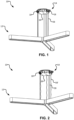
- FIGS 1 and 2 show a luminaire system 10 according to an embodiment of the invention.
- Luminaire system 10 includes a luminaire 12 suspended by a luminaire mounting and suspension assembly 14.
- Assembly 14 includes a mounting unit 16 and a plurality of suspension units 18.
- Suspension units 18 are evenly arranged about mounting unit 16. In the illustrated embodiments three suspension units 18 are provided. In other embodiments, less or more suspension units 18 may be provided.
- Each suspension unit 18 includes a pair of suspension cables 28.
- suspension cables 28 are equally tensioned and taut whereas in Figure 2 suspension cables 28 are taut while suspension cables 28' are slack. That is, Figure 2 shows system 10 before the suspension cables are automatically balanced by the invention as described herein.
- Suspension unit 18 includes a housing 20 and a yoke 22.
- Housing 20 is coupled to mounting unit 16.
- housing 20 may be pivotally coupled to mounting unit 16 at pivot points 48.
- housing 20 may be fixedly coupled, or integrally formed with, mounting unit 16.
- Housing 20 is pivotally coupled to yoke 22 at pivot point 24, so as to be pivotable about a pivot axis.
- a pair of cables grippers 26 is mounted on yoke 22.
- cable grippers 26 may be integrally formed with yoke 22. Cable grippers 26 are configured, as known in the art, to grippingly engage and disengage a suspension cable extending therethrough to adjust the length of suspension cable 28 for suspending luminaire 12.
- Power wires 46 extend from mounting unit 16 to a respective one of cable grippers 26 and connect to a respective one of suspension cables 28 to deliver power to luminaire 12.
- Cable grippers 26 are positioned on yoke 22 equidistantally on either side of pivot point 24.
- the axes of suspension cables 28 are perpendicular to the axis of pivot point 24. Accordingly, once the lengths of suspension cables 28 are set by cable grippers 26, free rotation of yoke 22 about pivot axis evenly balances tension between the pair of suspension cables 28.
- Housing 20 includes a pair of stops 30. In some embodiments, stops 30 are shoulders of sidewalls 36 of housing 20.
- Yoke 22 includes a yoke plate 32 to which cable grippers 26 are fixed. Cable grippers 26 may be aligned along a plane perpendicular to the axis of pivot point 24.
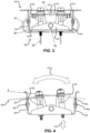
- Yoke plate also has opposing end portions 34. As shown best in Figure 4 , yoke plate 32 spans housing 20 such that an end portion 34 will engage a shoulder 30 at one extreme of range of rotation 50 of yoke 22, and the other end portion 34 will engage the other shoulder 30 at the other extreme of range of rotation 50 of yoke 22.
- Figure 4 shows rotational movement of yoke 22, indicated by arrow 52, and the resulting vertical displacement of cable grippers 26 (and therefore suspension cables 28), indicated by arrow 54. This vertical displacement defines the fine adjustment that evenly balances the tensioning between the pairs of suspension cables 28.
- range of rotation 50 of yoke 22 is limited to no greater than approximately 20 degrees, or approximately 15 degrees, or approximately 10 degrees.
- Yoke plate 32 includes a pair of opposing flanged yoke portions 38 extending perpendicularly from the front and back of yoke plate 32.
- Housing 20 includes a housing plate 40 and a pair of opposing flanged housing portions 42 extending perpendicularly from the front and back of housing plate 40.
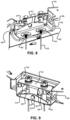
- Pivot point 24 includes a pin 56 rotatably coupling the flanged yoke portions 38 and flanged housing portions 42, as best shown in Figure 9 .
- yoke 22 is positioned on top of housing 20, and the load of luminaire 12 results in compression forces acting on yoke 22 as shown in Figures 5 and 6 .
- the load is uneven (i.e., one cable 28 is taut and the other cable 28' is slack as shown in Figure 2 )
- yoke 22 will pivot until it reaches equilibrium with balanced loads as shown in Figure 6 (i.e., both cables 28 are taut, as shown in Figure 1 ).
- yoke 22 may be positioned below housing 20, and the load of luminaire 12 results in tension forces acting on yoke 22. If the load is uneven, yoke 22 will pivot until it reaches equilibrium as shown in Figure 7 .
- luminaire 12 is restricted from rotating around an axis parallel to the pivot axis. In other words, once equilibrium is achieved in each yoke 22 of assembly 14, luminaire system 10 is stable and not susceptible to oscillation.
- housing 20 may be pivotally coupled to mounting unit 16. In other embodiments, housing 20 may be fixedly coupled, or integrally formed with, mounting unit 16.
- housing plate 40 may include a pair of apertures 44 through which cable grippers 26 and/or suspension cables 28 extend. Apertures 44 are dimensioned to accommodate lateral movement of cable grippers 26 and/or suspension cables 28 as yoke 22 rotates to achieve equilibrium.
- a luminaire system 10 is provided and suspended.
- the limitation of range of motion 50 of yokes 22 allows one of each of the pairs of the suspension cables 28 of each of the suspension units 18 to stably support luminaire 12.
- the length of suspension cables 28 is adjusted using the mechanism of cable grippers 26 until any remaining length discrepancy between each pair of suspension cables 28 can be overcome with the range of motion of yoke 22 of each suspension unit 18 (i.e., vertical displacement 54 shown in Figure 4 ). Then, free rotation of yoke 22 of each suspension unit 18 about its pivot axis will evenly balance tension between the pairs of suspension cables 28 in each of yokes 22 to remove any slack and provide tautness for each suspension cable 28 of luminaire system 10.
- a component e.g. cable wire, projection, etc.
- reference to that component should be interpreted as including as equivalents of that component any component which performs the function of the described component (i.e. that is functionally equivalent), including components which are not structurally equivalent to the disclosed structure which performs the function in the illustrated exemplary embodiments of the invention.
Landscapes
- Engineering & Computer Science (AREA)
- General Engineering & Computer Science (AREA)
- Mechanical Engineering (AREA)
- Arrangement Of Elements, Cooling, Sealing, Or The Like Of Lighting Devices (AREA)
- Non-Portable Lighting Devices Or Systems Thereof (AREA)
Description
- This invention relates to assemblies, systems and methods for balanced suspension of luminaires.
- When suspending luminaires, it is sometimes necessary to have suspension cables arranged in adjacent pairs. This may be for aesthetic reasons, or may be due to the necessity to achieve a certain number of conductors with powered suspension cables.
- Ideally, tension in all of the suspension cables should be even. However, because of granularity in the cable length adjustment mechanisms typically used in suspended luminaires, it is nearly impossible to achieve balanced cable tension in adjacent pairs using these mechanisms alone.
- As suspension cable diameter increases, the increment of length adjustment will also typically increase. For powered suspension cable applications, relatively thick cables are required to reduce electrical resistance. These thick cables lead to coarser increments of length adjustment.
- The result of the inability to make fine adjustments to cable length is that only one cable of the pair will carry the load, while the other is inevitably slack. Slack cables are detrimental to the aesthetics of the luminaire. With coarser cable length adjustment increments, the degree of slackness can quickly become unacceptable.
- Evenly balancing tension between luminaire suspension cables to remove slack is desirable.
-
US 2017/198872 describes a luminaire mounting and suspension assembly comprising a mounting unit and a plurality of suspension units.DE 10 2014 101 729 A1 discloses a device for raising and lowering of a lighting fixture relative to a support attached to a ceiling, the device has a holding element vertically pivotable between edges, which is supported at a middle coupling point of a balance beam. - In one aspect of the invention a luminaire mounting and suspension assembly in accordance with claim 1 is provided. The assembly comprises a mounting unit and a plurality of suspension units. Each suspension unit comprises a housing coupled to the mounting unit and a yoke pivotally coupled to the housing at a pivot point, so as to be pivotable about a pivot axis. The yoke comprises a pair of cable grippers, each cable gripper positioned on opposing sides of each pivot point and configured to grip a suspension cable for suspending a luminaire, wherein the pivot axis is perpendicular to axes of the suspension cables and whereby free rotation of the yoke about the pivot axis evenly balances tension between the suspension cables.
- In some embodiments the housing comprises a pair of stops for limiting the range of rotation of the yoke about the pivot axis. In some embodiments the yoke comprises a yoke plate with opposing end portions, and each sidewall of the housing comprises a shoulder defining the stop, whereby engagement of one of the end portions with a corresponding one of the stops defines a limit of the range of rotation of the yoke. In some embodiments the range of rotation of the yoke is limited to no greater than approximately 20 degrees, or approximately 15 degrees, or approximately 10 degrees.
- In some embodiments the cable grippers are fixedly coupled to the yoke plate. The cable grippers may be aligned along a plane perpendicular to the axis of the pivot axis. In some embodiments the yoke plate comprises a pair of opposing flanged yoke portions extending perpendicularly from the yoke plate, wherein the housing comprises a housing plate and a pair of opposing flanged housing portions extending perpendicularly from the housing plate, and wherein the pivot point includes pivot pin rotatably coupling the flanged yoke portions and flanged housing portions. In some embodiments the yoke is positioned on top of the housing, whereby the yoke is acted on by compression forces due to the load of the luminaire. In other embodiments the yoke is positioned below the housing, whereby the yoke is acted on by tension forces due to the load of the luminaire. The housing plate may comprise a pair of apertures through which the cable grippers and/or suspension cables extend, the apertures dimensioned to accommodate lateral movement of the cable grippers and/or suspension cables due to the free rotation of the yoke.
- In some embodiments the housing is pivotally coupled to the mounting unit. In other embodiments, the housing is fixedly coupled to the mounting unit. In some embodiments the suspension units are evenly arranged about the mounting unit. In some embodiments the assembly comprises a pair of power wires, each power wire extending from the mounting unit to a respective one of the cable grippers and connecting to a respective one of the suspension cables.
- In one aspect of the invention a luminaire system in accordance with
claim 14 is provided. The system comprises a mounting and suspension assembly as described herein and a luminaire suspended by the assembly. - In one aspect of the invention a method of suspending a luminaire in accordance with claim 15 is provided. The method comprises providing and suspending a luminaire system as described herein; allowing the limitation of the range of motion of the yoke of each of the suspension units to support the luminaire by one of the suspension cables of each of the suspension units; adjusting length of the suspension cables with the cable grippers until any remaining length discrepancy between each pair of the suspension cables can be overcome with the range of motion of the yoke of each suspension unit; and allowing free rotation of the yoke of each suspension unit about the pivot axis to evenly balance tension between the pairs of suspension cables in each of the yokes.
- Further aspects and example embodiments are illustrated in the accompanying drawings and/or described in the following description.
- The accompanying drawings illustrate non-limiting example embodiments of the invention.
-
Figure 1 is an isometric view of a luminaire system according to an embodiment of the invention showing the suspension cables in balanced tension. -
Figure 2 is an isometric view of a luminaire system according to the embodiment shown inFigure 1 showing the suspension cables in unbalanced tension. -
Figure 3 is a partial side view of a luminaire mounting and suspension assembly according to an embodiment of the invention. -
Figures 4 is a side view of a suspension unit of the luminaire mounting and suspension assembly according to the embodiment shown inFigure 3 , shown the range of motion of the yoke. -
Figure 5 is a diagram depicting unbalanced forces on the yoke of a suspension unit of the luminaire mounting and suspension assembly according to the embodiment shown inFigure 3 . -
Figure 6 is a diagram depicting balanced forces on the yoke of a suspension unit of the luminaire mounting and suspension assembly according to the embodiment shown inFigure 3 . -
Figure 7 is a diagram depicting balanced forces on the yoke of a suspension unit of a luminaire mounting and suspension assembly according to an embodiment of the invention. -
Figure 8 is a partial bottom isometric view of the luminaire mounting and suspension assembly according to the embodiment shown inFigure 3 . -
Figure 9 is a partial top isometric view of the luminaire mounting and suspension assembly according to the embodiment shown inFigure 3 . - Throughout the following description, specific details are set forth in order to provide a more thorough understanding of the invention. However, the invention may be practiced without these particulars. In other instances, well known elements have not been shown or described in detail to avoid unnecessarily obscuring the invention. Accordingly, the specification and drawings are to be regarded in an illustrative, rather than a restrictive, sense.
- This invention relates to luminaires, and in particular to assemblies, systems and methods for balanced suspension of luminaires where suspension cables are arranged in pairs. Aspects of the invention relate to providing a plurality of suspension units evenly arranged about a mounting unit. Each suspension unit includes a pair of suspension cables from which a luminaire is suspended. Tensioning between each pair of suspension cables is balanced by a yoke mechanism to remove any slack in the suspension cables.
-
Figures 1 and 2 show aluminaire system 10 according to an embodiment of the invention.Luminaire system 10 includes aluminaire 12 suspended by a luminaire mounting andsuspension assembly 14.Assembly 14 includes amounting unit 16 and a plurality ofsuspension units 18.Suspension units 18 are evenly arranged about mountingunit 16. In the illustrated embodiments threesuspension units 18 are provided. In other embodiments, less ormore suspension units 18 may be provided. Eachsuspension unit 18 includes a pair ofsuspension cables 28. - In
Figure 1 suspension cables 28 are equally tensioned and taut whereas inFigure 2 suspension cables 28 are taut while suspension cables 28' are slack. That is,Figure 2 showssystem 10 before the suspension cables are automatically balanced by the invention as described herein. -
Figures 2 ,3 ,5, 6 ,8 and 9 show assembly 14, and inparticular suspension unit 18, in greater detail.Suspension unit 18 includes ahousing 20 and ayoke 22.Housing 20 is coupled to mountingunit 16. In some embodiments,housing 20 may be pivotally coupled to mountingunit 16 at pivot points 48. In other embodiments,housing 20 may be fixedly coupled, or integrally formed with, mountingunit 16. -
Housing 20 is pivotally coupled toyoke 22 atpivot point 24, so as to be pivotable about a pivot axis. In some embodiments, a pair of cables grippers 26 is mounted onyoke 22. In other embodiments,cable grippers 26 may be integrally formed withyoke 22.Cable grippers 26 are configured, as known in the art, to grippingly engage and disengage a suspension cable extending therethrough to adjust the length ofsuspension cable 28 for suspendingluminaire 12.Power wires 46 extend from mountingunit 16 to a respective one ofcable grippers 26 and connect to a respective one ofsuspension cables 28 to deliver power toluminaire 12. -
Cable grippers 26 are positioned onyoke 22 equidistantally on either side ofpivot point 24. The axes ofsuspension cables 28 are perpendicular to the axis ofpivot point 24. Accordingly, once the lengths ofsuspension cables 28 are set bycable grippers 26, free rotation ofyoke 22 about pivot axis evenly balances tension between the pair ofsuspension cables 28. - Rotation of
yoke 22 is limited to a range ofrotation 50 as described herein.Housing 20 includes a pair of stops 30. In some embodiments, stops 30 are shoulders ofsidewalls 36 ofhousing 20.Yoke 22 includes ayoke plate 32 to whichcable grippers 26 are fixed.Cable grippers 26 may be aligned along a plane perpendicular to the axis ofpivot point 24. - Yoke plate also has opposing
end portions 34. As shown best inFigure 4 ,yoke plate 32 spanshousing 20 such that anend portion 34 will engage ashoulder 30 at one extreme of range ofrotation 50 ofyoke 22, and theother end portion 34 will engage theother shoulder 30 at the other extreme of range ofrotation 50 ofyoke 22.Figure 4 shows rotational movement ofyoke 22, indicated byarrow 52, and the resulting vertical displacement of cable grippers 26 (and therefore suspension cables 28), indicated byarrow 54. This vertical displacement defines the fine adjustment that evenly balances the tensioning between the pairs ofsuspension cables 28. - In some embodiments, range of
rotation 50 ofyoke 22 is limited to no greater than approximately 20 degrees, or approximately 15 degrees, or approximately 10 degrees. -
Yoke plate 32 includes a pair of opposingflanged yoke portions 38 extending perpendicularly from the front and back ofyoke plate 32.Housing 20 includes ahousing plate 40 and a pair of opposingflanged housing portions 42 extending perpendicularly from the front and back ofhousing plate 40.Pivot point 24 includes apin 56 rotatably coupling theflanged yoke portions 38 andflanged housing portions 42, as best shown inFigure 9 . - In the illustrated embodiment,
yoke 22 is positioned on top ofhousing 20, and the load ofluminaire 12 results in compression forces acting onyoke 22 as shown inFigures 5 and 6 . As shown inFigure 5 , if the load is uneven (i.e., onecable 28 is taut and the other cable 28' is slack as shown inFigure 2 ), thenyoke 22 will pivot until it reaches equilibrium with balanced loads as shown inFigure 6 (i.e., bothcables 28 are taut, as shown inFigure 1 ). - In other embodiments,
yoke 22 may be positioned belowhousing 20, and the load ofluminaire 12 results in tension forces acting onyoke 22. If the load is uneven,yoke 22 will pivot until it reaches equilibrium as shown inFigure 7 . - Regardless of whether
yoke 22 is positioned above or belowhousing 20, the geometry ofluminaire 12 and the additional suspension units 18 (and their respective suspension cables 28) ensureluminaire 12 is restricted from rotating around an axis parallel to the pivot axis. In other words, once equilibrium is achieved in eachyoke 22 ofassembly 14,luminaire system 10 is stable and not susceptible to oscillation. - As shown best in
Figures 8 and 9 ,housing 20 may be pivotally coupled to mountingunit 16. In other embodiments,housing 20 may be fixedly coupled, or integrally formed with, mountingunit 16. - As shown best in
Figure 8 ,housing plate 40 may include a pair ofapertures 44 through whichcable grippers 26 and/orsuspension cables 28 extend.Apertures 44 are dimensioned to accommodate lateral movement ofcable grippers 26 and/orsuspension cables 28 asyoke 22 rotates to achieve equilibrium. - In operation, a
luminaire system 10 is provided and suspended. The limitation of range ofmotion 50 ofyokes 22 allows one of each of the pairs of thesuspension cables 28 of each of thesuspension units 18 to stably supportluminaire 12. The length ofsuspension cables 28 is adjusted using the mechanism ofcable grippers 26 until any remaining length discrepancy between each pair ofsuspension cables 28 can be overcome with the range of motion ofyoke 22 of each suspension unit 18 (i.e.,vertical displacement 54 shown inFigure 4 ). Then, free rotation ofyoke 22 of eachsuspension unit 18 about its pivot axis will evenly balance tension between the pairs ofsuspension cables 28 in each ofyokes 22 to remove any slack and provide tautness for eachsuspension cable 28 ofluminaire system 10. - Where a component (e.g. cable wire, projection, etc.) is referred to above, unless otherwise indicated, reference to that component (including a reference to a "means") should be interpreted as including as equivalents of that component any component which performs the function of the described component (i.e. that is functionally equivalent), including components which are not structurally equivalent to the disclosed structure which performs the function in the illustrated exemplary embodiments of the invention.
Claims (15)
- A luminaire mounting and suspension assembly (14) comprising:a mounting unit (16);a plurality of suspension units (18),characterized in thateach suspension unit (18) comprises:a housing (20) coupled to the mounting unit (16); anda yoke (22) pivotally coupled to the housing (20) at a pivot point (24) so as to be pivotal about a pivot axis, the yoke (22) comprising a pair of cable grippers (26), each cable gripper (26) positioned on opposing sides of each pivot point (24) and configured to grip a suspension cable (28) for suspending a luminaire (12);wherein the pivot axis is perpendicular to axes of the suspension cables (28); andwhereby free rotation of the yoke (22) about the pivot axis evenly balances tension between the suspension cables (28).
- An assembly (14) according to claim 1 wherein the housing (20) comprises a pair of stops (30) for limiting the range of rotation of the yoke (22) about the pivot axis.
- An assembly (14) according to claim 2 wherein the yoke (22) comprises a yoke plate (32) with opposing end portions (34), and each sidewall (36) of the housing (20) comprises a shoulder defining the stop (30), whereby engagement of one of the end portions (34) with a corresponding one of the stops (30) defines a limit of the range of rotation of the yoke (22).
- An assembly (14) according to claim 3 wherein the range of rotation of the yoke (22) is limited to no greater than approximately 20 degrees, or approximately 15 degrees, or approximately 10 degrees.
- An assembly (14) according to claim 4 wherein the cable grippers (26) are fixedly coupled to the yoke plate (32).
- An assembly (14) according to claim 5 wherein the cable grippers (26) are aligned along a plane perpendicular to the pivot axis.
- An assembly (14) according to claim 6 wherein the yoke plate (32) comprises a pair of opposing flanged yoke portions (38) extending perpendicularly from the yoke plate (32), wherein the housing (20) comprises a housing plate (40) and a pair of opposing flanged housing portions (42) extending perpendicularly from the housing plate (40), and wherein the pivot point includes a pivot pin (56) rotatably coupling the flanged yoke portions (38) and flanged housing portions (42).
- An assembly (14) according to claim 7 wherein the yoke (22) is positioned on top of the housing (20), whereby the yoke (22) is acted on by compression forces due to the load of the luminaire (12).
- An assembly (14) according to claim 8 wherein the housing plate (40) comprises a pair of apertures (44) through which the cable grippers (26) and/or suspension cables (28) extend, the apertures (44) dimensioned to accommodate lateral movement of the cable grippers (26) and/or suspension cables (28) due to the free rotation of the yoke (22).
- An assembly (14) according to claim 7 wherein the yoke (22) is positioned below the housing (20), whereby the yoke (22) is acted on by tension forces due to the load of the luminaire (12).
- An assembly (14) according to claim 1 wherein housing (20) is pivotally or fixedly coupled to the mounting unit (16).
- An assembly (14) according to claim 1 wherein the suspension units (18) are evenly arranged about the mounting unit (16).
- An assembly (14) according to claim 1 further comprising a pair of power wires (46), each power wire (46) extending from the mounting unit (16) to a respective one of the cable grippers (26) and connecting to a respective one of the suspension cables (28).
- A luminaire system (10) comprising:a mounting and suspension assembly (14) according to any one of claims 1 to 13; anda luminaire (12) suspended by the assembly (14).
- A method of suspending a luminaire (12) comprising:(a) providing and suspending a luminaire system (10) according to claim 14;(b) allowing the limitation of the range of motion of the yoke (22) of each of the suspension units (18) to support the luminaire (12) by one of the suspension cables (28) of each of the suspension units (18);(c) adjusting length of the suspension cables (28) with the cable grippers (26) until any remaining length discrepancy between each pair of the suspension cables (28) can be overcome with the range of motion of the yoke (22) of each suspension unit (18); and(d) allowing free rotation of the yoke (22) of each suspension unit (18) about the pivot axis to evenly balance tension between the pairs of suspension cables (28) in each of the yokes (22).
Applications Claiming Priority (2)
| Application Number | Priority Date | Filing Date | Title |
|---|---|---|---|
| US201862663588P | 2018-04-27 | 2018-04-27 | |
| PCT/CA2019/050546 WO2019204944A1 (en) | 2018-04-27 | 2019-04-26 | Assemblies, systems and methods for balanced suspension of luminaires |
Publications (4)
| Publication Number | Publication Date |
|---|---|
| EP3784955A1 EP3784955A1 (en) | 2021-03-03 |
| EP3784955A4 EP3784955A4 (en) | 2022-01-12 |
| EP3784955B1 true EP3784955B1 (en) | 2024-09-25 |
| EP3784955C0 EP3784955C0 (en) | 2024-09-25 |
Family
ID=68293445
Family Applications (1)
| Application Number | Title | Priority Date | Filing Date |
|---|---|---|---|
| EP19791817.0A Active EP3784955B1 (en) | 2018-04-27 | 2019-04-26 | Assemblies, systems and methods for balanced suspension of luminaires |
Country Status (4)
| Country | Link |
|---|---|
| US (1) | US11512842B2 (en) |
| EP (1) | EP3784955B1 (en) |
| ES (1) | ES2994666T3 (en) |
| WO (1) | WO2019204944A1 (en) |
Families Citing this family (10)
| Publication number | Priority date | Publication date | Assignee | Title |
|---|---|---|---|---|
| US11718986B2 (en) | 2018-03-01 | 2023-08-08 | Molo Design, Ltd. | Hanging wall systems with diffuse lighting |
| USD933860S1 (en) * | 2018-06-08 | 2021-10-19 | Luceplan S.R.L. | Lighting fixture |
| USD922656S1 (en) * | 2019-02-15 | 2021-06-15 | Molo Design, Ltd. | Light fixture |
| WO2023131473A1 (en) * | 2022-01-04 | 2023-07-13 | Signify Holding B.V. | An adjustable suspensible device |
| USD1062003S1 (en) | 2022-08-22 | 2025-02-11 | 3Form, Llc | Hexagonal-shaped light fixture |
| USD1062002S1 (en) * | 2022-08-22 | 2025-02-11 | 3Form, Llc | X-shaped light fixture |
| USD1054617S1 (en) | 2022-08-22 | 2024-12-17 | 3Form, Llc | T-shaped light fixture |
| USD1062004S1 (en) * | 2022-08-22 | 2025-02-11 | 3Form, Llc | Y-shaped light fixture |
| CA237293S (en) | 2022-10-19 | 2025-04-16 | Molo Design Ltd | Hanging partition |
| USD1110573S1 (en) | 2023-04-19 | 2026-01-27 | Molo Design, Ltd. | Ceiling lamp |
Family Cites Families (15)
| Publication number | Priority date | Publication date | Assignee | Title |
|---|---|---|---|---|
| DE3727301A1 (en) | 1987-08-17 | 1989-03-02 | Christoph Schuster | ADJUSTABLE LAMP |
| DE19845752A1 (en) * | 1998-10-05 | 2000-04-13 | Falcon Design & Technik Gmbh | Adjustable device for holding lamps includes a suspension device for fastening up lamps with one or more adjustable support cables for supplying power. |
| US6471374B1 (en) | 2000-06-30 | 2002-10-29 | Genlyte Thomas Group Llc | Accent light adjustable assembly |
| US6517222B1 (en) * | 2001-08-01 | 2003-02-11 | Linear Lighting Corp. | System and method for leveling suspended lighting fixtures and a longitudunal axis |
| DE202005014393U1 (en) | 2005-09-08 | 2005-11-17 | Arnold & Richter Cine Technik Gmbh & Co. Betriebs Kg | Mounting bracket for e.g. studio headlight, has clamp supports arranged at its end sections for admission of headlight housing, where distance between supports is adjustable by using spindle drive that is provided with safety clutch |
| US8057077B2 (en) * | 2005-12-23 | 2011-11-15 | Canlyte Inc. | Support device |
| DE202007017625U1 (en) * | 2007-12-14 | 2009-04-23 | Aloys Fischer Gmbh | Height adjustable pendant light |
| CH699116A1 (en) | 2008-07-14 | 2010-01-15 | Regent Beleuchtungskoerper Ag | Lamp. |
| GB0904522D0 (en) * | 2009-03-17 | 2009-04-29 | Bond Peter M Lord | Bonds hoisting system |
| DE202011004963U1 (en) * | 2011-04-07 | 2011-08-10 | Michael An Haack | Electric shuttle light |
| US9890937B2 (en) | 2011-10-16 | 2018-02-13 | Robert E. Townsend, Jr. | Devices and systems for improved traffic control signal assembly |
| DE102014101729B4 (en) * | 2014-01-22 | 2016-06-16 | Alfred Korsch | Device for raising and lowering a lighting fixture od. Like. Relative to a stationary to be attached, downwardly open holder |
| US9879845B2 (en) * | 2016-01-07 | 2018-01-30 | Robert A. Sonneman | Modular lighting system using hangers and power bars |
| US10704775B2 (en) * | 2017-03-24 | 2020-07-07 | Swarovski Lighting, Ltd. | Adjustably configurable suspended fixtures, lighting fixtures, and method for suspending fixtures and lighting fixtures |
| WO2019108652A1 (en) * | 2017-11-28 | 2019-06-06 | Contemporary Visions, LLC | Lighting system |
-
2019
- 2019-04-26 EP EP19791817.0A patent/EP3784955B1/en active Active
- 2019-04-26 US US17/046,280 patent/US11512842B2/en active Active
- 2019-04-26 WO PCT/CA2019/050546 patent/WO2019204944A1/en not_active Ceased
- 2019-04-26 ES ES19791817T patent/ES2994666T3/en active Active
Also Published As
| Publication number | Publication date |
|---|---|
| ES2994666T3 (en) | 2025-01-29 |
| US11512842B2 (en) | 2022-11-29 |
| EP3784955A1 (en) | 2021-03-03 |
| US20210071853A1 (en) | 2021-03-11 |
| WO2019204944A1 (en) | 2019-10-31 |
| EP3784955C0 (en) | 2024-09-25 |
| EP3784955A4 (en) | 2022-01-12 |
Similar Documents
| Publication | Publication Date | Title |
|---|---|---|
| US11512842B2 (en) | Assemblies, systems and methods for balanced suspension of luminaires | |
| US11557824B2 (en) | Antenna mounting device and base station antenna system | |
| EP3150541A1 (en) | Hook block and rope hoist | |
| KR101024895B1 (en) | Arcing Horn Device for Jumper Support of Transmission Line | |
| CN109546287B (en) | 5G single-pivot antenna support | |
| CN101694792A (en) | Duplex-joint V-shaped suspended insulator chain for ultrahigh voltage transmission line | |
| US20160102891A1 (en) | Device for Supporting a Length of a Control Bar of a Solar Tracking System | |
| JP2012060824A (en) | Jumper cable reinforcing device | |
| CN104787688B (en) | A kind of oblique attachment device | |
| US4039141A (en) | Grounding accessory for a bundle conductor stringing block | |
| CZ2003560A3 (en) | Pole top support for aerial electric power lines | |
| EP4222385B1 (en) | Suspension assembly | |
| JP3227044U (en) | Stabilizer | |
| US9573790B2 (en) | Suspension device and suspension arrangement | |
| CN114506495A (en) | Double-wire-drawing device for cigarette packet | |
| CN208479023U (en) | A portable insulated operating platform | |
| KR20210061807A (en) | Suspension clamp | |
| JPH10505569A (en) | Elevator car mounting, balancing device and methods thereof | |
| JP2004035171A (en) | Trolley crane and its operation method | |
| US4093183A (en) | Unitary grounding assembly for bundle conductor stringing blocks | |
| KR101106897B1 (en) | Fixture of vehicle payload | |
| RU219443U1 (en) | Device for compensating the tension of the wires of the contact network | |
| CN214227776U (en) | An adjustable insulator jumper structure | |
| CN120896065A (en) | An adjustable anti-torsion tension connecting plate | |
| CN211455933U (en) | Antenna mounting device and base station antenna system |
Legal Events
| Date | Code | Title | Description |
|---|---|---|---|
| STAA | Information on the status of an ep patent application or granted ep patent |
Free format text: STATUS: THE INTERNATIONAL PUBLICATION HAS BEEN MADE |
|
| PUAI | Public reference made under article 153(3) epc to a published international application that has entered the european phase |
Free format text: ORIGINAL CODE: 0009012 |
|
| STAA | Information on the status of an ep patent application or granted ep patent |
Free format text: STATUS: REQUEST FOR EXAMINATION WAS MADE |
|
| 17P | Request for examination filed |
Effective date: 20201126 |
|
| AK | Designated contracting states |
Kind code of ref document: A1 Designated state(s): AL AT BE BG CH CY CZ DE DK EE ES FI FR GB GR HR HU IE IS IT LI LT LU LV MC MK MT NL NO PL PT RO RS SE SI SK SM TR |
|
| AX | Request for extension of the european patent |
Extension state: BA ME |
|
| DAV | Request for validation of the european patent (deleted) | ||
| DAX | Request for extension of the european patent (deleted) | ||
| RAP1 | Party data changed (applicant data changed or rights of an application transferred) |
Owner name: LMPG INC. DBA FLUXWERX ILLUMINATION |
|
| A4 | Supplementary search report drawn up and despatched |
Effective date: 20211214 |
|
| RIC1 | Information provided on ipc code assigned before grant |
Ipc: F16M 13/02 20060101ALN20211208BHEP Ipc: F16G 11/12 20060101ALN20211208BHEP Ipc: F21V 21/30 20060101ALI20211208BHEP Ipc: F21V 21/02 20060101ALI20211208BHEP Ipc: F21S 8/06 20060101ALI20211208BHEP Ipc: F21V 21/104 20060101AFI20211208BHEP |
|
| RAP3 | Party data changed (applicant data changed or rights of an application transferred) |
Owner name: LMPG INC. |
|
| REG | Reference to a national code |
Ref country code: DE Free format text: PREVIOUS MAIN CLASS: F21V0021008000 Ref country code: DE Ref legal event code: R079 Ref document number: 602019059483 Country of ref document: DE Free format text: PREVIOUS MAIN CLASS: F21V0021008000 Ipc: F21V0021104000 |
|
| GRAP | Despatch of communication of intention to grant a patent |
Free format text: ORIGINAL CODE: EPIDOSNIGR1 |
|
| STAA | Information on the status of an ep patent application or granted ep patent |
Free format text: STATUS: GRANT OF PATENT IS INTENDED |
|
| RIC1 | Information provided on ipc code assigned before grant |
Ipc: F16M 13/02 20060101ALN20240325BHEP Ipc: F16G 11/12 20060101ALN20240325BHEP Ipc: F21V 21/30 20060101ALI20240325BHEP Ipc: F21V 21/02 20060101ALI20240325BHEP Ipc: F21S 8/06 20060101ALI20240325BHEP Ipc: F21V 21/104 20060101AFI20240325BHEP |
|
| RIC1 | Information provided on ipc code assigned before grant |
Ipc: F16M 13/02 20060101ALN20240410BHEP Ipc: F16G 11/12 20060101ALN20240410BHEP Ipc: F21V 21/30 20060101ALI20240410BHEP Ipc: F21V 21/02 20060101ALI20240410BHEP Ipc: F21S 8/06 20060101ALI20240410BHEP Ipc: F21V 21/104 20060101AFI20240410BHEP |
|
| INTG | Intention to grant announced |
Effective date: 20240426 |
|
| GRAS | Grant fee paid |
Free format text: ORIGINAL CODE: EPIDOSNIGR3 |
|
| GRAA | (expected) grant |
Free format text: ORIGINAL CODE: 0009210 |
|
| STAA | Information on the status of an ep patent application or granted ep patent |
Free format text: STATUS: THE PATENT HAS BEEN GRANTED |
|
| AK | Designated contracting states |
Kind code of ref document: B1 Designated state(s): AL AT BE BG CH CY CZ DE DK EE ES FI FR GB GR HR HU IE IS IT LI LT LU LV MC MK MT NL NO PL PT RO RS SE SI SK SM TR |
|
| REG | Reference to a national code |
Ref country code: GB Ref legal event code: FG4D |
|
| REG | Reference to a national code |
Ref country code: CH Ref legal event code: EP |
|
| REG | Reference to a national code |
Ref country code: DE Ref legal event code: R096 Ref document number: 602019059483 Country of ref document: DE |
|
| REG | Reference to a national code |
Ref country code: IE Ref legal event code: FG4D |
|
| U01 | Request for unitary effect filed |
Effective date: 20241024 |
|
| U07 | Unitary effect registered |
Designated state(s): AT BE BG DE DK EE FI FR IT LT LU LV MT NL PT RO SE SI Effective date: 20241105 |
|
| PG25 | Lapsed in a contracting state [announced via postgrant information from national office to epo] |
Ref country code: NO Free format text: LAPSE BECAUSE OF FAILURE TO SUBMIT A TRANSLATION OF THE DESCRIPTION OR TO PAY THE FEE WITHIN THE PRESCRIBED TIME-LIMIT Effective date: 20241225 |
|
| PG25 | Lapsed in a contracting state [announced via postgrant information from national office to epo] |
Ref country code: GR Free format text: LAPSE BECAUSE OF FAILURE TO SUBMIT A TRANSLATION OF THE DESCRIPTION OR TO PAY THE FEE WITHIN THE PRESCRIBED TIME-LIMIT Effective date: 20241226 |
|
| PG25 | Lapsed in a contracting state [announced via postgrant information from national office to epo] |
Ref country code: RS Free format text: LAPSE BECAUSE OF FAILURE TO SUBMIT A TRANSLATION OF THE DESCRIPTION OR TO PAY THE FEE WITHIN THE PRESCRIBED TIME-LIMIT Effective date: 20241225 |
|
| REG | Reference to a national code |
Ref country code: ES Ref legal event code: FG2A Ref document number: 2994666 Country of ref document: ES Kind code of ref document: T3 Effective date: 20250129 |
|
| PG25 | Lapsed in a contracting state [announced via postgrant information from national office to epo] |
Ref country code: RS Free format text: LAPSE BECAUSE OF FAILURE TO SUBMIT A TRANSLATION OF THE DESCRIPTION OR TO PAY THE FEE WITHIN THE PRESCRIBED TIME-LIMIT Effective date: 20241225 Ref country code: NO Free format text: LAPSE BECAUSE OF FAILURE TO SUBMIT A TRANSLATION OF THE DESCRIPTION OR TO PAY THE FEE WITHIN THE PRESCRIBED TIME-LIMIT Effective date: 20241225 Ref country code: GR Free format text: LAPSE BECAUSE OF FAILURE TO SUBMIT A TRANSLATION OF THE DESCRIPTION OR TO PAY THE FEE WITHIN THE PRESCRIBED TIME-LIMIT Effective date: 20241226 |
|
| PG25 | Lapsed in a contracting state [announced via postgrant information from national office to epo] |
Ref country code: IS Free format text: LAPSE BECAUSE OF FAILURE TO SUBMIT A TRANSLATION OF THE DESCRIPTION OR TO PAY THE FEE WITHIN THE PRESCRIBED TIME-LIMIT Effective date: 20250125 |
|
| PG25 | Lapsed in a contracting state [announced via postgrant information from national office to epo] |
Ref country code: SM Free format text: LAPSE BECAUSE OF FAILURE TO SUBMIT A TRANSLATION OF THE DESCRIPTION OR TO PAY THE FEE WITHIN THE PRESCRIBED TIME-LIMIT Effective date: 20240925 |
|
| PG25 | Lapsed in a contracting state [announced via postgrant information from national office to epo] |
Ref country code: PL Free format text: LAPSE BECAUSE OF FAILURE TO SUBMIT A TRANSLATION OF THE DESCRIPTION OR TO PAY THE FEE WITHIN THE PRESCRIBED TIME-LIMIT Effective date: 20240925 Ref country code: CZ Free format text: LAPSE BECAUSE OF FAILURE TO SUBMIT A TRANSLATION OF THE DESCRIPTION OR TO PAY THE FEE WITHIN THE PRESCRIBED TIME-LIMIT Effective date: 20240925 |
|
| PG25 | Lapsed in a contracting state [announced via postgrant information from national office to epo] |
Ref country code: SK Free format text: LAPSE BECAUSE OF FAILURE TO SUBMIT A TRANSLATION OF THE DESCRIPTION OR TO PAY THE FEE WITHIN THE PRESCRIBED TIME-LIMIT Effective date: 20240925 |
|
| U20 | Renewal fee for the european patent with unitary effect paid |
Year of fee payment: 7 Effective date: 20250428 |
|
| PGFP | Annual fee paid to national office [announced via postgrant information from national office to epo] |
Ref country code: GB Payment date: 20250428 Year of fee payment: 7 |
|
| PLBE | No opposition filed within time limit |
Free format text: ORIGINAL CODE: 0009261 |
|
| STAA | Information on the status of an ep patent application or granted ep patent |
Free format text: STATUS: NO OPPOSITION FILED WITHIN TIME LIMIT |
|
| 26N | No opposition filed |
Effective date: 20250626 |
|
| REG | Reference to a national code |
Ref country code: CH Ref legal event code: H13 Free format text: ST27 STATUS EVENT CODE: U-0-0-H10-H13 (AS PROVIDED BY THE NATIONAL OFFICE) Effective date: 20251125 |
|
| PG25 | Lapsed in a contracting state [announced via postgrant information from national office to epo] |
Ref country code: MC Free format text: LAPSE BECAUSE OF FAILURE TO SUBMIT A TRANSLATION OF THE DESCRIPTION OR TO PAY THE FEE WITHIN THE PRESCRIBED TIME-LIMIT Effective date: 20240925 |
|
| PG25 | Lapsed in a contracting state [announced via postgrant information from national office to epo] |
Ref country code: HR Free format text: LAPSE BECAUSE OF FAILURE TO SUBMIT A TRANSLATION OF THE DESCRIPTION OR TO PAY THE FEE WITHIN THE PRESCRIBED TIME-LIMIT Effective date: 20240925 |
|
| PG25 | Lapsed in a contracting state [announced via postgrant information from national office to epo] |
Ref country code: CH Free format text: LAPSE BECAUSE OF NON-PAYMENT OF DUE FEES Effective date: 20250430 |
|
| PG25 | Lapsed in a contracting state [announced via postgrant information from national office to epo] |
Ref country code: IE Free format text: LAPSE BECAUSE OF NON-PAYMENT OF DUE FEES Effective date: 20250426 |