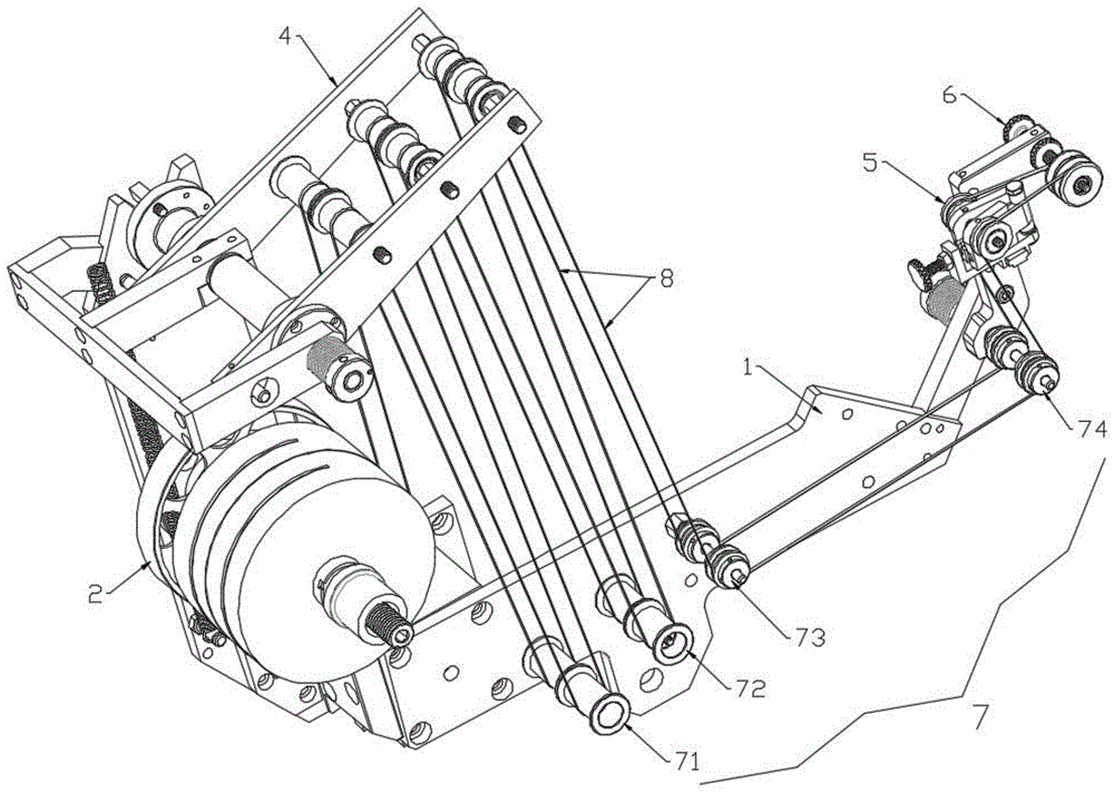
Double-wire-drawing device for cigarette packet
Technical Field
The invention relates to the technical field of cigarette packaging equipment, in particular to a double cigarette packet pull line device.
Background
With the improvement of market demand and the development of various novel cigarette packet packages, the cigarette industry provides a double-wire drawing process of the cigarette packet on a product structure. For example, CN209634885U provides a cigarette case with a dual-string structure, in which two strings are respectively located at the upper and lower ends of the cigarette case, but the two strings are far apart from each other, so that consumers need to tear down the strings from different positions. The production of the cigarette packet needs a special cigarette packet double-stay wire laminating device.
Patent ZL200820074596.X increases a set of laminating device on the basis of current single laminating mechanism of acting as go-between, has proposed the two laminating devices that act as go-between of a tobacco bale. However, because two sets of bonding devices are used, the structure is complex and the debugging is troublesome, so that it is particularly necessary to develop a dual-pulling-wire device with a simpler structure.
Disclosure of Invention
The invention provides a double-stay-wire device for cigarette packets, which aims to solve the problems of complex structure and troublesome debugging of a double-stay-wire laminating device in the prior art.
The technical scheme adopted by the invention is as follows: provided is a dual string drawing device for cigarette packets, comprising:
a main frame;
the double-stay-wire paper feeding roller mechanism comprises a transmission shaft arranged on the main frame, a friction wheel arranged on the transmission shaft and two paper feeding rollers;
the damping mechanism is arranged on the main frame, is in contact with the friction wheel and is used for preventing the rebound of the paper feeding roller;
the double-swing-rod guide roller mechanism is arranged on the main frame and comprises two groups of guide roller sets which independently run;
the multi-stage progressive guide roller mechanisms are all arranged on the main frame and extend to the tail end of the main frame;
the guide angle adjusting mechanism is arranged at the tail end of the main frame and used for adjusting the angle of the double pull wires;
and the adjustable final guide roller is arranged at the tail end of the total rack and used for carrying out final distance adjustment on the double pull wires coming out of the guide angle adjusting mechanism.
Further, double pendulum rod deflector roll mechanism includes:
one end of the rotating shaft is fixed on the main frame;
the middle part of the first tensioning swing rod is rotationally connected with the rotating shaft, and a first guide roller set is fixed at one end of the first tensioning swing rod;
one end of the tension spring is fixed on the main frame, and the other end of the tension spring is fixed at the other end of the first tensioning swing rod and used for providing tension for the other end of the first tensioning swing rod;
the middle part of the second tensioning swing rod is rotatably connected with the rotating shaft, a second guide roller set is fixed at one end of the second tensioning swing rod, and the first guide roller set is not connected with the second guide roller set;
a support plate assembly for providing a support force to the rotation shaft; and
the torsion spring is used for providing torsion when the second tensioning swing rod rotates;
during operation, the tension of acting as go-between on first guide roller set and the second guide roller set is adjusted respectively to extension spring and torsional spring, realizes the independent even running of two acting as go-between.
Further, the double-swing-rod guide roller mechanism further comprises:
the first sliding bearing is sleeved on the rotating shaft, and the first tensioning swing rod is fixed on the first sliding bearing; and the number of the first and second groups,
the second tensioning swing rod is fixed on the second sliding bearing;
a first limiting rod is arranged on the first sliding bearing or the first tensioning swing rod, and a notch for limiting the first limiting rod is arranged on the main rack;
and one end of the torsion spring is fixed on the third sliding bearing, and the other end of the torsion spring is fixed on the supporting plate component.
Further, the supporting plate assembly comprises a supporting plate, and a first supporting plate, a second supporting plate and a third supporting plate which are fixed on the supporting plate;
the first supporting plate is fixed on the rack;
the second support plate is fixed on the rotating shaft, or the second support plate is fixed on a shaft sleeve sleeved on the rotating shaft;
one end of the torsion spring is fixed on the third support plate, and the other end of the torsion spring is fixed on the third sliding bearing;
the other end of the second tensioning swing rod is provided with a second limiting rod, and the third support plate is provided with a limiting hole for limiting the second limiting rod.
Further, the first guide roller group and the second guide roller group are respectively provided with three guide rollers, and gaps in the middle of the guide rollers are reduced in sequence.
Further, the multistage progressive guide roller mechanism comprises a third guide roller set, a fourth guide roller set, a fifth guide roller set and a sixth guide roller set; and the third guide roller group, the fourth guide roller group, the fifth guide roller group and the sixth guide roller group respectively comprise a guide roller shaft and two guide rollers which are independently rotated on the guide roller shaft.
Further, the damping mechanism includes:
the support is arranged on the general frame;
one end of the balance shaft is connected to the support;
a self-balancing block mounted on the other end of the balancing shaft;
the spring is sleeved on the balance shaft, is positioned between the support and the self-balancing block and is always in a compressed state;
the guide shaft is connected between the support and the self-balancing block;
the friction layer is arranged on the surface of the self-balancing block and is in contact with the friction wheel;
and the adjusting nut is arranged on the balance shaft and used for adjusting the compression amount of the spring.
Further, the guide angle adjusting mechanism includes:
the first adjusting plate and the second adjusting plate are hinged through the shaft core to form a V-shaped structure;
the first roller and the second roller are respectively arranged on the outer side walls of the first adjusting plate and the second adjusting plate;
the connecting frame is mounted on the main frame, and the adjusting bracket is slidably mounted on the connecting frame; and
the adjusting component is installed with the axle center on adjusting the support, the adjusting component is used for adjusting the opening angle size between first regulating plate and the second regulating plate.
Furthermore, the adjusting assembly comprises a first adjusting bolt, a wedge-shaped adjusting block, a first locking nut, a first T-shaped sliding block, a second T-shaped sliding block and a third T-shaped sliding block; the inner side walls of the first adjusting plate and the second adjusting plate are respectively provided with a first T-shaped chute and a second T-shaped chute which are vertical to the direction of the shaft core; the second T-shaped sliding block and the third T-shaped sliding block are fixedly arranged on two sides of the wedge-shaped adjusting block respectively, and the second T-shaped sliding block and the third T-shaped sliding block slide in the first T-shaped sliding groove and the second T-shaped sliding groove respectively; the first adjusting bolt is in threaded connection with a threaded hole formed in the adjusting bracket, a third T-shaped sliding groove parallel to the direction of the shaft core is formed in the wedge-shaped adjusting block, one end of the first T-shaped sliding block is located in the third T-shaped sliding groove, and the other end of the first T-shaped sliding block is fixedly connected with one end of the first adjusting bolt; the first locking nut is sleeved on the first adjusting bolt.
Further, the adjustable final guide roller comprises:
the second adjusting bolt is arranged at the tail end of the main frame;
the second locking nut is arranged on the second adjusting bolt;
the eighth guide roller group comprises two guide rollers and is arranged on the second adjusting bolt;
and the positioning sleeve is arranged on the second adjusting bolt and is positioned between the two guide rollers of the eighth guide roller set.
The invention has the beneficial effects that:
1) the double-pull-wire device of the cigarette packet is characterized in that independent electric drive and electric control are not needed, the double-swing-rod guide roller mechanism is provided with two mutually independent tensioning swing rods, when double pull wires are installed on the wires, the two pull wires are independently wound with each roller, the installation and the use are convenient, in the conveying and running process, the balance is formed by a damping mechanism on the double pull wire guide roller mechanism, the double pull wire paper feeding roller mechanism is ensured to avoid paper roll rebound while in unpowered free rotation, and meanwhile, the angle and the transverse position on the guide angle adjusting mechanism are adjusted before the double pull wires enter the adjustable ultimate guide roller with the position adjusted according to the technological requirements, so that the double pull wire transmission purpose is achieved.
2) The device simple structure, the integrated level is high, simple to operate, and it is nimble to adjust, the good reliability, reduce cost. By using the technology, the technological requirements of products can be met, and the running efficiency of the original machine of the equipment can be achieved.
Drawings
Fig. 1 is a schematic structural view of a cigarette packet double-pulling-wire device without winding double pulling wires disclosed by the embodiment of the invention.
Fig. 2 is a schematic structural view of a cigarette packet double-pulling-line device wound with double pulling lines, which is disclosed by the embodiment of the invention.
Fig. 3 is a schematic structural diagram of a double-swing-rod guide roller mechanism disclosed in the embodiment of the invention.
Fig. 4 is another schematic structural diagram of the double-swing-rod guide roller mechanism disclosed in the embodiment of the invention.
Fig. 5 is a schematic structural diagram of a damping mechanism and a double-stay-wire paper feeding roller mechanism disclosed by the embodiment of the invention.
Fig. 6 is a schematic structural diagram of a guide angle adjusting mechanism disclosed in the embodiment of the present invention.
Fig. 7 is a front view of a guide angle adjusting mechanism disclosed in an embodiment of the present invention.
Fig. 8 is a left side view of the guide angle adjusting mechanism disclosed in the embodiment of the present invention.
Fig. 9 is a top view of the guide angle adjusting mechanism according to the embodiment of the present invention.
Fig. 10 is a schematic structural view of an adjustable final guide roller according to an embodiment of the present invention.
Reference numerals: 1. a main frame; 11. a notch;
2. a double-stay-wire paper feeding roller mechanism; 21. a paper feed roller; 22. a drive shaft; 23. locking a hand wheel; 24. a friction wheel;
3. a damping mechanism; 31. a support; 32. a balance shaft; 33. a self-balancing mass; 34. a spring; 35. a friction layer; 36. adjusting the nut; 37. a guide shaft; 38. pressing a plate;
4. a double-swing-rod guide roller mechanism; 41. a first tensioning swing rod; 411. a first guide roller set; 412. a first limit rod; 413. a pull rod; 42. a second tensioning swing rod; 421. a second guide roller set; 422. a second limiting rod; 43. a tension spring; 44. a torsion spring; 45. a rotating shaft; 46. a support plate; 461. a first support plate; 462. a second support plate; 463. a third support plate; 4631. a limiting hole; 47. a first sliding bearing; 48. a second sliding bearing; 49. a third sliding bearing;
5. a guide angle adjusting mechanism; 51. a connecting frame; 52. adjusting the bracket; 521. a slider; 53. a first adjusting bolt; 531. a first T-shaped slider; 54. a shaft core; 55. a first roller; 56. a second roller; 57. a first adjusting plate; 571. a first T-shaped chute; 58. a second adjusting plate; 581. a second T-shaped chute; 59. a wedge-shaped adjusting block; 591. a third T-shaped chute; 592. a second T-shaped slider; 510. a first lock nut;
6. adjustable ultimate guide roller; 61. a second adjusting bolt; 62. a second lock nut; 63. an eighth guide roller set; 64. a positioning sleeve;
7. a multi-stage progressive guide roller mechanism; 71. a third guide roller set; 72. a fourth guide roller set; 73. a fifth guide roller set; 74. a sixth guide roller set;
8. double pull wires.
Detailed Description
In order to make the objects, technical solutions and advantages of the present invention more apparent, the present invention will be described in further detail with reference to the accompanying drawings, but embodiments of the present invention are not limited thereto.
Example 1:
referring to fig. 1-2, a dual string stretcher for cigarette packets comprises: a main frame 1; the double-stay-wire paper feeding roller mechanism 2 comprises a transmission shaft 22 arranged on the main frame 1, a friction wheel 24 arranged on the transmission shaft 22 and two paper feeding rollers 21, wherein the two paper feeding rollers 21 are locked by a locking hand wheel 23 arranged on the transmission shaft 22; a damping mechanism 3 mounted on the main frame 1 and contacting the friction wheel 24 for preventing the paper feeding roller 21 from rebounding; the double-swing-rod guide roller mechanism 4 is arranged on the main frame 1 and comprises two groups of guide roller sets which operate independently; the multi-stage progressive guide roller mechanisms 7 are all arranged on the main frame 1 and extend to the tail end of the main frame 1; the guide angle adjusting mechanism 5 is arranged at the tail end of the main frame 1 and used for adjusting the angle of the double pull wires 8; and the adjustable final guide roller 6 is arranged at the tail end of the main frame 1 and used for carrying out final distance adjustment on the double pull wires 8 coming out of the guide angle adjusting mechanism 5.
Referring to fig. 3-4, in this embodiment, the double-swing link guide roller mechanism includes: a rotating shaft 45, one end of which is fixed on the frame; the middle part of the first tensioning swing rod 41 is rotatably connected with the rotating shaft 45, and a first guide roller set 411 is fixed at one end of the first tensioning swing rod 41; the tension spring 43 is used for providing tension to the other end of the first tensioning swing rod 41, specifically, one end of the tension spring 43 is fixed on the main frame 1, and the other end of the tension spring 43 is fixed on the pull rod 413 arranged at the other end of the first tensioning swing rod 41; the middle part of the second tensioning swing rod 42 is rotatably connected with the rotating shaft 45, a second guide roller set 421 is fixed at one end of the second tensioning swing rod 42, and the first guide roller set 411 and the second guide roller set 421 are not connected and operate independently; a support plate assembly for providing a supporting force to the rotation shaft 45; and a torsion spring 44 for providing a torsion force when the second tension lever 42 rotates.
In this embodiment, the first tensioning swing link 41 and the second tensioning swing link 42 are integrated on a rotating shaft 45, and each set of guide rollers can adjust different pulling forces (torsion) through respective spring structures to overcome the external force applied to each pull wire, so that the double pull wires can independently and stably run.
In this embodiment, the first sliding bearing 47 is provided to realize the rotational connection between the first tensioning swing link 41 and the rotating shaft 45, specifically, the first sliding bearing 47 is sleeved on the rotating shaft 45, and the first tensioning swing link 41 is fixed on the first sliding bearing 47.
In this embodiment, in order to ensure that both the double pulling wires can run smoothly, the swing of the first tensioning swing link 41 cannot be too large, so that the gap 11 is designed on the main frame 1, and the first sliding bearing 47 or the first tensioning swing link 41 is provided with the first limiting rod 412, so that the gap 11 becomes the maximum movement margin of the first limiting rod 412, that is, the maximum movement margin of the first tensioning swing link 41.
In this embodiment, the second tensioning swing rod 42 is rotatably connected to the rotating shaft 45 by providing a third sliding bearing 49, specifically, the third sliding bearing 49 is sleeved on the rotating shaft 45, the second tensioning swing rod 42 is fixed to the third sliding bearing 49, in order to ensure that the second tensioning swing rod 42 rotates more stably, a second sliding bearing 48 may be further sleeved on the rotating shaft 45, and the second tensioning swing rod 42 is fixed between the second sliding bearing 48 and the third sliding bearing 49.
It is to be noted that the rotation shaft 45 is fixedly mounted on the overall frame 1, the rotation shaft 45 being non-rotatable with respect to the overall frame 1. The first tensioning swing rod 41 is fixed on a first sliding bearing 47 and can independently rotate around the rotating shaft 45; the second tensioning swing rod 42 is fixed on a second sliding bearing 48 and a third sliding bearing 49 and can also independently rotate around the rotating shaft 45; in addition, there is no connection between the first guide roller group 411 and the second guide roller group 421, so that the first tension lever 41 and the second tension lever 42 rotate on the rotation shaft 45 independently of each other.
In this embodiment, the support plate assembly includes a support plate 46 and a first support plate 461 and a second support plate 462 fixed to the support plate 46, and supports the rotating shaft 45. The first support plate 461 is fixed on the general frame 1; the second support plate 462 is fixed to the rotating shaft 45, and the second support plate 462 may also be fixed to a sleeve (not shown) that is sleeved on the rotating shaft 45. The rotary shaft 45 can be vertically fixed to the overall frame 1 by fixing the first support plate 461 and the second support plate 462.
In this embodiment, the support plate assembly further includes a third support plate 463 fixed to the support plate 46, and the torsion spring 44 has one end (left end in fig. 3) fixed to the third support plate 463 and the other end (right end in fig. 3) fixed to the third sliding bearing 49. Specifically, as shown in fig. 3, a through hole may be provided in the third support plate 463, and the through hole is located in the outer ring of the third sliding bearing 49 and has no connection relation with the third sliding bearing 49.
In this embodiment, the other end of the second tensioning swing link 42 is provided with a second limiting rod 422, and the third support plate 463 is provided with a limiting hole 4631 for limiting the second limiting rod 422. The function of the limiting hole 4631 is the same as that of the notch 11 provided in the switchboard 1, and will not be described again.
The torsion spring 44 is provided to provide a buffer for the rotation of the second tensioning rocker 42, so that in other embodiments, a third support plate may not be provided, the torsion spring 44 being fixed at one end to the third slide bearing 49 and at the other end to the rotary shaft 45.
In this embodiment, the first guide roller set 411 and the second guide roller set 421 respectively have three guide rollers, and the gaps in the middle of the guide rollers are sequentially reduced, so that the double pull wires 8 on the guide rollers can be gradually furled.
Referring to fig. 1-2, in the present embodiment, the multistage progressive guide roller mechanism 7 includes a third guide roller group 71, a fourth guide roller group 72, a fifth guide roller group 73, and a sixth guide roller group 74; the third guide roller group 71, the fourth guide roller group 72, the fifth guide roller group 73 and the sixth guide roller group 74 each include a guide roller shaft and two guide rollers independently rotating on the guide roller shaft.
Referring to fig. 5, in the present embodiment, the damping mechanism 3 includes: a support 31 mounted on the overall frame 1; a balance shaft 32 having one end connected to the support 31; a self-balancing weight 33 mounted on the other end of the balancing shaft 32; the spring 34 is sleeved on the balance shaft 32, is positioned between the support 31 and the self-balancing block 33 and is always in a compressed state; a guide shaft 37 connected between the support 31 and the self-balancing block 33; a friction layer 35 fixed on the surface of the self-balancing weight 33 through a pressing plate 38 and contacting with the friction wheel 24; and an adjusting nut 36 mounted on the balance shaft 32 for adjusting the compression amount of the spring 34. The friction layer 35 may be a cow belt. The friction wheel 24 on the double-stay-wire paper feeding roller mechanism 2 and the cattle belt on the damping mechanism 3 ensure that the paper feeding roller 21 generates proper resistance through the pressure of the spring 34, so that the double-stay-wire paper feeding roller mechanism 2 is ensured to rotate freely without power and the rebound of the paper feeding roller 21 is avoided.
Referring to fig. 6 to 9, in the present embodiment, the guide angle adjusting mechanism 5 includes: the adjusting device comprises a first adjusting plate 57, a second adjusting plate 58 and a shaft core 54, wherein the first adjusting plate 57 and the second adjusting plate 58 are hinged through the shaft core 54 to form a V-shaped structure; a first roller 55 and a second roller 56, wherein the first roller 55 and the second roller 56 can be respectively installed on the outer side walls of a first adjusting plate 57 and a second adjusting plate 58 through bolts; the connecting frame 51 is arranged at the tail end of the general frame 1, and the adjusting bracket 52 is slidably arranged on the connecting frame 51; and the adjusting assembly and the shaft core 54 are arranged on the adjusting bracket 52, and the adjusting assembly is used for adjusting the opening angle between the first adjusting plate 57 and the second adjusting plate 58 to realize angle change, so that the distance between the double pull wires 8 is changed.
In this embodiment, the adjustment assembly includes a first adjustment bolt 53, a wedge-shaped adjustment block 59, a first lock nut 510, a second T-shaped slide 592, and a third T-shaped slide (not shown). The inner side walls of the first adjusting plate 57 and the second adjusting plate 58 are respectively provided with a first T-shaped chute 571 and a second T-shaped chute 581 which are perpendicular to the direction of the shaft core 54. The second T-shaped sliding block 592 and the third T-shaped sliding block are respectively and fixedly mounted on two sides of the wedge-shaped adjusting block 59, and the second T-shaped sliding block 592 and the third T-shaped sliding block respectively slide in the first T-shaped sliding groove 571 and the second T-shaped sliding groove 581. The first adjusting bolt 53 is in threaded connection with a threaded hole formed in the adjusting bracket 52, one end of the first adjusting bolt 53 is connected with the wedge-shaped adjusting block 59, and the first locking nut 510 is sleeved on the first adjusting bolt 53. The wedge-shaped adjusting block 59 can be pushed or pulled by rotating the first adjusting bolt 53, so that the opening angle between the first adjusting plate 57 and the second adjusting plate 58 can be adjusted.
The second T-shaped slider 592 and the third T-shaped slider may also serve to pull the first adjusting plate 57 and the second adjusting plate 58, in other embodiments, a spring may be disposed between the first adjusting plate 57 and the second adjusting plate 58, but since the first roller 55 and the second roller 56 are always in the stress state of the double pull wire 8, the spacing between the double pull wires 8 may be changed by the spring force due to the manner of disposing the spring, and therefore, the manner of disposing the second T-shaped slider 592 and the third T-shaped slider in this embodiment is a better manner.
Further, the adjusting assembly further includes a first T-shaped sliding block 531, a third T-shaped sliding groove 591 parallel to the direction of the shaft core 54 is disposed on the wedge-shaped adjusting block 59, one end of the first T-shaped sliding block 531 is located in the third T-shaped sliding groove 591, and the other end of the first T-shaped sliding block 531 is fixedly connected with one end of the first adjusting bolt 53. Through the arrangement of the first T-shaped sliding block 531 and the third T-shaped sliding groove 591, the wedge-shaped adjusting block 59 is detachably connected with the first adjusting bolt 53, so that the wedge-shaped adjusting block 59 can be replaced according to specific conditions.
Specifically, a sliding block 521 is fixed on the adjusting bracket 52, and a sliding rail for sliding the sliding block 521 is arranged on the connecting frame 51, so that the adjusting bracket 52 can horizontally slide on the connecting frame 51, that is, can be adjusted transversely.
The working principle of the guide angle adjusting mechanism 5 is as follows: this direction angle adjustment mechanism 5 passes through the link 51 to be installed on the terminal total frame 1 of the two line laminating devices of tobacco bale, two line 8 are located the recess in the middle of first gyro wheel 55 and the second gyro wheel 56 respectively, carry out horizontal adjustment to adjusting bracket 52 according to installation environment, then rotatory first adjusting bolt 53 makes the opening angle size between wedge regulating block 59 adjustment first regulating plate 57 and the second regulating plate 58, and then change the interval between two line 8, two line 8 of acting as go-between through first gyro wheel 55 and second gyro wheel 56 just can be laminated with cellophane (not shown in the figure) through last adjustable ultimate deflector roll 6 of setting for the interval again.
Referring to fig. 10, in the present embodiment, the adjustable final guide roller 6 includes: the second adjusting bolt 61 is arranged at the tail end of the main frame 1; a second lock nut 62 mounted on the second adjusting bolt 61; an eighth guide roller set 63, which includes two guide rollers, installed on the second adjusting bolt 61; and the positioning sleeve 64 is arranged on the second adjusting bolt 61 and is positioned between two guide rollers of the eighth guide roller set 63 for adjusting the distance between the two guide rollers. When two guide rollers in the adjustable final guide rollers 6 are completely attached tightly, the requirement of the minimum size of the double pull wire 8 is met, and when the size of the double pull wire 8 is changed, the requirement can be met by replacing the positioning sleeves 64 with different sizes.
The principle of the invention is as follows: referring to fig. 2, under the action of the tension of the double pull wire 8, the transmission shaft 22 rotates to release the double pull wire 8 on the paper feeding roller 21, the double pull wire 8 passes through the first guide roller, the third guide roller group 71, the second guide roller, the fourth guide roller group 72, the third guide roller, the fifth guide roller group 73, the sixth guide roller group 74, the guide angle adjusting mechanism 5 and the adjustable final guide roller 6 on the first guide roller group 411 and the second guide roller group 421, and finally is attached to the transparent paper (not shown in the figure), and the distance between the double pull wire 8 and the adjustable final guide roller 6 is continuously reduced in the process that the double pull wire 8 passes through the guide rollers until the distance between the double pull wire 8 and the adjustable final guide roller 6 is adjusted to the set distance.
The above examples are only intended to illustrate the technical solution of the present invention, but not to limit it; although the invention has been described in detail with reference to the foregoing embodiments, it will be understood by those skilled in the art that: the technical solutions described in the foregoing embodiments may still be modified, or some technical features may be equivalently replaced; and such modifications or substitutions do not depart from the spirit and scope of the corresponding technical solutions of the embodiments of the present invention.