EP3784573B1 - Unmanned aerial vehicle housing - Google Patents
Unmanned aerial vehicle housing Download PDFInfo
- Publication number
- EP3784573B1 EP3784573B1 EP19819385.6A EP19819385A EP3784573B1 EP 3784573 B1 EP3784573 B1 EP 3784573B1 EP 19819385 A EP19819385 A EP 19819385A EP 3784573 B1 EP3784573 B1 EP 3784573B1
- Authority
- EP
- European Patent Office
- Prior art keywords
- housing structure
- modular housing
- landing pad
- uavs
- landing
- Prior art date
- Legal status (The legal status is an assumption and is not a legal conclusion. Google has not performed a legal analysis and makes no representation as to the accuracy of the status listed.)
- Active
Links
Images

















Classifications
-
- B—PERFORMING OPERATIONS; TRANSPORTING
- B60—VEHICLES IN GENERAL
- B60L—PROPULSION OF ELECTRICALLY-PROPELLED VEHICLES; SUPPLYING ELECTRIC POWER FOR AUXILIARY EQUIPMENT OF ELECTRICALLY-PROPELLED VEHICLES; ELECTRODYNAMIC BRAKE SYSTEMS FOR VEHICLES IN GENERAL; MAGNETIC SUSPENSION OR LEVITATION FOR VEHICLES; MONITORING OPERATING VARIABLES OF ELECTRICALLY-PROPELLED VEHICLES; ELECTRIC SAFETY DEVICES FOR ELECTRICALLY-PROPELLED VEHICLES
- B60L53/00—Methods of charging batteries, specially adapted for electric vehicles; Charging stations or on-board charging equipment therefor; Exchange of energy storage elements in electric vehicles
- B60L53/30—Constructional details of charging stations
-
- B—PERFORMING OPERATIONS; TRANSPORTING
- B64—AIRCRAFT; AVIATION; COSMONAUTICS
- B64U—UNMANNED AERIAL VEHICLES [UAV]; EQUIPMENT THEREFOR
- B64U50/00—Propulsion; Power supply
- B64U50/30—Supply or distribution of electrical power
- B64U50/37—Charging when not in flight
-
- B—PERFORMING OPERATIONS; TRANSPORTING
- B64—AIRCRAFT; AVIATION; COSMONAUTICS
- B64U—UNMANNED AERIAL VEHICLES [UAV]; EQUIPMENT THEREFOR
- B64U70/00—Launching, take-off or landing arrangements
- B64U70/90—Launching from or landing on platforms
-
- B—PERFORMING OPERATIONS; TRANSPORTING
- B64—AIRCRAFT; AVIATION; COSMONAUTICS
- B64U—UNMANNED AERIAL VEHICLES [UAV]; EQUIPMENT THEREFOR
- B64U70/00—Launching, take-off or landing arrangements
- B64U70/90—Launching from or landing on platforms
- B64U70/95—Means for guiding the landing UAV towards the platform, e.g. lighting means
-
- B—PERFORMING OPERATIONS; TRANSPORTING
- B64—AIRCRAFT; AVIATION; COSMONAUTICS
- B64U—UNMANNED AERIAL VEHICLES [UAV]; EQUIPMENT THEREFOR
- B64U80/00—Transport or storage specially adapted for UAVs
- B64U80/10—Transport or storage specially adapted for UAVs with means for moving the UAV to a supply or launch location, e.g. robotic arms or carousels
-
- B—PERFORMING OPERATIONS; TRANSPORTING
- B64—AIRCRAFT; AVIATION; COSMONAUTICS
- B64U—UNMANNED AERIAL VEHICLES [UAV]; EQUIPMENT THEREFOR
- B64U80/00—Transport or storage specially adapted for UAVs
- B64U80/20—Transport or storage specially adapted for UAVs with arrangements for servicing the UAV
- B64U80/25—Transport or storage specially adapted for UAVs with arrangements for servicing the UAV for recharging batteries; for refuelling
-
- B—PERFORMING OPERATIONS; TRANSPORTING
- B64—AIRCRAFT; AVIATION; COSMONAUTICS
- B64U—UNMANNED AERIAL VEHICLES [UAV]; EQUIPMENT THEREFOR
- B64U80/00—Transport or storage specially adapted for UAVs
- B64U80/40—Transport or storage specially adapted for UAVs for two or more UAVs
-
- E—FIXED CONSTRUCTIONS
- E04—BUILDING
- E04H—BUILDINGS OR LIKE STRUCTURES FOR PARTICULAR PURPOSES; SWIMMING OR SPLASH BATHS OR POOLS; MASTS; FENCING; TENTS OR CANOPIES, IN GENERAL
- E04H6/00—Buildings for parking cars, rolling-stock, aircraft, vessels or like vehicles, e.g. garages
- E04H6/08—Garages for many vehicles
- E04H6/12—Garages for many vehicles with mechanical means for shifting or lifting vehicles
-
- E—FIXED CONSTRUCTIONS
- E04—BUILDING
- E04H—BUILDINGS OR LIKE STRUCTURES FOR PARTICULAR PURPOSES; SWIMMING OR SPLASH BATHS OR POOLS; MASTS; FENCING; TENTS OR CANOPIES, IN GENERAL
- E04H6/00—Buildings for parking cars, rolling-stock, aircraft, vessels or like vehicles, e.g. garages
- E04H6/44—Buildings for parking cars, rolling-stock, aircraft, vessels or like vehicles, e.g. garages for storing aircraft
-
- G—PHYSICS
- G08—SIGNALLING
- G08G—TRAFFIC CONTROL SYSTEMS
- G08G5/00—Traffic control systems for aircraft
- G08G5/20—Arrangements for acquiring, generating, sharing or displaying traffic information
- G08G5/22—Arrangements for acquiring, generating, sharing or displaying traffic information located on the ground
-
- G—PHYSICS
- G08—SIGNALLING
- G08G—TRAFFIC CONTROL SYSTEMS
- G08G5/00—Traffic control systems for aircraft
- G08G5/20—Arrangements for acquiring, generating, sharing or displaying traffic information
- G08G5/26—Transmission of traffic-related information between aircraft and ground stations
-
- G—PHYSICS
- G08—SIGNALLING
- G08G—TRAFFIC CONTROL SYSTEMS
- G08G5/00—Traffic control systems for aircraft
- G08G5/50—Navigation or guidance aids
- G08G5/55—Navigation or guidance aids for a single aircraft
-
- G—PHYSICS
- G08—SIGNALLING
- G08G—TRAFFIC CONTROL SYSTEMS
- G08G5/00—Traffic control systems for aircraft
- G08G5/50—Navigation or guidance aids
- G08G5/57—Navigation or guidance aids for unmanned aircraft
-
- B—PERFORMING OPERATIONS; TRANSPORTING
- B60—VEHICLES IN GENERAL
- B60L—PROPULSION OF ELECTRICALLY-PROPELLED VEHICLES; SUPPLYING ELECTRIC POWER FOR AUXILIARY EQUIPMENT OF ELECTRICALLY-PROPELLED VEHICLES; ELECTRODYNAMIC BRAKE SYSTEMS FOR VEHICLES IN GENERAL; MAGNETIC SUSPENSION OR LEVITATION FOR VEHICLES; MONITORING OPERATING VARIABLES OF ELECTRICALLY-PROPELLED VEHICLES; ELECTRIC SAFETY DEVICES FOR ELECTRICALLY-PROPELLED VEHICLES
- B60L2200/00—Type of vehicles
- B60L2200/10—Air crafts
-
- B—PERFORMING OPERATIONS; TRANSPORTING
- B60—VEHICLES IN GENERAL
- B60L—PROPULSION OF ELECTRICALLY-PROPELLED VEHICLES; SUPPLYING ELECTRIC POWER FOR AUXILIARY EQUIPMENT OF ELECTRICALLY-PROPELLED VEHICLES; ELECTRODYNAMIC BRAKE SYSTEMS FOR VEHICLES IN GENERAL; MAGNETIC SUSPENSION OR LEVITATION FOR VEHICLES; MONITORING OPERATING VARIABLES OF ELECTRICALLY-PROPELLED VEHICLES; ELECTRIC SAFETY DEVICES FOR ELECTRICALLY-PROPELLED VEHICLES
- B60L2270/00—Problem solutions or means not otherwise provided for
- B60L2270/30—Preventing theft during charging
- B60L2270/34—Preventing theft during charging of parts
-
- B—PERFORMING OPERATIONS; TRANSPORTING
- B64—AIRCRAFT; AVIATION; COSMONAUTICS
- B64U—UNMANNED AERIAL VEHICLES [UAV]; EQUIPMENT THEREFOR
- B64U50/00—Propulsion; Power supply
- B64U50/30—Supply or distribution of electrical power
- B64U50/39—Battery swapping
-
- B—PERFORMING OPERATIONS; TRANSPORTING
- B64—AIRCRAFT; AVIATION; COSMONAUTICS
- B64U—UNMANNED AERIAL VEHICLES [UAV]; EQUIPMENT THEREFOR
- B64U80/00—Transport or storage specially adapted for UAVs
- B64U80/70—Transport or storage specially adapted for UAVs in containers
-
- Y—GENERAL TAGGING OF NEW TECHNOLOGICAL DEVELOPMENTS; GENERAL TAGGING OF CROSS-SECTIONAL TECHNOLOGIES SPANNING OVER SEVERAL SECTIONS OF THE IPC; TECHNICAL SUBJECTS COVERED BY FORMER USPC CROSS-REFERENCE ART COLLECTIONS [XRACs] AND DIGESTS
- Y02—TECHNOLOGIES OR APPLICATIONS FOR MITIGATION OR ADAPTATION AGAINST CLIMATE CHANGE
- Y02T—CLIMATE CHANGE MITIGATION TECHNOLOGIES RELATED TO TRANSPORTATION
- Y02T10/00—Road transport of goods or passengers
- Y02T10/60—Other road transportation technologies with climate change mitigation effect
- Y02T10/70—Energy storage systems for electromobility, e.g. batteries
-
- Y—GENERAL TAGGING OF NEW TECHNOLOGICAL DEVELOPMENTS; GENERAL TAGGING OF CROSS-SECTIONAL TECHNOLOGIES SPANNING OVER SEVERAL SECTIONS OF THE IPC; TECHNICAL SUBJECTS COVERED BY FORMER USPC CROSS-REFERENCE ART COLLECTIONS [XRACs] AND DIGESTS
- Y02—TECHNOLOGIES OR APPLICATIONS FOR MITIGATION OR ADAPTATION AGAINST CLIMATE CHANGE
- Y02T—CLIMATE CHANGE MITIGATION TECHNOLOGIES RELATED TO TRANSPORTATION
- Y02T10/00—Road transport of goods or passengers
- Y02T10/60—Other road transportation technologies with climate change mitigation effect
- Y02T10/7072—Electromobility specific charging systems or methods for batteries, ultracapacitors, supercapacitors or double-layer capacitors
-
- Y—GENERAL TAGGING OF NEW TECHNOLOGICAL DEVELOPMENTS; GENERAL TAGGING OF CROSS-SECTIONAL TECHNOLOGIES SPANNING OVER SEVERAL SECTIONS OF THE IPC; TECHNICAL SUBJECTS COVERED BY FORMER USPC CROSS-REFERENCE ART COLLECTIONS [XRACs] AND DIGESTS
- Y02—TECHNOLOGIES OR APPLICATIONS FOR MITIGATION OR ADAPTATION AGAINST CLIMATE CHANGE
- Y02T—CLIMATE CHANGE MITIGATION TECHNOLOGIES RELATED TO TRANSPORTATION
- Y02T90/00—Enabling technologies or technologies with a potential or indirect contribution to GHG emissions mitigation
- Y02T90/10—Technologies relating to charging of electric vehicles
- Y02T90/12—Electric charging stations
-
- Y—GENERAL TAGGING OF NEW TECHNOLOGICAL DEVELOPMENTS; GENERAL TAGGING OF CROSS-SECTIONAL TECHNOLOGIES SPANNING OVER SEVERAL SECTIONS OF THE IPC; TECHNICAL SUBJECTS COVERED BY FORMER USPC CROSS-REFERENCE ART COLLECTIONS [XRACs] AND DIGESTS
- Y02—TECHNOLOGIES OR APPLICATIONS FOR MITIGATION OR ADAPTATION AGAINST CLIMATE CHANGE
- Y02T—CLIMATE CHANGE MITIGATION TECHNOLOGIES RELATED TO TRANSPORTATION
- Y02T90/00—Enabling technologies or technologies with a potential or indirect contribution to GHG emissions mitigation
- Y02T90/10—Technologies relating to charging of electric vehicles
- Y02T90/14—Plug-in electric vehicles
Definitions
- UAVs unmanned aerial vehicles
- UAVs may be powered by rechargeable batteries. When UAVs are not in use they may be stored and the rechargeable batteries may be recharged. Further, UAVs may need waystations to recharge in the middle of longer flights or may need shelter from inclement weather.
- WO 2017/ 029611 A1 discloses a UAV storage box.
- the UAV storage box includes a communication module, a plurality of UAV hangar modules, and a power storage module.
- Claim 1 relates to a modular housing structure with a landing pad mechanically actuated to extend from an interior of a modular housing section to receive and deploy a UAV and withdraw into the interior.
- FIGs. 15A-D illustrate modular housing structures with retractable charging pads.
- FIGs. 15B-D illustrate modular housing structures with retractable charging pads according to the scope of the appended claims.
- FIGs. 4A-4C illustrate a modular housing structure with navigational aids, which are also depicted in Figure 15A and 15B .
- UAVs unmanned aerial vehicles
- AA automated aircraft
- drones automated remote-controlled aircraft
- automated planes automated planes
- the individual examples of housings for the UAVs may provide at least one of charging functions for the UAVs, shelter from weather for the UAVs, and storage of the UAVs when the UAVs are not in use.
- the housings may be passive or active.
- the active housings may communicate directly or indirectly with the UAVs and may move component parts of the housing to accommodate the UAVs.
- the housing are modular for easy deployment and storage of a variable number of UAVs.
- FIG. 1 illustrates a housing structure with a telescoping roof.
- the telescoping roof is divided into a plurality of segments, and the segments slide along a track to cover the automated aircraft landing and takeoff pads.
- the segments of the telescoping roof are shaped to stack when they are retracted.
- the landing pads are coupled to a power supply (see, e.g., blocks on power line depicted) to charge the UAVs when the UAVs land on the pads.
- the charging may be direct (e.g., with linear electrodes shown) or inductive.
- the roof segments depicted may have wheels that slide along the track to extend the housing over the landing pads. In another example, other structures such as cables or chains may be used to extend the roof segments over the landing pads.
- the substantially triangular roof segments may be covered with photovoltaic cells to provide power.
- the power generated may be stored (e.g., in a battery, capacitor, or the like) and then supplied to the automated aircraft via power supply circuitry to supply the proper voltage/current.
- FIG. 2 illustrates a housing structure with a retractable (roll-up) cover.
- the roof structure depicted may slide over the landing pads similar to how an automated pool cover extends over the surface of a pool: the cover may slide along tracks and unroll off of a spool.
- the housing cover may be made from fabric, polymers, or other flexible materials.
- the cover could include rigid segments connected by flexible/pivoting segments (e.g., similar to a roll-up truck bed cover).
- the landing and takeoff pads may be disposed in a receptacle (e.g., a crate or the like) that the cover extends over.
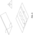
- FIG. 3 illustrates a housing structure with a fold down roof.
- the structure includes three segments, where two of the segments fold down to expose takeoff and landing pads.
- the approximate length of the structure may be 10 m
- the width of the portion with the takeoff and landing pads may be 2.5 m
- the height of the closed housing structure may be 0.7 m.
- the motor may be coupled to a controller and the controller determines when the housing structure needs to be opened (e.g., when a signal from an UAV indicates that a takeoff or landing is imminent, for example, when the UAV is in close proximity to the structure).
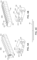
- FIGs. 4A-4C illustrate a modular housing structure.
- the modular housing structure 400A of FIG. 4A includes a plurality of housing segments 401, endcap structures 408, landing pads 403, one or more ingress points 405, and navigational aids 407a-d.
- the individual housing segments 401 are shaped to be mechanically joined together to form an exterior of modular housing structure 400A.
- the housing segments 401 may include geometry to click or slide segments 401 together.
- fasteners e.g., Velcro, zip-ties, magnets, clips, locks, or the like
- one or more landing pads 403 are positioned within individual housing segments 401, and the landing pad 403 is sized for the automated aircraft to land on the landing pad 403.
- the landing pads 403 may be organized with three landing pads 403 evenly spaced on the floor, and two landing pads 403 attached to sidewalls elevated above the floor. Restated, the landing pads 403 may be organized into multiple levels such that some landing pads 403 are vertically above other landing pads 403. Each individual housing segment 401 may have the same layout or may have a different layout of the landing pads 403. If the individual housing segments 401 have the same layout, the landing pads 403 may include a center row of the landing pads 403 disposed below an access corridor. The access corridor extends down the interior of the housing structure 400A. The center row of the landing pads 403 is not covered by other landing pads 403. The access corridor connects to the ingress point 405 and extends past all of the landing pads 403.
- landing pads 403 is only one possible example, and it is anticipated that other layouts and numbers of landing pads 403 may be integrated into each housing segment 401.
- One or more ingress points 405 are shaped to allow passage of the one or more UAVs into the plurality of housing segments 401.
- the ingress point 405 may be a hole in a portion of the housing structure 400A that has a lateral dimension that is larger than the wingspan of the UAVs and a vertical dimension larger than a height of the UAVs.
- the ingress points 405 may be elevated or near the ground.
- ingress point 405 is integrated into the sidewall of an endcap structure 408.
- ingress point 405 may be integrated into a roofing structure.
- the individual housing segments 401 may have a frame of metal polls (e.g., steel, aluminum, etc.), plastic polls, or otherwise.
- the housing segments 401 may also include metal (e.g., steel, aluminum, etc.) or thermal plastic slats (or other similar materials) forming the faces of the housing segments 401 on the frame.
- housing segments 401 may have a metal or plastic frame with metal or plastic slats covering the frame.
- the individual housing segments 401 may include a metal or plastic frame with a canvass or similar material over the frame.
- the individual housing segments 401 may be formed of metal or thermal plastic slats with connections, such as locking hinges, connecting the slats.
- the individual housing segments 401 may have a common structural shape that repeats when assembled to form the modular housing structure 400A.
- a first and last of the housing segments 401 may include endcap structures 408 shaped to enclose an end of the exterior of the modular housing structure 400A.
- the endcap structures 408 may be made of the same materials as the housing segments 401.
- the endcap structure 408 may include or define ingress point 405.
- housing structure 400A includes endcap structures 408 shaped to be mechanically joined to the plurality of housing segments 401, and the endcap structures 408 enclose the ends of the housing structure 400A when the plurality of housing segments 401 are jointed.
- the one or more ingress points 405 are positioned on the endcap structures 408 so the UAVs "fly through" the housing structure 400A to get to their landing pad 403.
- ingress points 405 are referred to as "ingress points” it is appreciated that ingress points may also serve as egress points as well.
- the housing structure 400A may include several navigational aids 407a-d.
- the navigational aids 407a-d may include flashing lights, RFID devices, infrared beacons, sound emitting devices, Bluetooth beacons, fiducial markers and the like.
- Fiducial markers are objects used as optical points of reference and information.
- the fiducial markers may take the form of a mark or set of marks such as a barcode or quick response (“QR”) code.
- the navigational aids 407a-d are displayed on or by the housing structure 400A.
- First navigational aids407a may be positioned proximate to the one or more ingress points 405 to guide the UAVs into the plurality of housing segments 401 (or interior of the housing structure 400A). Similar navigational aids may be placed around the ingress points 405 in the interior of the housing structure 400A to guide the UAVs out of the housing structure 400A.
- the first navigational aids 407a may be associated with and thus indicate an entry location, directions for entry to the housing structure 400A, or some other navigational information or identification information.
- second navigational aids 407b may be placed on or around the one or more landing pads 403 to guide the UAVs onto the one or more landing pads 403.
- the second navigational aids 407b may indicate a landing pad number, directions for landing on the landing pad 403, or other navigational or identification information.
- the second navigational aids 407b may be smaller than the first navigational aids 407a.
- third navigational aids 407c may be placed on an exterior of the housing structure 400A or next to the housing structure 400A.
- the third navigational aids 407c may indicate an identification of the housing structure 400A, an approach path, entry location, housing layout, or other identification or navigational information.
- the navigational aids 407a-c also may reference information stored in a network to which the UAVs are connected or stored onboard the UAVs.
- the third navigational aids 407c may be fiducial markers which include a code for looking up navigational information or layout information of the housing structure 400A.
- the third navigational aids 407c may be larger, brighter or otherwise detectable by the UAVs from a greater distance than the first navigational aids 407a.
- the indoor navigational aids 407d may be fiducial markers indicating an identification of the housing segment 401 or a relative physical position of the housing segment 401 from amongst the plurality of housing segments to aid navigation to a given landing pad 403 within the housing structure 400A.
- the UAVs may be programed to use the indoor navigational aids 407d to find an assigned landing pad 403 in one of the housing segments 401.
- the housing structure 400A may include a plurality of navigational aids407a-c and navigational aids 407d which assist the UAVs in navigating into the housing structure 400A and to the landing pads 403, and also from the landing pads 403 out of the housing structure 400A.
- the third navigational aids 407c are designed to be detected by the UAVs from a great distance to assist the UAV in locating the housing structure 400A.
- the first navigational aids 407a are designed to assist the UAVs in locating and navigating through the ingress points 405 after the UAV has already located the housing structure 400A.
- the first navigational aids 407a are designed to be detected by the UAVs at a closer range and may provide more precise navigational information than the third navigational aids 407c. Accordingly, the first navigational aids 407a may be smaller than the third navigational aids 407c.
- the second navigational aids 407b are designed to guide the UAVs onto the landing pads 403 within the interior of the housing structure 400A.
- the second navigational aids 407b are designed to be detected by the UAVs at a close range and provide precise navigational information. Accordingly, the second navigational aids 407b may be smaller or otherwise detectable by a UAV from a lesser distance than the first navigational aids 407a.
- the indoor navigational aids 407d are designed to provide general navigational information to the UAVs within the interior of the housing structure 400A. Thus, the indoor navigational aids 407d are designed to be detected by the UAVs at close range. If the navigational aids 407a-d are fiducial markers, the indoor navigation aids 407d may be larger than the second navigational aids 407b and smaller than the third navigational aids 407c. Thus, navigational aids407a-d provide a comprehensive visual based navigation system to UAVs.
- Landing pads 403 may include charging circuitry 409 positioned (e.g., integrated into landing pads 403) to supply charge to the one or more UAVs, when the one or more automated aircraft are on landing pads 403. It is appreciated that charging circuitry 409 may include: electrical contacts disposed on the one or more landing pads 403 and positioned to contact electrodes on the one or more UAVs; inductive charging circuitry 409 disposed on the one or more landing pads 403 and positioned to transfer charge inductively to the one or more UAVs; as well as other techniques to provide charge, in accordance with the teachings of the present disclosure.
- FIG. 4B depicts modular housing structure 400B, which has similar features to modular housing structure 400A.
- one or more ingress points 406 are positioned proximate to the top of the individual housing segments 402.
- each of the housing segments 402 may include a separate ingress point 406 to allow passage of the UAVs in or out of the modular housing structure 400B.
- the UAVs may fly in through the "roof" of housing segments 402 and be guided by first navigational aids 407a disposed on the roof.
- the ingress points 406 on the roof of housing segments 402 may be open gaps in the roof of the individual housing segments.
- the individual ingress points 406 in the roofs of the individual housing segments may join together to form a one or more larger ingress points (e.g., a larger strip opening).
- the housing segments 402 of the housing structure 400B may have one less landing pad 403 than the housing segments 401 of housing structure 400A (e.g., housing segments 401 of housing structure 400A have three landing pads 403 evenly spaced on the floor, and two landing pads 403 attached to sidewalls elevated above the floor, whereas housing segments 402 of housing structure 400B are missing the middle landing pad 403 on the floor, which may be so the landing pad 403 does not get wet or receive direct sunlight since the roof of housing structure 400B is partially open). Examples are not limited to these disclosed organizations of the landing pads 403, any organization of the landing pads 403 may be used in the housing structures 400A or 400B.
- Housing structures 400A and 400B may be passive housing structures. Accordingly, housing structures 400A and 400B may not have any communication elements or actively controlled moving parts. If the housing structures 400A and 400B are passive, the UAVs may communicate with a control server via a wireless network (such as a cellular network) in order to know which landing pad 403 to land on and when to take off.
- a wireless network such as a cellular network
- the housing structures 400A and 400B may be active structures with an integrated local communication controller (similar to other communication controllers discussed below).
- the communication controller may communicate with the UAVs to manage which UAVs land on which landing pads 403.
- the communication controller may also actively manage which landing pads 403 receive electric power to charge the UAVs.
- the housing structures 400A and 400B may also include active ingress points 405 with doors. The doors may open and close based on communications from the UAVs and/or a control server requesting the doors to open to allow the UAVs to enter or exit the housing structure 400A or 400B.
- the housing structures 400A and 400B are modular, meaning that the size of the housing structures may be altered by connecting more housing sections 401 or 402 between the endcap structures 408. Similarly, the number of UAVs that the housing structures 400A and 400B may support is scalable by connecting more or fewer housing sections 401 between the endcap structures 408, thus changing the number of landing pads 403 in the housing structure 400A or 400B.
- FIG. 4C illustrates a housing segment 401 (or 402) in a folded, substantially flat configuration.
- the individual housing segments 401 or 402 are foldable into a substantially flat configuration.
- the housing segments 401 may be stacked for easy transportation.
- the housing segments 401 or 402 are erectable into one of the forms shown in FIGs. 4A and 4B and connected to form the housing structures 400A or 400B.
- the frame of the housing segment 401 may include joints, which allow for the housing segments 401 to fold into the substantially flat configuration.
- the connectors between the slats may allow the housing segments 401 to fold into the substantially flat configuration.
- the housing segments 401 may be foldable into a substantially flat configuration without the housing segments 401 being disassembled.
- the landing pads 403 may have to be repositioned or adjusted before the housing segment 401 can be folded into the substantially flat configuration.
- FIG. 5 illustrates a modular housing structure.
- FIG. 5 depicts an 8'x40' module, which may be used with any of the structures disclosed herein. This provides the 8'x40' base structure with five-plus pads, chargers, wiring, IT and optional ventilation prebuilt into a self-contained unit with internal wiring.
- Various retractable tops could be added or the modules could be built into a larger modular structure similar to the "fly in modular" structure proposed in FIGs. 4A and 4B . Since the modules depicted are relatively flat, the modules could stack ⁇ 10 high in a standard container or trailer bed for mobile deployment.
- FIGs. 6A-6C illustrate several examples of single-aircraft housing structures.
- a first example 601 illustrates a fold open roof structure to enclose the UAV, and the UAV is elevated on a pedestal.
- the roof is slightly curved so water may run off.
- the pedestal may include a landing pad as discussed elsewhere herein.
- the second housing structure example 603 has a similar curved roof structure, but the roof may be pulled off, or the sides of the roof may fold under the pedestal to open the top of the roof.
- the third example 605 of the housing structure depicted shows a retractable folding (origami-like-similar to an accordion) roof structure.
- the roof is made from a corrugated sheet of material (e.g., plastic or the like) that folds into a small space when retracted.
- This housing structure may be advantageous because the roof structure can be fabricated from inexpensive materials and is semideformable.
- the roof may be folded back manually or automatically (e.g., the roof is on one or more tracks that cause the roof to retract).
- This single UAV housing structure may have a relatively small footprint (e.g., 4' x 4', which is just slightly larger than the lateral dimensions of a single UAV).
- the housing structure may include a landing pad with charging circuitry and a dedicated power source (e.g., one or more batteries, capacitors, or the like).
- the fourth example 607 of the single UAV housing structure depicted in FIG. 6A-4 illustrates a plastic dome that folds down over the UAV via a hinge on one side.
- the dome may open or close manually or via a motor.
- the dome may have springloaded assistance to reduce stress on the motor. It is appreciated that this example conveys storage advantages, for example, the dome components may be separated from the landing pads and stacked. Moreover, the dome may be made from a transparent polymer or glass in order for operators to see which structures contain an UAV and which are empty.
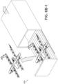
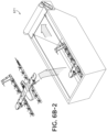
- FIG. 6B illustrates several other examples of single UAV housing structures.
- the first example 609 in FIG. 6B-1 illustrates a housing structure where the landing pad slides out of a box similar to how a shoebox may open. It is appreciated that either the cover or the landing pad may move. This may be achieved by putting the cover or the landing pad on tracks.
- the closed housing structure may be substantially rectangular shaped (e.g., a 1.22 m x 2.44 m (4' x 8') floor plan box).
- the second example 611 in FIG. 6B-2 illustrates a single UAV housing structure similar to that of FIG. 2 , where a rolling cover is used to cover the UAV.
- the sides may be hard while the cover is soft (to permit rolling) or, as stated above in connection with FIG. 2 , the cover may be hard segments linked together with flexible segments similar to hard-top rolling truck bed covers. In other examples, the sides may be soft as well.
- the rolling of the cover may be manual or automatic (e.g., a motor coupled to the spool to roll and unroll the over). Unrolling of the cover may be guided with tension wires and the cover may slide along tracks.
- the housing structure may be 1.22 m x 1.52 m (4' x 5').
- the third example 613 depicted in FIG. 6B-3 illustrates a second origami-type housing structure. Unlike the first origami-style housing structure, the one depicted here does not have a rectangular roof base (the roof base of the example 613 is substantially elliptical).
- the folding roof structure also folds in a direction perpendicular to the length of the landed UAV (whereas in the other folding example, the roof collapses lengthwise relative to the landed UAV).
- the fourth example615 in FIG. 6B-4 illustrates a "lotus flower” inspired housing structure where four transparent (or opaque in some example) roof segments open from a dome shape to reveal the UAV inside.
- the roof structure may be a hard shell made from a plastic or the like. This structure when unfolded may have a large footprint (e.g., 2.13 m x 2.13 m (7' x 7')).
- FIG. 6C illustrates an additional example 617 of an UAV housing structure.
- the housing structure depicted is similar to example 607 of FIG. 6A-4 ; however, the housing structure depicted here is conformal to the shape of the UAV.
- the roof of the housing takes up as little space as possible since it follows the contours of the UAV disposed within.
- FIGs. 7A and 7B illustrate a radial housing structure, in accordance with an example of the disclosure.
- a substantially circular radial cover is positioned to cover all of the landing pads and is held up by a thin metal frame.
- the cover may be soft-top or hardtop.
- the housing structure may be unfolded and assembled like a tent to cover all of the landing pads.
- the cover may open to expose all of the landing pads simultaneously. Alternatively, only part of the cover may open, and the UAV may fly in through this small opening to their respective pad through the use of fiducials or signals within the housing structure.
- the landing pads may be disposed on a rotating platform, where the location that the UAV that is about to take off or land from is rotated to the exposed position.
- the rotating platform may be controlled by a motor, a controller, and communication logic (e.g., radio WiFi or the like) to communicate with incoming and outgoing UAVs and one or more control stations.
- FIG. 8 illustrates a circular housing structure.
- FIG. 8 is similar to FIG. 7 in that a circular housing structure with possible rotating internals is employed.
- the UAVs may land, and then a conveyor belt or track of landing pads may be employed to move the UAVs into the housing structure (moving counter clockwise).
- the conveyer belt moves the UAV into the takeoff position.
- the empty charging pad is moved counter clockwise to the landing position to receive an UAV.
- FIG. 9 illustrates "a bottom dealing card deck” housing structure.
- landing pads are deployed from the bottom of the housing structure similar to dealing cards from the bottom of a deck.
- the landing pads may be connected and slide-out of the bottom of the housing structure on a rail or the like.
- One advantage of this structure is that a single actuator may be required to deploy and retract aircraft via a cable.
- the housing structure may have a very small footprint (e.g., 1.52 m x 1.52 m (5' x 5')).
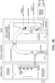
- FIG. 10 illustrates a continuous landing, charging, and taking off housing structure.
- the UAV may land on the landing pad (left), which extends outward from the housing structure.
- the aircraft may then engage a slot/track where the aircraft is carried (or travels under its own power) along the track to a charging location and/or a package loading location.
- the aircraft receives charge through a power rail in the track.
- the depicted example shows a single level housing structure, other examples may have multiple levels.
- the roof may include photovoltaic cells to provide at least some of the power to the aircraft with a power rail or other charging mechanism.
- the housing structure depicted could be mounted on a vehicle.
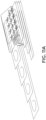
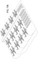
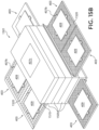
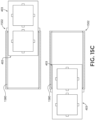
- FIGs. 11A and 11B illustrate a housing with a slot taxi and battery swap gantry.
- the example depicted in FIG. 11A is similar to the example depicted in FIG. 10 ; however, the example depicted in FIG. 11A has multiple levels where the UAVs can land, batteries are exchanged via the gantry, and the UAVs pick up packages.
- FIG. 11B depicts one level of the example depicted in FIG. 11A . In the depicted example, the UAVs land on the terraced landing pads on the left hand side of the page, and take off from the terraced takeoff points on the right hand side of the page.
- the UAVs may reside on charging stations, or have batteries exchanged from the rows of batteries depicted, or the like.
- the UAVs may be guided to the landing pads, or the landing pads may be marked, with visual, electronic, or magnetic aids (e.g. the UAV magnetically clips to the tracks).
- FIGs. 12A-C illustrates a spindle housing.
- the UAVs may land on hoops or another type of landing pad (e.g., the square landing pads depicted elsewhere).
- An arm may extend down to secure and adjust the UAV in position once it has landed.
- the UAV may be able to land in the hoop in just about any orientation, and the arm associated with each hoop may adjust the orientation of the UAV after landing.
- the pads may be able to move up and down (vertically) on the spindle.
- FIG. 13A and 13B illustrate a spindle housing structure. Like the housing structure of FIG. 12A , the housing structure of FIG. 13A shows a spindle with multiple UAVs landing pads. As depicted, the UAV may land on a pad on the rack, and a hollow U-shaped base may hold the UAV in place. A band or the like may be used to hold the UAV in place. Either electrodes or inductive charging may be used to charge the one or more batteries on the UAV.
- the pad may swing to a different side of the spindle to get the UAV away from the landing zone.
- An operator e.g., a human or a robotic arm
- the package may be held to the UAV by the tape due to magnetic force between the tape and UAV.
- FIG. 14 illustrates a landing and takeoff platform.
- a landing pad is positioned at the top of a spindle (e.g., to avoid having the UAV crash into people and things at ground level).
- the landing pad extends down the spindle and then rotates to a charging and package pickup station.
- the charging station may rapidly recharge the UAV, or replace the battery as a package is attached to the underside of the UAV.
- the UAV may take off from the charging positon.
- the empty charging pad may then be returned to the top of the spindle to receive another UAV.
- FIGs. 15B-D illustrate modular housing structures 1500 with retractable charging pads, in accordance with embodiments of the disclosure.
- FIG. 15A illustrates a modular housing structure 1500, which is not part of the scope of the appended claims.
- FIG. 15A depicts a plurality of modular housing sections 1505 stacked with a capping structure 1510 on top to form a modular housing structure 1500, which may be used with any of the structures disclosed herein.
- the modular housing structure 1500 may also include third navigational aids 407c.
- Each of the stacked modular housing sections 1505 may include a landing pad 403, with charging circuitry 409, and second navigational aids 407b.
- the landing pads 403 may also include airflow openings 1520.
- the modular housing structure 1500 includes a base structure 1570.
- the modular housing sections 1505 are stackable such that the modular housing structure 1500 supports a scalable number of the UAVs based on a number of modular housing sections 1505 vertically stacked on each other at a time. Restated, the modular housing sections 1505 are stackable on each other to form a modular housing structure 1500. Any number of modular housing sections 1505 may be stacked.
- the landing pads 403 may be mechanically actuated to extend from an interior of a given modular housing section 1505 to receive and deploy the UAV and withdraw or retract into the interior to shelter the UAV from weather.
- the individual modular housing section 1505 may have a door 1508 which opens when the landing pad is mechanically actuated to extend from the interior of the modular housing section 1505, and closes when the landing pad is mechanically actuated to withdraw into the interior of the modular housing section 1505.
- the door 1508 may be attached to the landing pad 403 such that when the landing pad 403 is mechanically actuated the door moves with the landing pad 403.
- the door 1508 may fold down when the landing pad 403 is extended from the interior of the modular housing section 1505 or may remain upright.
- the landing pads 403 may be actuated by an electric motor (not shown).
- Each modular housing section 1505 may have an electric motor.
- the modular housing structure 1500 may have an electric motor with mechanical energy transfer mechanisms (such as chains, gears, drive rods, etc.) connected to each of the modular housing sections 1505.
- the landing pads 403 may extend in any direction from the modular housing structure 1500.
- a first portion of the modular housing sections 1505 may actuate the landing pad 403 out a first side of the modular housing structure 1500 and a second portion of the modular housing sections 1505 may actuate the landing pad 403 out a second side of the modular housing structure 1500 different from the first side.
- the landing pads 403 In some locations, such as on an open rooftop, it may be useful to have the landing pads 403 extend in all directions from the modular housing structure 1500 to increase the number of UAVs that may enter and exit the modular housing structure 1500 at any given time from different approach angles. In other environments, such as near a wall or other obstacle, it may be advantageous to have the landing pads 403 only extend in one or two directions to avoid the obstacles or more efficiently use limited space.
- an exterior of the modular housing section 1505 along with the door may enclose a UAV on the landing pad 403 to protect the UAV from weather or from being stolen.
- the modular housing structure 1500 may enclose and protect the landing pad 403 and a UAV on the landing pad 403 when the landing pad 403 is within the interior of the modular housing section 1505.
- the airflow openings 1520 in the landing pads 403 may come in several forms.
- the landing pad 403 may include portions of a grating or a mesh that define the airflow openings 1520 between the grating or mesh material.
- the airflow openings 1520 may be holes in the landing pad 403.
- the airflow openings 1520 may be gaps or ducting between the landing pad 403 and the sidewall structure of the modular housing sections 1505.
- the depicted embodiment is a case where charging pads may slide-out from the sides of the structure on tracks.
- the UAVs are pulled into the housing structure 1500 for safe storage.
- the landing pads 403 may slide-out of the modular housing structure 1505 in response to an UAV landing or departure being requested from either the UAV or a control server.
- the electronics to communicate with the UAV and extend and retract the pads may be enclosed in the modular housing structure 1500.
- the base structure 1570 may encase the bottom side of the lower most of the modular housing sections 1505.
- the base structure 1570 may serve as a stable platform for the modular housing structure 1500.
- the base structure may also act to prevent moisture from entering and the climate controlled air from leaving the modular housing structure 1500.
- FIG. 15B illustrates a modular housing structure 1501 similar to the modular housing structure 1500 of FIG. 15A , except that the modular housing structure 1501 has two landing pads 403 side by side within each modular housing section 1505.
- the landing pads 403 are arranged in a 2x1 pattern.
- other patterns are also possible, such as 2x2 or 3x1.
- the landing pads 403 which are side by side when in an interior of the modular housing section 1505 are connected such that the landing pads 403 are mechanically actuated together.
- FIG. 15C illustrates a modular housing structure 1502 similar to the modular housing structure 1501 of FIG. 15B .
- the side-by-side landing pads 403 are on a track 1580 which runs perpendicular to the direction in which the landing pads 403 are side by side.
- the side-by-side landing pads 403 are connected such that the landing pads 403 are mechanically actuated together in the direction perpendicular to the direction in which the landing pads 403 are side by side.
- FIG. 15D illustrates the interior of the modular housing structure 1503 and also the airflow within the modular housing structure 1503.
- Modular housing structure 1503 represents one possible interior implementation of modular housing structures 1500, 1501 or 1502.
- the modular housing structure 1503 includes a climate controller 1550, a communication controller 1560, and optionally a battery 1530 in the capping structure 1510. These elements may alternatively be placed in the base structure 1570.
- the battery may be replaced by a connection to an outside power source such as an electrical grid, a generator, or another electric power source.
- the interior of the modular housing structure 1503 may also include landing pads 403 which define airflow openings 1520.
- the climate controller 1550 may include at least one of a heater, a fan, an air conditioning unit, or a dehumidifier.
- the climate controller 1550 may control the air temperature using the heater and air conditioning unit.
- the climate controller 1550 may control the humidity within the modular housing structure 1503 using the dehumidifier.
- the fan may assist the heater, air conditioning unit and dehumidifier in controlling the climate throughout the modular housing structure 1503 by circulating the air within the modular housing structure. Accordingly, the climate controller 1550 may keep the UAVs operational by preventing the UAVs from having overheating, icing, or other climate related problems.
- the airflow openings 1520 allow the climate controller 1550 to more easily control the climate within the interior of the modular housing structure 1500 by allowing air to flow from the climate controller 1550 to each of the modular housing segments 1505.
- the structure of the modular housing structure 1503 may also shelter the UAVs from wind, rain, snow, etc. and keep the climate controlled within the modular housing structure 1503. In this way, the modular housing structure 1503 may shelter the UAVs in the interior of the modular housing structure 1503 from weather and efficiently control the climate in the modular housing structure 1503.
- the modular housing structures of FIGs. 15A-D are active housing structures that may communicate with the UAVs directly or indirectly.
- the housing structure may use Wi-Fi or another Wireless Local Area Network ("WLAN") to communicate with the UAVs to facilitate the landing and storage of the UAVs in the modular housing structure.
- the modular housing structure may communicate via a control server over a wireless network to which the UAVs are connected. Restated, the UAVs or a control server may communicate with the modular housing structure (directly or indirectly) in order to request mechanical actuation of the landing pads 403 to facilitate landing or take off for the UAVs.
- Wi-Fi Wireless Local Area Network
- WLAN Wireless Local Area Network
- the communication controller 1560 may communicate with the UAVs and control the operations of the modular housing structure 1503.
- the communication controller 1560 may communicate with the UAV directly or indirectly.
- the communication controller 1560 may operate based on its communications with the UAV or may operate based on commands from a control server. For example, the communication controller 1560 may communicate with the UAV to determine that the UAV requesting to be stored in the modular housing structure 1503.
- the communication controller 1560 may assign the UAV to one of the landing pads 403 and then cause the assigned landing pad 403 to be mechanically actuated to the exterior of the modular housing structure 1503. Once the communication controller 1560 senses that the UAV has landed on the landing pad 403 (such as by sensing that charging has commenced or by a detected change in weight of the landing pad), the communication controller 1560 may then cause the landing pad 403 to be mechanically actuated to an interior of the modular housing structure 1503. Alternatively, the communication controller 1560 may mechanically actuate the landing pad to an interior of the modular housing structure 1503 based on a communication form the UAV that the UAV has landed.
- the communication controller 1560 may receive a communication from the communication server indicating that a UAV stored in modular housing structure 1503 is to take off and the communication controller 1560 may cause the associated landing pad 403 to be mechanically actuated to an exterior of the modular housing structure 1503 such that the UAV may take off.
- the communications controller 1560 may control an electric motor in order to mechanically actuate the landing pad 403.
- the communication controller 1560 may also control the climate controller 1550 to control the climate in the modular housing structure 1500 to cool or heat the UAV based on a sensed temperature of the UAV, a communication from the UAV indicating a temperature of the UAV, or received weather information.
- the communication controller 1560 may receive weather information from the control server that the weather is below freezing and snowing and based on this weather information control the climate controller 1550 to deice a recently arrived UAV.
- Photovoltaic devices may be disposed on the top of the structure to charge the UAVs contained within. Additionally, the battery 1530 may store power from the photovoltaic device.
- the communication controller 1560 may include communication electronics for communicating via Wi-Fi, radio, RFID, Bluetooth, or the like.
- FIGs. 16A-16C illustrate rotating charging pads in a housing structure.
- FIG. 16A shows a large rectangular receptacle 1601 with a plurality of landing pads 1603 disposed within which are sized and spaced to hold UAVs.
- rectangular receptacle 1601 has an opening 1605 in the top where UAVs can land and takeoff from.
- track 1621 is at least partially disposed within an interior of receptacle 1601.
- Motor 1623 is mechanically coupled to move one or more landing pads 1603 along track 1621 from inside receptacle 1601 to a takeoff and landing position (top), where the one or more UAVs land on the one or more landing pads 1603 from the takeoff and landing position.
- one or more landing pads 1603 are configured to mechanically couple to track 1621, to move one or more landing pads 1603 along the track.
- landing pads 1603 may include clasps to grasp onto a cable or chain (e.g., a tow line).
- Motor 1623 may be mechanically coupled to move the towline.
- FIG. 16B depicts another example of the housing structure.
- the housing structure in FIG. 16B has many of the same components as the housing structure in FIG.16A .
- the structure in FIG. 16B includes a bypass structure 1625 disposed within receptacle 1601, where bypass structure 1625 is positioned along the track 1621 to prevent individual landing pads 1603 in the plurality of landing pads 1603 from being moved into the takeoff and landing position (top), when the one or more landing pads 1603 are moved along the track 1621.
- the bypass structure may redirect pads from making it to the takeoff and landing position. This way pads with a UAV on them do not get moved into the takeoff position when an UAV is landing.
- the bypass system may route the landing pad onto a secondary track (similar to a train).
- track 1621 is one of a plurality of tracks at least partially disposed within an interior of receptacle 1601.
- the landing pad may clip onto another cable to be pulled onto the secondary track.
- This functionality may be governed by a controller (e.g., controller 1631) that is informed by other components when UAVs need to land/takeoff.
- the controller including logic that when executed by the controller causes the controller to perform operations including determining if an individual landing pad 1603 in the plurality of landing pads 1603 is occupied by the one or more automated aircraft. Then, based on determining if the individual landing pad 1603 is occupied, the controller may use the bypass structure 1625 to prevent the individual landing pad from being moved into the takeoff and landing position.
- FIG. 16C illustrates the interior of a housing structure, like the other examples, individual landing pads 1603 are coupled to be moved on a track 1621 by motor 1623.
- Motor 1623 is coupled to controller 1631, communication system 1633 (e.g., to receive wired or wireless communication form the internet, radio sources or the like), and power supply 1635.
- Controller 1631 is also electrically coupled to thermostat/thermometer 1627.
- Thermostat 1627 is positioned to measure a temperature of the interior of the receptacle 1601.
- Heating system 1641 e.g., a thermoelectric heater, resistive heater or the like
- Cooling system 1643 e.g., thermoelectric cooler
- thermostat 1627 In response to thermostat 1627 measuring a first temperature that is greater than a first threshold temperature (e.g., >40 °C), thermostat 1627 activates cooling system 1643, and in response to thermostat 1627 measuring a second temperature that is less than a second threshold temperature (e.g., ⁇ 5°C), thermostat 1627 activates heating system 1641. This may keep UAVs electronics from overheating/cooling.
- a first threshold temperature e.g., >40 °C
- thermostat 1627 In response to thermostat 1627 measuring a first temperature that is greater than a first threshold temperature (e.g., >40 °C), thermostat 1627 activates cooling system 1643, and in response to thermostat 1627 measuring a second temperature that is less than a second threshold temperature (e.g., ⁇ 5°C), thermostat 1627 activates heating system 1641. This may keep UAVs electronics from overheating/cooling.
- FIG. 17 illustrates a static wire charging station.
- one or more UAVs may land or be placed on charged wires strung between posts within the body of the housing structure.
- the UAVs have conductive hooks to engage the wires (to charge the batteries) and hold the UAV in place.
- the roof of the housing structure may be a retractable awning made from fabric, plastic, or the like. Charging of the UAVs on the wires may be achieved with 24V DC power supply.
- 1-4 aircraft may hang from wires in an 8' housing structure.
- a single 115 V AC outlet may be provided for charging, awning extension/retraction, infrared navigation, and communication with the UAV.
- FIG. 18 illustrates a warehouse-based unmanned aerial vehicle (UAV) "nest".
- the warehouse based housing structure may have fly-in UAV functionality (e.g., through an opening in the building or the like).
- Guidance systems described in association with other examples disclosed herein, may be used for UAVs to navigate into the building. After entering, the UAVs may be placed on a track or conveyor belt where some are diverted to storage, charging stations, or maintenance, and others (if they still have sufficient charge to complete a delivery) are rerouted to package pickup.
- the warehouse is divided into three sections, a first section for UAV landing, a second section for UAV package loading and departure, and a third section for package prep (e.g., food prep if the package contains food).
- Prepared packages may be placed on a conveyor belt or track and moved to the UAV loading/departure zone. After the UAV is loaded, it may leave through one or more holes in the housing structure.
- the one or more holes/windows in the structure may have doors that are automated to open/close with an UAV departure or landing.
- the housing structure may include advanced computer systems (e.g., processors, memory, power supplies, and the like) to control the large number of UAVs flowing in and out of the warehouse.
- the computer may communicate with incoming UAV to determine the charge level of the battery and assign the UAV a mission based on the charge level.
- the conveyor system may similarly be controlled with one or more computer systems coupled to motors and the like.
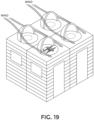
- FIG. 19 illustrates wind reduction housing structures.
- the housing structure roofs are shells that are substantially quarter-spherical.
- the shells have landing pads disposed at least in part under the roof of the structure.
- the roof of the structure rotates (either passively or with controlled motorization) to block the UAVs from the wind. This way UAVs do not blow away while on the landing pads.
- the landing pads may be intermediary landing pads disposed on the top of a building or the like. This way if a mission end point is very far away (outside the maximum range of the UAV) the UAV can stop to charge at a midpoint or on its way back from completing a mission.
- the area under the shelter could be an ingress point into a housing structure (e.g., the building depicted here).
- a housing structure e.g., the building depicted here.
- FIGs. 20A and 20B illustrate systems for automated aircraft handling and storage.
- FIG. 20A illustrates UAVs may land on the rectangular pads. Then robotic arms may be used to pick up the UAVs and put them in high-density charging and/or storage. Similarly, when an UAV is ready to complete a mission, the robotic arm may be used to place the UAV on the landing pad from storage shelves. After the robotic arm disengages from the UAV, the UAV may take off and complete its mission.
- the robotic arms may be coupled to a computer system, and move their position according to the takeoff and landing patterns of the UAVs. For example, incoming UAVs may communicate with the computer system controlling the robotic arms, to inform the arms to move out of the way of an incoming UAV, or to take an UAV out of its storage shelf because a mission was requested.
- FIG. 20B also illustrates a system 2000 for UAV handling and storage.
- the illustrated example of system 2000 includes a storage body 2050, storage racks 2030, a robotic arm 2010 on a track 2015, a surface 2040 with landing pads 2020, and a controller 2018.
- the robotic arm 2010 is controlled by the controller 2018.
- the controller 2018 may be a computer, CPU, processor, or other control circuitry.
- the controller 2018 controls the robotic arm 2010 to move the UAVs from a landing pad 2020 to the storage racks 2030 and from the storage racks 2030 to a landing pad 2020.
- the storage body 2050 may be a framed box about the size of a storage container and capable of being loaded on a semi-truck trailer, or may be mounted to a vehicle.
- the surface 2040 may be a slat capable of folding up onto the open side of the storage body 2050 for transportation.
- the robotic arm 2010 may be fixed or move along the track 2015.
- the robotic arm 2010 is attached to the storage body 2050, and the arm can traverse vertically along a vertical beam of the robotic arm and also horizontally on the track 2015 to move in the x/y plane. This movement functionality allows the arm to place/remove the UAVs from their designated storage area in the storage body 2050.
- system 2000 may include navigational aids 407a-c similar to those described above to guide the UAVs to the landing pads 2020.
- the storage racks 2030 may include charging circuitry 409 (not shown here) and mounts for securing the UAVs for transport while stored in the storage racks 2030.
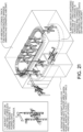
- FIG. 21 illustrates a high-density wire charging housing.
- UAVs land on a cable, and are pushed onto an available hanger within the housing structure.
- the UAVs are hung like clothes on hangers.
- aircraft arriving and departing can be managed.
- the aircraft may be moved within the housing structure along a track similar to a clothes rack at a drycleaners.
- the UAVs drop their batteries into one of two charging carousels.
- the charging carousel is indexed and charged batteries are uploaded into departing aircraft. Departing UAVs enter a location within the housing structure where they are pushed off of the hanger and into a takeoff area. When ready, the UAV is slid off of the rails and a package is uploaded.
- FIGs. 22A and 22B illustrate a housing with slide-out takeoff and landing racks.
- individual racks slide-out independently (e.g., each rack housing an aircraft slides in and out individually).
- the racks may have UAV charging functionality. Their sliding may occur manually (e.g., when an operator wants to access an UAV) and/or automatically (e.g., when an UAV needs to take off or land).
- all of the racks may slide-out at once to expose all of the aircraft.
- the housing structure may be terraced (e.g., similar to bleacher seats) so all UAVs may take off or land at once (e.g., in high volume situations).
- FIGs. 23A and 23B illustrate a housing structure with a turntable and gantry.
- the UAVs may land on the top of the housing structure.
- the UAVs may be in any number of orientations due to landing conditions (e.g., wind blowing the UAVs off course).
- the turntable may be coupled to logic to turn the aircraft to a positon so it can be picked up by a mechanical arm/gantry coupled to the housing structure, and the mechanical arm puts the UAV in the proper slot for charging and/or storage.
- the arm may be sent instructions to pick up the aircraft and a battery pack and put it in a takeoff position on the turntable on top of the housing structure.
- the arm may be coupled to any number of actuators, sensors, and computer systems to enable this functionality.
- FIGs. 24A and 24B illustrate a takeoff and landing pad with manual battery swap.
- an UAV lands on the roof of a structure and a worker in the structure supplies the UAV with a package and additional power (e.g., battery swap).
- the UAV may land on tracks or a conveyor belt, which move the UAV across the top of the structure to allow the worker to attach a parcel and change the battery or perform other maintenance.
- FIG. 25 illustrates a mobile charging station with swing-out landing pads.
- the depicted example shows a spindle with a plurality of landing pads attached to the spindle, and the landing pads are coupled to the spindle to swing inward towards the cab of the truck.
- part of the truck has been converted to include an operator system.
- the operator may attach/remove batteries and packages from the UAVs.
- UAVs may land on the landing pads when the landing pad is extended away from the cab of the truck. Once the UAV is landed and secured, the landing pads may be rotated in towards the truck to receive a new package. When the UAV is ready to be deployed, it may once again be rotated out away from the truck cab.
- FIGs. 26A-26E illustrate mobile charging stations.
- FIGs. 26A and 26B illustrate an extendable, mobile charging station 2600.
- the extendable, mobile charging station 2600 includes a main body 2640 and an extendable portion 2645.
- the main body 2640 and extendable portion 2645 may be mounted on a vehicle 2670 such as a trailer of a semi-truck or on any type of vehicle.
- the main body 2640 and extendable portion 2645 may be made of steel, aluminum, thermal plastic or otherwise.
- the extendable portion 2645 may move on tracks or other similar mechanisms.
- the extendable, mobile charging station 2600 may also include an ingress point 2620 and first navigational aids 407a proximate to the ingress point 2620.
- the ingress point 2620 may be defined by the main body 2640 as shown in FIG. 26B . However, the ingress point may also be located at any point on the main body 2640 or extendable portion 2645, including the top, sides, or ends (illustrated).
- the extendable portion 2645 may extend from the main body 2640.
- the ingress point 2620 may be opened by the extendable portion 2645 extending, or may include a door or other mechanism for closing and opening the ingress point.
- the ingress point 2620 may be sized to allow UAVs to pass through the ingress point into or out of an interior of the extendable, mobile charging station 2600.
- FIG. 26C is an aerial view of the extendable, mobile charging station 2600 with a view through its roof.
- the extendable, mobile charging station 2600 may also include a generator 2610 and a plurality of landing pads 403 within the interior of the extendable, mobile charging station 2600.
- the landing pads 403 may include charging circuitry 409 and second navigational aids 407b similar to those discussed with relation to other examples.
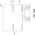
- FIG. 26D is a view of the extendable, mobile charging station 2600 from the rear of the vehicle looking through the rear wall of the extendable, mobile charging station 2600.
- the extendable, mobile charging station 2600 may include multiple levels of landing pads 403 such that some of the landing pads 403 are vertically above others of the landing pads 403.
- the landing pads 403 may include charging circuitry 409.
- the interior and exterior of the extendable, mobile charging station 2600 may include navigational aids 407a-c to guide the UAVs into the interior of the extendable, mobile charging station 2600 and to the landing pads 403.
- Some of the landing pads 403 may move with the extendable portion 2645 when the extendable portion 2645 is extended. Thus, an aisle for the UAVs to move through may be opened up between the landing pads 403 when the extendable portion 2645 is extended. Restated, the landing pads 403 attached to the extendable portion 2645 may be too close to the landing pads connected to the main body 2640 for the UAVs to pass between when the extendable portion 2645 is not extended. By moving the extendable portion 2645 to the extended position, the landing pads 403 separate such that the UAVs may pass between the landing pads 403 to descend or ascend to a different level of landing pads 403.
- FIG. 26E is an alternative example of the mobile charging station 2600'.
- the mobile charging station 2600' may not be extendable and may include modular housing structures 1500 (or 1501, 1502, 1503) as depicted in FIGs. 15A-D .
- the UAVs may enter and leave an interior of the mobile charging station 2600' by an ingress point 2620'.
- the mobile charging station 2600' may also include a generator 2610 and a communication controller 2650 for communicating with the UAVs either directly or indirectly.
- the communication controller 2650 may communicate with the communication controllers 1560 in the modular housing structures 1500 to control the storage of the UAVs.
- all of the mobile housing structures depicted herein may include a computer, generator 2610 (or other power source), and communication controller 2650 to communicate with the UAVs, perform mechanical operations, or the like.
- FIG. 27 illustrates a housing structure with manual battery swap and storage.
- the housing structure includes battery charging stations and UAVS storage.
- the housing structure is manned.
- the UAVS may fly up to one open window and the operator replaces the battery, attaches a package, or takes the UAVs in for service, or the like.
- the operator may put the UAV on a launch pad out a second window.
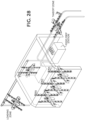
- FIG. 28 illustrates a housing structure with partially automated battery swap and storage.
- part of the UAVs throughput process is automated.
- the UAVs may land on wires or bars, which convey the UAVs into the kiosk.
- An operator may change batteries or put UAVs on a charging rack or remove them for maintenance.
- the operator may load a package and put the aircraft onto a wire where it is conveyed via pulleys to a takeoff area (left).
- the aircraft can takeoff directly from the wires, once the operator enters an "all clear" signal into a computer system (which may include pressing a button) to indicate the operator, and other objects, are clear of the UAVs.
- a computer system which may include pressing a button
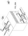
- FIGs. 29A and 29B illustrate slide-out cabinets for manual battery swap and storage.
- a landing pad can be extended outward from the top of the cabinet.
- the UAVs can then be manually or automatically placed from the top into storage in the interior.
- the storage also includes a plurality of batteries that can be changed in and out of the UAVs.
- the housing structure depicted may be plugged into a power source to charge the batteries and the UAVs contained within.
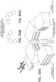
- FIG. 30A-C illustrates another example of slide-out cabinets for manual battery swap and storage.
- the housing depicted in FIG. 30A is similar to the housing depicted in FIG. 29A but the slide-out landing pad configuration is different. Landing pads extend out of the backs of the cabinets, which slide into the cabinets for storage. The sliding may be manual or automatic.
- a tangible non-transitory machine-readable storage medium includes any mechanism that provides (i.e., stores) information in a form accessible by a machine (e.g., a computer, network device, personal digital assistant, manufacturing tool, any device with a set of one or more processors, etc.).
- a machine-readable storage medium includes recordable/non-recordable media (e.g., read only memory (ROM), random access memory (RAM), magnetic disk storage media, optical storage media, flash memory devices, etc.).
Landscapes
- Engineering & Computer Science (AREA)
- Aviation & Aerospace Engineering (AREA)
- Remote Sensing (AREA)
- Transportation (AREA)
- Architecture (AREA)
- Physics & Mathematics (AREA)
- General Physics & Mathematics (AREA)
- Mechanical Engineering (AREA)
- Combustion & Propulsion (AREA)
- Chemical & Material Sciences (AREA)
- Structural Engineering (AREA)
- Civil Engineering (AREA)
- Power Engineering (AREA)
- Robotics (AREA)
- Charge And Discharge Circuits For Batteries Or The Like (AREA)
- Handcart (AREA)
Description
- The current disclosure relates to different housing structures for unmanned aerial vehicles ("UAVs"). UAVs may be powered by rechargeable batteries. When UAVs are not in use they may be stored and the rechargeable batteries may be recharged. Further, UAVs may need waystations to recharge in the middle of longer flights or may need shelter from inclement weather.
-
WO 2017/ 029611 A1 discloses a UAV storage box. The UAV storage box includes a communication module, a plurality of UAV hangar modules, and a power storage module. - Non-limiting and non-exhaustive examples are described with reference to the following figures, wherein like reference numerals refer to like parts throughout the various views unless otherwise specified. The drawings are not necessarily to scale, emphasis instead being placed upon illustrating the principles being described.
-
Claim 1 relates to a modular housing structure with a landing pad mechanically actuated to extend from an interior of a modular housing section to receive and deploy a UAV and withdraw into the interior.FIGs. 15A-D illustrate modular housing structures with retractable charging pads.FIGs. 15B-D illustrate modular housing structures with retractable charging pads according to the scope of the appended claims. -
FIGs. 4A-4C illustrate a modular housing structure with navigational aids, which are also depicted inFigure 15A and15B . - Other aspects of the disclosure are described with reference to the following Figures, which may be useful for understanding the subject matter defined by
claim 1 , but which are not part of the scope of the appended claims. -
FIG. 1 illustrates a housing structure with a telescoping roof. -
FIG. 2 illustrates a housing structure with a retractable (roll-up) cover. -
FIG. 3 illustrates a housing structure with a fold down roof. - FIGs. 5A-E illustrate a modular housing structure.
-
FIGs. 6A-1 to 6A-4 ,6B-1 to 6B-4 , and6C illustrate several examples of single-aircraft housing structures. -
FIG. 7A and 7B illustrates a radial housing structure. -
FIG. 8 illustrates a circular housing structure. -
FIG. 9 illustrates "a bottom dealing card deck" housing structure. -
FIG. 10 illustrates a continuous landing, charging, and taking off housing structure. -
FIGs. 11A and11B illustrate a housing with a slot taxi and battery swap gantry. -
FIGs. 12A-C illustrate a spindle housing structure. -
FIGs. 13A and 13B illustrate a spindle housing structure. -
FIG. 14 illustrates a landing and takeoff platform. -
FIGs. 16A-16C illustrate rotating charging pads in a housing structure. -
FIG. 17 illustrates a static wire charging station. -
FIG. 18 illustrates a warehouse-based automated aircraft "nest. -
FIG. 19 illustrates wind reduction housing and landing structures. -
FIGs. 20A and20B illustrate systems for automated aircraft handling and storage. -
FIG. 21 illustrates a high-density wire charging housing. -
FIGs. 22A and22B illustrate a housing with slide-out takeoff and landing racks. -
FIGs. 23A and23B illustrate a housing structure with a turntable. -
FIGs. 24A and 24B illustrate a takeoff and landing pad with manual battery swap. -
FIG. 25 illustrates a mobile charging station with swing-out landing pads. -
FIGs. 26A-26E illustrate mobile charging stations. -
FIG. 27 illustrates a housing structure with manual battery swap and storage. -
FIG. 28 illustrates a housing structure with partially automated battery swap and storage. -
FIGs. 29A and29B illustrate slide-out cabinets for manual battery swap and storage. -
FIGs. 30A-C illustrate another example of slide-out cabinets for manual battery swap and storage. - Apparatuses, systems, and methods for automated aircraft housing are described herein. In the following description, numerous specific details are set forth to provide a thorough understanding of the apparatuses, systems, and methods. One skilled in the relevant art will recognize, however, that the techniques described herein can be practiced without one or more of the specific details, or with other methods, components, materials, etc. In other instances, well-known structures, materials, or operations are not shown or described in detail to avoid obscuring certain aspects.
- Reference throughout this specification to "one embodiment" or "an embodiment" means that a particular feature, structure, or characteristic described in connection with the embodiment is included in at least one embodiment of the present invention. Thus, the appearances of the phrases "in one embodiment" or "in an embodiment" in various places throughout this specification are not necessarily all referring to the same embodiment. Furthermore, the particular features, structures, or characteristics may be combined in any suitable manner in one or more embodiments.
- Several examples of housings for unmanned aerial vehicles ("UAVs") are described herein. UAVs may also be called automated aircraft ("AA"), automated remote-controlled aircraft, drones, or automated planes.
- The individual examples of housings for the UAVs may provide at least one of charging functions for the UAVs, shelter from weather for the UAVs, and storage of the UAVs when the UAVs are not in use. The housings may be passive or active. The active housings may communicate directly or indirectly with the UAVs and may move component parts of the housing to accommodate the UAVs. In various examples, the housing are modular for easy deployment and storage of a variable number of UAVs.
-
FIG. 1 illustrates a housing structure with a telescoping roof. As shown, the telescoping roof is divided into a plurality of segments, and the segments slide along a track to cover the automated aircraft landing and takeoff pads. As shown, the segments of the telescoping roof are shaped to stack when they are retracted. Like other examples depicted and described herein, the landing pads are coupled to a power supply (see, e.g., blocks on power line depicted) to charge the UAVs when the UAVs land on the pads. The charging may be direct (e.g., with linear electrodes shown) or inductive. The roof segments depicted may have wheels that slide along the track to extend the housing over the landing pads. In another example, other structures such as cables or chains may be used to extend the roof segments over the landing pads. - In the depicted example the substantially triangular roof segments may be covered with photovoltaic cells to provide power. The power generated may be stored (e.g., in a battery, capacitor, or the like) and then supplied to the automated aircraft via power supply circuitry to supply the proper voltage/current.
-
FIG. 2 illustrates a housing structure with a retractable (roll-up) cover. The roof structure depicted may slide over the landing pads similar to how an automated pool cover extends over the surface of a pool: the cover may slide along tracks and unroll off of a spool. Here, the housing cover may be made from fabric, polymers, or other flexible materials. Alternatively or additionally, the cover could include rigid segments connected by flexible/pivoting segments (e.g., similar to a roll-up truck bed cover). The landing and takeoff pads may be disposed in a receptacle (e.g., a crate or the like) that the cover extends over. -
FIG. 3 illustrates a housing structure with a fold down roof. As shown, the structure includes three segments, where two of the segments fold down to expose takeoff and landing pads. As shown, the approximate length of the structure may be 10 m, the width of the portion with the takeoff and landing pads may be 2.5 m, and the height of the closed housing structure may be 0.7 m. It is appreciated that the structure may be opened and closed with a motor. The motor may be coupled to a controller and the controller determines when the housing structure needs to be opened (e.g., when a signal from an UAV indicates that a takeoff or landing is imminent, for example, when the UAV is in close proximity to the structure). -
FIGs. 4A-4C illustrate a modular housing structure. As depicted, themodular housing structure 400A ofFIG. 4A includes a plurality ofhousing segments 401,endcap structures 408, landingpads 403, one or more ingress points 405, andnavigational aids 407a-d.Theindividual housing segments 401 are shaped to be mechanically joined together to form an exterior ofmodular housing structure 400A. In some examples, thehousing segments 401 may include geometry to click orslide segments 401 together. Alternatively or additionally, fasteners (e.g., Velcro, zip-ties, magnets, clips, locks, or the like) may be used to join andsecure housing segments 401 to one another. As depicted, one ormore landing pads 403 are positioned withinindividual housing segments 401, and thelanding pad 403 is sized for the automated aircraft to land on thelanding pad 403. - The
landing pads 403 may be organized with threelanding pads 403 evenly spaced on the floor, and twolanding pads 403 attached to sidewalls elevated above the floor. Restated, thelanding pads 403 may be organized into multiple levels such that somelanding pads 403 are vertically aboveother landing pads 403. Eachindividual housing segment 401 may have the same layout or may have a different layout of thelanding pads 403. If theindividual housing segments 401 have the same layout, thelanding pads 403 may include a center row of thelanding pads 403 disposed below an access corridor. The access corridor extends down the interior of thehousing structure 400A. The center row of thelanding pads 403 is not covered byother landing pads 403. The access corridor connects to theingress point 405 and extends past all of thelanding pads 403. - The illustrated layout of
landing pads 403 is only one possible example, and it is anticipated that other layouts and numbers oflanding pads 403 may be integrated into eachhousing segment 401. - One or
more ingress points 405 are shaped to allow passage of the one or more UAVs into the plurality ofhousing segments 401. For example, theingress point 405 may be a hole in a portion of thehousing structure 400A that has a lateral dimension that is larger than the wingspan of the UAVs and a vertical dimension larger than a height of the UAVs. The ingress points 405 may be elevated or near the ground. In the example ofFIG. 4A ,ingress point 405 is integrated into the sidewall of anendcap structure 408. In other examples (as illustrated and discussed in relation toFIG. 4B ),ingress point 405 may be integrated into a roofing structure. - The
individual housing segments 401 may have a frame of metal polls (e.g., steel, aluminum, etc.), plastic polls, or otherwise. Thehousing segments 401 may also include metal (e.g., steel, aluminum, etc.) or thermal plastic slats (or other similar materials) forming the faces of thehousing segments 401 on the frame. Restated,housing segments 401 may have a metal or plastic frame with metal or plastic slats covering the frame. Alternatively theindividual housing segments 401 may include a metal or plastic frame with a canvass or similar material over the frame. As another alternative, theindividual housing segments 401 may be formed of metal or thermal plastic slats with connections, such as locking hinges, connecting the slats. - The
individual housing segments 401 may have a common structural shape that repeats when assembled to form themodular housing structure 400A. A first and last of thehousing segments 401 may includeendcap structures 408 shaped to enclose an end of the exterior of themodular housing structure 400A. Theendcap structures 408 may be made of the same materials as thehousing segments 401. Theendcap structure 408 may include or defineingress point 405. - As illustrated,
housing structure 400A includesendcap structures 408 shaped to be mechanically joined to the plurality ofhousing segments 401, and theendcap structures 408 enclose the ends of thehousing structure 400A when the plurality ofhousing segments 401 are jointed. In the depicted example, the one ormore ingress points 405 are positioned on theendcap structures 408 so the UAVs "fly through" thehousing structure 400A to get to theirlanding pad 403. Although ingress points 405 are referred to as "ingress points" it is appreciated that ingress points may also serve as egress points as well. - As illustrated, the
housing structure 400A may include severalnavigational aids 407a-d. Thenavigational aids 407a-d may include flashing lights, RFID devices, infrared beacons, sound emitting devices, Bluetooth beacons, fiducial markers and the like. Fiducial markers are objects used as optical points of reference and information. The fiducial markers may take the form of a mark or set of marks such as a barcode or quick response ("QR") code. - The
navigational aids 407a-d are displayed on or by thehousing structure 400A. First navigational aids407a may be positioned proximate to the one ormore ingress points 405 to guide the UAVs into the plurality of housing segments 401 (or interior of thehousing structure 400A). Similar navigational aids may be placed around the ingress points 405 in the interior of thehousing structure 400A to guide the UAVs out of thehousing structure 400A. The firstnavigational aids 407a may be associated with and thus indicate an entry location, directions for entry to thehousing structure 400A, or some other navigational information or identification information. Similarly, secondnavigational aids 407b may be placed on or around the one ormore landing pads 403 to guide the UAVs onto the one ormore landing pads 403. The secondnavigational aids 407b may indicate a landing pad number, directions for landing on thelanding pad 403, or other navigational or identification information. The secondnavigational aids 407b may be smaller than the firstnavigational aids 407a. - Also third
navigational aids 407c may be placed on an exterior of thehousing structure 400A or next to thehousing structure 400A. The thirdnavigational aids 407c may indicate an identification of thehousing structure 400A, an approach path, entry location, housing layout, or other identification or navigational information. Thenavigational aids 407a-c also may reference information stored in a network to which the UAVs are connected or stored onboard the UAVs. For example, the thirdnavigational aids 407c may be fiducial markers which include a code for looking up navigational information or layout information of thehousing structure 400A. The thirdnavigational aids 407c may be larger, brighter or otherwise detectable by the UAVs from a greater distance than the firstnavigational aids 407a. - In some examples, there may be indoor
navigational aids 407d to direct UAVs to theirrespective landing pads 403. For example, the indoornavigational aids 407d may be fiducial markers indicating an identification of thehousing segment 401 or a relative physical position of thehousing segment 401 from amongst the plurality of housing segments to aid navigation to a givenlanding pad 403 within thehousing structure 400A. The UAVs may be programed to use the indoornavigational aids 407d to find an assignedlanding pad 403 in one of thehousing segments 401. - Restated, the
housing structure 400A may include a plurality of navigational aids407a-c andnavigational aids 407d which assist the UAVs in navigating into thehousing structure 400A and to thelanding pads 403, and also from thelanding pads 403 out of thehousing structure 400A. - The third
navigational aids 407c are designed to be detected by the UAVs from a great distance to assist the UAV in locating thehousing structure 400A. The firstnavigational aids 407a are designed to assist the UAVs in locating and navigating through the ingress points 405 after the UAV has already located thehousing structure 400A. Thus, the firstnavigational aids 407a are designed to be detected by the UAVs at a closer range and may provide more precise navigational information than the thirdnavigational aids 407c. Accordingly, the firstnavigational aids 407a may be smaller than the thirdnavigational aids 407c. - The second
navigational aids 407b are designed to guide the UAVs onto thelanding pads 403 within the interior of thehousing structure 400A. Thus, the secondnavigational aids 407b are designed to be detected by the UAVs at a close range and provide precise navigational information. Accordingly, the secondnavigational aids 407b may be smaller or otherwise detectable by a UAV from a lesser distance than the firstnavigational aids 407a. - The indoor
navigational aids 407d are designed to provide general navigational information to the UAVs within the interior of thehousing structure 400A. Thus, the indoornavigational aids 407d are designed to be detected by the UAVs at close range. If thenavigational aids 407a-d are fiducial markers, the indoor navigation aids 407d may be larger than the secondnavigational aids 407b and smaller than the thirdnavigational aids 407c. Thus, navigational aids407a-d provide a comprehensive visual based navigation system to UAVs. - Landing
pads 403 may include chargingcircuitry 409 positioned (e.g., integrated into landing pads 403) to supply charge to the one or more UAVs, when the one or more automated aircraft are on landingpads 403. It is appreciated that chargingcircuitry 409 may include: electrical contacts disposed on the one ormore landing pads 403 and positioned to contact electrodes on the one or more UAVs;inductive charging circuitry 409 disposed on the one ormore landing pads 403 and positioned to transfer charge inductively to the one or more UAVs; as well as other techniques to provide charge, in accordance with the teachings of the present disclosure. -
FIG. 4B depictsmodular housing structure 400B, which has similar features tomodular housing structure 400A. However, in the depicted example, one ormore ingress points 406 are positioned proximate to the top of theindividual housing segments 402. Thus, each of thehousing segments 402 may include aseparate ingress point 406 to allow passage of the UAVs in or out of themodular housing structure 400B. Accordingly, the UAVs may fly in through the "roof" ofhousing segments 402 and be guided by firstnavigational aids 407a disposed on the roof. The ingress points 406 on the roof ofhousing segments 402 may be open gaps in the roof of the individual housing segments. The individual ingress points 406 in the roofs of the individual housing segments may join together to form a one or more larger ingress points (e.g., a larger strip opening). - As depicted in
FIG. 4B , thehousing segments 402 of thehousing structure 400B may have oneless landing pad 403 than thehousing segments 401 ofhousing structure 400A (e.g.,housing segments 401 ofhousing structure 400A have threelanding pads 403 evenly spaced on the floor, and twolanding pads 403 attached to sidewalls elevated above the floor, whereashousing segments 402 ofhousing structure 400B are missing themiddle landing pad 403 on the floor, which may be so thelanding pad 403 does not get wet or receive direct sunlight since the roof ofhousing structure 400B is partially open). Examples are not limited to these disclosed organizations of thelanding pads 403, any organization of thelanding pads 403 may be used in thehousing structures -
Housing structures housing structures housing structures landing pad 403 to land on and when to take off. - Alternatively, the
housing structures landing pads 403. The communication controller may also actively manage whichlanding pads 403 receive electric power to charge the UAVs. Thehousing structures housing structure - The
housing structures more housing sections endcap structures 408. Similarly, the number of UAVs that thehousing structures fewer housing sections 401 between theendcap structures 408, thus changing the number oflanding pads 403 in thehousing structure -
FIG. 4C illustrates a housing segment 401 (or 402) in a folded, substantially flat configuration. In some examples theindividual housing segments housing segments 401 may be stacked for easy transportation. Thehousing segments FIGs. 4A and 4B and connected to form thehousing structures - The frame of the housing segment 401 (or 402) may include joints, which allow for the
housing segments 401 to fold into the substantially flat configuration. Alternatively, if thehousing structures housing segments 401 to fold into the substantially flat configuration. Restated, thehousing segments 401 may be foldable into a substantially flat configuration without thehousing segments 401 being disassembled. In some examples, thelanding pads 403 may have to be repositioned or adjusted before thehousing segment 401 can be folded into the substantially flat configuration. -
FIG. 5 illustrates a modular housing structure.FIG. 5 depicts an 8'x40' module, which may be used with any of the structures disclosed herein. This provides the 8'x40' base structure with five-plus pads, chargers, wiring, IT and optional ventilation prebuilt into a self-contained unit with internal wiring. Various retractable tops could be added or the modules could be built into a larger modular structure similar to the "fly in modular" structure proposed inFIGs. 4A and 4B . Since the modules depicted are relatively flat, the modules could stack ~10 high in a standard container or trailer bed for mobile deployment. -
FIGs. 6A-6C illustrate several examples of single-aircraft housing structures. As shown inFIG. 6A-1 , a first example 601 illustrates a fold open roof structure to enclose the UAV, and the UAV is elevated on a pedestal. The roof is slightly curved so water may run off. The pedestal may include a landing pad as discussed elsewhere herein. As shown inFIG. 6A-2 , the second housing structure example 603 has a similar curved roof structure, but the roof may be pulled off, or the sides of the roof may fold under the pedestal to open the top of the roof. - As shown in
FIG. 6A-3 , the third example 605 of the housing structure depicted shows a retractable folding (origami-like-similar to an accordion) roof structure. The roof is made from a corrugated sheet of material (e.g., plastic or the like) that folds into a small space when retracted. This housing structure may be advantageous because the roof structure can be fabricated from inexpensive materials and is semideformable. The roof may be folded back manually or automatically (e.g., the roof is on one or more tracks that cause the roof to retract). This single UAV housing structure may have a relatively small footprint (e.g., 4' x 4', which is just slightly larger than the lateral dimensions of a single UAV). As shown inFIG. 6A-4 , the housing structure may include a landing pad with charging circuitry and a dedicated power source (e.g., one or more batteries, capacitors, or the like). - The fourth example 607 of the single UAV housing structure depicted in
FIG. 6A-4 illustrates a plastic dome that folds down over the UAV via a hinge on one side. The dome may open or close manually or via a motor. The dome may have springloaded assistance to reduce stress on the motor. It is appreciated that this example conveys storage advantages, for example, the dome components may be separated from the landing pads and stacked. Moreover, the dome may be made from a transparent polymer or glass in order for operators to see which structures contain an UAV and which are empty. -
FIG. 6B illustrates several other examples of single UAV housing structures. The first example 609 inFIG. 6B-1 illustrates a housing structure where the landing pad slides out of a box similar to how a shoebox may open. It is appreciated that either the cover or the landing pad may move. This may be achieved by putting the cover or the landing pad on tracks. In the depicted example, the closed housing structure may be substantially rectangular shaped (e.g., a 1.22 m x 2.44 m (4' x 8') floor plan box). - The second example 611 in
FIG. 6B-2 illustrates a single UAV housing structure similar to that ofFIG. 2 , where a rolling cover is used to cover the UAV. In the depicted example, the sides may be hard while the cover is soft (to permit rolling) or, as stated above in connection withFIG. 2 , the cover may be hard segments linked together with flexible segments similar to hard-top rolling truck bed covers. In other examples, the sides may be soft as well. The rolling of the cover may be manual or automatic (e.g., a motor coupled to the spool to roll and unroll the over). Unrolling of the cover may be guided with tension wires and the cover may slide along tracks. As depicted, the housing structure may be 1.22 m x 1.52 m (4' x 5'). - The third example 613 depicted in
FIG. 6B-3 illustrates a second origami-type housing structure. Unlike the first origami-style housing structure, the one depicted here does not have a rectangular roof base (the roof base of the example 613 is substantially elliptical). The folding roof structure also folds in a direction perpendicular to the length of the landed UAV (whereas in the other folding example, the roof collapses lengthwise relative to the landed UAV). - The fourth example615 in
FIG. 6B-4 illustrates a "lotus flower" inspired housing structure where four transparent (or opaque in some example) roof segments open from a dome shape to reveal the UAV inside. The roof structure may be a hard shell made from a plastic or the like. This structure when unfolded may have a large footprint (e.g., 2.13 m x 2.13 m (7' x 7')). -
FIG. 6C illustrates an additional example 617 of an UAV housing structure. The housing structure depicted is similar to example 607 ofFIG. 6A-4 ; however, the housing structure depicted here is conformal to the shape of the UAV. Thus the roof of the housing takes up as little space as possible since it follows the contours of the UAV disposed within. -
FIGs. 7A and 7B illustrate a radial housing structure, in accordance with an example of the disclosure. In the depicted example, a substantially circular radial cover is positioned to cover all of the landing pads and is held up by a thin metal frame. The cover may be soft-top or hardtop. In some examples, the housing structure may be unfolded and assembled like a tent to cover all of the landing pads. The cover may open to expose all of the landing pads simultaneously. Alternatively, only part of the cover may open, and the UAV may fly in through this small opening to their respective pad through the use of fiducials or signals within the housing structure. In some examples, the landing pads may be disposed on a rotating platform, where the location that the UAV that is about to take off or land from is rotated to the exposed position. The rotating platform may be controlled by a motor, a controller, and communication logic (e.g., radio WiFi or the like) to communicate with incoming and outgoing UAVs and one or more control stations. -
FIG. 8 illustrates a circular housing structure.FIG. 8 is similar toFIG. 7 in that a circular housing structure with possible rotating internals is employed. However, in the depicted example, the UAVs may land, and then a conveyor belt or track of landing pads may be employed to move the UAVs into the housing structure (moving counter clockwise). When an UAV is schedule to take off, the conveyer belt moves the UAV into the takeoff position. After the UAV takes off, the empty charging pad is moved counter clockwise to the landing position to receive an UAV. -
FIG. 9 illustrates "a bottom dealing card deck" housing structure. In the depicted example, landing pads are deployed from the bottom of the housing structure similar to dealing cards from the bottom of a deck. As shown, the landing pads may be connected and slide-out of the bottom of the housing structure on a rail or the like. One advantage of this structure is that a single actuator may be required to deploy and retract aircraft via a cable. Another advantage is that the housing structure may have a very small footprint (e.g., 1.52 m x 1.52 m (5' x 5')). -
FIG. 10 illustrates a continuous landing, charging, and taking off housing structure. In the depicted example, the UAV may land on the landing pad (left), which extends outward from the housing structure. The aircraft may then engage a slot/track where the aircraft is carried (or travels under its own power) along the track to a charging location and/or a package loading location. In some examples, when the aircraft engages the track, the aircraft receives charge through a power rail in the track. - Although the depicted example shows a single level housing structure, other examples may have multiple levels. Moreover, the roof may include photovoltaic cells to provide at least some of the power to the aircraft with a power rail or other charging mechanism. In some examples, the housing structure depicted could be mounted on a vehicle.
-
FIGs. 11A and11B illustrate a housing with a slot taxi and battery swap gantry. The example depicted inFIG. 11A is similar to the example depicted inFIG. 10 ; however, the example depicted inFIG. 11A has multiple levels where the UAVs can land, batteries are exchanged via the gantry, and the UAVs pick up packages.FIG. 11B depicts one level of the example depicted inFIG. 11A . In the depicted example, the UAVs land on the terraced landing pads on the left hand side of the page, and take off from the terraced takeoff points on the right hand side of the page. As shown, between the takeoff and landing points the UAVs may reside on charging stations, or have batteries exchanged from the rows of batteries depicted, or the like. As in other examples, the UAVs may be guided to the landing pads, or the landing pads may be marked, with visual, electronic, or magnetic aids (e.g. the UAV magnetically clips to the tracks). -
FIGs. 12A-C illustrates a spindle housing. As shown inFIG. 12A , the UAVs may land on hoops or another type of landing pad (e.g., the square landing pads depicted elsewhere). An arm may extend down to secure and adjust the UAV in position once it has landed. In the depicted example inFIGs. 12B and 12C , there are multiple tiers of landing pads, and each tier of pads, and individual pads themselves, may be able to rotate separately. As depicted, the UAV may be able to land in the hoop in just about any orientation, and the arm associated with each hoop may adjust the orientation of the UAV after landing. In some examples, the pads may be able to move up and down (vertically) on the spindle. -
FIG. 13A and 13B illustrate a spindle housing structure. Like the housing structure ofFIG. 12A , the housing structure ofFIG. 13A shows a spindle with multiple UAVs landing pads. As depicted, the UAV may land on a pad on the rack, and a hollow U-shaped base may hold the UAV in place. A band or the like may be used to hold the UAV in place. Either electrodes or inductive charging may be used to charge the one or more batteries on the UAV. - Once the UAV has landed, the pad may swing to a different side of the spindle to get the UAV away from the landing zone. An operator (e.g., a human or a robotic arm) may attach a package (including a magnetic tape) to the underside of the UAV. As shown in
FIG. 13B , the package may be held to the UAV by the tape due to magnetic force between the tape and UAV. For example, there may be electromagnetic coils in or on the UAV that interact with the tape to hold the package in place. After the package is attached to the UAV, the landing pad may be raised and rotated into a launch position for package delivery -
FIG. 14 illustrates a landing and takeoff platform. In the depicted example, a landing pad is positioned at the top of a spindle (e.g., to avoid having the UAV crash into people and things at ground level). Once the UAV lands on the landing pad, the landing pad extends down the spindle and then rotates to a charging and package pickup station. The charging station may rapidly recharge the UAV, or replace the battery as a package is attached to the underside of the UAV. Once the UAV receives the package and is sufficiently charged (e.g., above a threshold charge to complete the delivery), the UAV may take off from the charging positon. The empty charging pad may then be returned to the top of the spindle to receive another UAV. In some examples, there may be a plurality of charging pads per spindle, and as the landing/charging pads descend on the spindle they deliver charge to the UAVs. -
FIGs. 15B-D illustratemodular housing structures 1500 with retractable charging pads, in accordance with embodiments of the disclosure. -
FIG. 15A illustrates amodular housing structure 1500, which is not part of the scope of the appended claims.FIG. 15A depicts a plurality ofmodular housing sections 1505 stacked with acapping structure 1510 on top to form amodular housing structure 1500, which may be used with any of the structures disclosed herein. Themodular housing structure 1500 may also include thirdnavigational aids 407c. Each of the stackedmodular housing sections 1505 may include alanding pad 403, with chargingcircuitry 409, and secondnavigational aids 407b. Thelanding pads 403 may also includeairflow openings 1520. In some example embodiments, themodular housing structure 1500 includes abase structure 1570. - The
modular housing sections 1505 are stackable such that themodular housing structure 1500 supports a scalable number of the UAVs based on a number ofmodular housing sections 1505 vertically stacked on each other at a time. Restated, themodular housing sections 1505 are stackable on each other to form amodular housing structure 1500. Any number ofmodular housing sections 1505 may be stacked. - The
landing pads 403 may be mechanically actuated to extend from an interior of a givenmodular housing section 1505 to receive and deploy the UAV and withdraw or retract into the interior to shelter the UAV from weather. The individualmodular housing section 1505 may have adoor 1508 which opens when the landing pad is mechanically actuated to extend from the interior of themodular housing section 1505, and closes when the landing pad is mechanically actuated to withdraw into the interior of themodular housing section 1505. Alternatively, thedoor 1508 may be attached to thelanding pad 403 such that when thelanding pad 403 is mechanically actuated the door moves with thelanding pad 403. Thedoor 1508 may fold down when thelanding pad 403 is extended from the interior of themodular housing section 1505 or may remain upright. - The
landing pads 403 may be actuated by an electric motor (not shown). Eachmodular housing section 1505 may have an electric motor. Alternatively, themodular housing structure 1500 may have an electric motor with mechanical energy transfer mechanisms (such as chains, gears, drive rods, etc.) connected to each of themodular housing sections 1505. - The
landing pads 403 may extend in any direction from themodular housing structure 1500. A first portion of themodular housing sections 1505 may actuate thelanding pad 403 out a first side of themodular housing structure 1500 and a second portion of themodular housing sections 1505 may actuate thelanding pad 403 out a second side of themodular housing structure 1500 different from the first side. - In some locations, such as on an open rooftop, it may be useful to have the
landing pads 403 extend in all directions from themodular housing structure 1500 to increase the number of UAVs that may enter and exit themodular housing structure 1500 at any given time from different approach angles. In other environments, such as near a wall or other obstacle, it may be advantageous to have thelanding pads 403 only extend in one or two directions to avoid the obstacles or more efficiently use limited space. - When a
landing pad 403 is within the interior of themodular housing section 1505, an exterior of themodular housing section 1505 along with the door may enclose a UAV on thelanding pad 403 to protect the UAV from weather or from being stolen. Restated, themodular housing structure 1500 may enclose and protect thelanding pad 403 and a UAV on thelanding pad 403 when thelanding pad 403 is within the interior of themodular housing section 1505. - The
airflow openings 1520 in thelanding pads 403 may come in several forms. For example, thelanding pad 403 may include portions of a grating or a mesh that define theairflow openings 1520 between the grating or mesh material. Alternatively, theairflow openings 1520 may be holes in thelanding pad 403. As another alternative theairflow openings 1520 may be gaps or ducting between thelanding pad 403 and the sidewall structure of themodular housing sections 1505. - The depicted embodiment is a case where charging pads may slide-out from the sides of the structure on tracks. The UAVs are pulled into the
housing structure 1500 for safe storage. Thelanding pads 403 may slide-out of themodular housing structure 1505 in response to an UAV landing or departure being requested from either the UAV or a control server. As described below, the electronics to communicate with the UAV and extend and retract the pads may be enclosed in themodular housing structure 1500. - The
base structure 1570 may encase the bottom side of the lower most of themodular housing sections 1505. Thebase structure 1570 may serve as a stable platform for themodular housing structure 1500. The base structure may also act to prevent moisture from entering and the climate controlled air from leaving themodular housing structure 1500. -
FIG. 15B illustrates amodular housing structure 1501 similar to themodular housing structure 1500 ofFIG. 15A , except that themodular housing structure 1501 has twolanding pads 403 side by side within eachmodular housing section 1505. In the modular housing structure ofFIG. 15B thelanding pads 403 are arranged in a 2x1 pattern. However, other patterns are also possible, such as 2x2 or 3x1. - The
landing pads 403 which are side by side when in an interior of themodular housing section 1505 are connected such that thelanding pads 403 are mechanically actuated together. -
FIG. 15C illustrates amodular housing structure 1502 similar to themodular housing structure 1501 ofFIG. 15B . InFIG. 15C the side-by-side landing pads 403 are on atrack 1580 which runs perpendicular to the direction in which thelanding pads 403 are side by side. The side-by-side landing pads 403 are connected such that thelanding pads 403 are mechanically actuated together in the direction perpendicular to the direction in which thelanding pads 403 are side by side. -
FIG. 15D illustrates the interior of themodular housing structure 1503 and also the airflow within themodular housing structure 1503.Modular housing structure 1503 represents one possible interior implementation ofmodular housing structures modular housing structure 1503 includes aclimate controller 1550, acommunication controller 1560, and optionally abattery 1530 in thecapping structure 1510. These elements may alternatively be placed in thebase structure 1570. The battery may be replaced by a connection to an outside power source such as an electrical grid, a generator, or another electric power source. The interior of themodular housing structure 1503 may also includelanding pads 403 which defineairflow openings 1520. - The
climate controller 1550 may include at least one of a heater, a fan, an air conditioning unit, or a dehumidifier. Theclimate controller 1550 may control the air temperature using the heater and air conditioning unit. Theclimate controller 1550 may control the humidity within themodular housing structure 1503 using the dehumidifier. The fan may assist the heater, air conditioning unit and dehumidifier in controlling the climate throughout themodular housing structure 1503 by circulating the air within the modular housing structure. Accordingly, theclimate controller 1550 may keep the UAVs operational by preventing the UAVs from having overheating, icing, or other climate related problems. Theairflow openings 1520 allow theclimate controller 1550 to more easily control the climate within the interior of themodular housing structure 1500 by allowing air to flow from theclimate controller 1550 to each of themodular housing segments 1505. - The structure of the
modular housing structure 1503 may also shelter the UAVs from wind, rain, snow, etc. and keep the climate controlled within themodular housing structure 1503. In this way, themodular housing structure 1503 may shelter the UAVs in the interior of themodular housing structure 1503 from weather and efficiently control the climate in themodular housing structure 1503. - The modular housing structures of
FIGs. 15A-D are active housing structures that may communicate with the UAVs directly or indirectly. For example, the housing structure may use Wi-Fi or another Wireless Local Area Network ("WLAN") to communicate with the UAVs to facilitate the landing and storage of the UAVs in the modular housing structure. As another example, the modular housing structure may communicate via a control server over a wireless network to which the UAVs are connected. Restated, the UAVs or a control server may communicate with the modular housing structure (directly or indirectly) in order to request mechanical actuation of thelanding pads 403 to facilitate landing or take off for the UAVs. - The
communication controller 1560 may communicate with the UAVs and control the operations of themodular housing structure 1503. Thecommunication controller 1560 may communicate with the UAV directly or indirectly. Thecommunication controller 1560 may operate based on its communications with the UAV or may operate based on commands from a control server. For example, thecommunication controller 1560 may communicate with the UAV to determine that the UAV requesting to be stored in themodular housing structure 1503. - The
communication controller 1560 may assign the UAV to one of thelanding pads 403 and then cause the assignedlanding pad 403 to be mechanically actuated to the exterior of themodular housing structure 1503. Once thecommunication controller 1560 senses that the UAV has landed on the landing pad 403 (such as by sensing that charging has commenced or by a detected change in weight of the landing pad), thecommunication controller 1560 may then cause thelanding pad 403 to be mechanically actuated to an interior of themodular housing structure 1503. Alternatively, thecommunication controller 1560 may mechanically actuate the landing pad to an interior of themodular housing structure 1503 based on a communication form the UAV that the UAV has landed. As another example, thecommunication controller 1560 may receive a communication from the communication server indicating that a UAV stored inmodular housing structure 1503 is to take off and thecommunication controller 1560 may cause the associatedlanding pad 403 to be mechanically actuated to an exterior of themodular housing structure 1503 such that the UAV may take off. - The
communications controller 1560 may control an electric motor in order to mechanically actuate thelanding pad 403. Thecommunication controller 1560 may also control theclimate controller 1550 to control the climate in themodular housing structure 1500 to cool or heat the UAV based on a sensed temperature of the UAV, a communication from the UAV indicating a temperature of the UAV, or received weather information. For example, thecommunication controller 1560 may receive weather information from the control server that the weather is below freezing and snowing and based on this weather information control theclimate controller 1550 to deice a recently arrived UAV. - Photovoltaic devices may be disposed on the top of the structure to charge the UAVs contained within. Additionally, the
battery 1530 may store power from the photovoltaic device. Thecommunication controller 1560 may include communication electronics for communicating via Wi-Fi, radio, RFID, Bluetooth, or the like. -
FIGs. 16A-16C illustrate rotating charging pads in a housing structure.FIG. 16A shows a largerectangular receptacle 1601 with a plurality oflanding pads 1603 disposed within which are sized and spaced to hold UAVs. As shown,rectangular receptacle 1601 has anopening 1605 in the top where UAVs can land and takeoff from. As shown,track 1621 is at least partially disposed within an interior ofreceptacle 1601.Motor 1623 is mechanically coupled to move one ormore landing pads 1603 alongtrack 1621 from inside receptacle 1601 to a takeoff and landing position (top), where the one or more UAVs land on the one ormore landing pads 1603 from the takeoff and landing position. - In the depicted example, one or
more landing pads 1603 are configured to mechanically couple to track 1621, to move one ormore landing pads 1603 along the track. As shown,landing pads 1603 may include clasps to grasp onto a cable or chain (e.g., a tow line).Motor 1623 may be mechanically coupled to move the towline. -
FIG. 16B depicts another example of the housing structure. The housing structure inFIG. 16B has many of the same components as the housing structure inFIG.16A . However, the structure inFIG. 16B includes abypass structure 1625 disposed withinreceptacle 1601, wherebypass structure 1625 is positioned along thetrack 1621 to preventindividual landing pads 1603 in the plurality oflanding pads 1603 from being moved into the takeoff and landing position (top), when the one ormore landing pads 1603 are moved along thetrack 1621. Put another way, the bypass structure may redirect pads from making it to the takeoff and landing position. This way pads with a UAV on them do not get moved into the takeoff position when an UAV is landing. Further, pads without an UAV on them do not get moved into the takeoff positon when an UAV needs to take off. The bypass system may route the landing pad onto a secondary track (similar to a train). Thus,track 1621 is one of a plurality of tracks at least partially disposed within an interior ofreceptacle 1601. In some examples, the landing pad may clip onto another cable to be pulled onto the secondary track. This functionality may be governed by a controller (e.g., controller 1631) that is informed by other components when UAVs need to land/takeoff. Put another way, the controller including logic that when executed by the controller causes the controller to perform operations including determining if anindividual landing pad 1603 in the plurality oflanding pads 1603 is occupied by the one or more automated aircraft. Then, based on determining if theindividual landing pad 1603 is occupied, the controller may use thebypass structure 1625 to prevent the individual landing pad from being moved into the takeoff and landing position. -
FIG. 16C illustrates the interior of a housing structure, like the other examples,individual landing pads 1603 are coupled to be moved on atrack 1621 bymotor 1623.Motor 1623 is coupled tocontroller 1631, communication system 1633 (e.g., to receive wired or wireless communication form the internet, radio sources or the like), andpower supply 1635. -
Controller 1631 is also electrically coupled to thermostat/thermometer 1627.Thermostat 1627 is positioned to measure a temperature of the interior of thereceptacle 1601. Heating system 1641 (e.g., a thermoelectric heater, resistive heater or the like) is electrically coupled tocontroller 1631 and positioned to supply heat to the interior of thereceptacle 1601. Cooling system 1643 (e.g., thermoelectric cooler) is electrically coupled tocontroller 1631 and posited to remove heat from the interior of thereceptacle 1601. In response tothermostat 1627 measuring a first temperature that is greater than a first threshold temperature (e.g., >40 °C),thermostat 1627 activatescooling system 1643, and in response tothermostat 1627 measuring a second temperature that is less than a second threshold temperature (e.g., < 5°C),thermostat 1627 activatesheating system 1641. This may keep UAVs electronics from overheating/cooling. -
FIG. 17 illustrates a static wire charging station. In the depicted example, one or more UAVs may land or be placed on charged wires strung between posts within the body of the housing structure. In the depicted example, the UAVs have conductive hooks to engage the wires (to charge the batteries) and hold the UAV in place. The roof of the housing structure may be a retractable awning made from fabric, plastic, or the like. Charging of the UAVs on the wires may be achieved with 24V DC power supply. In the depicted example, 1-4 aircraft may hang from wires in an 8' housing structure. Additionally, a single 115 V AC outlet may be provided for charging, awning extension/retraction, infrared navigation, and communication with the UAV. -
FIG. 18 illustrates a warehouse-based unmanned aerial vehicle (UAV) "nest". As depicted, the warehouse based housing structure may have fly-in UAV functionality (e.g., through an opening in the building or the like). Guidance systems, described in association with other examples disclosed herein, may be used for UAVs to navigate into the building. After entering, the UAVs may be placed on a track or conveyor belt where some are diverted to storage, charging stations, or maintenance, and others (if they still have sufficient charge to complete a delivery) are rerouted to package pickup. - In the example depicted, the warehouse is divided into three sections, a first section for UAV landing, a second section for UAV package loading and departure, and a third section for package prep (e.g., food prep if the package contains food). Prepared packages may be placed on a conveyor belt or track and moved to the UAV loading/departure zone. After the UAV is loaded, it may leave through one or more holes in the housing structure. The one or more holes/windows in the structure may have doors that are automated to open/close with an UAV departure or landing.
- It is appreciated that the housing structure may include advanced computer systems (e.g., processors, memory, power supplies, and the like) to control the large number of UAVs flowing in and out of the warehouse. For example, the computer may communicate with incoming UAV to determine the charge level of the battery and assign the UAV a mission based on the charge level. The conveyor system may similarly be controlled with one or more computer systems coupled to motors and the like.
-
FIG. 19 illustrates wind reduction housing structures. In the depicted example, the housing structure roofs are shells that are substantially quarter-spherical. The shells have landing pads disposed at least in part under the roof of the structure. The roof of the structure rotates (either passively or with controlled motorization) to block the UAVs from the wind. This way UAVs do not blow away while on the landing pads. Here the landing pads may be intermediary landing pads disposed on the top of a building or the like. This way if a mission end point is very far away (outside the maximum range of the UAV) the UAV can stop to charge at a midpoint or on its way back from completing a mission. - Alternatively or additionally, instead of having a landing pad in the shelter of the quarter-sphere roof structure, the area under the shelter could be an ingress point into a housing structure (e.g., the building depicted here). Thus, as the UAV approaches the building, it does not get knocked into the side of the building or the like due to wind while the UAV is trying to enter the housing structure since the shelter shields the UAV.
-
FIGs. 20A and20B illustrate systems for automated aircraft handling and storage.FIG. 20A illustrates UAVs may land on the rectangular pads. Then robotic arms may be used to pick up the UAVs and put them in high-density charging and/or storage. Similarly, when an UAV is ready to complete a mission, the robotic arm may be used to place the UAV on the landing pad from storage shelves. After the robotic arm disengages from the UAV, the UAV may take off and complete its mission. The robotic arms may be coupled to a computer system, and move their position according to the takeoff and landing patterns of the UAVs. For example, incoming UAVs may communicate with the computer system controlling the robotic arms, to inform the arms to move out of the way of an incoming UAV, or to take an UAV out of its storage shelf because a mission was requested. -
FIG. 20B also illustrates asystem 2000 for UAV handling and storage. The illustrated example ofsystem 2000 includes astorage body 2050,storage racks 2030, arobotic arm 2010 on atrack 2015, asurface 2040 withlanding pads 2020, and acontroller 2018. - The
robotic arm 2010 is controlled by thecontroller 2018. Thecontroller 2018 may be a computer, CPU, processor, or other control circuitry. Thecontroller 2018 controls therobotic arm 2010 to move the UAVs from alanding pad 2020 to thestorage racks 2030 and from thestorage racks 2030 to alanding pad 2020. - The
storage body 2050 may be a framed box about the size of a storage container and capable of being loaded on a semi-truck trailer, or may be mounted to a vehicle. Thesurface 2040 may be a slat capable of folding up onto the open side of thestorage body 2050 for transportation. - In some examples, there are separate landing and takeoff areas on the
surface 2040 and similarlyseparate landing pads 2020 for landing and takeoff. In some examples, therobotic arm 2010 may be fixed or move along thetrack 2015. In the depicted example therobotic arm 2010 is attached to thestorage body 2050, and the arm can traverse vertically along a vertical beam of the robotic arm and also horizontally on thetrack 2015 to move in the x/y plane. This movement functionality allows the arm to place/remove the UAVs from their designated storage area in thestorage body 2050. Although not shown,system 2000 may includenavigational aids 407a-c similar to those described above to guide the UAVs to thelanding pads 2020. - The storage racks 2030 may include charging circuitry 409 (not shown here) and mounts for securing the UAVs for transport while stored in the storage racks 2030.
-
FIG. 21 illustrates a high-density wire charging housing. In the depicted example, UAVs land on a cable, and are pushed onto an available hanger within the housing structure. The UAVs are hung like clothes on hangers. In the depicted example 60, aircraft arriving and departing can be managed. The aircraft may be moved within the housing structure along a track similar to a clothes rack at a drycleaners. In the depicted example, the UAVs drop their batteries into one of two charging carousels. The charging carousel is indexed and charged batteries are uploaded into departing aircraft. Departing UAVs enter a location within the housing structure where they are pushed off of the hanger and into a takeoff area. When ready, the UAV is slid off of the rails and a package is uploaded. -
FIGs. 22A and22B illustrate a housing with slide-out takeoff and landing racks. In one example, individual racks slide-out independently (e.g., each rack housing an aircraft slides in and out individually). It is appreciated that the racks may have UAV charging functionality. Their sliding may occur manually (e.g., when an operator wants to access an UAV) and/or automatically (e.g., when an UAV needs to take off or land). In some examples, all of the racks may slide-out at once to expose all of the aircraft. When all of the racks slide-out, the housing structure may be terraced (e.g., similar to bleacher seats) so all UAVs may take off or land at once (e.g., in high volume situations). -
FIGs. 23A and23B illustrate a housing structure with a turntable and gantry. In the depicted example, the UAVs may land on the top of the housing structure. The UAVs may be in any number of orientations due to landing conditions (e.g., wind blowing the UAVs off course). The turntable may be coupled to logic to turn the aircraft to a positon so it can be picked up by a mechanical arm/gantry coupled to the housing structure, and the mechanical arm puts the UAV in the proper slot for charging and/or storage. Similarly, when the UAV needs to take off, the arm may be sent instructions to pick up the aircraft and a battery pack and put it in a takeoff position on the turntable on top of the housing structure. The arm may be coupled to any number of actuators, sensors, and computer systems to enable this functionality. -
FIGs. 24A and 24B illustrate a takeoff and landing pad with manual battery swap. In the depicted example, an UAV lands on the roof of a structure and a worker in the structure supplies the UAV with a package and additional power (e.g., battery swap). As shown, the UAV may land on tracks or a conveyor belt, which move the UAV across the top of the structure to allow the worker to attach a parcel and change the battery or perform other maintenance. -
FIG. 25 illustrates a mobile charging station with swing-out landing pads. The depicted example shows a spindle with a plurality of landing pads attached to the spindle, and the landing pads are coupled to the spindle to swing inward towards the cab of the truck. In the depicted example, part of the truck has been converted to include an operator system. The operator may attach/remove batteries and packages from the UAVs. UAVs may land on the landing pads when the landing pad is extended away from the cab of the truck. Once the UAV is landed and secured, the landing pads may be rotated in towards the truck to receive a new package. When the UAV is ready to be deployed, it may once again be rotated out away from the truck cab. -
FIGs. 26A-26E illustrate mobile charging stations. In particular,FIGs. 26A and 26B illustrate an extendable,mobile charging station 2600. The extendable,mobile charging station 2600 includes amain body 2640 and anextendable portion 2645. Themain body 2640 andextendable portion 2645 may be mounted on avehicle 2670 such as a trailer of a semi-truck or on any type of vehicle. Themain body 2640 andextendable portion 2645 may be made of steel, aluminum, thermal plastic or otherwise. Theextendable portion 2645 may move on tracks or other similar mechanisms. - The extendable,
mobile charging station 2600 may also include aningress point 2620 and firstnavigational aids 407a proximate to theingress point 2620. Theingress point 2620 may be defined by themain body 2640 as shown inFIG. 26B . However, the ingress point may also be located at any point on themain body 2640 orextendable portion 2645, including the top, sides, or ends (illustrated). - When the
vehicle 2670 is stopped, theextendable portion 2645 may extend from themain body 2640. Theingress point 2620 may be opened by theextendable portion 2645 extending, or may include a door or other mechanism for closing and opening the ingress point. Theingress point 2620 may be sized to allow UAVs to pass through the ingress point into or out of an interior of the extendable,mobile charging station 2600. -
FIG. 26C is an aerial view of the extendable,mobile charging station 2600 with a view through its roof. As shown inFIG. 26C , the extendable,mobile charging station 2600 may also include agenerator 2610 and a plurality oflanding pads 403 within the interior of the extendable,mobile charging station 2600. Thelanding pads 403 may include chargingcircuitry 409 and secondnavigational aids 407b similar to those discussed with relation to other examples. -
FIG. 26D is a view of the extendable,mobile charging station 2600 from the rear of the vehicle looking through the rear wall of the extendable,mobile charging station 2600. The extendable,mobile charging station 2600 may include multiple levels oflanding pads 403 such that some of thelanding pads 403 are vertically above others of thelanding pads 403. Thelanding pads 403 may include chargingcircuitry 409. The interior and exterior of the extendable,mobile charging station 2600 may includenavigational aids 407a-c to guide the UAVs into the interior of the extendable,mobile charging station 2600 and to thelanding pads 403. - Some of the
landing pads 403 may move with theextendable portion 2645 when theextendable portion 2645 is extended. Thus, an aisle for the UAVs to move through may be opened up between thelanding pads 403 when theextendable portion 2645 is extended. Restated, thelanding pads 403 attached to theextendable portion 2645 may be too close to the landing pads connected to themain body 2640 for the UAVs to pass between when theextendable portion 2645 is not extended. By moving theextendable portion 2645 to the extended position, thelanding pads 403 separate such that the UAVs may pass between thelanding pads 403 to descend or ascend to a different level oflanding pads 403. -
FIG. 26E is an alternative example of the mobile charging station 2600'. The mobile charging station 2600' may not be extendable and may include modular housing structures 1500 (or 1501, 1502, 1503) as depicted inFIGs. 15A-D . The UAVs may enter and leave an interior of the mobile charging station 2600' by an ingress point 2620'. The mobile charging station 2600' may also include agenerator 2610 and acommunication controller 2650 for communicating with the UAVs either directly or indirectly. Thecommunication controller 2650 may communicate with thecommunication controllers 1560 in themodular housing structures 1500 to control the storage of the UAVs. - It is appreciated that all of the mobile housing structures depicted herein may include a computer, generator 2610 (or other power source), and
communication controller 2650 to communicate with the UAVs, perform mechanical operations, or the like. -
FIG. 27 illustrates a housing structure with manual battery swap and storage. As depicted, the housing structure includes battery charging stations and UAVS storage. In the depicted example, the housing structure is manned. The UAVS may fly up to one open window and the operator replaces the battery, attaches a package, or takes the UAVs in for service, or the like. When an UAV is launched, the operator may put the UAV on a launch pad out a second window. -
FIG. 28 illustrates a housing structure with partially automated battery swap and storage. In the depicted example, part of the UAVs throughput process is automated. The UAVs may land on wires or bars, which convey the UAVs into the kiosk. An operator may change batteries or put UAVs on a charging rack or remove them for maintenance. The operator may load a package and put the aircraft onto a wire where it is conveyed via pulleys to a takeoff area (left). The aircraft can takeoff directly from the wires, once the operator enters an "all clear" signal into a computer system (which may include pressing a button) to indicate the operator, and other objects, are clear of the UAVs. -
FIGs. 29A and29B illustrate slide-out cabinets for manual battery swap and storage. In the depicted example, a landing pad can be extended outward from the top of the cabinet. The UAVs can then be manually or automatically placed from the top into storage in the interior. As shown, the storage also includes a plurality of batteries that can be changed in and out of the UAVs. The housing structure depicted may be plugged into a power source to charge the batteries and the UAVs contained within. -
FIG. 30A-C illustrates another example of slide-out cabinets for manual battery swap and storage. The housing depicted inFIG. 30A is similar to the housing depicted inFIG. 29A but the slide-out landing pad configuration is different. Landing pads extend out of the backs of the cabinets, which slide into the cabinets for storage. The sliding may be manual or automatic. - The processes explained above are described in terms of computer software and hardware. The techniques described may constitute machine-executable instructions embodied within a tangible or non-transitory machine (e.g., computer) readable storage medium, that when executed by a machine will cause the machine to perform the operations described. Additionally, the processes may be embodied within hardware, such as an application specific integrated circuit ("ASIC") or otherwise.
- A tangible non-transitory machine-readable storage medium includes any mechanism that provides (i.e., stores) information in a form accessible by a machine (e.g., a computer, network device, personal digital assistant, manufacturing tool, any device with a set of one or more processors, etc.). For example, a machine-readable storage medium includes recordable/non-recordable media (e.g., read only memory (ROM), random access memory (RAM), magnetic disk storage media, optical storage media, flash memory devices, etc.).
Claims (8)
- A modular housing structure (1501, 1502, 1503) for housing a plurality of unmanned aerial vehicles, UAVs, comprising:
a plurality of modular housing sections (1505) configured to hold a plurality of UAVs, the plurality of modular housing sections vertically stackable, each one of the modular housing sections including:a landing pad (403) sized to land a given UAV of the UAVs, the landing pad mechanically actuated to extend from an interior of a given modular housing section to receive and deploy the given UAV and withdraw into the interior, andcharging electronics (409) disposed in or on the landing pad and configured to charge the given UAV,wherein the modular housing structure supports a scalable number of the UAVs based on a number of the modular housing sections vertically stacked on each other at a time; wherein at least one of the modular housing sections includes first and second landing pads, wherein the first landing pad and the second landing pad are connected such that the first landing pad and the second landing pad are mechanically actuated together, wherein the first landing pad and the second landing pad are connected side by side in a first direction, and wherein the first landing pad and the second landing pad are mechanically actuated in a second direction that is perpendicular to the first direction; and wherein,when the first landing pad and the second landing pad are mechanically actuated in the second direction that is perpendicular to the first direction, the first landing pad is actuated out of a first side of the modular housing structure; andwhen the first landing pad and the second landing pad are mechanically actuated in a third direction that is perpendicular to the first direction and is opposite to the second direction, the second landing pad is actuated out of a second side of the modular housing structure that is opposite to the first side of the modular housing structure. - The modular housing structure of claim 1, wherein each of the modular housing sections further comprises:
a plurality of navigational aids (407b) disposed about the landing pad to assist the UAVs when landing on the landing pad. - The modular housing structure of claim 1, including one or more navigational aids (407c) on an exterior of, or next to, the modular housing structure.
- The modular housing structure of claim 3, wherein each of the modular housing sections further comprises a plurality of navigational aids (407b) disposed about the landing pad to assist the UAVs when landing on the landing pad, wherein the one or more navigational aids (407c) on an exterior of, or next to, the modular housing structure are larger than, or otherwise visible from a further distance than, the plurality of navigational aids (407b) disposed about the landing pad.
- The modular housing structure of claim 1, further comprising:
a climate controller (1550) disposed within the modular housing structure, the climate controller including a fan to force air around the UAVs stored within the plurality of modular housing sections. - The modular housing structure of claim 5, wherein the modular housing sections each include airflow openings (1520) to allow the air to flow between the modular housing sections from the fan.
- The modular housing structure of claim 6, wherein the airflow openings are disposed peripherally around the landing pad of each of the modular housing sections.
- The modular housing structure of claim 6, wherein the landing pad includes a grate or a mesh and the airflow openings are defined by the grate or the mesh in the landing pad.
Priority Applications (2)
| Application Number | Priority Date | Filing Date | Title |
|---|---|---|---|
| EP25165252.5A EP4550297B1 (en) | 2018-06-14 | 2019-06-12 | Unmanned aerial vehicle housing |
| EP25226814.9A EP4708255A3 (en) | 2018-06-14 | 2019-06-12 | Unmanned aerial vehicle housing |
Applications Claiming Priority (3)
| Application Number | Priority Date | Filing Date | Title |
|---|---|---|---|
| US201862685166P | 2018-06-14 | 2018-06-14 | |
| US16/434,570 US11898368B2 (en) | 2018-06-14 | 2019-06-07 | Unmanned aerial vehicle housing including deployable landing pads |
| PCT/US2019/036840 WO2019241434A1 (en) | 2018-06-14 | 2019-06-12 | Unmanned aerial vehicle housing |
Related Child Applications (3)
| Application Number | Title | Priority Date | Filing Date |
|---|---|---|---|
| EP25226814.9A Division EP4708255A3 (en) | 2018-06-14 | 2019-06-12 | Unmanned aerial vehicle housing |
| EP25165252.5A Division EP4550297B1 (en) | 2018-06-14 | 2019-06-12 | Unmanned aerial vehicle housing |
| EP25165252.5A Division-Into EP4550297B1 (en) | 2018-06-14 | 2019-06-12 | Unmanned aerial vehicle housing |
Publications (3)
| Publication Number | Publication Date |
|---|---|
| EP3784573A1 EP3784573A1 (en) | 2021-03-03 |
| EP3784573A4 EP3784573A4 (en) | 2022-03-02 |
| EP3784573B1 true EP3784573B1 (en) | 2025-06-11 |
Family
ID=68839647
Family Applications (3)
| Application Number | Title | Priority Date | Filing Date |
|---|---|---|---|
| EP25165252.5A Active EP4550297B1 (en) | 2018-06-14 | 2019-06-12 | Unmanned aerial vehicle housing |
| EP25226814.9A Pending EP4708255A3 (en) | 2018-06-14 | 2019-06-12 | Unmanned aerial vehicle housing |
| EP19819385.6A Active EP3784573B1 (en) | 2018-06-14 | 2019-06-12 | Unmanned aerial vehicle housing |
Family Applications Before (2)
| Application Number | Title | Priority Date | Filing Date |
|---|---|---|---|
| EP25165252.5A Active EP4550297B1 (en) | 2018-06-14 | 2019-06-12 | Unmanned aerial vehicle housing |
| EP25226814.9A Pending EP4708255A3 (en) | 2018-06-14 | 2019-06-12 | Unmanned aerial vehicle housing |
Country Status (6)
| Country | Link |
|---|---|
| US (3) | US11898368B2 (en) |
| EP (3) | EP4550297B1 (en) |
| CN (1) | CN112368209A (en) |
| AU (2) | AU2019284919B2 (en) |
| SG (1) | SG11202012057UA (en) |
| WO (1) | WO2019241434A1 (en) |
Families Citing this family (60)
| Publication number | Priority date | Publication date | Assignee | Title |
|---|---|---|---|---|
| US11066186B2 (en) | 2014-01-02 | 2021-07-20 | Valqari Holdings, Llc | Receiving appliance for automated deliveries |
| CA2952582C (en) | 2014-01-02 | 2017-09-26 | Valqari Holdings, Llc | Landing pad for unmanned aerial vehicle delivery |
| US10800524B2 (en) * | 2017-12-23 | 2020-10-13 | Moshe Benezra | Scalable drone launcher |
| US11813950B2 (en) * | 2018-02-28 | 2023-11-14 | Walmart Apollo, Llc | System for storing unmanned aerial vehicles |
| US11498440B2 (en) * | 2018-12-26 | 2022-11-15 | Michael Steward Evans | Vehicle traffic and charge management system using autonomous cluster networks of vehicle charging stations |
| US20230015158A1 (en) * | 2018-12-26 | 2023-01-19 | Michael Steward Evans | Vertiports for Unmanned Arial Vehicles |
| US11873116B2 (en) * | 2019-10-15 | 2024-01-16 | Skydio, Inc. | Automated docking of unmanned aerial vehicle |
| KR102324340B1 (en) * | 2019-12-24 | 2021-11-11 | 장백산 | Drone apparatus for landing at drone station and method therefor |
| JP2021160694A (en) * | 2020-04-03 | 2021-10-11 | トヨタ自動車株式会社 | Information processing device and information processing method |
| WO2021234502A1 (en) * | 2020-05-19 | 2021-11-25 | Perspective Robotics Ag | Storage case, with platform, for an aerial vehicle |
| CA3179624A1 (en) | 2020-06-07 | 2021-12-16 | Valqari, Llc | Security and guidance systems and methods for parcel-receiving devices |
| US12151829B2 (en) * | 2020-08-06 | 2024-11-26 | Overair, Inc. | Efficient turnaround system for aircraft |
| EP4240651A4 (en) | 2020-11-09 | 2024-10-02 | Wisk Aero LLC | COMPACT VEHICLE CONSTRUCTION WITH EFFICIENT USE OF SPACE |
| JP2023553396A (en) | 2020-12-02 | 2023-12-21 | ジップライン インターナショナル インク. | System for docking, storing and loading unmanned aircraft |
| JP6902308B1 (en) * | 2021-03-02 | 2021-07-14 | 株式会社エアロネクスト | Port, mobile, multiple port installation method |
| US11355021B1 (en) * | 2021-03-05 | 2022-06-07 | Birdstop, Inc. | Nodal network infrastructure for unmanned aerial vehicle operations at scale |
| FR3120601B1 (en) * | 2021-03-10 | 2023-02-10 | Office National Detudes Rech Aerospatiales | SYSTEM FOR CONTROLLING AIR CONDITIONS ABOVE A LANDING OR DECK ZONE |
| US11987402B2 (en) | 2021-03-29 | 2024-05-21 | The Boeing Company | Vertical air vehicle takeoff and landing stabilization apparatuses, systems, and methods |
| US12116143B2 (en) * | 2021-03-29 | 2024-10-15 | The Boeing Company | Vertical air vehicle takeoff and landing stabilization apparatuses, systems, and methods |
| US11993409B2 (en) | 2021-03-29 | 2024-05-28 | The Boeing Company | Vertical air vehicle takeoff and landing stabilization apparatuses, systems, and methods |
| CN215476898U (en) * | 2021-06-07 | 2022-01-11 | 上海峰飞航空科技有限公司 | A drone transport box |
| CN215097225U (en) * | 2021-06-07 | 2021-12-10 | 上海峰飞航空科技有限公司 | A drone take-off and landing platform |
| US11273724B1 (en) | 2021-06-29 | 2022-03-15 | Beta Air, Llc | Recharging station for electric aircrafts and a method of its use |
| CN116490429A (en) * | 2021-06-30 | 2023-07-25 | 深圳市大疆创新科技有限公司 | Takeoff and landing platform, unmanned aerial vehicle, takeoff and landing system, storage device and takeoff and landing control method |
| KR102583405B1 (en) * | 2021-07-05 | 2023-09-27 | 주식회사 아르고스다인 | Drone Station |
| US12409957B2 (en) | 2021-07-16 | 2025-09-09 | Skydio, Inc. | Base stations including integrated systems for servicing UAVs |
| WO2023287472A1 (en) * | 2021-07-16 | 2023-01-19 | Skydio, Inc. | Base stations including integrated systems for servicing uavs |
| US12291333B1 (en) * | 2021-08-05 | 2025-05-06 | Vecna Robotics, Inc. | System and method of providing a robotic retrieval system in a vehicle for use in delivering items |
| US12043421B2 (en) * | 2021-08-06 | 2024-07-23 | Alarm.Com Incorporated | Landing pad for aerial vehicles |
| CN113443159A (en) * | 2021-08-09 | 2021-09-28 | 上海复亚智能科技有限公司 | Unmanned aerial vehicle hangar |
| DE102021123990B4 (en) * | 2021-09-16 | 2023-04-06 | HHLA Sky GmbH | landing platform |
| US12214902B2 (en) * | 2021-10-28 | 2025-02-04 | Flir Unmanned Aerial Systems Ulc | Landing systems and methods for unmanned aerial vehicles |
| JP7517321B2 (en) * | 2021-12-24 | 2024-07-17 | トヨタ自動車株式会社 | Take-off and landing assistance equipment |
| DE102022103088A1 (en) | 2022-02-10 | 2023-08-10 | Leon Dederke | Stationary drone box |
| US12579498B2 (en) * | 2022-02-24 | 2026-03-17 | International Business Machines Corporation | Maintenance aware robot-based delivery system |
| WO2023168623A1 (en) * | 2022-03-09 | 2023-09-14 | 深圳市大疆创新科技有限公司 | Unmanned aerial vehicle base station and unmanned aerial vehicle system |
| CN114537691B (en) * | 2022-04-06 | 2023-06-30 | 重庆水利电力职业技术学院 | Unmanned aerial vehicle nest with dampproofing function for power line inspection |
| US12492549B2 (en) * | 2022-04-30 | 2025-12-09 | Vasconi Venture LLC | Housing including roof/cover adapted with retractable panels in hinged connection to outwardly movable side walls |
| EP4519812A1 (en) * | 2022-05-05 | 2025-03-12 | Inteliports Limited | Drone port |
| US12039483B2 (en) | 2022-05-20 | 2024-07-16 | Wing Aviation Llc | Staging unmanned aerial vehicles at merchant facilities |
| US11794922B1 (en) | 2022-08-04 | 2023-10-24 | Wing Aviation Llc | Mobile UAV nest |
| JP7697435B2 (en) * | 2022-09-01 | 2025-06-24 | トヨタ自動車株式会社 | Take-off and landing assistance equipment |
| JP7740174B2 (en) * | 2022-09-01 | 2025-09-17 | 株式会社ダイフク | Unmanned Aerial Vehicle Station |
| EP4626787A2 (en) * | 2022-12-02 | 2025-10-08 | Valqari Holdings, LLC | Methods and systems for drone deployment and delivery logistics |
| USD1032432S1 (en) * | 2023-01-04 | 2024-06-25 | Autel Robotics Co., Ltd. | Storage unit for unmanned aerial vehicles |
| CN116119064A (en) * | 2023-02-03 | 2023-05-16 | 深圳市道通智能航空技术股份有限公司 | Unmanned aerial vehicle basic station and unmanned aerial vehicle system |
| CN116166074B (en) * | 2023-02-03 | 2025-08-08 | 深圳市道通智能航空技术股份有限公司 | Mode adjustment method and adjustment device of drone base station and drone base station |
| WO2024173698A1 (en) * | 2023-02-16 | 2024-08-22 | Ofinno, Llc | Multi-consecutive slots transmission with sidelink discontinuous reception |
| EP4673331A2 (en) * | 2023-03-02 | 2026-01-07 | Zipline International Inc. | Docking configurations for aerial vehicles |
| US20240317091A1 (en) * | 2023-03-20 | 2024-09-26 | Re-Volt Ev Llc | Mobile vehicle charging station with integrated entertainment |
| KR20240145653A (en) * | 2023-03-28 | 2024-10-07 | 삼성전자주식회사 | Inter-floor transport system |
| US12227319B1 (en) * | 2023-04-11 | 2025-02-18 | United States Of America As Represented By The Secretary Of The Navy | Launcher for unmanned aerial vehicles (UAVs) |
| US12565345B1 (en) | 2023-05-28 | 2026-03-03 | Antonio Liska | Automated drone storage and launch apparatus, system, and method |
| CN220764753U (en) * | 2023-06-29 | 2024-04-12 | 深圳市道通智能航空技术股份有限公司 | A drone nest |
| JP2025093768A (en) * | 2023-12-12 | 2025-06-24 | 株式会社日立製作所 | Airport for vertical take-off and landing aircraft |
| US12545447B1 (en) * | 2024-06-07 | 2026-02-10 | Amazon Technologies, Inc. | Aerial vehicle landing pad with sensors |
| WO2026014227A1 (en) * | 2024-07-08 | 2026-01-15 | 株式会社Liberaware | Drone station |
| JP7785417B1 (en) * | 2024-07-08 | 2025-12-15 | 株式会社Liberaware | Drone Station |
| US20260048877A1 (en) * | 2024-08-15 | 2026-02-19 | Skydio, Inc. | Base Station For An Unmanned Aerial Vehicle Including A Rotatable Roof Assembly |
| US20260048865A1 (en) * | 2024-08-15 | 2026-02-19 | Skydio, Inc. | Method of docking an unmanned aerial vehicle with a base station |
Family Cites Families (32)
| Publication number | Priority date | Publication date | Assignee | Title |
|---|---|---|---|---|
| GB2225358A (en) * | 1987-06-04 | 1990-05-30 | Nisar Sayed | Portable foldable shelter |
| US8511606B1 (en) | 2009-12-09 | 2013-08-20 | The Boeing Company | Unmanned aerial vehicle base station |
| RU97112U1 (en) * | 2010-04-19 | 2010-08-27 | Государственное образовательное учреждение высшего профессионального образования "Санкт-Петербургский государственный университет Аэрокосмического приборостроения" | AVIATION AND TECHNICAL COMPLEX |
| CA2904010C (en) * | 2013-03-06 | 2021-05-18 | XTI Air Transit, Inc. | Heliport |
| KR20140115024A (en) | 2013-03-20 | 2014-09-30 | 김명호 | Unmanned Aerial Vehicle Storage Device |
| US9701425B2 (en) * | 2013-08-23 | 2017-07-11 | Korea Aerospace Research Institute | Apparatus and method of charging and housing of unmanned vertical take-off and landing (VTOL) aircraft |
| US9505493B2 (en) * | 2014-03-21 | 2016-11-29 | Brandon Borko | System for automatic takeoff and landing by interception of small UAVs |
| US9412279B2 (en) | 2014-05-20 | 2016-08-09 | Verizon Patent And Licensing Inc. | Unmanned aerial vehicle network-based recharging |
| JP6390022B2 (en) * | 2014-08-08 | 2018-09-19 | エスゼット ディージェイアイ テクノロジー カンパニー リミテッドSz Dji Technology Co.,Ltd | Energy supply station |
| CN106068592B (en) | 2014-08-08 | 2021-06-11 | 深圳市大疆创新科技有限公司 | Unmanned aerial vehicle battery replacement system and method |
| US20170225802A1 (en) | 2014-10-13 | 2017-08-10 | Systems Engineering Associates Corporation | Systems and methods for deployment and operation of vertical take-off and landing (vtol) unmanned aerial vehicles |
| US9527605B1 (en) | 2014-12-18 | 2016-12-27 | Amazon Technologies, Inc. | Multi-use unmanned aerial vehicle docking station |
| US9305280B1 (en) | 2014-12-22 | 2016-04-05 | Amazon Technologies, Inc. | Airborne fulfillment center utilizing unmanned aerial vehicles for item delivery |
| US10336470B2 (en) | 2015-02-11 | 2019-07-02 | Aerovironment, Inc. | Pod launch and landing system for vertical take-off and landing (VTOL)unmanned aerial vehicles (UAVs) |
| CN104773303B (en) * | 2015-05-04 | 2016-06-15 | 厦门大学 | A kind of many rotor wing unmanned aerial vehicles agricultural plant protection method during long boat |
| US10453348B2 (en) * | 2015-06-15 | 2019-10-22 | ImageKeeper LLC | Unmanned aerial vehicle management |
| RU2593207C1 (en) | 2015-06-23 | 2016-08-10 | Общество с ограниченной ответственностью "СТИЛСОФТ" | Method for charging accumulator batteries of unmanned aerial vehicles |
| US9828094B2 (en) * | 2015-07-26 | 2017-11-28 | John B. McMillion | Autonomous cleaning system |
| IL257520B (en) | 2015-08-17 | 2022-08-01 | H3 Dynamics Holdings Pte Ltd | Drone box |
| DE102015116118B4 (en) * | 2015-09-23 | 2021-06-02 | Intel Deutschland Gmbh | Ground station device for a variety of unmanned aerial vehicles |
| US9777502B2 (en) * | 2015-12-18 | 2017-10-03 | Amazon Technologies, Inc. | Multi-level fulfillment center for unmanned aerial vehicles |
| US20190002127A1 (en) * | 2015-12-21 | 2019-01-03 | Airscort Ltd. | Autonomous docking station for drones |
| US10618651B2 (en) | 2016-02-22 | 2020-04-14 | WiBotic Inc. | Systems and methods of electrically powering devices |
| CN106081146A (en) * | 2016-07-18 | 2016-11-09 | 厦门大壮深飞科技有限公司 | Unmanned plane based on landing guidance supply platform |
| US10007272B2 (en) * | 2016-08-04 | 2018-06-26 | Echostar Technologies International Corporation | Midair tethering of an unmanned aerial vehicle with a docking station |
| CN206125458U (en) * | 2016-08-31 | 2017-04-26 | 马彦亭 | Unmanned aerial vehicle platform that takes off and land |
| US10604252B2 (en) | 2016-11-22 | 2020-03-31 | Wing Aviation Llc | Landing and payload loading structures |
| US20180354649A1 (en) * | 2017-03-08 | 2018-12-13 | Mesa Digital, Llc | Drone recovery system |
| CN207106930U (en) * | 2017-06-27 | 2018-03-16 | 朱树祥 | A kind of unmanned plane charging device |
| EP3676179B1 (en) * | 2017-10-12 | 2025-01-15 | Zambelli Imagineering Pty Ltd | System, method and station for landing of a drone |
| KR20200118143A (en) * | 2018-02-05 | 2020-10-14 | 에이치3 다이나믹스 홀딩스 피티이 엘티디 | Landing platform with improved charging for unmanned vehicles |
| US20200349852A1 (en) * | 2019-05-03 | 2020-11-05 | Michele DiCosola | Smart drone rooftop and ground airport system |
-
2019
- 2019-06-07 US US16/434,570 patent/US11898368B2/en active Active
- 2019-06-12 EP EP25165252.5A patent/EP4550297B1/en active Active
- 2019-06-12 SG SG11202012057UA patent/SG11202012057UA/en unknown
- 2019-06-12 EP EP25226814.9A patent/EP4708255A3/en active Pending
- 2019-06-12 CN CN201980040014.7A patent/CN112368209A/en active Pending
- 2019-06-12 WO PCT/US2019/036840 patent/WO2019241434A1/en not_active Ceased
- 2019-06-12 EP EP19819385.6A patent/EP3784573B1/en active Active
- 2019-06-12 AU AU2019284919A patent/AU2019284919B2/en active Active
-
2021
- 2021-10-06 AU AU2021245141A patent/AU2021245141B2/en active Active
-
2024
- 2024-01-04 US US18/404,358 patent/US12338650B2/en active Active
-
2025
- 2025-05-21 US US19/214,578 patent/US20250283342A1/en active Pending
Also Published As
| Publication number | Publication date |
|---|---|
| AU2021245141B2 (en) | 2023-06-15 |
| EP4550297A2 (en) | 2025-05-07 |
| US20190383052A1 (en) | 2019-12-19 |
| US20240141672A1 (en) | 2024-05-02 |
| EP4708255A2 (en) | 2026-03-11 |
| AU2019284919A1 (en) | 2020-12-24 |
| EP4550297A3 (en) | 2025-06-18 |
| US11898368B2 (en) | 2024-02-13 |
| EP4708255A3 (en) | 2026-04-22 |
| US12338650B2 (en) | 2025-06-24 |
| CN112368209A (en) | 2021-02-12 |
| SG11202012057UA (en) | 2021-01-28 |
| AU2019284919B2 (en) | 2022-03-10 |
| EP3784573A1 (en) | 2021-03-03 |
| EP3784573A4 (en) | 2022-03-02 |
| US20250283342A1 (en) | 2025-09-11 |
| AU2021245141A1 (en) | 2021-11-04 |
| WO2019241434A1 (en) | 2019-12-19 |
| EP4550297B1 (en) | 2026-04-29 |
Similar Documents
| Publication | Publication Date | Title |
|---|---|---|
| AU2021245141B2 (en) | Unmanned aerial vehicle housing | |
| EP3858765B1 (en) | Self-service parcel cabinet | |
| US10730621B2 (en) | System and method for cargo delivery | |
| JP7726527B2 (en) | logistics management tower | |
| EP3718063A1 (en) | Storage system, use and method with robotic parcel retrieval and loading onto a delivery vehicle | |
| US20170175413A1 (en) | Multi-level fulfillment center for unmanned aerial vehicles | |
| JP6924297B1 (en) | Departure / arrival device, delivery method, delivery supply system | |
| CA3214102A1 (en) | Delivery drone, drone port and automated delivery system | |
| CN210760407U (en) | Delivery transfer trolley for transporting express delivery vehicle | |
| JP2019214887A (en) | Parking device | |
| WO2023095924A1 (en) | System | |
| CN111483382A (en) | Delivery transfer trolley for transporting express delivery vehicle and delivery mode | |
| JP7806198B2 (en) | Expandable Storage Port | |
| US20260125214A1 (en) | Vertical carousel | |
| US12441547B1 (en) | Direct drop-off and pick-up for container transfer | |
| US12459737B1 (en) | Pendulum queue | |
| CN118284550A (en) | system | |
| WO2024231564A1 (en) | Vertical carousel |
Legal Events
| Date | Code | Title | Description |
|---|---|---|---|
| STAA | Information on the status of an ep patent application or granted ep patent |
Free format text: STATUS: THE INTERNATIONAL PUBLICATION HAS BEEN MADE |
|
| PUAI | Public reference made under article 153(3) epc to a published international application that has entered the european phase |
Free format text: ORIGINAL CODE: 0009012 |
|
| STAA | Information on the status of an ep patent application or granted ep patent |
Free format text: STATUS: REQUEST FOR EXAMINATION WAS MADE |
|
| 17P | Request for examination filed |
Effective date: 20201123 |
|
| AK | Designated contracting states |
Kind code of ref document: A1 Designated state(s): AL AT BE BG CH CY CZ DE DK EE ES FI FR GB GR HR HU IE IS IT LI LT LU LV MC MK MT NL NO PL PT RO RS SE SI SK SM TR |
|
| AX | Request for extension of the european patent |
Extension state: BA ME |
|
| DAV | Request for validation of the european patent (deleted) | ||
| DAX | Request for extension of the european patent (deleted) | ||
| A4 | Supplementary search report drawn up and despatched |
Effective date: 20220127 |
|
| RIC1 | Information provided on ipc code assigned before grant |
Ipc: G08G 5/00 20060101ALI20220121BHEP Ipc: B60L 53/30 20190101ALI20220121BHEP Ipc: B64C 39/02 20060101ALI20220121BHEP Ipc: E04H 6/44 20060101ALI20220121BHEP Ipc: B64F 1/00 20060101AFI20220121BHEP |
|
| STAA | Information on the status of an ep patent application or granted ep patent |
Free format text: STATUS: EXAMINATION IS IN PROGRESS |
|
| 17Q | First examination report despatched |
Effective date: 20230510 |
|
| GRAP | Despatch of communication of intention to grant a patent |
Free format text: ORIGINAL CODE: EPIDOSNIGR1 |
|
| STAA | Information on the status of an ep patent application or granted ep patent |
Free format text: STATUS: GRANT OF PATENT IS INTENDED |
|
| RIC1 | Information provided on ipc code assigned before grant |
Ipc: G08G 5/55 20250101ALI20250127BHEP Ipc: G08G 5/26 20250101ALI20250127BHEP Ipc: G08G 5/22 20250101ALI20250127BHEP Ipc: B64U 80/40 20230101ALI20250127BHEP Ipc: B64U 80/25 20230101ALI20250127BHEP Ipc: B64U 70/95 20230101ALI20250127BHEP Ipc: B64U 50/39 20230101ALI20250127BHEP Ipc: B64C 39/02 20060101ALI20250127BHEP Ipc: B60L 53/30 20190101ALI20250127BHEP Ipc: G08G 5/00 20060101ALI20250127BHEP Ipc: B64U 50/37 20230101ALI20250127BHEP Ipc: E04H 6/44 20060101ALI20250127BHEP Ipc: B64F 1/00 20060101AFI20250127BHEP |
|
| INTG | Intention to grant announced |
Effective date: 20250211 |
|
| RIC1 | Information provided on ipc code assigned before grant |
Ipc: G08G 5/55 20250101ALI20250131BHEP Ipc: G08G 5/26 20250101ALI20250131BHEP Ipc: G08G 5/22 20250101ALI20250131BHEP Ipc: B64U 80/40 20230101ALI20250131BHEP Ipc: B64U 80/25 20230101ALI20250131BHEP Ipc: B64U 70/95 20230101ALI20250131BHEP Ipc: B64U 50/39 20230101ALI20250131BHEP Ipc: B64C 39/02 20060101ALI20250131BHEP Ipc: B60L 53/30 20190101ALI20250131BHEP Ipc: G08G 5/00 20060101ALI20250131BHEP Ipc: B64U 50/37 20230101ALI20250131BHEP Ipc: E04H 6/44 20060101ALI20250131BHEP Ipc: B64F 1/00 20060101AFI20250131BHEP |
|
| RAP3 | Party data changed (applicant data changed or rights of an application transferred) |
Owner name: WING AVIATION LLC |
|
| GRAS | Grant fee paid |
Free format text: ORIGINAL CODE: EPIDOSNIGR3 |
|
| GRAA | (expected) grant |
Free format text: ORIGINAL CODE: 0009210 |
|
| STAA | Information on the status of an ep patent application or granted ep patent |
Free format text: STATUS: THE PATENT HAS BEEN GRANTED |
|
| P01 | Opt-out of the competence of the unified patent court (upc) registered |
Free format text: CASE NUMBER: APP_20628/2025 Effective date: 20250430 |
|
| AK | Designated contracting states |
Kind code of ref document: B1 Designated state(s): AL AT BE BG CH CY CZ DE DK EE ES FI FR GB GR HR HU IE IS IT LI LT LU LV MC MK MT NL NO PL PT RO RS SE SI SK SM TR |
|
| REG | Reference to a national code |
Ref country code: GB Ref legal event code: FG4D |
|
| REG | Reference to a national code |
Ref country code: CH Ref legal event code: EP |
|
| REG | Reference to a national code |
Ref country code: IE Ref legal event code: FG4D |
|
| REG | Reference to a national code |
Ref country code: DE Ref legal event code: R096 Ref document number: 602019071075 Country of ref document: DE |
|
| PGFP | Annual fee paid to national office [announced via postgrant information from national office to epo] |
Ref country code: DE Payment date: 20250626 Year of fee payment: 7 |
|
| PGFP | Annual fee paid to national office [announced via postgrant information from national office to epo] |
Ref country code: GB Payment date: 20250617 Year of fee payment: 7 |
|
| PGFP | Annual fee paid to national office [announced via postgrant information from national office to epo] |
Ref country code: FR Payment date: 20250624 Year of fee payment: 7 |
|
| PGFP | Annual fee paid to national office [announced via postgrant information from national office to epo] |
Ref country code: IE Payment date: 20250617 Year of fee payment: 7 |
|
| PG25 | Lapsed in a contracting state [announced via postgrant information from national office to epo] |
Ref country code: FI Free format text: LAPSE BECAUSE OF FAILURE TO SUBMIT A TRANSLATION OF THE DESCRIPTION OR TO PAY THE FEE WITHIN THE PRESCRIBED TIME-LIMIT Effective date: 20250611 Ref country code: ES Free format text: LAPSE BECAUSE OF FAILURE TO SUBMIT A TRANSLATION OF THE DESCRIPTION OR TO PAY THE FEE WITHIN THE PRESCRIBED TIME-LIMIT Effective date: 20250611 |
|
| REG | Reference to a national code |
Ref country code: LT Ref legal event code: MG9D |
|
| PG25 | Lapsed in a contracting state [announced via postgrant information from national office to epo] |
Ref country code: NO Free format text: LAPSE BECAUSE OF FAILURE TO SUBMIT A TRANSLATION OF THE DESCRIPTION OR TO PAY THE FEE WITHIN THE PRESCRIBED TIME-LIMIT Effective date: 20250911 Ref country code: GR Free format text: LAPSE BECAUSE OF FAILURE TO SUBMIT A TRANSLATION OF THE DESCRIPTION OR TO PAY THE FEE WITHIN THE PRESCRIBED TIME-LIMIT Effective date: 20250912 |
|
| REG | Reference to a national code |
Ref country code: NL Ref legal event code: MP Effective date: 20250611 |
|
| PG25 | Lapsed in a contracting state [announced via postgrant information from national office to epo] |
Ref country code: BG Free format text: LAPSE BECAUSE OF FAILURE TO SUBMIT A TRANSLATION OF THE DESCRIPTION OR TO PAY THE FEE WITHIN THE PRESCRIBED TIME-LIMIT Effective date: 20250611 |
|
| PG25 | Lapsed in a contracting state [announced via postgrant information from national office to epo] |
Ref country code: HR Free format text: LAPSE BECAUSE OF FAILURE TO SUBMIT A TRANSLATION OF THE DESCRIPTION OR TO PAY THE FEE WITHIN THE PRESCRIBED TIME-LIMIT Effective date: 20250611 |
|
| PGFP | Annual fee paid to national office [announced via postgrant information from national office to epo] |
Ref country code: CH Payment date: 20250701 Year of fee payment: 7 |
|
| PG25 | Lapsed in a contracting state [announced via postgrant information from national office to epo] |
Ref country code: RS Free format text: LAPSE BECAUSE OF FAILURE TO SUBMIT A TRANSLATION OF THE DESCRIPTION OR TO PAY THE FEE WITHIN THE PRESCRIBED TIME-LIMIT Effective date: 20250911 |
|
| PG25 | Lapsed in a contracting state [announced via postgrant information from national office to epo] |
Ref country code: LV Free format text: LAPSE BECAUSE OF FAILURE TO SUBMIT A TRANSLATION OF THE DESCRIPTION OR TO PAY THE FEE WITHIN THE PRESCRIBED TIME-LIMIT Effective date: 20250611 |
|
| PG25 | Lapsed in a contracting state [announced via postgrant information from national office to epo] |
Ref country code: NL Free format text: LAPSE BECAUSE OF FAILURE TO SUBMIT A TRANSLATION OF THE DESCRIPTION OR TO PAY THE FEE WITHIN THE PRESCRIBED TIME-LIMIT Effective date: 20250611 |
|
| PG25 | Lapsed in a contracting state [announced via postgrant information from national office to epo] |
Ref country code: PT Free format text: LAPSE BECAUSE OF FAILURE TO SUBMIT A TRANSLATION OF THE DESCRIPTION OR TO PAY THE FEE WITHIN THE PRESCRIBED TIME-LIMIT Effective date: 20251013 |
|
| REG | Reference to a national code |
Ref country code: AT Ref legal event code: MK05 Ref document number: 1802179 Country of ref document: AT Kind code of ref document: T Effective date: 20250611 |
|
| PG25 | Lapsed in a contracting state [announced via postgrant information from national office to epo] |
Ref country code: IS Free format text: LAPSE BECAUSE OF FAILURE TO SUBMIT A TRANSLATION OF THE DESCRIPTION OR TO PAY THE FEE WITHIN THE PRESCRIBED TIME-LIMIT Effective date: 20251011 |
|
| PG25 | Lapsed in a contracting state [announced via postgrant information from national office to epo] |
Ref country code: AT Free format text: LAPSE BECAUSE OF FAILURE TO SUBMIT A TRANSLATION OF THE DESCRIPTION OR TO PAY THE FEE WITHIN THE PRESCRIBED TIME-LIMIT Effective date: 20250611 Ref country code: SM Free format text: LAPSE BECAUSE OF FAILURE TO SUBMIT A TRANSLATION OF THE DESCRIPTION OR TO PAY THE FEE WITHIN THE PRESCRIBED TIME-LIMIT Effective date: 20250611 |
|
| PG25 | Lapsed in a contracting state [announced via postgrant information from national office to epo] |
Ref country code: CZ Free format text: LAPSE BECAUSE OF FAILURE TO SUBMIT A TRANSLATION OF THE DESCRIPTION OR TO PAY THE FEE WITHIN THE PRESCRIBED TIME-LIMIT Effective date: 20250611 |
|
| PG25 | Lapsed in a contracting state [announced via postgrant information from national office to epo] |
Ref country code: PL Free format text: LAPSE BECAUSE OF FAILURE TO SUBMIT A TRANSLATION OF THE DESCRIPTION OR TO PAY THE FEE WITHIN THE PRESCRIBED TIME-LIMIT Effective date: 20250611 |
|
| PG25 | Lapsed in a contracting state [announced via postgrant information from national office to epo] |
Ref country code: EE Free format text: LAPSE BECAUSE OF FAILURE TO SUBMIT A TRANSLATION OF THE DESCRIPTION OR TO PAY THE FEE WITHIN THE PRESCRIBED TIME-LIMIT Effective date: 20250611 |
|
| PG25 | Lapsed in a contracting state [announced via postgrant information from national office to epo] |
Ref country code: RO Free format text: LAPSE BECAUSE OF FAILURE TO SUBMIT A TRANSLATION OF THE DESCRIPTION OR TO PAY THE FEE WITHIN THE PRESCRIBED TIME-LIMIT Effective date: 20250611 Ref country code: SK Free format text: LAPSE BECAUSE OF FAILURE TO SUBMIT A TRANSLATION OF THE DESCRIPTION OR TO PAY THE FEE WITHIN THE PRESCRIBED TIME-LIMIT Effective date: 20250611 |
|
| PG25 | Lapsed in a contracting state [announced via postgrant information from national office to epo] |
Ref country code: LU Free format text: LAPSE BECAUSE OF NON-PAYMENT OF DUE FEES Effective date: 20250612 |
|
| REG | Reference to a national code |
Ref country code: BE Ref legal event code: MM Effective date: 20250630 |
|
| REG | Reference to a national code |
Ref country code: DE Ref legal event code: R097 Ref document number: 602019071075 Country of ref document: DE |
|
| PG25 | Lapsed in a contracting state [announced via postgrant information from national office to epo] |
Ref country code: MC Free format text: LAPSE BECAUSE OF FAILURE TO SUBMIT A TRANSLATION OF THE DESCRIPTION OR TO PAY THE FEE WITHIN THE PRESCRIBED TIME-LIMIT Effective date: 20250611 |
|
| PG25 | Lapsed in a contracting state [announced via postgrant information from national office to epo] |
Ref country code: DK Free format text: LAPSE BECAUSE OF FAILURE TO SUBMIT A TRANSLATION OF THE DESCRIPTION OR TO PAY THE FEE WITHIN THE PRESCRIBED TIME-LIMIT Effective date: 20250611 |
|
| PG25 | Lapsed in a contracting state [announced via postgrant information from national office to epo] |
Ref country code: IT Free format text: LAPSE BECAUSE OF FAILURE TO SUBMIT A TRANSLATION OF THE DESCRIPTION OR TO PAY THE FEE WITHIN THE PRESCRIBED TIME-LIMIT Effective date: 20250611 Ref country code: BE Free format text: LAPSE BECAUSE OF NON-PAYMENT OF DUE FEES Effective date: 20250630 |
|
| PLBE | No opposition filed within time limit |
Free format text: ORIGINAL CODE: 0009261 |
|
| STAA | Information on the status of an ep patent application or granted ep patent |
Free format text: STATUS: NO OPPOSITION FILED WITHIN TIME LIMIT |
|
| REG | Reference to a national code |
Ref country code: CH Ref legal event code: L10 Free format text: ST27 STATUS EVENT CODE: U-0-0-L10-L00 (AS PROVIDED BY THE NATIONAL OFFICE) Effective date: 20260423 |