EP3784492B1 - Vorrichtung und verfahren zur herstellung eines dreidimensionalen objekts - Google Patents
Vorrichtung und verfahren zur herstellung eines dreidimensionalen objekts Download PDFInfo
- Publication number
- EP3784492B1 EP3784492B1 EP19728475.5A EP19728475A EP3784492B1 EP 3784492 B1 EP3784492 B1 EP 3784492B1 EP 19728475 A EP19728475 A EP 19728475A EP 3784492 B1 EP3784492 B1 EP 3784492B1
- Authority
- EP
- European Patent Office
- Prior art keywords
- scanning
- modulation
- mirror
- along
- rotational axis
- Prior art date
- Legal status (The legal status is an assumption and is not a legal conclusion. Google has not performed a legal analysis and makes no representation as to the accuracy of the status listed.)
- Active
Links
Images


Classifications
-
- B—PERFORMING OPERATIONS; TRANSPORTING
- B29—WORKING OF PLASTICS; WORKING OF SUBSTANCES IN A PLASTIC STATE IN GENERAL
- B29C—SHAPING OR JOINING OF PLASTICS; SHAPING OF MATERIAL IN A PLASTIC STATE, NOT OTHERWISE PROVIDED FOR; AFTER-TREATMENT OF THE SHAPED PRODUCTS, e.g. REPAIRING
- B29C64/00—Additive manufacturing, i.e. manufacturing of three-dimensional [3D] objects by additive deposition, additive agglomeration or additive layering, e.g. by 3D printing, stereolithography or selective laser sintering
- B29C64/10—Processes of additive manufacturing
- B29C64/141—Processes of additive manufacturing using only solid materials
- B29C64/153—Processes of additive manufacturing using only solid materials using layers of powder being selectively joined, e.g. by selective laser sintering or melting
-
- B—PERFORMING OPERATIONS; TRANSPORTING
- B22—CASTING; POWDER METALLURGY
- B22F—WORKING METALLIC POWDER; MANUFACTURE OF ARTICLES FROM METALLIC POWDER; MAKING METALLIC POWDER; APPARATUS OR DEVICES SPECIALLY ADAPTED FOR METALLIC POWDER
- B22F10/00—Additive manufacturing of workpieces or articles from metallic powder
- B22F10/20—Direct sintering or melting
- B22F10/28—Powder bed fusion, e.g. selective laser melting [SLM] or electron beam melting [EBM]
-
- B—PERFORMING OPERATIONS; TRANSPORTING
- B22—CASTING; POWDER METALLURGY
- B22F—WORKING METALLIC POWDER; MANUFACTURE OF ARTICLES FROM METALLIC POWDER; MAKING METALLIC POWDER; APPARATUS OR DEVICES SPECIALLY ADAPTED FOR METALLIC POWDER
- B22F10/00—Additive manufacturing of workpieces or articles from metallic powder
- B22F10/30—Process control
- B22F10/36—Process control of energy beam parameters
- B22F10/366—Scanning parameters, e.g. hatch distance or scanning strategy
-
- B—PERFORMING OPERATIONS; TRANSPORTING
- B22—CASTING; POWDER METALLURGY
- B22F—WORKING METALLIC POWDER; MANUFACTURE OF ARTICLES FROM METALLIC POWDER; MAKING METALLIC POWDER; APPARATUS OR DEVICES SPECIALLY ADAPTED FOR METALLIC POWDER
- B22F10/00—Additive manufacturing of workpieces or articles from metallic powder
- B22F10/80—Data acquisition or data processing
- B22F10/85—Data acquisition or data processing for controlling or regulating additive manufacturing processes
-
- B—PERFORMING OPERATIONS; TRANSPORTING
- B22—CASTING; POWDER METALLURGY
- B22F—WORKING METALLIC POWDER; MANUFACTURE OF ARTICLES FROM METALLIC POWDER; MAKING METALLIC POWDER; APPARATUS OR DEVICES SPECIALLY ADAPTED FOR METALLIC POWDER
- B22F12/00—Apparatus or devices specially adapted for additive manufacturing; Auxiliary means for additive manufacturing; Combinations of additive manufacturing apparatus or devices with other processing apparatus or devices
- B22F12/40—Radiation means
- B22F12/44—Radiation means characterised by the configuration of the radiation means
-
- B—PERFORMING OPERATIONS; TRANSPORTING
- B22—CASTING; POWDER METALLURGY
- B22F—WORKING METALLIC POWDER; MANUFACTURE OF ARTICLES FROM METALLIC POWDER; MAKING METALLIC POWDER; APPARATUS OR DEVICES SPECIALLY ADAPTED FOR METALLIC POWDER
- B22F12/00—Apparatus or devices specially adapted for additive manufacturing; Auxiliary means for additive manufacturing; Combinations of additive manufacturing apparatus or devices with other processing apparatus or devices
- B22F12/40—Radiation means
- B22F12/49—Scanners
-
- B—PERFORMING OPERATIONS; TRANSPORTING
- B22—CASTING; POWDER METALLURGY
- B22F—WORKING METALLIC POWDER; MANUFACTURE OF ARTICLES FROM METALLIC POWDER; MAKING METALLIC POWDER; APPARATUS OR DEVICES SPECIALLY ADAPTED FOR METALLIC POWDER
- B22F12/00—Apparatus or devices specially adapted for additive manufacturing; Auxiliary means for additive manufacturing; Combinations of additive manufacturing apparatus or devices with other processing apparatus or devices
- B22F12/90—Means for process control, e.g. cameras or sensors
-
- B—PERFORMING OPERATIONS; TRANSPORTING
- B23—MACHINE TOOLS; METAL-WORKING NOT OTHERWISE PROVIDED FOR
- B23K—SOLDERING OR UNSOLDERING; WELDING; CLADDING OR PLATING BY SOLDERING OR WELDING; CUTTING BY APPLYING HEAT LOCALLY, e.g. FLAME CUTTING; WORKING BY LASER BEAM
- B23K26/00—Working by laser beam, e.g. welding, cutting or boring
- B23K26/02—Positioning or observing the workpiece, e.g. with respect to the point of impact; Aligning, aiming or focusing the laser beam
- B23K26/06—Shaping the laser beam, e.g. by masks or multi-focusing
- B23K26/064—Shaping the laser beam, e.g. by masks or multi-focusing by means of optical elements, e.g. lenses, mirrors or prisms
- B23K26/0643—Shaping the laser beam, e.g. by masks or multi-focusing by means of optical elements, e.g. lenses, mirrors or prisms comprising mirrors
-
- B—PERFORMING OPERATIONS; TRANSPORTING
- B23—MACHINE TOOLS; METAL-WORKING NOT OTHERWISE PROVIDED FOR
- B23K—SOLDERING OR UNSOLDERING; WELDING; CLADDING OR PLATING BY SOLDERING OR WELDING; CUTTING BY APPLYING HEAT LOCALLY, e.g. FLAME CUTTING; WORKING BY LASER BEAM
- B23K26/00—Working by laser beam, e.g. welding, cutting or boring
- B23K26/08—Devices involving relative movement between laser beam and workpiece
- B23K26/082—Scanning systems, i.e. devices involving movement of the laser beam relative to the laser head
-
- B—PERFORMING OPERATIONS; TRANSPORTING
- B23—MACHINE TOOLS; METAL-WORKING NOT OTHERWISE PROVIDED FOR
- B23K—SOLDERING OR UNSOLDERING; WELDING; CLADDING OR PLATING BY SOLDERING OR WELDING; CUTTING BY APPLYING HEAT LOCALLY, e.g. FLAME CUTTING; WORKING BY LASER BEAM
- B23K26/00—Working by laser beam, e.g. welding, cutting or boring
- B23K26/352—Working by laser beam, e.g. welding, cutting or boring for surface treatment
- B23K26/354—Working by laser beam, e.g. welding, cutting or boring for surface treatment by melting
-
- B—PERFORMING OPERATIONS; TRANSPORTING
- B28—WORKING CEMENT, CLAY, OR STONE
- B28B—SHAPING CLAY OR OTHER CERAMIC COMPOSITIONS; SHAPING SLAG; SHAPING MIXTURES CONTAINING CEMENTITIOUS MATERIAL, e.g. PLASTER
- B28B1/00—Producing shaped prefabricated articles from the material
- B28B1/001—Rapid manufacturing of 3D objects by additive depositing, agglomerating or laminating of material
-
- B—PERFORMING OPERATIONS; TRANSPORTING
- B29—WORKING OF PLASTICS; WORKING OF SUBSTANCES IN A PLASTIC STATE IN GENERAL
- B29C—SHAPING OR JOINING OF PLASTICS; SHAPING OF MATERIAL IN A PLASTIC STATE, NOT OTHERWISE PROVIDED FOR; AFTER-TREATMENT OF THE SHAPED PRODUCTS, e.g. REPAIRING
- B29C64/00—Additive manufacturing, i.e. manufacturing of three-dimensional [3D] objects by additive deposition, additive agglomeration or additive layering, e.g. by 3D printing, stereolithography or selective laser sintering
- B29C64/20—Apparatus for additive manufacturing; Details thereof or accessories therefor
- B29C64/264—Arrangements for irradiation
- B29C64/268—Arrangements for irradiation using laser beams; using electron beams [EB]
-
- G—PHYSICS
- G02—OPTICS
- G02B—OPTICAL ELEMENTS, SYSTEMS OR APPARATUS
- G02B26/00—Optical devices or arrangements for the control of light using movable or deformable optical elements
- G02B26/08—Optical devices or arrangements for the control of light using movable or deformable optical elements for controlling the direction of light
- G02B26/10—Scanning systems
- G02B26/101—Scanning systems with both horizontal and vertical deflecting means, e.g. raster or XY scanners
-
- G—PHYSICS
- G02—OPTICS
- G02B—OPTICAL ELEMENTS, SYSTEMS OR APPARATUS
- G02B26/00—Optical devices or arrangements for the control of light using movable or deformable optical elements
- G02B26/08—Optical devices or arrangements for the control of light using movable or deformable optical elements for controlling the direction of light
- G02B26/10—Scanning systems
- G02B26/105—Scanning systems with one or more pivoting mirrors or galvano-mirrors
-
- B—PERFORMING OPERATIONS; TRANSPORTING
- B22—CASTING; POWDER METALLURGY
- B22F—WORKING METALLIC POWDER; MANUFACTURE OF ARTICLES FROM METALLIC POWDER; MAKING METALLIC POWDER; APPARATUS OR DEVICES SPECIALLY ADAPTED FOR METALLIC POWDER
- B22F12/00—Apparatus or devices specially adapted for additive manufacturing; Auxiliary means for additive manufacturing; Combinations of additive manufacturing apparatus or devices with other processing apparatus or devices
- B22F12/40—Radiation means
- B22F12/41—Radiation means characterised by the type, e.g. laser or electron beam
-
- B—PERFORMING OPERATIONS; TRANSPORTING
- B22—CASTING; POWDER METALLURGY
- B22F—WORKING METALLIC POWDER; MANUFACTURE OF ARTICLES FROM METALLIC POWDER; MAKING METALLIC POWDER; APPARATUS OR DEVICES SPECIALLY ADAPTED FOR METALLIC POWDER
- B22F12/00—Apparatus or devices specially adapted for additive manufacturing; Auxiliary means for additive manufacturing; Combinations of additive manufacturing apparatus or devices with other processing apparatus or devices
- B22F12/40—Radiation means
- B22F12/44—Radiation means characterised by the configuration of the radiation means
- B22F12/45—Two or more
-
- B—PERFORMING OPERATIONS; TRANSPORTING
- B33—ADDITIVE MANUFACTURING TECHNOLOGY
- B33Y—ADDITIVE MANUFACTURING, i.e. MANUFACTURING OF THREE-DIMENSIONAL [3-D] OBJECTS BY ADDITIVE DEPOSITION, ADDITIVE AGGLOMERATION OR ADDITIVE LAYERING, e.g. BY 3-D PRINTING, STEREOLITHOGRAPHY OR SELECTIVE LASER SINTERING
- B33Y10/00—Processes of additive manufacturing
-
- B—PERFORMING OPERATIONS; TRANSPORTING
- B33—ADDITIVE MANUFACTURING TECHNOLOGY
- B33Y—ADDITIVE MANUFACTURING, i.e. MANUFACTURING OF THREE-DIMENSIONAL [3-D] OBJECTS BY ADDITIVE DEPOSITION, ADDITIVE AGGLOMERATION OR ADDITIVE LAYERING, e.g. BY 3-D PRINTING, STEREOLITHOGRAPHY OR SELECTIVE LASER SINTERING
- B33Y30/00—Apparatus for additive manufacturing; Details thereof or accessories therefor
-
- B—PERFORMING OPERATIONS; TRANSPORTING
- B33—ADDITIVE MANUFACTURING TECHNOLOGY
- B33Y—ADDITIVE MANUFACTURING, i.e. MANUFACTURING OF THREE-DIMENSIONAL [3-D] OBJECTS BY ADDITIVE DEPOSITION, ADDITIVE AGGLOMERATION OR ADDITIVE LAYERING, e.g. BY 3-D PRINTING, STEREOLITHOGRAPHY OR SELECTIVE LASER SINTERING
- B33Y50/00—Data acquisition or data processing for additive manufacturing
- B33Y50/02—Data acquisition or data processing for additive manufacturing for controlling or regulating additive manufacturing processes
-
- Y—GENERAL TAGGING OF NEW TECHNOLOGICAL DEVELOPMENTS; GENERAL TAGGING OF CROSS-SECTIONAL TECHNOLOGIES SPANNING OVER SEVERAL SECTIONS OF THE IPC; TECHNICAL SUBJECTS COVERED BY FORMER USPC CROSS-REFERENCE ART COLLECTIONS [XRACs] AND DIGESTS
- Y02—TECHNOLOGIES OR APPLICATIONS FOR MITIGATION OR ADAPTATION AGAINST CLIMATE CHANGE
- Y02P—CLIMATE CHANGE MITIGATION TECHNOLOGIES IN THE PRODUCTION OR PROCESSING OF GOODS
- Y02P10/00—Technologies related to metal processing
- Y02P10/25—Process efficiency
Definitions
- Selective additive manufacturing consists of producing three-dimensional objects by consolidating selected areas on successive layers of powdered material (metal powder, ceramic powder, etc.). The consolidated areas correspond to successive sections of the three-dimensional object. Consolidation is carried out, layer by layer, by total or partial selective melting carried out with a consolidation source.
- This source is typically a radiation source (for example, a high-power laser beam) or a particle beam source (for example, an electron beam - technology known as EBM or "Electron Beam Melting" according to the Anglo-Saxon terminology generally used in the field).
- One aim of the invention is to overcome at least one of the drawbacks presented above.
- the invention also relates to a method according to claim 10.
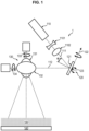
- the apparatus 1 may be an apparatus 1 for manufacturing an object, for example by additive manufacturing, for example by selective additive manufacturing.
- the object may be a three-dimensional object.
- the apparatus 1 may comprise a support 140.
- the support 140 may be adapted to support at least one layer 150 of material, for example of additive manufacturing material.
- the layer 150 of material may be a layer 150 of powder, for example of additive manufacturing powder.
- the apparatus 1 may comprise a source 110.
- the source 110 may be a consolidation source.
- the source 110 may be a radiation source, for example a laser source, for example a laser light source, for example adapted to emit a laser beam.
- the apparatus 1 may comprise a scanning device 130.
- the scanning device may be adapted to direct the laser beam, for example onto the layer 150, for example so as to scan at least a portion of the layer 150, for example along a scanning path.
- the apparatus 1 comprises a device 120, for example a modulation device 120, for example a scanning trajectory modulation device.
- the device 120 may be arranged upstream of the scanning device 130.
- the device 120 may comprise a mirror 121, for example a modulation mirror 121.
- the mirror 121 may be adapted to reflect the laser beam coming from the laser source and/or direct it towards the scanning device.
- the angle ⁇ of incidence of the laser beam coming from the laser source on the mirror 121 is between 20 and 45°, and/or the angle formed between the laser beam coming from the laser source and directed towards the device 120 and the laser beam coming from the device 120 and directed towards the scanning device 130 is between 40 and 90°.
- Angle of incidence refers to the angle between the direction of propagation of the laser beam and the normal to the mirror at the mirror surface encountered by the laser beam.
- Upstream and downstream means upstream and downstream relative to the direction of the photon flow of the laser beam emitted by the laser source, i.e. relative to the optical path of the laser beam. It is thus possible to modulate the main trajectory defined by the scanning device 130 by means of a prior modulation and to obtain a modulated trajectory.
- the modulation of the trajectory makes it possible to improve the distribution of energy provided by the laser source, which results in a widening of the fusion pool, hence a wider bead of fused material and a reduction of the number of vectors corresponding to the laser paths and consequently an increase in the melting rate, i.e. a larger melted surface for the same unit of time.
- a material needs a quantity of energy per unit of time, called fluence, expressed for example in J/mm 2 . If the fluence is too low, the melting is not complete and the material will not have the expected characteristics.
- the melt pool will be too dynamic, which will cause unwanted phenomena such as projections, sparks, significant fumes disturbing the laser beam, or bubbling. Such unwanted phenomena degrade the quality of the material obtained.
- the laser energy and the melting speed therefore the productivity, are limited in the prior art.
- the invention makes it possible to introduce, thanks to a modulation device which does not harm compactness and efficiency, modulations making it possible to superimpose a secondary trajectory on the powder bed on the main trajectory.
- the device thus increases the efficiency of energy transfer to matter. Indeed, since the power of a laser beam is highly localized, the material such as powder melts quickly and the resulting molten pool acts as a mirror for the photons. This results in a significant re-emission of the energy supplied in this setting.
- the modulation of the trajectory also allows better control of the cooling dynamics of the molten pool and therefore makes it possible to improve the state, in particular the metallurgical state in the case of a metal, of the material formed.
- Modulation also makes it possible, by choosing the modulation pattern, to adjust the quantity of energy deposited over the width of the molten pool, so as to adjust the energy, for example between the edges and the center of the molten pool or between one edge, the center and another edge, so as to limit unwanted phenomena such as projections and/or sparks.
- the device is particularly compact compared to a solution with multiple laser sources.
- the claimed arrangement requires only one laser and is particularly compact without compromising quality in terms of additive manufacturing.
- Such an apparatus can be obtained by modifying existing apparatuses without requiring extensive modification of the scanning device, for example without interfering with the actuator drive system of the scanning device.
- the laser source 110 comprises for example a fiber laser, for example a continuous laser for example a single-mode laser with a Gaussian energy distribution.
- the laser beam may have a power greater than or equal to 250 W, for example greater than or equal to 500 W, for example less than or equal to 5000 W, for example less than or equal to 3000 W, for example between 750 and 2500 W, for example equal to 1000 or 2000 W.
- the laser beam may come into contact with the layer 150 of powder, forming a laser spot or spot.
- the spot may have a given diameter, for example greater than or equal to 50 or 60 ⁇ m, for example less than or equal to 300 or 250 ⁇ m, for example between 50 and 250 ⁇ m, for example equal to 70 or 150 or 250 ⁇ m.
- the laser beam used for example, has a wavelength of 1070 nm.
- the apparatus 1 may comprise an optical element 1101 for controlling the focusing length, for example an optical lens for controlling the focusing length, for example arranged at the output of the laser source.
- the optical element for controlling the focusing length may be movable so as to adjust the focusing length, for example movable so as to approach and/or move it away from the laser source 110, for example movable along the axis formed by the laser beam 111 exiting the laser source.
- the apparatus 1 may comprise a focusing device 1102 between the optical element for controlling the focusing length, for example arranged between the laser source 110 and the modulation device 120.
- the apparatus 1 may comprise a device for shaping the laser beam, for example so as to homogenize the energy supplied to the surface, for example the upper surface, of the part of the scanned powder layer, for example so as to obtain a top hat or donut type energy distribution.
- the shaping device may be or comprise a diffractive lens or a refractive element.
- the scanning device 130 may comprise a first scanning mirror 131 and/or a second scanning mirror 132.
- the scanning device scanning device 130 can thus be adapted to modify the orientation of the first scanning mirror 131 and/or the second scanning mirror 132 along one or more rotation axes, for example over a range of scanning angle values.
- the scanning device 130 can be adapted to modify the orientation of the first scanning mirror 131 along a first scanning rotation axis 133, for example over a first range of scanning angle values.
- the scanning device 130 can be adapted to modify the orientation of the second scanning mirror 132 along a second scanning rotation axis 134, for example over a second range of scanning angle values.
- the scanning device 130 may be configured to change the orientation of the first scanning mirror 131 along the first scanning rotation axis 133 and/or of the second scanning mirror 132 along the second scanning rotation axis 134, at a scanning rotation speed.
- the first scanning mirror 131 may be adapted and/or controlled to reflect the laser beam 112 from the modulation mirror 121 and direct it toward the second scanning mirror 132.
- the second scanning mirror 132 may be adapted to reflect the laser beam from the first scanning mirror 131 and direct it onto the layer 150.
- the system may be adapted to control the orientation of the first scanning mirror 131 along the first scanning rotation axis 133 and of the second mirror 132 along the second scanning rotation axis 134 to control the scanning trajectory of the layer 150 by the laser beam along two degrees of freedom, for example in a plane of the powder layer, for example along two directions of the plane of the powder layer.
- the plane of the powder layer may be a plane corresponding to a surface, for example an upper surface, of the powder layer.
- the scanning device 130 may comprise at least one actuator, for example for modifying the orientation of the first scanning mirror 131 and/or the second scanning mirror 132.
- the scanning device 130 may thus comprise a first actuator for modifying the orientation of the first scanning mirror 131 along the first scanning rotation axis 133 and a second actuator for modifying the orientation of the second scanning mirror 132 along the second axis of rotation 134.
- the first scanning mirror 131 and/or the second scanning mirror 132 may be a plane mirror, and/or a shaped mirror, for example cut-out shaped, elliptical, or rectangular, for example square, or circular.
- the scanning device 130 may be adapted to impose on the laser beam, or direct the laser beam according to, a scanning trajectory or main trajectory at the level of at least a portion of the layer 150 of additive manufacturing powder.
- the scanning trajectory or main trajectory corresponds to the trajectory which would be followed by the laser beam in the absence of modulation by the modulation device 120. It therefore corresponds to a certain control of the scanning device 130.
- the final trajectory therefore depends on the main trajectory and the secondary trajectory as described below.
- the main trajectory may comprise one or more sections, for example rectilinear.
- the section(s) correspond(s) to portions of trajectory where the beam would actually reach the layer 150 of powder in the absence of modulation, thus forming the spot following the sections.
- the sections form, for example, vectors.
- the trajectory may comprise one or more jumps separating two sections, corresponding to portions where no laser beam would actually reach the layer 150 of powder in the absence of modulation because at the corresponding moment no laser beam is emitted or reaches the scanning device 130.
- At least two sections can be separated by a spacing, called vector spacing.
- the successive sections of the main trajectory are for example separated by the same spacing.
- the spacing is for example greater than 100 ⁇ m, for example greater than 200 ⁇ m, for example greater than 400 ⁇ m, for example less than 1000 ⁇ m, for example less than 700 ⁇ m, for example equal to 500 ⁇ m.
- the apparatus comprising the modulation device allows an increase in the vector spacing compared to the prior art and therefore greater efficiency by reducing the length of the main trajectory and therefore the manufacturing time.
- the scanning device 130 may comprise a three-axis scanning head.
- the apparatus 1 may then preferably comprise the optical element for controlling the focal length 1101 and/or the focusing device 1102 described above.
- the scanning device 130 may comprise a two-axis scanning head.
- the apparatus 1 may then preferably comprise a focusing device between the scanning device 130 and the layer 150.
- the focusing device comprises for example a lens, for example a flat-field lens, for example an F-Theta lens.
- the modulation device 120 may be adapted to modify the orientation of the modulation mirror 121, for example by rotation, for example along at least one rotation axis, over a range of modulation angle values.
- the modulation device 120 may be adapted to modify the orientation of the modulation mirror 121, for example along a first modulation rotation axis 122, for example over a first range of modulation values.
- the modulation device 120 may be adapted to modify the orientation of the modulation mirror 121 along a second modulation rotation axis 123, for example over a second range of modulation values.
- the first modulation rotation axis 122 and the second modulation rotation axis 123 may be two orthogonal axes.
- the first modulation value range and/or the second modulation value range has for example an amplitude between +/- 0.0025 rad and +/- 0.0015 rad, for example +/- 0.002 rad.
- the range of scanning angle values may be wider than the range of modulation angle values.
- the first and/or second range(s) of scanning angle values may be wider than the first and/or second range(s) of modulation angle values.
- the modulations are intended to modulate the scanning which determines the main trajectory, for example by imposing a secondary trajectory which is superimposed on the main trajectory resulting from the control of the scanning device 130.
- the modulation device 120 may comprise at least one actuator, for example to modify the orientation of the modulation mirror 121.
- the modulation device 120 may thus comprise a first actuator to modify the orientation of the modulation mirror along the first modulation rotation axis 122 and a second actuator to modify the orientation of the modulation mirror along the second modulation rotation axis 123.
- the at least one actuator may be or comprise a piezoelectric actuator, for example adapted to oscillate at least at an oscillation frequency greater than or equal to 1 kHz, for example greater than 1.5 kHz, for example greater than 2 kHz, for example less than 15 kHz, for example less than 12 kHz, for example between 1.5 and 10 kHz.
- a piezoelectric actuator for example adapted to oscillate at least at an oscillation frequency greater than or equal to 1 kHz, for example greater than 1.5 kHz, for example greater than 2 kHz, for example less than 15 kHz, for example less than 12 kHz, for example between 1.5 and 10 kHz.
- Such an actuator makes it possible to achieve high frequencies, while being compact and inexpensive.
- such an actuator allows high angular precision on the position during modulation, i.e. control of the amplitude, and on the return to a reference position corresponding to an absence of modulation.
- the at least one actuator for example the first actuator and/or the second actuator, may be or comprise an electromagnetic or mechanical actuator.
- the at least one actuator may be or comprise a microelectromechanical system, also called MEMS (microelectromechanical systems in English terminology), for example adapted to oscillate at least at an oscillation frequency greater than 10 kHz, for example greater than 15 kHz, for example equal to 20 kHz.
- MEMS microelectromechanical systems in English terminology
- the at least one actuator for example the first actuator and/or the second actuator, may be or comprise a galvanometer.
- the angle ⁇ of incidence of the laser beam coming from the laser source on the mirror 121 may be between 25 and 35°, and/or the angle formed between the laser beam coming from the laser source and directed towards the device 120 and the laser beam coming from the device 120 and directed towards the scanning device 130 may be between 50 and 70°.
- the laser beam may have a diameter between 20 and 40 mm when reflected from the modulation mirror, for example about 23 mm in diameter and/or a diameter between 50 and 100 ⁇ m at the surface of the powder layer.
- the modulation mirror For an angle of incidence ⁇ of 45°, for a laser beam of approximately 30 mm in diameter when reflected on the modulation mirror, the modulation mirror must have an elliptical reflection zone of at least 42 mm in length and 30 mm in width. On the other hand, for an angle of incidence of 30°, the modulation mirror can have an elliptical reflection zone of 35 mm in length and 30 mm in width. The associated mass is therefore reduced by around 18%.
- the angle of incidence of the laser beam from the laser source on the modulation mirror can be between 28 and 32°, for example equal to 30°.
- the modulation mirror 121 may be a mirror, for example a plane mirror, of shape, for example a cut-out shape, elliptical. Such a shape is particularly suitable for limiting the quantity of material, which allows rapid oscillation, without limiting the area that can be reached by the laser on the surface of the powder layer.
- the elliptical mirror has for example a length between D f /cos( ⁇ ) and 2 D f /cos( ⁇ ), where D f is the diameter of the laser beam and ⁇ the angle of incidence of the laser beam from the laser source on the modulation mirror, for example equal to 1.6 D f /cos( ⁇ ).
- the mirror has for example a width between D f and 1.1 D f , for example equal to Df.
- D f is for example the diameter of the laser beam at 1/e 2 , or D86 at 86% of the energy of a Gaussian spot.
- the modulation mirror 121 may be a rectangular mirror, for example square, or a circular mirror.
- the modulation mirror 121 may comprise a substrate and a reflection surface coating. Such a coating makes it possible to improve the reflection of photons on the mirror. Such a coating makes it possible to avoid or limit the absorption of the energy of the laser beam by the mirror, avoids or limits the heating of the mirror, the heating leading to deformation and reducing the quality of the beam. Such a coating thus makes it possible to increase the lifetime of the modulation mirror.
- the modulation mirror 121 comprises for example silicon carbide.
- the mirror comprises for example a substrate, the substrate being for example made of silicon carbide and/or is essentially made of silicon carbide.
- Silicon carbide offers good performance in terms of mass/rigidity, without having disadvantages specific to materials such as berylium, for example toxicity and difficulty of supply, as well as the cost of supply. It is thus possible to further reduce the mass and therefore the inertia of the modulation mirror, and therefore to further increase the oscillation frequency of the actuator(s) of the modulation device 120.
- the modulation device 120 can be adapted to modulate the trajectory according to a modulation.
- the modulation device 120 can thus be adapted to impose on the laser beam, or direct the laser beam according to, a modulation trajectory or secondary trajectory which is superimposed on the main trajectory at the level of at least a portion of the layer 150 of additive manufacturing powder.
- the modulation mirror 121 can be adapted to oscillate, for example along at least one axis, for example along two axes, for example along the first modulation rotation axis 122 and/or along the second modulation rotation axis 123.
- the modulation mirror 121 can thus be adapted to oscillate simultaneously and/or independently along the two axes, for example along the first modulation rotation axis 122 and/or along the second modulation rotation axis 123.
- the modulation mirror 121 can thus be adapted to oscillate according to first oscillations according to the first modulation rotation axis 122 and/or according to second oscillations according to the second modulation rotation axis 123.
- the modulation mirror 121 can be adapted to oscillate simultaneously according to first oscillations according to the first modulation rotation axis 122 and according to second oscillations according to the second modulation rotation axis 123, for example to generate a sinusoidal or circular pattern.
- the oscillations according to the first modulation rotation axis 122 and/or according to the second modulation rotation axis 123 can be controlled in amplitude and/or in frequency, for example independently between the two axes 122 and 123.
- the oscillations along the first modulation rotation axis 122 can be controlled so as to have a phase shift relative to the oscillations along the second rotation axis 123. Controlling the phase shift makes it possible, for example, to adjust the shape of the pattern, to change the shape of the pattern and/or to orient the pattern along the scanning direction.
- the oscillations allow for example resulting oscillations, for example specific to the secondary trajectory, at the level of the layer 150 of powder, of amplitude greater than 100 ⁇ m, for example greater than 200 ⁇ m, for example less than 2000 ⁇ m, for example less than 1000 ⁇ m, for example less than 750 ⁇ m, for example equal to 500 ⁇ m.
- the oscillations can allow to increase the width of the melt pool for the same speed of movement of the spot and the same fluence. It is thus possible to increase the vector spacing and therefore the surface productivity proportionally.
- the modulation mirror may be adapted to oscillate at a frequency greater than 1.5 kHz, preferably greater than 2.5 kHz, preferably greater than or equal to 10 kHz, for example along the first modulation rotation axis 122 and/or the second modulation rotation axis 123.
- the modulation may comprise a pattern, for example a periodic pattern, for example example repeated at a frequency greater than 1.5 kHz, preferably greater than 2.5 kHz, preferably greater than or equal to 10 kHz.
- the pattern is for example an oscillation.
- the modulation can form a pattern. It is thus possible, using the modulation device, to introduce modulations.
- the secondary trajectory may include a pattern, for example so as to superimpose a pattern on the primary trajectory at the surface of the powder layer portion.
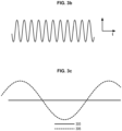
- the pattern is a sinusoid.
- the elements in bold represent the main trajectory comprising sections 301 separated by a gap 303 and jumps 302, while the elements in thin lines represent the modulated trajectory after superposition of the secondary trajectory so as to present sinusoidal oscillations and traveled by the laser spot 304.
- the corresponding secondary or modulation trajectory is represented as a variation along an axis as a function of time.
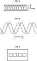
- the pattern is circular.
- the corresponding secondary or modulation trajectory is represented as a variation along an axis as a function of time.
- the modulation mirror 121 may be arranged at a converging portion of the laser beam coming from the laser source 110, for example downstream of the focusing device 1102 when the scanning device 130 comprises a three-axis scanning head. It is thus possible to limit the disturbance of the quality of the laser beam. Indeed, the laser beam at the output of the optical element for controlling the focusing length 1101 is divergent and only becomes convergent at the output of the focusing device 1102. Placing the modulation device 120 elsewhere, in particular further upstream, would risk disturbing the optical operation by decentering the laser beam.
- the apparatus 1 may further comprise one or more other laser sources 110, for example such as the laser source described above.
- One or more other laser sources 110 for example each other laser source 110, may be equipped with a scanning device 130, for example a scanning device 130 as described above, and/or a modulation device 120, for example a modulation device 120 as described above. It is thus possible to manufacture large-sized parts via a support and large powder layers, by implementing several laser sources and/or scanning devices and/or modulation devices in parallel to treat different areas of the powder layer or layers.
- the apparatus 1 may comprise control means adapted to control the apparatus, for example to control the laser source 110 and/or the modulation device 120 and/or the scanning device 130.
- the control means comprise or form, for example, a control unit.
- the control means comprise, for example, data storage means, for example a data storage unit, for example a random access memory and/or a read only memory.
- the storage means may be adapted to store instructions corresponding to the method described below.
- the control means include, for example, computing means, for example a processor.
- the control means may be configured to implement a method as described below.
- the method can be implemented by means of the apparatus 1.
- the method may comprise a step 400 of controlling the scanning device 130 according to a command to scan at least a portion of the layer 150 of additive manufacturing powder according to the scanning trajectory or main trajectory.
- the method may comprise a step 402, implemented at the same time as the control of the scanning device of step 400, of controlling the device modulation 120 according to a scanning path modulation command.
- the scanning path modulation command corresponds for example to the secondary path or modulation path.
- Steps 400 and 402 may be implemented such that the laser beam follows a modulated scanning path at the powder layer 150.
- the modulated scanning path may correspond to the superposition of the modulation path on the scanning path.
- step 400 of controlling the scanning device 130 the scanning device can be controlled so as to modify the orientation of the first scanning mirror 131 and/or the second scanning mirror 132 along the second scanning rotation axis 134 at a scanning rotation speed.
- step 402 of controlling the modulation device 120 the modulation device 120 can be controlled so as to modify the orientation of the modulation mirror 121 along the first rotation axis and/or second rotation axis(es), respectively 122 and/or 123, of modulation at the modulation rotation speed.
- the scanning rotation speed can be lower than the modulation rotation speed.
- an exemplary apparatus according to the prior art without the modulation device 120 would require a spacing of 50 ⁇ m and would be limited to a laser power of 200 W, so that it would achieve a surface melting rate of 600 cm 2 /min, whereas an exemplary apparatus such as the apparatus described, which includes the modulation device 120, can for example allow a spacing of 500 ⁇ m and a secondary trajectory oscillation width of 500 ⁇ m, and exploit a higher laser power, for example from 1000 to 2000 W, allowing a surface melting rate of 3000 to 6000 cm 2 /min and a productivity surface area thus improved by a ratio of 5 to 10.
Landscapes
- Engineering & Computer Science (AREA)
- Chemical & Material Sciences (AREA)
- Materials Engineering (AREA)
- Physics & Mathematics (AREA)
- Manufacturing & Machinery (AREA)
- Optics & Photonics (AREA)
- Mechanical Engineering (AREA)
- Health & Medical Sciences (AREA)
- Toxicology (AREA)
- Plasma & Fusion (AREA)
- General Health & Medical Sciences (AREA)
- Automation & Control Theory (AREA)
- General Physics & Mathematics (AREA)
- Ceramic Engineering (AREA)
- Analytical Chemistry (AREA)
- Laser Beam Processing (AREA)
- Powder Metallurgy (AREA)
- Mechanical Optical Scanning Systems (AREA)
- Exposure And Positioning Against Photoresist Photosensitive Materials (AREA)
Claims (11)
- Vorrichtung zum Fertigen eines dreidimensionalen Objekts durch selektive additive Fertigung, umfassend:- einen Träger (140), der zum Tragen mindestens einer Schicht (150) aus Pulver für die additive Fertigung angepasst ist,- eine Laserquelle (110), die zum Emittieren eines Laserstrahls (111) angepasst ist,- eine Abtastvorrichtung (130), die zum Richten des Laserstrahls auf die Pulverschicht angepasst ist, um mindestens einen Teil der Pulverschicht abzutasten,- eine Abtastbahnmodulationsvorrichtung (120), die stromaufwärts der Abtastvorrichtung angeordnet ist, die Modulationsvorrichtung umfassend einen Modulationsspiegel (121), der zum Reflektieren des Laserstrahls, der von der Laserquelle kommt, und Richten davon zu der Abtastvorrichtung angepasst ist,dadurch gekennzeichnet, dass
der Einfallswinkel des Laserstrahls, der von der Laserquelle kommt, auf den Modulationsspiegel zwischen 20 und 45° beträgt, und dass die Modulationsvorrichtung (120) zum Modifizieren der Ausrichtung des Modulationsspiegels entlang einer ersten Modulationsdrehachse (122) und entlang einer zweiten Modulationsdrehachse (123) angepasst ist. - Vorrichtung nach Anspruch 1, wobei die Abtastvorrichtung (130) einen ersten Abtastspiegel (131) und/oder einen zweiten Abtastspiegel (132) umfasst, wobei die Abtastvorrichtung zum Modifizieren der Ausrichtung des ersten Abtastspiegels entlang einer ersten Abtastdrehachse (133) und/oder des zweiten Abtastspiegels entlang einer zweiten Abtastdrehachse (134) angepasst ist.
- Vorrichtung nach Anspruch 2, wobei die Abtastvorrichtung zum Modifizieren der Ausrichtung des ersten Abtastspiegels (131) entsprechend der ersten Abtastdrehachse (133) über einen ersten Bereich von Abtastwinkelwerten und/oder des zweiten Abtastspiegels (132) entsprechend der zweiten Abtastdrehachse (134) über einen zweiten Bereich von Abtastwinkelwerten angepasst ist,wobei die Modulationsvorrichtung (120) zum Modifizieren der Ausrichtung des Modulationsspiegels entsprechend der ersten Modulationsdrehachse (122) über einen ersten Bereich von Modulationswinkelwerten und der zweiten Modulationsdrehachse (123) über einen zweiten Bereich von Modulationswinkelwerten angepasst ist,wobei der erste und/oder zweite Bereich von Abtastwinkelwerten breiter als der erste und/oder zweite Bereich von Modulationswinkelwerten ist.
- Vorrichtung nach Anspruch 2 oder 3, wobei die Abtastvorrichtung (130) zum Modifizieren der Ausrichtung des ersten Abtastspiegels (131) entlang der ersten Abtastdrehachse (133) und/oder des zweiten Abtastspiegels (132) entlang der zweiten Abtastdrehachse (134) mit einer Abtastdrehgeschwindigkeit angepasst ist,wobei die Modulationsvorrichtung (120) zum Modifizieren der Ausrichtung des Modulationsspiegels (121) entsprechend der ersten Modulationsdrehachse (122) und der zweiten Modulationsdrehachse (123) mit einer Modulationsdrehgeschwindigkeit angepasst ist,wobei die Abtastdrehgeschwindigkeit niedriger als die Modulationsdrehgeschwindigkeit ist.
- Vorrichtung nach einem der Ansprüche 2 bis 4, wobei die Abtastvorrichtung den ersten Abtastspiegel (131) und den zweiten Abtastspiegel (132) umfasst, wobei der erste Abtastspiegel zum Reflektieren des Laserstrahls, der von dem Modulationsspiegel (121) kommt, und Richten davon zu dem zweiten Abtastspiegel angepasst ist, wobei der zweite Abtastspiegel zum Reflektieren des Laserstrahls, der von dem ersten Abtastspiegel kommt, und Richten davon auf die Schicht (150) aus Pulver für die additive Fertigung angepasst ist, wobei das System zum Steuern der Ausrichtung des ersten Abtastspiegels entlang der ersten Abtastdrehachse und des zweiten Spiegels entlang der zweiten Abtastdrehachse zum Steuern der Abtastbahn der Pulverschicht durch den Laserstrahl entsprechend zwei Freiheitsgraden in einer Ebene der Pulverschicht angepasst ist.
- Vorrichtung nach einem der Ansprüche 1 bis 5, wobei die Modulationsvorrichtung (120) zum Modulieren der Bahn entsprechend einer Modulation angepasst ist, umfassend eine Schwingung mit einer Frequenz größer als 1,5 kHz, vorzugsweise größer als oder gleich 10 kHz.
- Vorrichtung nach einem der Ansprüche 1 bis 6, wobei der Einfallswinkel des Laserstrahls, der von der Laserquelle kommt, auf den Modulationsspiegel zwischen 25 und 35° beträgt.
- Vorrichtung nach einem der Ansprüche 1 bis 7, wobei der Modulationsspiegel (121) Siliziumkarbid umfasst.
- Vorrichtung nach einem der Ansprüche 1 bis 8, wobei der Modulationsspiegel (121) ein ellipsenförmiger Spiegel ist.
- Verfahren zum Fertigen eines dreidimensionalen Objekts durch selektive additive Fertigung, das mittels der Vorrichtung nach einem der vorstehenden Ansprüche implementiert wird, umfassend die folgenden Schritte:- Steuern der Abtastvorrichtung (130) entsprechend einem Abtastbefehl von mindestens einem Teil der Schicht (150) aus Pulver für die additive Fertigung entsprechend einer Abtastbahn, und- gleichzeitig mit dem Steuern der Abtastvorrichtung, Steuern der Modulationsvorrichtung (120) entsprechend einem Modulationsbefehl der Abtastbahn,
sodass der Laserstrahl auf der Pulverschicht (150) einer modulierten Abtastbahn folgt. - Verfahren nach Anspruch 10, wobei:- bei dem Schritt des Steuerns der Modulationsvorrichtung (120) die Modulationsvorrichtung so gesteuert wird, dass die Ausrichtung des Modulationsspiegels (121) entsprechend der ersten und/oder der zweiten Modulationsdrehachse (122, 123) mit einer Modulationsdrehgeschwindigkeit modifiziert wird,- bei dem Schritt des Steuerns der Abtastvorrichtung (130) die Abtastvorrichtung so gesteuert wird, dass die Ausrichtung des ersten Abtastspiegels (131) entlang der ersten Abtastdrehachse (133) und/oder des zweiten Abtastspiegels (132) entlang der zweiten Abtastdrehachse (134) mit einer Abtastdrehgeschwindigkeit modifiziert wird, die niedriger als die Modulationsdrehgeschwindigkeit ist.
Applications Claiming Priority (2)
| Application Number | Priority Date | Filing Date | Title |
|---|---|---|---|
| FR1853547A FR3080321B1 (fr) | 2018-04-23 | 2018-04-23 | Appareil et procede pour fabriquer un objet tridimensionnel |
| PCT/FR2019/050942 WO2019207239A1 (fr) | 2018-04-23 | 2019-04-19 | Appareil et procédé pour fabriquer un objet tridimensionnel |
Publications (3)
| Publication Number | Publication Date |
|---|---|
| EP3784492A1 EP3784492A1 (de) | 2021-03-03 |
| EP3784492C0 EP3784492C0 (de) | 2025-05-28 |
| EP3784492B1 true EP3784492B1 (de) | 2025-05-28 |
Family
ID=62874954
Family Applications (1)
| Application Number | Title | Priority Date | Filing Date |
|---|---|---|---|
| EP19728475.5A Active EP3784492B1 (de) | 2018-04-23 | 2019-04-19 | Vorrichtung und verfahren zur herstellung eines dreidimensionalen objekts |
Country Status (7)
| Country | Link |
|---|---|
| US (1) | US12030244B2 (de) |
| EP (1) | EP3784492B1 (de) |
| JP (1) | JP7379375B2 (de) |
| KR (1) | KR20210003823A (de) |
| CN (1) | CN112313079B (de) |
| FR (1) | FR3080321B1 (de) |
| WO (1) | WO2019207239A1 (de) |
Families Citing this family (9)
| Publication number | Priority date | Publication date | Assignee | Title |
|---|---|---|---|---|
| US12115596B2 (en) * | 2020-01-27 | 2024-10-15 | National Technology & Engineering Solutions Of Sandia, Llc | Methods for site-specific enhancement of soft magnetic alloys |
| EP4106938A4 (de) * | 2020-02-18 | 2024-04-24 | Vulcanforms Inc. | Systeme zur additiven herstellung und zugehörige verfahren unter verwendung einer optischen phasengesteuerten gruppenstrahllenkung |
| FR3110096B1 (fr) * | 2020-05-12 | 2023-03-17 | Addup | Procédé de fabrication additive d’un objet à partir d’une couche de poudre |
| FR3110094B1 (fr) * | 2020-05-12 | 2023-07-28 | Addup | Procédé de fabrication additive d’un objet à partir d’une couche de poudre |
| WO2022018148A1 (de) * | 2020-07-21 | 2022-01-27 | Trumpf Laser- Und Systemtechnik Gmbh | Fertigungseinrichtung und verfahren zum additiven herstellen eines bauteils aus einem pulvermaterial, sowie verfahren zum erzeugen eines bestimmten intensitätsprofils eines energiestrahls |
| WO2022018149A1 (de) * | 2020-07-21 | 2022-01-27 | Trumpf Laser- Und Systemtechnik Gmbh | Fertigungseinrichtung zum additiven fertigen von bauteilen aus einem pulvermaterial, verfahren zum verändern eines strahlprofils eines energiestrahls, und verwendung von wenigstens einem akustooptischen deflektor |
| CN116174747B (zh) * | 2022-12-06 | 2023-07-25 | 杭州爱新凯科技有限公司 | 一种多通道激光3d打印装置及其扫描方法 |
| GB202218751D0 (en) | 2022-12-13 | 2023-01-25 | Renishaw Plc | Powder bed fusion apparatus and methods |
| AT527863B1 (de) * | 2023-12-18 | 2025-09-15 | Trotec Laser Gmbh | Laserbearbeitungsmaschine, insbesondere Laserplotter oder Flachbett-Laserplotter, und Verfahren |
Family Cites Families (16)
| Publication number | Priority date | Publication date | Assignee | Title |
|---|---|---|---|---|
| US5352405A (en) * | 1992-12-18 | 1994-10-04 | Dtm Corporation | Thermal control of selective laser sintering via control of the laser scan |
| US5393482A (en) | 1993-10-20 | 1995-02-28 | United Technologies Corporation | Method for performing multiple beam laser sintering employing focussed and defocussed laser beams |
| US5427733A (en) * | 1993-10-20 | 1995-06-27 | United Technologies Corporation | Method for performing temperature-controlled laser sintering |
| WO2005060009A1 (en) * | 2003-12-18 | 2005-06-30 | The University Of Sydney | A beam splitter |
| KR100514996B1 (ko) * | 2004-04-19 | 2005-09-15 | 주식회사 이오테크닉스 | 레이저 가공 장치 |
| JP2010537230A (ja) * | 2007-08-16 | 2010-12-02 | ダウ コーニング コーポレーション | 炭化ケイ素系の層を用いて形成した二色性フィルター |
| US8081364B2 (en) | 2007-11-27 | 2011-12-20 | Duke University | High-speed multi-dimensional beam scanning system with angle amplification |
| FR3027841B1 (fr) | 2014-11-04 | 2017-05-19 | Michelin & Cie | Machine et procede pour la fabrication additive a base de poudre |
| CN107530972A (zh) * | 2015-03-18 | 2018-01-02 | 埃托雷·毛里齐奥·科斯塔贝伯 | 具有改进的光学单元的立体光固化成型机 |
| GB201505458D0 (en) | 2015-03-30 | 2015-05-13 | Renishaw Plc | Additive manufacturing apparatus and methods |
| JP6395681B2 (ja) | 2015-08-28 | 2018-09-26 | 三菱電機株式会社 | レーザ加工装置 |
| GB201516681D0 (en) * | 2015-09-21 | 2015-11-04 | Renishaw Plc | Addictive manufacturing apparatus and an optical module for use in an addictive manufacturing apparatus |
| DE102016107058A1 (de) * | 2015-12-17 | 2017-07-06 | Lilas Gmbh | 3D-Druck-Vorrichtung für die Herstellung eines räumlich ausgedehnten Produkts |
| JP2017148829A (ja) | 2016-02-24 | 2017-08-31 | サイバーレーザー株式会社 | 超短パルスレーザー加工装置 |
| CN106092979A (zh) * | 2016-05-30 | 2016-11-09 | 杭州电子科技大学 | 利用阵列探测器实现荧光能量比率的牙菌斑定量检测装置 |
| WO2018106586A1 (en) * | 2016-12-06 | 2018-06-14 | Velo3D, Inc. | Optics, detectors, and three-dimensional printing |
-
2018
- 2018-04-23 FR FR1853547A patent/FR3080321B1/fr active Active
-
2019
- 2019-04-19 WO PCT/FR2019/050942 patent/WO2019207239A1/fr not_active Ceased
- 2019-04-19 US US17/050,250 patent/US12030244B2/en active Active
- 2019-04-19 KR KR1020207033161A patent/KR20210003823A/ko not_active Ceased
- 2019-04-19 CN CN201980040671.1A patent/CN112313079B/zh not_active Expired - Fee Related
- 2019-04-19 EP EP19728475.5A patent/EP3784492B1/de active Active
- 2019-04-19 JP JP2020559406A patent/JP7379375B2/ja active Active
Also Published As
| Publication number | Publication date |
|---|---|
| CN112313079A (zh) | 2021-02-02 |
| KR20210003823A (ko) | 2021-01-12 |
| WO2019207239A1 (fr) | 2019-10-31 |
| CN112313079B (zh) | 2023-03-24 |
| EP3784492C0 (de) | 2025-05-28 |
| JP7379375B2 (ja) | 2023-11-14 |
| US20210178481A1 (en) | 2021-06-17 |
| JP2021522072A (ja) | 2021-08-30 |
| FR3080321A1 (fr) | 2019-10-25 |
| US12030244B2 (en) | 2024-07-09 |
| EP3784492A1 (de) | 2021-03-03 |
| FR3080321B1 (fr) | 2020-03-27 |
Similar Documents
| Publication | Publication Date | Title |
|---|---|---|
| EP3784492B1 (de) | Vorrichtung und verfahren zur herstellung eines dreidimensionalen objekts | |
| CH640448A5 (fr) | Procede d'ebavurage d'une piece mecanique et dispositif de mise en oeuvre du procede. | |
| EP3060957B1 (de) | Modulares lasergerät | |
| EP4149743B1 (de) | Verfahren und vorrichtung zur additiven herstellung eines bauteils aus einer pulverschicht | |
| KR102618163B1 (ko) | 레이저 가공 장치 | |
| TWI454331B (zh) | 可變景深之光學系統與調制方法及其光學加工方法 | |
| EP0995145B1 (de) | Beugungsoptik mit zusammengesetzter apertur und veränderlicher brennweite und laserschneidevorrichtung mit dieser optik | |
| EP4149744B1 (de) | Verfahren und vorrichtung zur additiven herstellung eines bauteils aus einer pulverschicht | |
| EP0038297B1 (de) | Verfahren zum Entgräten eines scharfen Instruments, Ausführung des Verfahrens und durch dieses Verfahren erhaltenes scharfes Instrument | |
| EP3645207B1 (de) | Verfahren zur strukturierung eines substrats, anordnung mit einem substrat und vorrichtung zur strukturierung des substrats | |
| BE1027700B1 (fr) | Dispositif pour un système optique d’usinage laser | |
| EP3956095B1 (de) | Verfahren zur erzeugung eines irisierenden effekts auf der oberfläche eines materials und vorrichtungen zur durchführung des besagten verfahrens | |
| EP4051444B1 (de) | Vorrichtung und verfahren zur abscheidung von teilchen mittels laserschockwellen | |
| US20190316247A1 (en) | Laser ablation arrangement and method | |
| WO2024002600A1 (fr) | Dispositif optique de balayage d'un faisceau lumineux sur une pièce à usiner | |
| WO2020212729A1 (fr) | Procédé de réalisation d'un effet visuel d'irisation sur la surface d'un matériau, dispositifs pour sa mise en oeuvre et pièce ainsi obtenue | |
| EP1249301A1 (de) | Vorrichtung und damit assoziertes so genanntes zweilagiges Laserschweissverfahren | |
| JP6990958B2 (ja) | レーザー加工装置 | |
| FR3142882A1 (fr) | Systeme de decoupe d’un tissu oculaire en portions elementaires | |
| EP2847633A1 (de) | Optisches system | |
| WO2013167622A1 (fr) | Systeme optique pour dispositif de déflexion | |
| WO2012069707A1 (fr) | Système réfléchissant |
Legal Events
| Date | Code | Title | Description |
|---|---|---|---|
| STAA | Information on the status of an ep patent application or granted ep patent |
Free format text: STATUS: UNKNOWN |
|
| STAA | Information on the status of an ep patent application or granted ep patent |
Free format text: STATUS: THE INTERNATIONAL PUBLICATION HAS BEEN MADE |
|
| PUAI | Public reference made under article 153(3) epc to a published international application that has entered the european phase |
Free format text: ORIGINAL CODE: 0009012 |
|
| STAA | Information on the status of an ep patent application or granted ep patent |
Free format text: STATUS: REQUEST FOR EXAMINATION WAS MADE |
|
| 17P | Request for examination filed |
Effective date: 20201123 |
|
| AK | Designated contracting states |
Kind code of ref document: A1 Designated state(s): AL AT BE BG CH CY CZ DE DK EE ES FI FR GB GR HR HU IE IS IT LI LT LU LV MC MK MT NL NO PL PT RO RS SE SI SK SM TR |
|
| AX | Request for extension of the european patent |
Extension state: BA ME |
|
| DAV | Request for validation of the european patent (deleted) | ||
| DAX | Request for extension of the european patent (deleted) | ||
| RAP3 | Party data changed (applicant data changed or rights of an application transferred) |
Owner name: ADDUP |
|
| STAA | Information on the status of an ep patent application or granted ep patent |
Free format text: STATUS: EXAMINATION IS IN PROGRESS |
|
| 17Q | First examination report despatched |
Effective date: 20230118 |
|
| REG | Reference to a national code |
Ref country code: DE Free format text: PREVIOUS MAIN CLASS: B33Y0010000000 Ipc: B29C0064268000 Ref country code: DE Ref legal event code: R079 Ref document number: 602019070515 Country of ref document: DE Free format text: PREVIOUS MAIN CLASS: B33Y0010000000 Ipc: B29C0064268000 |
|
| GRAP | Despatch of communication of intention to grant a patent |
Free format text: ORIGINAL CODE: EPIDOSNIGR1 |
|
| STAA | Information on the status of an ep patent application or granted ep patent |
Free format text: STATUS: GRANT OF PATENT IS INTENDED |
|
| RIC1 | Information provided on ipc code assigned before grant |
Ipc: B22F 10/36 20210101ALI20241223BHEP Ipc: B22F 12/49 20210101ALI20241223BHEP Ipc: B22F 12/44 20210101ALI20241223BHEP Ipc: B22F 10/28 20210101ALI20241223BHEP Ipc: G02B 26/10 20060101ALI20241223BHEP Ipc: B23K 26/354 20140101ALI20241223BHEP Ipc: B29C 64/153 20170101ALI20241223BHEP Ipc: B33Y 30/00 20150101ALI20241223BHEP Ipc: B22F 3/105 20060101ALI20241223BHEP Ipc: B33Y 10/00 20150101ALI20241223BHEP Ipc: B29C 64/268 20170101AFI20241223BHEP |
|
| INTG | Intention to grant announced |
Effective date: 20250124 |
|
| GRAS | Grant fee paid |
Free format text: ORIGINAL CODE: EPIDOSNIGR3 |
|
| GRAA | (expected) grant |
Free format text: ORIGINAL CODE: 0009210 |
|
| STAA | Information on the status of an ep patent application or granted ep patent |
Free format text: STATUS: THE PATENT HAS BEEN GRANTED |
|
| AK | Designated contracting states |
Kind code of ref document: B1 Designated state(s): AL AT BE BG CH CY CZ DE DK EE ES FI FR GB GR HR HU IE IS IT LI LT LU LV MC MK MT NL NO PL PT RO RS SE SI SK SM TR |
|
| REG | Reference to a national code |
Ref country code: GB Ref legal event code: FG4D Free format text: NOT ENGLISH |
|
| REG | Reference to a national code |
Ref country code: CH Ref legal event code: EP |
|
| REG | Reference to a national code |
Ref country code: IE Ref legal event code: FG4D Free format text: LANGUAGE OF EP DOCUMENT: FRENCH Ref country code: DE Ref legal event code: R096 Ref document number: 602019070515 Country of ref document: DE |
|
| U01 | Request for unitary effect filed |
Effective date: 20250528 |
|
| U07 | Unitary effect registered |
Designated state(s): AT BE BG DE DK EE FI FR IT LT LU LV MT NL PT RO SE SI Effective date: 20250606 |
|
| PG25 | Lapsed in a contracting state [announced via postgrant information from national office to epo] |
Ref country code: ES Free format text: LAPSE BECAUSE OF FAILURE TO SUBMIT A TRANSLATION OF THE DESCRIPTION OR TO PAY THE FEE WITHIN THE PRESCRIBED TIME-LIMIT Effective date: 20250528 |
|
| PG25 | Lapsed in a contracting state [announced via postgrant information from national office to epo] |
Ref country code: GR Free format text: LAPSE BECAUSE OF FAILURE TO SUBMIT A TRANSLATION OF THE DESCRIPTION OR TO PAY THE FEE WITHIN THE PRESCRIBED TIME-LIMIT Effective date: 20250829 Ref country code: NO Free format text: LAPSE BECAUSE OF FAILURE TO SUBMIT A TRANSLATION OF THE DESCRIPTION OR TO PAY THE FEE WITHIN THE PRESCRIBED TIME-LIMIT Effective date: 20250828 |
|
| PG25 | Lapsed in a contracting state [announced via postgrant information from national office to epo] |
Ref country code: PL Free format text: LAPSE BECAUSE OF FAILURE TO SUBMIT A TRANSLATION OF THE DESCRIPTION OR TO PAY THE FEE WITHIN THE PRESCRIBED TIME-LIMIT Effective date: 20250528 |
|
| PG25 | Lapsed in a contracting state [announced via postgrant information from national office to epo] |
Ref country code: HR Free format text: LAPSE BECAUSE OF FAILURE TO SUBMIT A TRANSLATION OF THE DESCRIPTION OR TO PAY THE FEE WITHIN THE PRESCRIBED TIME-LIMIT Effective date: 20250528 |
|
| PG25 | Lapsed in a contracting state [announced via postgrant information from national office to epo] |
Ref country code: RS Free format text: LAPSE BECAUSE OF FAILURE TO SUBMIT A TRANSLATION OF THE DESCRIPTION OR TO PAY THE FEE WITHIN THE PRESCRIBED TIME-LIMIT Effective date: 20250828 |
|
| PG25 | Lapsed in a contracting state [announced via postgrant information from national office to epo] |
Ref country code: IS Free format text: LAPSE BECAUSE OF FAILURE TO SUBMIT A TRANSLATION OF THE DESCRIPTION OR TO PAY THE FEE WITHIN THE PRESCRIBED TIME-LIMIT Effective date: 20250928 |