EP3784151B1 - Einwegraspel für medizinische instrumente - Google Patents
Einwegraspel für medizinische instrumente Download PDFInfo
- Publication number
- EP3784151B1 EP3784151B1 EP18916571.5A EP18916571A EP3784151B1 EP 3784151 B1 EP3784151 B1 EP 3784151B1 EP 18916571 A EP18916571 A EP 18916571A EP 3784151 B1 EP3784151 B1 EP 3784151B1
- Authority
- EP
- European Patent Office
- Prior art keywords
- rasp head
- rasp
- tool
- height
- head
- Prior art date
- Legal status (The legal status is an assumption and is not a legal conclusion. Google has not performed a legal analysis and makes no representation as to the accuracy of the status listed.)
- Active
Links
Images


Classifications
-
- A—HUMAN NECESSITIES
- A61—MEDICAL OR VETERINARY SCIENCE; HYGIENE
- A61B—DIAGNOSIS; SURGERY; IDENTIFICATION
- A61B17/00—Surgical instruments, devices or methods
- A61B17/16—Instruments for performing osteoclasis; Drills or chisels for bones; Trepans
- A61B17/1659—Surgical rasps, files, planes, or scrapers
-
- A—HUMAN NECESSITIES
- A61—MEDICAL OR VETERINARY SCIENCE; HYGIENE
- A61B—DIAGNOSIS; SURGERY; IDENTIFICATION
- A61B17/00—Surgical instruments, devices or methods
- A61B17/16—Instruments for performing osteoclasis; Drills or chisels for bones; Trepans
- A61B17/1613—Component parts
- A61B17/1615—Drill bits, i.e. rotating tools extending from a handpiece to contact the worked material
- A61B17/1617—Drill bits, i.e. rotating tools extending from a handpiece to contact the worked material with mobile or detachable parts
-
- A—HUMAN NECESSITIES
- A61—MEDICAL OR VETERINARY SCIENCE; HYGIENE
- A61B—DIAGNOSIS; SURGERY; IDENTIFICATION
- A61B17/00—Surgical instruments, devices or methods
- A61B17/16—Instruments for performing osteoclasis; Drills or chisels for bones; Trepans
- A61B17/1662—Instruments for performing osteoclasis; Drills or chisels for bones; Trepans for particular parts of the body
- A61B17/1671—Instruments for performing osteoclasis; Drills or chisels for bones; Trepans for particular parts of the body for the spine
-
- A—HUMAN NECESSITIES
- A61—MEDICAL OR VETERINARY SCIENCE; HYGIENE
- A61B—DIAGNOSIS; SURGERY; IDENTIFICATION
- A61B17/00—Surgical instruments, devices or methods
- A61B17/32—Surgical cutting instruments
- A61B17/3209—Incision instruments
- A61B17/3211—Surgical scalpels, knives; Accessories therefor
-
- A—HUMAN NECESSITIES
- A61—MEDICAL OR VETERINARY SCIENCE; HYGIENE
- A61B—DIAGNOSIS; SURGERY; IDENTIFICATION
- A61B17/00—Surgical instruments, devices or methods
- A61B2017/0023—Surgical instruments, devices or methods disposable
-
- A—HUMAN NECESSITIES
- A61—MEDICAL OR VETERINARY SCIENCE; HYGIENE
- A61B—DIAGNOSIS; SURGERY; IDENTIFICATION
- A61B17/00—Surgical instruments, devices or methods
- A61B2017/0042—Surgical instruments, devices or methods with special provisions for gripping
- A61B2017/00429—Surgical instruments, devices or methods with special provisions for gripping with a roughened portion
-
- A—HUMAN NECESSITIES
- A61—MEDICAL OR VETERINARY SCIENCE; HYGIENE
- A61B—DIAGNOSIS; SURGERY; IDENTIFICATION
- A61B17/00—Surgical instruments, devices or methods
- A61B2017/00526—Methods of manufacturing
-
- A—HUMAN NECESSITIES
- A61—MEDICAL OR VETERINARY SCIENCE; HYGIENE
- A61B—DIAGNOSIS; SURGERY; IDENTIFICATION
- A61B17/00—Surgical instruments, devices or methods
- A61B17/32—Surgical cutting instruments
- A61B2017/320004—Surgical cutting instruments abrasive
- A61B2017/320008—Scrapers
Definitions
- the invention relates to the technical field of a disposable cutting tool.
- This disclosure relates to a plastic disposable mount to withstand forces applied to a shaft supporting a cutting tool.
- Orthopedic surgical procedures can require the creation or enlargement of holes in bones, affixation or removal of fasteners and the like.
- Reusable devices require constant recalibration and sterilization to avoid contamination.
- US 2016/262773 A1 relates to an orthopaedic surgical rasp comprising a metallic cutting insert and a handle molded thereto.
- US 2010/262146 A1 relates to disposable bone cutting instrument, in particular a helical reamer for reaming a bone cavity has a longitudinally extending support shaft having a first driven end and a second end having a tip for insertion into the bone cavity.
- US 3 748 736 relates to a surgical knife having a blade and a handle integrally molded on the blade.
- the tool has a molded neck region extending from the body and formed within the fluid connection.
- a molded collar region is connected to the neck region and formed within a fluid passageway in the rasp head.
- the passageway extends into sides fluidly connected to the passageway.
- the passageway may be one or more of orthogonal and perpendicular to the shaft extending from the top side to the bottom side of the rasp head; at an acute angle to the shaft; at an oblique angle to the shaft; and "Y" shaped extending from the top side to the bottom side of the rasp head.
- At least one of the rasp head and the support shaft are tapered. In some instances wherein at least one of the top side and bottom side of the rasp head is parallel to the axis of the rasp head and the other side is angled relative to the axis of the rasp head, in other instances at least on side is convex or concave relative to the other side.
- the non-circular regions are at least one of divots, bumps and non-homogeneous generally flat regions.
- aspects of implementations of devices and of attaching a rasp head including forming a metal rasp head having a fluid pathway there through then molding an elongated body with support shaft co-molded into the rasp head via said fluid pathway with the fluid pathway branching into one or more sides.
- the branches are formed at one of an actuate and oblique angle to the shaft.
- Rasp tools are an essential part of many surgical procedures. When implanting support devices or replacing bone, a rasp is a commonly used instrument to prepare surfaces for connection. Rasp may also be used to file down bone or alter connecting tissue. Important to any surgery is to minimize contamination, infection and costs.
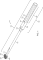
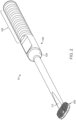
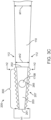
- Figures 1 and 2 show exterior perspective views of a hybrid rasp tool 10.
- the body 100 is a plastic injection molded elongated member with a distal end and a proximal end.
- the handle portion 102 is at one end and the rasp head 200 is at the opposite end.
- the handle portion may be configured to have varying surface region 103 with features such as bumps 104 or divots 105.
- the bumps and divots may form ring like geometries round all or a portion of the varying surface region 103.
- the varying surface region may be adjacent to a tubular region 106.
- the tubular region may have one or more non-homogeneous gripping areas 107 such as a flat area configured to press a thumb or finger against during griping.
- the handle portion may taper via a neck 109 to a smaller diameter support shaft 110.
- the shaft may be generally circular.
- the portion of the shaft adjacent to the rasp head 200 may be asymmetrically tapered via a tapered region 112 to narrow the shaft to the height of the rasp head 200.
- the tapered region may be positioned along one or both of the top and bottom faces of the rasp head
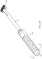
- Figure 3A shows a rear perspective view of the rasp tool.
- Figures 3B and 3C show side views of the rasp tool of Figure 3A .
- the distal end 150 of the body is visible.
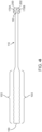
- Figure 4 shows a cut-away view of the hybrid rasp of figure 3 along the line of "A-A".
- the body is non-metallic, should be moldable via injection molding, and may be formed of plastics, composites, resins, glass filled plastic or resins and the like.
- the rasp body may also have non-homogeneous gripping areas 107 opposite each other.
- Important when using a rasp device is that the user have a firm grip. During a surgical procedure a surgeon will often have fluids and material on gloves and such fluids will acts as a lubricant thereby promoting slippage of the hand from a grip. By contouring the body with non-homogeneous gripping areas 107 and bumps and divots the user's grip may be improved and slippage reduced.
- a disposable rasp tool allows fort the disposal of all medical waste associated with the tool during disposal of the tool. Unlike metal rasp tools a hybrid rasp tool may be configured to provide flex to assist the user in positioning and using the tool.
- the rasp head 200 may be configured with concave, convex, flat or tapered top sides and /or bottom sides.
- the rasp head or heads (in a kit of rasps) may also be formed to mimic the normal lordosis shape of a spine at a predetermined vertebral level.
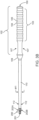
- the rasp head or heads (in a kit of rasps) may also be formed to mimic non normal shapes of a spine and thereby selected to match a shape presented by a specific spine. Shown in figure 3C is a tapered rasp head with a first height "h1" at the proximal end of the rasp 201 and measured between the top side of the rasp 205 and the bottom side of the rasp 207.
- the rasp head has a second height "h2" at the distal end of the rasp 202 and measured between the top side of the rasp 205 and the bottom side of the rasp 207.
- the taper can be seen along the side wall 203 of the rasp head.
- the shaft 110 may also be tapered from the shaft cross sectional height "sh1" to a non-circular cross sectional height "sh2" forming shaft regions adjacent to the rasp faces generally the same as the rasp head second height.
- Cutting features 300 of the rasp are shown in a regular pattern on each side of the rasp head.
- the taper shown on the rasp head and the body is not a limitation. Tapers may vary or be eliminated in some aspects of some embodiments.
- the rasp is a cutting tool and those of ordinary skill in the art will recognize that drills, scrappers, scalpels, blades and resectors may be connected via the disclosed co-molded process to the handle in lieu of the rasp head, however such cutting tool are not within the scope of this invention. See generally figures 15 through 17 .
- the rasp head 200 is fixed permanently at the proximal end 155 of the body.
- the material selected to form the body 100 should be configured to provide a predetermined amount of rigidity or flex along its axial length to balance the intended use, which may include the body bending a predetermined amount with the need to support the rasp head 200 for its intended use of resection.
- the rasp head should have limited displacement off axis from the body and that limit of displacement may be the result of material choices.
- the body material will also form the neck region 160 collar 165 and collar ends 170A and 170B of the body component. Shown in Figures 5 and 6 are the neck and arms. Figure 4 shows a cut a-away view of an assembled hybrid rasp device wherein the placement of the neck 160, collar 165 and collar ends 170A/170B relative to the rasp head are shown.
- the rasp head 200 is configured to resect bone or tissue at a surgical site. Accordingly, the rasp head should be constructed of a material of sufficient hardness to accomplish same. Moreover because the rasp head can be co-molded with the body, it needs to withstand the pressure, thermal changes associated with injection molding. By co-molding the rasp head to the body a compact rasp tool is constructed eliminating catches and latches to connect a rasp head to a support member.
- rasp head shown in figure 5 is illustrated as a single piece the rasp head may be formed of two or more parts combined together prior to co-molding. In some instances the rasp head will be a ceramic or metallic material. One opening 255 to the lateral passageway is also shown.
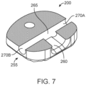
- Figure 7 illustrates a cut-away view of the rasp head.
- a fluid connection 260 oriented axially to the body is formed into the rasp head.
- the fluid connection 260 intersects with and is fluidly connected to lateral passageway 265 which run perpendicular to the body.
- the lateral passageway 265 has a first side 270A and a second side 270B formed respectively on either side of the fluid connection 260.
- the fluid connection and the lateral passageway together form a cavity through the rasp head by which the injection molded material will pass during production of the device.
- the lateral passageway is configured to allow the injection material to flow through.
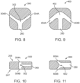
- Figure 8 shows a sectional top view of a rasp head 300 with a "Y" shaped channel having a fluid passageway 302 with sides 304A and 304B at oblique angles from the fluid connection 260.
- Figure 9 shows a sectional top view of a rasp head 400 with an arrow shaped channel having a fluid passageway 402 with sides 404A and 404B at acute angles from the fluid connection 260.
- Figure 10 shows a cross sectional view of a rasp head 500 with a "T" shaped channel with sides 504A and 504B orthogonal to the shaft and fluid passageway 302 spanning from the top side 205 to the bottom side 207 of the rasp head.
- Figure 11 shows a cross sectional view of a rasp head 600 with a "Y" shaped channel with sides 504A and 504B orthogonal to the shaft and fluid passageway 302 spanning from the top side 205 to the bottom side 207 of the rasp head.
- Figures 12 through 14 show side view of several rasp head.
- Figure 12 shows a side view of rasp head 710 with parallel sides 205 and 207.
- Figure 13 shows a side view of a rasp head 720 showing an axis of the rasp head 500 which is parallel or flat to the bottom side 207 and a top side 205 that is tapered relative to the axis of the rasp head.
- Figure 14 shows a side view of rasp head 730 which has a complex shape shown as a convex top side 205 and a convex bottom side 207.
- the center of the rasp head is the height point at height two "h2" and with a lesser height at height one "h1" and height three “h3".
- Figure 14 may be convex or concave on one side and flat on another side.
- Figure 15 illustrates a disposable cutting device 800 with a plastic shaft 110 co-molded to a support collar 802 affixed to a blade 804. Collar end 170B can be seen through lateral passageway 265 which is fluidly connected to fluid connection 260 oriented axially to the shaft and collar.
- Figure 16 illustrates a disposable cutting device 820 with a plastic shaft 110 co-molded to a support collar 822 affixed to a drill 824.
- Collar end 170B can be seen through lateral passageway 265 which is fluidly connected to fluid connection 260 oriented axially to the shaft and collar.
- Figure 17 illustrates a disposable scraping device 830 with a plastic shaft 110 co-molded to a support collar 832 affixed to or formed as part of a scraper 834.
- Collar end 170B can be seen through lateral passageway 265 which is fluidly connected to fluid connection 260 oriented axially to the shaft.
- the lateral passageway is configured to retain injection material in a fashion that fixes the rasp head to the body and prevent rotation of the rasp head on the body within the parameters of intended usage.
Landscapes
- Health & Medical Sciences (AREA)
- Surgery (AREA)
- Life Sciences & Earth Sciences (AREA)
- Biomedical Technology (AREA)
- Medical Informatics (AREA)
- Orthopedic Medicine & Surgery (AREA)
- Oral & Maxillofacial Surgery (AREA)
- Engineering & Computer Science (AREA)
- Dentistry (AREA)
- Heart & Thoracic Surgery (AREA)
- Nuclear Medicine, Radiotherapy & Molecular Imaging (AREA)
- Molecular Biology (AREA)
- Animal Behavior & Ethology (AREA)
- General Health & Medical Sciences (AREA)
- Public Health (AREA)
- Veterinary Medicine (AREA)
- Surgical Instruments (AREA)
Claims (11)
- Einwegschneidewerkzeug, umfassend:einen langgestreckten Formkörper mit einem proximalen Ende (155) und einem distalen Ende (150);einen in der Nähe des distalen Endes ausgebildeten Griffabschnitts (102) und einen Stützschaft (110), der in der Nähe des proximalen Endes ausgebildet ist;einen Raspelkopf (200) mit einer Höhe, einer Oberseite (205), einer Unterseite (207) und einer Fluidverbindung (260);wobei der Stützschaft über Abschnitte des Körpers, der in dem Raspelkopf mitgeformt ist, an dem Raspelkopf (200) angebracht ist;wobei die Abschnitte des Körpers, die in dem Raspelkopf mitgeformt sind, einen geformten Halsbereich (160) umfassen, der innerhalb der Fluidverbindung (260) ausgebildet ist;dadurch gekennzeichnet, dass die Abschnitte des Körpers, die in dem Raspelkopf mitgeformt sind, ferner einen geformten Kragenbereich (165) umfassen, der mit dem Halsbereich verbunden ist und innerhalb eines Durchgangs (265) in dem Raspelkopf ausgebildet ist; wobei der Durchgang (265, 302, 402, 502, 602) mit der Fluidverbindung (260) fluidisch verbunden ist und eine erste Seite (270A) und eine zweite Seite (270B) umfasst, die jeweils auf beiden Seiten der Fluidverbindungen (260) ausgebildet sind.
- Werkzeug nach Anspruch 1, ferner umfassend wenigstens eines von Vertiefungen (105), Erhebungen (104) und nicht homogenen, im Allgemeinen flachen Bereichen (107) auf dem Griffabschnitt.
- Werkzeug nach Anspruch 1, wobei der Durchgang (502) orthogonal und senkrecht zu dem Schaft ist, der sich von der Oberseite zu der Unterseite des Raspelkopfes erstreckt.
- Werkzeug nach Anspruch 1, wobei der Durchgang (402) in einem spitzen Winkel zu dem Schaft verläuft.
- Werkzeug nach Anspruch 1, wobei der Durchgang (302) in einem schiefen Winkel zu dem Schaft verläuft.
- Werkzeug nach Anspruch 1, wobei der Durchgang (602) "Y"-förmig ist und sich von der Oberseite zu der Unterseite des Raspelkopfes erstreckt.
- Werkzeug nach Anspruch 1, wobei wenigstens einer des Raspelkopfes und des Stützschaftes konisch ist.
- Werkzeug nach Anspruch 1, wobei wenigstens eine der Oberseite und der Unterseite des Raspelkopfes parallel zu einer Achse des Raspelkopfes (500) verläuft und die andere Seite relativ zu der Achse des Raspelkopfes abgewinkelt ist.
- Werkzeug nach Anspruch 7, wobei sich der Raspelkopf von einer ersten Höhe "h1" an seinem proximalen Ende (201) zu einer zweiten Höhe "h2" an seinem distalen Ende (202) verjüngt.
- Werkzeug nach Anspruch 7, wobei sich der Raspelkopf von einer ersten Höhe "h1" an seinem proximalen Ende (201) zu einer zweiten Höhe "h2" in seinem mittleren Bereich und zu einer dritten Höhe "h3" an seinem distalen Ende (202) verjüngt.
- Werkzeug nach Anspruch 9, wobei sich der Schaft von einer ersten Querschnittshöhe "sh1" zu einer zweiten Querschnittshöhe "sh2" verjüngt und die zweite Querschnittshöhe im Allgemeinen gleich einer zweiten Höhe "h2" ist.
Applications Claiming Priority (1)
| Application Number | Priority Date | Filing Date | Title |
|---|---|---|---|
| PCT/US2018/028956 WO2019209256A1 (en) | 2018-04-23 | 2018-04-23 | Disposable rasp for medical instruments |
Publications (3)
| Publication Number | Publication Date |
|---|---|
| EP3784151A1 EP3784151A1 (de) | 2021-03-03 |
| EP3784151A4 EP3784151A4 (de) | 2021-12-29 |
| EP3784151B1 true EP3784151B1 (de) | 2025-01-01 |
Family
ID=68294189
Family Applications (1)
| Application Number | Title | Priority Date | Filing Date |
|---|---|---|---|
| EP18916571.5A Active EP3784151B1 (de) | 2018-04-23 | 2018-04-23 | Einwegraspel für medizinische instrumente |
Country Status (3)
| Country | Link |
|---|---|
| US (1) | US11723674B2 (de) |
| EP (1) | EP3784151B1 (de) |
| WO (1) | WO2019209256A1 (de) |
Family Cites Families (10)
| Publication number | Priority date | Publication date | Assignee | Title |
|---|---|---|---|---|
| US3748736A (en) * | 1971-12-13 | 1973-07-31 | S Eisen | Surgical knife |
| US4587964A (en) * | 1985-02-05 | 1986-05-13 | Zimmer, Inc. | Rasp tool |
| ES2271978T3 (es) | 1998-06-19 | 2007-04-16 | Imt Integral Medizintechnik Ag | Escofina desechable para huesos y procedimiento para su fabricacion. |
| US6436101B1 (en) | 1999-10-13 | 2002-08-20 | James S. Hamada | Rasp for use in spine surgery |
| FR2847453B1 (fr) * | 2002-11-22 | 2005-09-23 | Jean Francois Biegun | Ancillaires, notamment rape ou bloc de coupe, a usage unique, kit comportant des ancillaires et procede de fabrication |
| US20060229627A1 (en) * | 2004-10-29 | 2006-10-12 | Hunt Margaret M | Variable angle spinal surgery instrument |
| EP2135568B1 (de) * | 2004-06-21 | 2011-12-07 | Straumann Holding AG | Verfahren zur Herstellung von Einwegdrehschneidwerkzeugen und Einwegdrehwerkzeug für dentale oder medizinische Anwendungen |
| US9375221B2 (en) * | 2008-12-29 | 2016-06-28 | Depuy (Ireland) | Orthopaedic cutting block having a chemically etched metal insert |
| US20100262146A1 (en) * | 2009-04-09 | 2010-10-14 | Howmedica Osteonics Corp. | Disposable bone cutting instrument |
| US9101370B2 (en) * | 2010-06-11 | 2015-08-11 | Greatbatch Ltd. | Disposable surgical cutter for shaping the head of a femur |
-
2018
- 2018-04-23 WO PCT/US2018/028956 patent/WO2019209256A1/en not_active Ceased
- 2018-04-23 US US17/050,396 patent/US11723674B2/en active Active
- 2018-04-23 EP EP18916571.5A patent/EP3784151B1/de active Active
Also Published As
| Publication number | Publication date |
|---|---|
| WO2019209256A1 (en) | 2019-10-31 |
| US20210052287A1 (en) | 2021-02-25 |
| US11723674B2 (en) | 2023-08-15 |
| EP3784151A4 (de) | 2021-12-29 |
| EP3784151A1 (de) | 2021-03-03 |
Similar Documents
| Publication | Publication Date | Title |
|---|---|---|
| JP4299668B2 (ja) | 手術用リーマのための着脱可能なリーミング・ヘッド | |
| JP6017759B2 (ja) | カニューレ | |
| CN104039249B (zh) | 植入专用钻头 | |
| US20100095487A1 (en) | Gripping sleeve device for precision instruments | |
| AU2020276042B2 (en) | A set of tools for installing an implant | |
| EP2962649B1 (de) | Orthopädischer antrieb | |
| US8535316B2 (en) | Hollow reamer for medical applications | |
| US20090036991A1 (en) | Radial Head Replacement System | |
| US20110208199A1 (en) | Prosthesis Removal Cutting Guide, Cutting Tool and Method | |
| US12226116B2 (en) | Ultrasonic tip with protrusion defining a preaspiration hole | |
| US20120029294A1 (en) | Cannula | |
| US20250169919A1 (en) | Dental Implement | |
| US20250235327A1 (en) | Tools and methods for arthroscopic surgery | |
| EP3784151B1 (de) | Einwegraspel für medizinische instrumente | |
| US20260020866A1 (en) | Cutting elements | |
| EP3116415B1 (de) | Vorrichtung zur entnahme eines intramedullären autotransplantats | |
| US20020072034A1 (en) | Ultrasonic surgical dental tool having a chisel tip | |
| US10758319B2 (en) | Surgical dental tool | |
| CN210019699U (zh) | 手术路径定位器及手术器械 | |
| EP3917416B1 (de) | Verbinder für ein chirurgisches handstück | |
| US20040078041A1 (en) | Apparatus for removing an osteophyte | |
| US20080051813A1 (en) | Adapter Sleeve | |
| RU2167618C2 (ru) | Иглосверло для обработки костной ткани | |
| US20170071612A1 (en) | Surgical metal debris reduction system |
Legal Events
| Date | Code | Title | Description |
|---|---|---|---|
| STAA | Information on the status of an ep patent application or granted ep patent |
Free format text: STATUS: THE INTERNATIONAL PUBLICATION HAS BEEN MADE |
|
| PUAI | Public reference made under article 153(3) epc to a published international application that has entered the european phase |
Free format text: ORIGINAL CODE: 0009012 |
|
| STAA | Information on the status of an ep patent application or granted ep patent |
Free format text: STATUS: REQUEST FOR EXAMINATION WAS MADE |
|
| 17P | Request for examination filed |
Effective date: 20201123 |
|
| AK | Designated contracting states |
Kind code of ref document: A1 Designated state(s): AL AT BE BG CH CY CZ DE DK EE ES FI FR GB GR HR HU IE IS IT LI LT LU LV MC MK MT NL NO PL PT RO RS SE SI SK SM TR |
|
| AX | Request for extension of the european patent |
Extension state: BA ME |
|
| DAV | Request for validation of the european patent (deleted) | ||
| DAX | Request for extension of the european patent (deleted) | ||
| A4 | Supplementary search report drawn up and despatched |
Effective date: 20211126 |
|
| RIC1 | Information provided on ipc code assigned before grant |
Ipc: A61B 17/3211 20060101ALI20211122BHEP Ipc: A61B 17/16 20060101AFI20211122BHEP |
|
| GRAP | Despatch of communication of intention to grant a patent |
Free format text: ORIGINAL CODE: EPIDOSNIGR1 |
|
| STAA | Information on the status of an ep patent application or granted ep patent |
Free format text: STATUS: GRANT OF PATENT IS INTENDED |
|
| INTG | Intention to grant announced |
Effective date: 20241018 |
|
| GRAS | Grant fee paid |
Free format text: ORIGINAL CODE: EPIDOSNIGR3 |
|
| GRAA | (expected) grant |
Free format text: ORIGINAL CODE: 0009210 |
|
| STAA | Information on the status of an ep patent application or granted ep patent |
Free format text: STATUS: THE PATENT HAS BEEN GRANTED |
|
| AK | Designated contracting states |
Kind code of ref document: B1 Designated state(s): AL AT BE BG CH CY CZ DE DK EE ES FI FR GB GR HR HU IE IS IT LI LT LU LV MC MK MT NL NO PL PT RO RS SE SI SK SM TR |
|
| REG | Reference to a national code |
Ref country code: GB Ref legal event code: FG4D |
|
| REG | Reference to a national code |
Ref country code: DE Ref legal event code: R096 Ref document number: 602018078260 Country of ref document: DE |
|
| REG | Reference to a national code |
Ref country code: CH Ref legal event code: EP |
|
| REG | Reference to a national code |
Ref country code: IE Ref legal event code: FG4D |
|
| REG | Reference to a national code |
Ref country code: LT Ref legal event code: MG9D |
|
| REG | Reference to a national code |
Ref country code: NL Ref legal event code: MP Effective date: 20250101 |
|
| REG | Reference to a national code |
Ref country code: AT Ref legal event code: MK05 Ref document number: 1755449 Country of ref document: AT Kind code of ref document: T Effective date: 20250101 |
|
| PG25 | Lapsed in a contracting state [announced via postgrant information from national office to epo] |
Ref country code: NL Free format text: LAPSE BECAUSE OF FAILURE TO SUBMIT A TRANSLATION OF THE DESCRIPTION OR TO PAY THE FEE WITHIN THE PRESCRIBED TIME-LIMIT Effective date: 20250101 |
|
| PG25 | Lapsed in a contracting state [announced via postgrant information from national office to epo] |
Ref country code: FI Free format text: LAPSE BECAUSE OF FAILURE TO SUBMIT A TRANSLATION OF THE DESCRIPTION OR TO PAY THE FEE WITHIN THE PRESCRIBED TIME-LIMIT Effective date: 20250101 |
|
| PG25 | Lapsed in a contracting state [announced via postgrant information from national office to epo] |
Ref country code: PL Free format text: LAPSE BECAUSE OF FAILURE TO SUBMIT A TRANSLATION OF THE DESCRIPTION OR TO PAY THE FEE WITHIN THE PRESCRIBED TIME-LIMIT Effective date: 20250101 |
|
| PGFP | Annual fee paid to national office [announced via postgrant information from national office to epo] |
Ref country code: DE Payment date: 20250305 Year of fee payment: 8 |
|
| PG25 | Lapsed in a contracting state [announced via postgrant information from national office to epo] |
Ref country code: ES Free format text: LAPSE BECAUSE OF FAILURE TO SUBMIT A TRANSLATION OF THE DESCRIPTION OR TO PAY THE FEE WITHIN THE PRESCRIBED TIME-LIMIT Effective date: 20250101 |
|
| PG25 | Lapsed in a contracting state [announced via postgrant information from national office to epo] |
Ref country code: IS Free format text: LAPSE BECAUSE OF FAILURE TO SUBMIT A TRANSLATION OF THE DESCRIPTION OR TO PAY THE FEE WITHIN THE PRESCRIBED TIME-LIMIT Effective date: 20250501 Ref country code: NO Free format text: LAPSE BECAUSE OF FAILURE TO SUBMIT A TRANSLATION OF THE DESCRIPTION OR TO PAY THE FEE WITHIN THE PRESCRIBED TIME-LIMIT Effective date: 20250401 |
|
| PG25 | Lapsed in a contracting state [announced via postgrant information from national office to epo] |
Ref country code: HR Free format text: LAPSE BECAUSE OF FAILURE TO SUBMIT A TRANSLATION OF THE DESCRIPTION OR TO PAY THE FEE WITHIN THE PRESCRIBED TIME-LIMIT Effective date: 20250101 |
|
| PG25 | Lapsed in a contracting state [announced via postgrant information from national office to epo] |
Ref country code: PT Free format text: LAPSE BECAUSE OF FAILURE TO SUBMIT A TRANSLATION OF THE DESCRIPTION OR TO PAY THE FEE WITHIN THE PRESCRIBED TIME-LIMIT Effective date: 20250502 Ref country code: LV Free format text: LAPSE BECAUSE OF FAILURE TO SUBMIT A TRANSLATION OF THE DESCRIPTION OR TO PAY THE FEE WITHIN THE PRESCRIBED TIME-LIMIT Effective date: 20250101 |
|
| PG25 | Lapsed in a contracting state [announced via postgrant information from national office to epo] |
Ref country code: GR Free format text: LAPSE BECAUSE OF FAILURE TO SUBMIT A TRANSLATION OF THE DESCRIPTION OR TO PAY THE FEE WITHIN THE PRESCRIBED TIME-LIMIT Effective date: 20250402 Ref country code: BG Free format text: LAPSE BECAUSE OF FAILURE TO SUBMIT A TRANSLATION OF THE DESCRIPTION OR TO PAY THE FEE WITHIN THE PRESCRIBED TIME-LIMIT Effective date: 20250101 |
|
| PG25 | Lapsed in a contracting state [announced via postgrant information from national office to epo] |
Ref country code: AT Free format text: LAPSE BECAUSE OF FAILURE TO SUBMIT A TRANSLATION OF THE DESCRIPTION OR TO PAY THE FEE WITHIN THE PRESCRIBED TIME-LIMIT Effective date: 20250101 |
|
| PG25 | Lapsed in a contracting state [announced via postgrant information from national office to epo] |
Ref country code: CZ Free format text: LAPSE BECAUSE OF FAILURE TO SUBMIT A TRANSLATION OF THE DESCRIPTION OR TO PAY THE FEE WITHIN THE PRESCRIBED TIME-LIMIT Effective date: 20250101 |
|
| PG25 | Lapsed in a contracting state [announced via postgrant information from national office to epo] |
Ref country code: SE Free format text: LAPSE BECAUSE OF FAILURE TO SUBMIT A TRANSLATION OF THE DESCRIPTION OR TO PAY THE FEE WITHIN THE PRESCRIBED TIME-LIMIT Effective date: 20250101 |
|
| REG | Reference to a national code |
Ref country code: DE Ref legal event code: R097 Ref document number: 602018078260 Country of ref document: DE |
|
| PG25 | Lapsed in a contracting state [announced via postgrant information from national office to epo] |
Ref country code: SM Free format text: LAPSE BECAUSE OF FAILURE TO SUBMIT A TRANSLATION OF THE DESCRIPTION OR TO PAY THE FEE WITHIN THE PRESCRIBED TIME-LIMIT Effective date: 20250101 |
|
| PG25 | Lapsed in a contracting state [announced via postgrant information from national office to epo] |
Ref country code: DK Free format text: LAPSE BECAUSE OF FAILURE TO SUBMIT A TRANSLATION OF THE DESCRIPTION OR TO PAY THE FEE WITHIN THE PRESCRIBED TIME-LIMIT Effective date: 20250101 |
|
| PG25 | Lapsed in a contracting state [announced via postgrant information from national office to epo] |
Ref country code: IT Free format text: LAPSE BECAUSE OF FAILURE TO SUBMIT A TRANSLATION OF THE DESCRIPTION OR TO PAY THE FEE WITHIN THE PRESCRIBED TIME-LIMIT Effective date: 20250101 |
|
| PG25 | Lapsed in a contracting state [announced via postgrant information from national office to epo] |
Ref country code: EE Free format text: LAPSE BECAUSE OF FAILURE TO SUBMIT A TRANSLATION OF THE DESCRIPTION OR TO PAY THE FEE WITHIN THE PRESCRIBED TIME-LIMIT Effective date: 20250101 |
|
| PG25 | Lapsed in a contracting state [announced via postgrant information from national office to epo] |
Ref country code: RO Free format text: LAPSE BECAUSE OF FAILURE TO SUBMIT A TRANSLATION OF THE DESCRIPTION OR TO PAY THE FEE WITHIN THE PRESCRIBED TIME-LIMIT Effective date: 20250101 |
|
| PG25 | Lapsed in a contracting state [announced via postgrant information from national office to epo] |
Ref country code: SK Free format text: LAPSE BECAUSE OF FAILURE TO SUBMIT A TRANSLATION OF THE DESCRIPTION OR TO PAY THE FEE WITHIN THE PRESCRIBED TIME-LIMIT Effective date: 20250101 |
|
| PLBE | No opposition filed within time limit |
Free format text: ORIGINAL CODE: 0009261 |
|
| STAA | Information on the status of an ep patent application or granted ep patent |
Free format text: STATUS: NO OPPOSITION FILED WITHIN TIME LIMIT |
|
| REG | Reference to a national code |
Ref country code: CH Ref legal event code: L10 Free format text: ST27 STATUS EVENT CODE: U-0-0-L10-L00 (AS PROVIDED BY THE NATIONAL OFFICE) Effective date: 20251112 |
|
| REG | Reference to a national code |
Ref country code: CH Ref legal event code: H13 Free format text: ST27 STATUS EVENT CODE: U-0-0-H10-H13 (AS PROVIDED BY THE NATIONAL OFFICE) Effective date: 20251125 |
|
| 26N | No opposition filed |
Effective date: 20251002 |
|
| PG25 | Lapsed in a contracting state [announced via postgrant information from national office to epo] |
Ref country code: LU Free format text: LAPSE BECAUSE OF NON-PAYMENT OF DUE FEES Effective date: 20250423 |
|
| PG25 | Lapsed in a contracting state [announced via postgrant information from national office to epo] |
Ref country code: MC Free format text: LAPSE BECAUSE OF FAILURE TO SUBMIT A TRANSLATION OF THE DESCRIPTION OR TO PAY THE FEE WITHIN THE PRESCRIBED TIME-LIMIT Effective date: 20250101 |
|
| REG | Reference to a national code |
Ref country code: BE Ref legal event code: MM Effective date: 20250430 |
|
| PG25 | Lapsed in a contracting state [announced via postgrant information from national office to epo] |
Ref country code: BE Free format text: LAPSE BECAUSE OF NON-PAYMENT OF DUE FEES Effective date: 20250430 |
|
| PG25 | Lapsed in a contracting state [announced via postgrant information from national office to epo] |
Ref country code: CH Free format text: LAPSE BECAUSE OF NON-PAYMENT OF DUE FEES Effective date: 20250430 |
|
| PGFP | Annual fee paid to national office [announced via postgrant information from national office to epo] |
Ref country code: GB Payment date: 20260312 Year of fee payment: 9 |
|
| PG25 | Lapsed in a contracting state [announced via postgrant information from national office to epo] |
Ref country code: IE Free format text: LAPSE BECAUSE OF NON-PAYMENT OF DUE FEES Effective date: 20250423 |
|
| PGFP | Annual fee paid to national office [announced via postgrant information from national office to epo] |
Ref country code: FR Payment date: 20260309 Year of fee payment: 9 |