EP3784103B1 - Floor treatment machine - Google Patents
Floor treatment machine Download PDFInfo
- Publication number
- EP3784103B1 EP3784103B1 EP19719614.0A EP19719614A EP3784103B1 EP 3784103 B1 EP3784103 B1 EP 3784103B1 EP 19719614 A EP19719614 A EP 19719614A EP 3784103 B1 EP3784103 B1 EP 3784103B1
- Authority
- EP
- European Patent Office
- Prior art keywords
- wheel means
- treatment machine
- floor treatment
- base portion
- machine
- Prior art date
- Legal status (The legal status is an assumption and is not a legal conclusion. Google has not performed a legal analysis and makes no representation as to the accuracy of the status listed.)
- Active
Links
- 238000004140 cleaning Methods 0.000 claims description 7
- 239000007788 liquid Substances 0.000 claims description 7
- 239000012530 fluid Substances 0.000 claims description 6
- 238000005200 wet scrubbing Methods 0.000 claims description 2
- 238000005201 scrubbing Methods 0.000 description 5
- XLYOFNOQVPJJNP-UHFFFAOYSA-N water Substances O XLYOFNOQVPJJNP-UHFFFAOYSA-N 0.000 description 4
- 230000008901 benefit Effects 0.000 description 2
- 230000009977 dual effect Effects 0.000 description 2
- 238000005498 polishing Methods 0.000 description 2
- 230000001141 propulsive effect Effects 0.000 description 2
- 239000002351 wastewater Substances 0.000 description 2
- 235000004443 Ricinus communis Nutrition 0.000 description 1
- 230000008878 coupling Effects 0.000 description 1
- 238000010168 coupling process Methods 0.000 description 1
- 238000005859 coupling reaction Methods 0.000 description 1
- 230000000694 effects Effects 0.000 description 1
- 239000013536 elastomeric material Substances 0.000 description 1
- 239000000835 fiber Substances 0.000 description 1
- 238000010408 sweeping Methods 0.000 description 1
Images


Classifications
-
- A—HUMAN NECESSITIES
- A47—FURNITURE; DOMESTIC ARTICLES OR APPLIANCES; COFFEE MILLS; SPICE MILLS; SUCTION CLEANERS IN GENERAL
- A47L—DOMESTIC WASHING OR CLEANING; SUCTION CLEANERS IN GENERAL
- A47L11/00—Machines for cleaning floors, carpets, furniture, walls, or wall coverings
- A47L11/02—Floor surfacing or polishing machines
- A47L11/04—Floor surfacing or polishing machines hand-driven
- A47L11/08—Floor surfacing or polishing machines hand-driven with rotating tools
-
- A—HUMAN NECESSITIES
- A47—FURNITURE; DOMESTIC ARTICLES OR APPLIANCES; COFFEE MILLS; SPICE MILLS; SUCTION CLEANERS IN GENERAL
- A47L—DOMESTIC WASHING OR CLEANING; SUCTION CLEANERS IN GENERAL
- A47L11/00—Machines for cleaning floors, carpets, furniture, walls, or wall coverings
- A47L11/26—Floor-scrubbing machines, hand-driven
-
- A—HUMAN NECESSITIES
- A47—FURNITURE; DOMESTIC ARTICLES OR APPLIANCES; COFFEE MILLS; SPICE MILLS; SUCTION CLEANERS IN GENERAL
- A47L—DOMESTIC WASHING OR CLEANING; SUCTION CLEANERS IN GENERAL
- A47L11/00—Machines for cleaning floors, carpets, furniture, walls, or wall coverings
- A47L11/40—Parts or details of machines not provided for in groups A47L11/02 - A47L11/38, or not restricted to one of these groups, e.g. handles, arrangements of switches, skirts, buffers, levers
- A47L11/4072—Arrangement of castors or wheels
-
- A—HUMAN NECESSITIES
- A47—FURNITURE; DOMESTIC ARTICLES OR APPLIANCES; COFFEE MILLS; SPICE MILLS; SUCTION CLEANERS IN GENERAL
- A47L—DOMESTIC WASHING OR CLEANING; SUCTION CLEANERS IN GENERAL
- A47L11/00—Machines for cleaning floors, carpets, furniture, walls, or wall coverings
- A47L11/40—Parts or details of machines not provided for in groups A47L11/02 - A47L11/38, or not restricted to one of these groups, e.g. handles, arrangements of switches, skirts, buffers, levers
- A47L11/4075—Handles; levers
-
- A—HUMAN NECESSITIES
- A47—FURNITURE; DOMESTIC ARTICLES OR APPLIANCES; COFFEE MILLS; SPICE MILLS; SUCTION CLEANERS IN GENERAL
- A47L—DOMESTIC WASHING OR CLEANING; SUCTION CLEANERS IN GENERAL
- A47L11/00—Machines for cleaning floors, carpets, furniture, walls, or wall coverings
- A47L11/40—Parts or details of machines not provided for in groups A47L11/02 - A47L11/38, or not restricted to one of these groups, e.g. handles, arrangements of switches, skirts, buffers, levers
- A47L11/4091—Storing or parking devices, arrangements therefor; Means allowing transport of the machine when it is not being used
-
- B—PERFORMING OPERATIONS; TRANSPORTING
- B24—GRINDING; POLISHING
- B24B—MACHINES, DEVICES, OR PROCESSES FOR GRINDING OR POLISHING; DRESSING OR CONDITIONING OF ABRADING SURFACES; FEEDING OF GRINDING, POLISHING, OR LAPPING AGENTS
- B24B7/00—Machines or devices designed for grinding plane surfaces on work, including polishing plane glass surfaces; Accessories therefor
- B24B7/10—Single-purpose machines or devices
- B24B7/18—Single-purpose machines or devices for grinding floorings, walls, ceilings or the like
- B24B7/186—Single-purpose machines or devices for grinding floorings, walls, ceilings or the like with disc-type tools
Definitions
- the present invention relates to the field of floor treatment machines for scrubbing, polishing, sanding or burnishing floors.
- floor treatment machines for scrubbing, polishing, sanding or burnishing floors.
- one or more driven rotatable work heads (such as scrubbing brushes) are provided for agitating the floor surface.
- the invention relates to a walk-behind machine provided with a handle for steering and guiding the machine as it travels over a floor surface.
- EP2832277 discloses a walk-behind wet floor scrubber have two side-by-side work heads, each comprising disc-shaped floor brushes. There is a trailing squeegee and associated suction drive and reservoir for collecting liquid from the floor surface. The brushes support the weight of the machine and counter-rotate to provide propulsive force.
- the suction drive is disposed on a handle portion of the machine, along with a clean water reservoir for feeding a cleaning-liquid dispenser.
- the hand has dual pivot axes permitting up/down handle movement as well as side-to-side. A problem with these machines is that they are not very directional stable.
- US2949619A (Holt William ) discloses a walk-behind floor scrubbing machine on which the preamble of claim 1 is based. It has a disc-shaped work head supported at a rear end region thereof by a pair of side-by-side wheels disposed at the base of an upstanding handle portion.
- the present invention seeks to provide a floor treatment machine which has better directional control, especially straight line and cornering control.
- a floor treatment machine (preferably walk-behind) comprising:
- the wheel means may comprise a wheel, roller or ball, singular or co-axial adjacent pairs. Preferably there is a single wheel, roller or ball, most conveniently disposed at a lower region of the handle portion.
- the wheel means may preferably have a fixed transverse axis of rotation (when placed on the floor). In other words there is no caster wheeling.
- the wheel or roller may however be adapted to tilt into a turn (so it tilts about an axis coaxial with the direction of travel).
- the linkage which couples the wheel means and the machine base portion may comprise a pitch pivotal connection to the wheel means. This connection may be coaxial with the wheel means axis of rotation. Furthermore, or in the alternative, the linkage may comprise a pitch pivotal connection to the base portion. Preferably the linkage has both such pivots so as to permit vertical travel of the base portion with respect to the wheel means.
- the linkage may conveniently comprise one, or preferably two side by side struts, with a pivoted connection to the base portion at one end of the strut(s) and a pivoted connection to the wheel means at the other.
- Said one or more rotatable work heads preferably supports the base portion on the floor surface with the linkage permitting floating vertical travel of the work heads with respect to the wheel means.
- a lower region of the handle portion is attached to the wheel means via an articulated joint which permits up/down pivoting of the handle about the joint.
- the articulated joint permits side-to-side pivoting of the handle about the joint.
- the up/down pivot of the articulated joint may be provided at a pivot which is co-axial with the wheel means axis of rotation.
- the side-to-side pivot of the articulated joint may be provided at a location vertically spaced apart from the up/down pivot.
- the articulated joint may comprise a yoke which accommodates a wheel, roller or ball of the wheel means, which yoke preferably pivots about the wheel rotation axis.
- the side-to-side pivot may be disposed on an upper bridging portion of the yoke.
- the side-to-side pivot may comprise a U-section bracket rotated 90 degrees with respect to the yoke and which receives a lower end of the handle, with a pivot pin bridging the bracket cheeks.
- the base portion and associated work head(s) may be disposed at a front region of the machine.
- the wheel means may be disposed aft of the work head(s) and base portion with the linkage coupling extending between the wheel means and base portion (preferably generally centrally of machine or a centre region of the base portion).
- the machine is a wet scrubbing machine. It may be provided with a cleaning fluid reservoir and cleaning fluid delivery outlet.
- a squeegee liquid collector is preferably provided which is coupled to the machine by a trailing linkage.
- the linkage may permit up/down travel of the squeegee collector with respect to the wheels means.
- the trailing linkage is preferably pivotably coupled to the wheel means co-axially with the transverse axis of the wheel means.
- the machine may be provided with a squeegee suction drive and dirty liquid collection reservoir.
- the squeegee collector may be able to adopt a transport (or storage) configuration in which the squeegee is pivoted down and depending from the trailing linkage (with the wheels/rollers on the floor), or folded up vertically away from the floor.
- the wheels may simply be for supporting the squeegee collector.
- Forward propulsion of the machine is preferably provided by work head rotation.
- the direction of rotation controls forward or backward movement.
- the propulsion can be provided by using two work heads which counter-rotate.
- the user can roll the handle slightly to roll the work head lightly which will cause improved traction on one side of the work head, which will induce forward propulsion if that side is the returning rotational side.
- the drive means may comprise one or more electric motors carried by the base portion and coupled to the work head or heads.
- Other arrangements are possible, such as a single motor which drives both heads via a pulley, chain or gear train.
- a single motor for each head is preferred.
- the twin motors are configured and/or controlled to cause the work heads to counter rotate with respect to one another, thereby to provide a propulsive force.
- Scrubber brush driven machines are well known in the art. For example a single brush may be induced to drive by tilting the machine (base portion) onto the retreating side of a rotating disc-shaped, floor facing, work head.
- the machine of the invention is preferably a walk-behind machine.
- a distal end of the handle portion may be provided with a transversely oriented handle bar for the user to grip with a hand on each side of the bar.
- the handlebar may be provided with a speed control lever and cleaning fluid dispensing actuator.
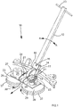
- a floor scrubber dryer machine in accordance with the present invention is shown generally as 10.
- the machine comprises an elongate rectangular section handle portion 12.
- the handle portion 12 comprises a top end region and a bottom end region.
- a handlebar 13 is transversely mounted via a bore at the top end region of the handle portion 12.
- a control unit (not shown) is also provided at the top end region. During use the user walks behind the machine and guides it over the floor surface to be cleaned using the handlebar 13.
- the bottom end region of the handle portion 12 is pivotally attached between upstanding ear portions of a U-section mounting bracket 14.
- the pivot is oriented fore-aft to enable side-to-side rotation of the handle portion relative to the bracket 14 about a pivot axis 15, as shown in the arrows A, A' of Figure 3 .
- the axis 15 is substantially perpendicular to the length of the handle portion 2 and permits the handle to be swung transversely from side to side about the bottom end region.
- the bracket 14 has a lower region which is configured as a fork or yoke 17 formed by two spaced apart downwardly extending cheek plates.
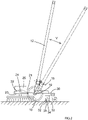
- a guide wheel 18 is located between the cheek plates and mounted for rotation about an axle 19, as shown in Figure 2 .
- the axle permits the top end region of the handle to be pivoted forward/backwards, up/down through an arc V around the transverse axis provided by the axle 19.
- the wheel 18 is arranged to enable rotation about a single axis and is otherwise fixed in position.
- the wheel 18 may be configured to lean either left or right into a turn as a user manoeuvres the machine 18 around the floor surface. This can improve the handling of the machine 10.
- the same leaning could apply to other wheel means such as rollers or balls
- a pair of elongate, forwardly extending, spaced apart mounting struts 21 are pivotally attached at rear end regions thereof to opposite respective sides the wheel axle 19 projecting from either side of the wheel 18. Front end regions of each strut are attached to a pair of upstanding, spaced apart generally triangular brackets 22 formed on a rectangular work base plate 23. The attachment is made via a pivot connection 24 having a transverse axis of rotation.
- the base portion supports thereon two electric motors side by side which are a left scrubber electric motor 25 and a right scrubber electric motor 26.
- a left scrubber brush 27 and a right scrubber brush 28 are attached under the base portion 23 to depending respective rotors (not shown) of the electric motors.
- the left scrubber and right scrubber are mounted to the rotors using conventional means such as a hub or chuck (not shown).
- Each scrubber brush 27, 28 comprises a disc shaped base portion 29, and an annular array of fibre brushes 30, fixed an underside of the base portion.
- the scrubber brushes are arranged to enable rotation in opposite directions and about parallel vertical axes as shown in Figure 1 , which can provide forward or rearward propulsion
- the collector 30 comprises an elongate lenticular form collector arm 31.
- a forward collector blade 32 and a rear collector blade 33 are mounted below the collector arm 31 such that both the forward blade 32 and rear blade 33 are able to be in contact with a floor when the machine 1 is in normal use.
- the collector blades 32, 33 are made of an elastomeric material, as is conventional.
- the squeegee interior (chamber 34) defined between the forward and rear blades is in fluid communication with a suction drive (not shown) which may be mounted on the handle 12 or the base portion 23 so as to entrain and draw-up waste water that has passed through the scrubbers brushes. Waste water drawn-up from the suction chamber 34 is stored in a tank (not shown).
- the suction drive and tank may be positioned above the scrubber mount 11, or on the handle portion 2, or at another convenient location on the machine 1.
- a left rear wheel assembly 35 and a right rear wheel assembly 36 are both mounted to the collector arm 31 and projecting rearwardly and co-terminously.
- Each rear wheel assembly comprises a rear castor wheel.
- the squeegee collector is attached to the wheel axis 19 by a pair of transversely spaced apart rearwardly extending struts 38, so that the collector can pivot up/down around the wheels axis.
- the squeegee collector can thus be folded up or down for storage. Furthermore the collector can, when in use, follow floor undulations without losing suction as the machine move forwards.
- Figures 4a-4d show various configurations of the handle portion 12, the base portion 23 and the wheel yoke 17.
- Figure 4a shows a configuration in which the handle portion 12 in the left-to-right position and at an angle with the floor surface.
- the configuration of Figure 4a is similar to that shown in Figure 1 .
- Figure 4b shows a configuration in which the handle portion 12 has been rotated such that the handlebar 13 has moved to the left.
- Figure 4b represents a configuration where a user is turning the machine 10 to the left.
- Figure 4c shows a configuration in which the handle portion 12 is upright such that the handlebar 13 is parallel with the floor surface. The handle portion 12 has then been rotated such that the handlebar 13 has moved the left.
- Figure 4d shows a configuration in which the handle portion 2 has been rotated such that the handlebar 13 is now positioned forwards of the scrubbers 27, 28.
- the machine of the present invention has several unique features and benefits.
- a further contact point arranged between the scrubber base portion and the floor so the base portion remains stably horizontal to the floor supported by this contact point and the rotating brushes.
- the wheel 18 rotates as the machine moves forwards but provides a fixed, set distance from the floor to the base portion.
- This arrangement gives better handling than prior art machines without the guide wheel because the guide wheel acts to prevent yawing of the whole machine base, giving a more positive stable control. It gives longitudinal stability by virtue of its fixed transverse rotational axis, and helps to prevent skidding or slipping of the machine base over the surface of the floor.
- Another advantage of the guide wheel is the ability for weight to be carried by the handle over the guide wheel without this weight directly acting on the scrubber brushes to cause the brush filaments to bend excessively or interfere with smooth rotation and scrubbing.
- heavy machine elements such as clean water or dirty water collection reservoirs can be carried attached to the handle.
- suction drive motors or batteries could be carried by, or attached to the handle (preferably in the lower region so as to ensure that weight is transferred to the wheel rather than shared excessively with handle held by the user-operator).
- the machine provides a stable scrubbing deck which has a performance unaffected by weight changes due to cleaning liquid use or collection.
Description
- The present invention relates to the field of floor treatment machines for scrubbing, polishing, sanding or burnishing floors. In these machines one or more driven rotatable work heads (such as scrubbing brushes) are provided for agitating the floor surface. In particular the invention relates to a walk-behind machine provided with a handle for steering and guiding the machine as it travels over a floor surface.
-
EP2832277 (i-mop GmbH ) discloses a walk-behind wet floor scrubber have two side-by-side work heads, each comprising disc-shaped floor brushes. There is a trailing squeegee and associated suction drive and reservoir for collecting liquid from the floor surface. The brushes support the weight of the machine and counter-rotate to provide propulsive force. The suction drive is disposed on a handle portion of the machine, along with a clean water reservoir for feeding a cleaning-liquid dispenser. The hand has dual pivot axes permitting up/down handle movement as well as side-to-side. A problem with these machines is that they are not very directional stable. This arises from the lack of guiding constraint provided by rotating work heads and by the dual pivoted handle which permits the user to make easy side-to -side sweeping movements along arcs, but is less suited to straight line movement of the machine methodically over a surface to be cleaned. In addition, these machines are difficult to turn sharply to go around corners or obstructions. The effort to control the machines can tire the operator and limit productivity. -
US2949619A (Holt William ) discloses a walk-behind floor scrubbing machine on which the preamble of claim 1 is based. It has a disc-shaped work head supported at a rear end region thereof by a pair of side-by-side wheels disposed at the base of an upstanding handle portion. - The present invention seeks to provide a floor treatment machine which has better directional control, especially straight line and cornering control. These aims and others are met by the present invention in its various aspects, as will be evident from the following description.
- According to one aspect of the present invention there is provided a floor treatment machine (preferably walk-behind) comprising:
- a base portion provided with and supported by at least one rotatable work head for treating the floor,
- a handle portion for steering or guiding the machine along a working direction of travel and adapted to be pivotable with respect to the base portion,
- drive means for rotating the work head with respect to the base portion,
- floor-engaging wheel means for supporting the handle portion, the wheel means having a substantially transverse axis of rotation so as to permit travel in the working direction, the wheel means being coupled to the base portion by a linkage which permits vertical travel of the base portion and work head or heads with respect to the wheel means, but which provides transverse constraint to limit or prevent yawing of the base portion with respect to the wheel means,
- wherein a lower region of the handle portion is pivotably connected to the wheel means via an articulated joint which permits up/down pivoting of the handle about the joint and side-to-side pivoting of the handle about the joint, the arrangement being such that the handle portion may be manipulated to act on the wheel means so as to yaw steer the wheel means about a yaw axis defined by the floor-engaging contact of the wheel means, the yawing of the wheel means causing the base portion to yaw in response to yaw steering.
- The wheel means may comprise a wheel, roller or ball, singular or co-axial adjacent pairs. Preferably there is a single wheel, roller or ball, most conveniently disposed at a lower region of the handle portion. The wheel means may preferably have a fixed transverse axis of rotation (when placed on the floor). In other words there is no caster wheeling. The wheel or roller may however be adapted to tilt into a turn (so it tilts about an axis coaxial with the direction of travel).
- The linkage which couples the wheel means and the machine base portion may comprise a pitch pivotal connection to the wheel means. This connection may be coaxial with the wheel means axis of rotation. Furthermore, or in the alternative, the linkage may comprise a pitch pivotal connection to the base portion. Preferably the linkage has both such pivots so as to permit vertical travel of the base portion with respect to the wheel means. The linkage may conveniently comprise one, or preferably two side by side struts, with a pivoted connection to the base portion at one end of the strut(s) and a pivoted connection to the wheel means at the other.
- Said one or more rotatable work heads preferably supports the base portion on the floor surface with the linkage permitting floating vertical travel of the work heads with respect to the wheel means. A lower region of the handle portion is attached to the wheel means via an articulated joint which permits up/down pivoting of the handle about the joint. The articulated joint permits side-to-side pivoting of the handle about the joint. The up/down pivot of the articulated joint may be provided at a pivot which is co-axial with the wheel means axis of rotation. The side-to-side pivot of the articulated joint may be provided at a location vertically spaced apart from the up/down pivot. The articulated joint may comprise a yoke which accommodates a wheel, roller or ball of the wheel means, which yoke preferably pivots about the wheel rotation axis. The side-to-side pivot may be disposed on an upper bridging portion of the yoke. The side-to-side pivot may comprise a U-section bracket rotated 90 degrees with respect to the yoke and which receives a lower end of the handle, with a pivot pin bridging the bracket cheeks.
- The base portion and associated work head(s) may be disposed at a front region of the machine. The wheel means may be disposed aft of the work head(s) and base portion with the linkage coupling extending between the wheel means and base portion (preferably generally centrally of machine or a centre region of the base portion).
- In a preferred aspect of the invention, the machine is a wet scrubbing machine. It may be provided with a cleaning fluid reservoir and cleaning fluid delivery outlet. A squeegee liquid collector is preferably provided which is coupled to the machine by a trailing linkage. The linkage may permit up/down travel of the squeegee collector with respect to the wheels means. The trailing linkage is preferably pivotably coupled to the wheel means co-axially with the transverse axis of the wheel means. The machine may be provided with a squeegee suction drive and dirty liquid collection reservoir.
- Two spaced apart, rear facing support wheels or rollers may be provided projecting to the rear of the squeegee collector. The squeegee collector may be able to adopt a transport (or storage) configuration in which the squeegee is pivoted down and depending from the trailing linkage (with the wheels/rollers on the floor), or folded up vertically away from the floor. The wheels may simply be for supporting the squeegee collector.
- Forward propulsion of the machine is preferably provided by work head rotation. For transversely mounted rollers the direction of rotation controls forward or backward movement. For the preferred disc-shaped work heads which rotate about a vertical axis, the propulsion can be provided by using two work heads which counter-rotate. For a single such work head, the user can roll the handle slightly to roll the work head lightly which will cause improved traction on one side of the work head, which will induce forward propulsion if that side is the returning rotational side.
- The drive means may comprise one or more electric motors carried by the base portion and coupled to the work head or heads. In a preferred arrangement there are two generally disc-shaped work heads disposed side-by-side and oriented to rotate about a respective vertical axis of rotation. There are conveniently two electric motors, each disposed above its associated work head. Other arrangements are possible, such as a single motor which drives both heads via a pulley, chain or gear train. For simplicity a single motor for each head is preferred. The twin motors are configured and/or controlled to cause the work heads to counter rotate with respect to one another, thereby to provide a propulsive force. Scrubber brush driven machines are well known in the art. For example a single brush may be induced to drive by tilting the machine (base portion) onto the retreating side of a rotating disc-shaped, floor facing, work head.
- The machine of the invention is preferably a walk-behind machine. To ease handling and guiding a distal end of the handle portion may be provided with a transversely oriented handle bar for the user to grip with a hand on each side of the bar. The handlebar may be provided with a speed control lever and cleaning fluid dispensing actuator.
- Following is a description by way of example only and with reference to the accompanying drawings of one mode for putting the present invention into effect.
- In the drawings:
-
Figure 1 is a three quarter perspective view from above of a floor scrubber dryer that is an embodiment of the present invention. -
Figure 2 is a side view of the floor scrubber dryer ofFigure 1 . -
Figure 3 is a front perspective view of the floor scrubber dryer of Figures and 2. -
Figures 4a-4d are plan views of the floor scrubber dryer ofFigures 1-3 in various use configurations. - In
Figure 1 , a floor scrubber dryer machine in accordance with the present invention is shown generally as 10. The machine comprises an elongate rectangularsection handle portion 12. Thehandle portion 12 comprises a top end region and a bottom end region. Ahandlebar 13 is transversely mounted via a bore at the top end region of thehandle portion 12. A control unit (not shown) is also provided at the top end region. During use the user walks behind the machine and guides it over the floor surface to be cleaned using thehandlebar 13. - The bottom end region of the
handle portion 12 is pivotally attached between upstanding ear portions of aU-section mounting bracket 14. The pivot is oriented fore-aft to enable side-to-side rotation of the handle portion relative to thebracket 14 about apivot axis 15, as shown in the arrows A, A' ofFigure 3 . Theaxis 15 is substantially perpendicular to the length of the handle portion 2 and permits the handle to be swung transversely from side to side about the bottom end region. - The
bracket 14 has a lower region which is configured as a fork oryoke 17 formed by two spaced apart downwardly extending cheek plates. Aguide wheel 18 is located between the cheek plates and mounted for rotation about anaxle 19, as shown inFigure 2 . The axle permits the top end region of the handle to be pivoted forward/backwards, up/down through an arc V around the transverse axis provided by theaxle 19. - In the present embodiment the
wheel 18 is arranged to enable rotation about a single axis and is otherwise fixed in position. However, in other embodiments, thewheel 18 may be configured to lean either left or right into a turn as a user manoeuvres themachine 18 around the floor surface. This can improve the handling of themachine 10. The same leaning could apply to other wheel means such as rollers or balls - A pair of elongate, forwardly extending, spaced apart mounting
struts 21 are pivotally attached at rear end regions thereof to opposite respective sides thewheel axle 19 projecting from either side of thewheel 18. Front end regions of each strut are attached to a pair of upstanding, spaced apart generallytriangular brackets 22 formed on a rectangularwork base plate 23. The attachment is made via apivot connection 24 having a transverse axis of rotation. - The base portion supports thereon two electric motors side by side which are a left scrubber
electric motor 25 and a right scrubberelectric motor 26. Aleft scrubber brush 27 and aright scrubber brush 28 are attached under thebase portion 23 to depending respective rotors (not shown) of the electric motors. The left scrubber and right scrubber are mounted to the rotors using conventional means such as a hub or chuck (not shown). - Each
scrubber brush base portion 29, and an annular array of fibre brushes 30, fixed an underside of the base portion. The scrubber brushes are arranged to enable rotation in opposite directions and about parallel vertical axes as shown inFigure 1 , which can provide forward or rearward propulsion - Pivotally mounted to the rear of the
wheel 18 is asqueegee collector 30, best seen infigure 2 . Thecollector 30 comprises an elongate lenticularform collector arm 31. Aforward collector blade 32 and arear collector blade 33 are mounted below thecollector arm 31 such that both theforward blade 32 andrear blade 33 are able to be in contact with a floor when the machine 1 is in normal use. Thecollector blades handle 12 or thebase portion 23 so as to entrain and draw-up waste water that has passed through the scrubbers brushes. Waste water drawn-up from thesuction chamber 34 is stored in a tank (not shown). The suction drive and tank may be positioned above the scrubber mount 11, or on the handle portion 2, or at another convenient location on the machine 1. - A left
rear wheel assembly 35 and a rightrear wheel assembly 36 are both mounted to thecollector arm 31 and projecting rearwardly and co-terminously. Each rear wheel assembly comprises a rear castor wheel. The squeegee collector is attached to thewheel axis 19 by a pair of transversely spaced apart rearwardly extending struts 38, so that the collector can pivot up/down around the wheels axis. The squeegee collector can thus be folded up or down for storage. Furthermore the collector can, when in use, follow floor undulations without losing suction as the machine move forwards. -
Figures 4a-4d show various configurations of thehandle portion 12, thebase portion 23 and thewheel yoke 17.Figure 4a shows a configuration in which thehandle portion 12 in the left-to-right position and at an angle with the floor surface. The configuration ofFigure 4a is similar to that shown inFigure 1 . -
Figure 4b shows a configuration in which thehandle portion 12 has been rotated such that thehandlebar 13 has moved to the left.Figure 4b represents a configuration where a user is turning themachine 10 to the left. -
Figure 4c shows a configuration in which thehandle portion 12 is upright such that thehandlebar 13 is parallel with the floor surface. Thehandle portion 12 has then been rotated such that thehandlebar 13 has moved the left. -
Figure 4d shows a configuration in which the handle portion 2 has been rotated such that thehandlebar 13 is now positioned forwards of thescrubbers - In the foregoing description and the associated drawings we have not shown features which will typically be present but which are not essential to the core aspects of the invention. These include a cleaning liquid reservoir and dispenser, a suction drive for the squeegee collector, or a dirty water reservoir fed by the squeegee collector. These are well known to the person skilled in the art so are not described in detail herein. For polishing machines or burnishing machines and the like no such ancillary features may be necessary.
- In use the machine of the present invention has several unique features and benefits. There is now a further contact point arranged between the scrubber base portion and the floor so the base portion remains stably horizontal to the floor supported by this contact point and the rotating brushes. In this arrangement the
wheel 18 rotates as the machine moves forwards but provides a fixed, set distance from the floor to the base portion. This arrangement gives better handling than prior art machines without the guide wheel because the guide wheel acts to prevent yawing of the whole machine base, giving a more positive stable control. It gives longitudinal stability by virtue of its fixed transverse rotational axis, and helps to prevent skidding or slipping of the machine base over the surface of the floor. - Another advantage of the guide wheel is the ability for weight to be carried by the handle over the guide wheel without this weight directly acting on the scrubber brushes to cause the brush filaments to bend excessively or interfere with smooth rotation and scrubbing. Thus heavy machine elements such as clean water or dirty water collection reservoirs can be carried attached to the handle. Similarly suction drive motors or batteries could be carried by, or attached to the handle (preferably in the lower region so as to ensure that weight is transferred to the wheel rather than shared excessively with handle held by the user-operator). In this arrangement the machine provides a stable scrubbing deck which has a performance unaffected by weight changes due to cleaning liquid use or collection.
Claims (19)
- A walk-behind floor treatment machine (10) comprising:a base portion (23) provided with and supported by at least one rotatable work head (27), (28) for treating the floor,a handle portion (12) for steering or guiding the machine along a working direction of travel and adapted to be pivotable with respect to the base portion (23),drive means (25), (26) for rotating the work head (27), (28) with respect to the base portion (23),floor-engaging wheel means (18) for supporting the handle portion (12) the wheel means (18) having a substantially transverse axis of rotation so as to permit travel in the working direction, the wheel means (18) being coupled to the base portion (23) by a linkage (21) which permits vertical travel of the base portion (23) and associated work head or heads (27), (28) with respect to the wheel means (18), but which provides transverse constraint to limit or prevent yawing of the base portion (23) with respect to the wheel means (18),wherein a lower region of the handle portion (12) is pivotably connected to the wheel means (18) via an articulated joint which permits up/down pivoting of the handle (12) about the joint, characterised in that the articulated joint permits side-to-side pivoting of the handle (12) about the joint, the arrangement being such that the handle portion (12) may be manipulated to act on the wheel means (18) so as to yaw steer the wheel means (18) about a yaw axis defined by the floor-engaging contact of the wheel means (18), the yawing of the wheel means (18) causing the base portion (23) to yaw in response to yaw steering.
- A floor treatment machine as claimed in claim 1 wherein the wheel means comprises a wheel (18), roller or ball, preferably a single wheel, roller or ball, disposed at a lower region of the handle portion (12).
- A floor treatment machine as claimed in claim 1 or claim 2 wherein the wheel means (18) has a fixed transverse axis of rotation (19).
- A floor treatment machine as claimed in any preceding claim wherein the linkage (21) comprises a pitch pivotal connection (19) to the wheel means (18).
- A floor treatment machine as claimed in claim 4 wherein the connection is coaxial with the wheel means axis of rotation (19).
- A floor treatment machine as claimed in any preceding claim wherein the linkage comprises a pitch pivotal connection (24) to the base portion (23).
- A floor treatment machine as claimed in any of claims 4 to 6 wherein said pitch pivotal connections (19, 24) permit the vertical travel of the base portion with respect to the wheel means (18).
- A floor treatment machine as claimed in any of the preceding claims wherein said one or more rotatable work head (27), (28) supports the base portion on the floor surface with the linkage (21) permitting floating vertical travel of the work heads (27, 28) with respect to the wheel means (18).
- A floor treatment machine as claimed in any of the preceding claims wherein the up/down pivot of the articulated joint is provided at a pivot (19) co-axial with the wheel means axis of rotation.
- A floor treatment machine as claimed in any of the preceding claims wherein the side-to-side pivot (15) of the articulated joint is provided at a location vertically spaced apart from the up/down pivot (19).
- A floor treatment machine as clamed in claim 10 wherein the articulated joint comprises a yoke (17) which accommodates a wheel, roller or ball of the wheel means (18), which yoke (17) pivots about the wheel rotation axis.
- A floor treatment machine as claimed in claim 11 wherein the side-to-side pivot is disposed on an upper bridging portion of the yoke (17).
- A floor treatment machine as claimed in claim 12 wherein the side-to-side pivot comprises a U-section bracket (14) rotated 90 degrees with respect to the yoke (17) and which receives a lower end of the handle (12).
- A floor treatment machine as claimed in any of the preceding claims wherein the base portion and associated work head or heads (27) (28) are provided at a front region of the machine, the wheel means (18) is disposed aft of the work head or heads (27) (28) and base portion with the linkage therebetween.
- A floor treatment machine as claimed in claim 14 wherein the wheel means (18) is disposed generally centrally with respect to the work head or heads (27), (28).
- A floor treatment machine as claimed in any of the preceding claims wherein the machine is a wet scrubbing machine provided with a cleaning fluid reservoir and cleaning fluid delivery outlet, and wherein a trailing squeegee liquid collector (30) is provided which is coupled to the machine by a trailing linkage (38) which permits up/down pivoting of the squeegee collector (30) with respect to the wheels means (18).
- A floor treatment machine as claimed in claim 16 wherein the trailing linkage (38) is pivotably coupled to the wheel means (18) co-axially with the transverse axis (19) of the wheel means (18).
- A floor treatment machine as claimed in any of the preceding claims wherein forward propulsion of the machine is provided by work head rotation.
- A floor treatment machine as claimed in any of the preceding claims wherein the drive means comprises one or more electric motors (25, 26) carried by the base portion (23) and coupled to the work head or heads (27), (28), wherein there are two generally disc-shaped work heads (27), (28) disposed side-by-side and oriented to rotate about a respective vertical axis of rotation, with two electric motors (25, 26), each disposed above its associated work head.
Applications Claiming Priority (2)
| Application Number | Priority Date | Filing Date | Title |
|---|---|---|---|
| GB1806768.6A GB2573134B (en) | 2018-04-25 | 2018-04-25 | Floor scrubber dryer |
| PCT/GB2019/051123 WO2019207290A2 (en) | 2018-04-25 | 2019-04-23 | Floor treatment machine |
Publications (2)
| Publication Number | Publication Date |
|---|---|
| EP3784103A2 EP3784103A2 (en) | 2021-03-03 |
| EP3784103B1 true EP3784103B1 (en) | 2022-12-21 |
Family
ID=62236167
Family Applications (1)
| Application Number | Title | Priority Date | Filing Date |
|---|---|---|---|
| EP19719614.0A Active EP3784103B1 (en) | 2018-04-25 | 2019-04-23 | Floor treatment machine |
Country Status (8)
| Country | Link |
|---|---|
| US (1) | US20210267427A1 (en) |
| EP (1) | EP3784103B1 (en) |
| CN (1) | CN112739246B (en) |
| DK (1) | DK3784103T3 (en) |
| ES (1) | ES2940329T3 (en) |
| GB (1) | GB2573134B (en) |
| PL (1) | PL3784103T3 (en) |
| WO (1) | WO2019207290A2 (en) |
Families Citing this family (9)
| Publication number | Priority date | Publication date | Assignee | Title |
|---|---|---|---|---|
| NL2026276B1 (en) * | 2020-08-17 | 2022-04-14 | Wensch Holding B V | Self-propelled cleaning device |
| CN112405163B (en) * | 2020-11-18 | 2021-07-02 | 银丰工程有限公司 | Building decoration ground forming treatment process |
| GB2605743B (en) | 2020-12-18 | 2023-11-22 | Numatic Int Ltd | Floor treatment machine |
| CN115444318A (en) * | 2021-06-08 | 2022-12-09 | 尚科宁家(中国)科技有限公司 | Roller type surface cleaning device |
| WO2023073332A1 (en) | 2021-10-29 | 2023-05-04 | Numatic International Limited | Floor treatment machine |
| WO2023073331A1 (en) | 2021-10-29 | 2023-05-04 | Numatic International Limited | Floor treatment machine |
| CN115089058B (en) * | 2022-07-15 | 2024-04-12 | 苏州莱尔特清洁器具有限公司 | Multi-shaft rotary floor brush |
| GB2622398A (en) * | 2022-09-14 | 2024-03-20 | Numatic Int Ltd | Floor treatment machine |
| GB202213610D0 (en) | 2022-09-16 | 2022-11-02 | Numatic Int Ltd | Floor treatment machine |
Family Cites Families (19)
| Publication number | Priority date | Publication date | Assignee | Title |
|---|---|---|---|---|
| US2949619A (en) * | 1957-04-11 | 1960-08-23 | William E Holt | Floor machine with retractable wheels and adjustable handle assembly |
| US3218876A (en) * | 1963-07-15 | 1965-11-23 | Hoover Co | Variable speed power propelled appliances |
| US3747430A (en) * | 1972-04-21 | 1973-07-24 | Lawlor Industries | Vertically and laterally shiftable handle |
| US6202775B1 (en) * | 1999-03-03 | 2001-03-20 | Floorstyle Products, Inc. | Rotary floor finisher for use with a power rider trailer |
| GB2422092A (en) * | 2005-01-18 | 2006-07-19 | Dyson Technology Ltd | Cleaning head for a vacuum cleaner |
| DE102005032488A1 (en) * | 2005-07-04 | 2007-01-11 | Alfred Kärcher Gmbh & Co. Kg | Mobile floor cleaning device |
| US7979952B2 (en) * | 2006-12-13 | 2011-07-19 | Ab Electrolux | Wet/dry floor cleaning device |
| DE102007040954A1 (en) * | 2007-08-30 | 2009-03-05 | Miele & Cie. Kg | Upright vacuum cleaner |
| GB0807127D0 (en) * | 2008-04-18 | 2008-05-21 | Numatic Int Ltd | Squeegee assembly connection to a cleaning machine |
| DE102009028944A1 (en) * | 2009-08-27 | 2011-03-03 | Rudolf Franke | Handheld tillage implement |
| GB2474465B (en) * | 2009-10-15 | 2013-10-23 | Dyson Technology Ltd | A surface treating appliance |
| CA2821288C (en) * | 2009-12-11 | 2016-10-04 | Hruby Orbital Systems, Inc. | Orbital surface cleaning apparatus |
| RU2535628C2 (en) * | 2010-07-27 | 2014-12-20 | Альфред Кэрхер Гмбх Унд Ко. Кг | Device for floor treatment with fixing device of accumulating reservoir |
| US8667643B2 (en) * | 2010-09-10 | 2014-03-11 | Euro-Pro Operating Llc | Method and apparatus for assisting pivot motion of a handle in a floor treatment device |
| WO2012078145A1 (en) * | 2010-12-08 | 2012-06-14 | Yale Smith | Surface treating machine |
| KR101411522B1 (en) * | 2011-09-23 | 2014-06-24 | 삼성중공업 주식회사 | Grinder |
| US20140331445A1 (en) * | 2011-12-14 | 2014-11-13 | Euro-Pro Operating Llc | Surface cleaning apparatus with a sideways pivoting handle |
| DE102013215198A1 (en) * | 2013-08-02 | 2015-02-05 | I-Mop Gmbh | Handheld tillage implement |
| EP2946713A1 (en) * | 2014-05-05 | 2015-11-25 | Fimap S.P.A. | Floor scrubbing machine |
-
2018
- 2018-04-25 GB GB1806768.6A patent/GB2573134B/en active Active
-
2019
- 2019-04-23 DK DK19719614.0T patent/DK3784103T3/en active
- 2019-04-23 CN CN201980042591.XA patent/CN112739246B/en active Active
- 2019-04-23 EP EP19719614.0A patent/EP3784103B1/en active Active
- 2019-04-23 US US17/050,245 patent/US20210267427A1/en active Pending
- 2019-04-23 ES ES19719614T patent/ES2940329T3/en active Active
- 2019-04-23 WO PCT/GB2019/051123 patent/WO2019207290A2/en unknown
- 2019-04-23 PL PL19719614.0T patent/PL3784103T3/en unknown
Also Published As
| Publication number | Publication date |
|---|---|
| GB2573134A (en) | 2019-10-30 |
| GB201806768D0 (en) | 2018-06-06 |
| DK3784103T3 (en) | 2023-03-20 |
| ES2940329T3 (en) | 2023-05-05 |
| US20210267427A1 (en) | 2021-09-02 |
| EP3784103A2 (en) | 2021-03-03 |
| PL3784103T3 (en) | 2023-05-08 |
| CN112739246B (en) | 2022-10-21 |
| WO2019207290A2 (en) | 2019-10-31 |
| WO2019207290A3 (en) | 2019-12-19 |
| GB2573134B (en) | 2022-04-27 |
| CN112739246A (en) | 2021-04-30 |
Similar Documents
| Publication | Publication Date | Title |
|---|---|---|
| EP3784103B1 (en) | Floor treatment machine | |
| EP3784102B1 (en) | Floor treatment machine | |
| US7185397B2 (en) | Floor cleaning machine | |
| US11071431B2 (en) | Floor cleaning apparatus and method of cleaning a floor | |
| US4173056A (en) | Scrubbing machine with tracking squeegee | |
| CN112932332B (en) | Surface maintenance machine | |
| US6163923A (en) | Soil processing machine | |
| RU2595984C2 (en) | Floor cleaning machine with manual control | |
| US20220330776A1 (en) | Floor treatment machine | |
| WO2023002189A1 (en) | Hand guided floor treatment machine | |
| EP4218525A1 (en) | Floor treatment machine | |
| US20240081601A1 (en) | Floor treatment machine |
Legal Events
| Date | Code | Title | Description |
|---|---|---|---|
| STAA | Information on the status of an ep patent application or granted ep patent |
Free format text: STATUS: UNKNOWN |
|
| STAA | Information on the status of an ep patent application or granted ep patent |
Free format text: STATUS: THE INTERNATIONAL PUBLICATION HAS BEEN MADE |
|
| STAA | Information on the status of an ep patent application or granted ep patent |
Free format text: STATUS: THE INTERNATIONAL PUBLICATION HAS BEEN MADE |
|
| PUAI | Public reference made under article 153(3) epc to a published international application that has entered the european phase |
Free format text: ORIGINAL CODE: 0009012 |
|
| STAA | Information on the status of an ep patent application or granted ep patent |
Free format text: STATUS: REQUEST FOR EXAMINATION WAS MADE |
|
| 17P | Request for examination filed |
Effective date: 20201120 |
|
| AK | Designated contracting states |
Kind code of ref document: A2 Designated state(s): AL AT BE BG CH CY CZ DE DK EE ES FI FR GB GR HR HU IE IS IT LI LT LU LV MC MK MT NL NO PL PT RO RS SE SI SK SM TR |
|
| AX | Request for extension of the european patent |
Extension state: BA ME |
|
| DAV | Request for validation of the european patent (deleted) | ||
| DAX | Request for extension of the european patent (deleted) | ||
| GRAP | Despatch of communication of intention to grant a patent |
Free format text: ORIGINAL CODE: EPIDOSNIGR1 |
|
| STAA | Information on the status of an ep patent application or granted ep patent |
Free format text: STATUS: GRANT OF PATENT IS INTENDED |
|
| INTG | Intention to grant announced |
Effective date: 20220422 |
|
| GRAJ | Information related to disapproval of communication of intention to grant by the applicant or resumption of examination proceedings by the epo deleted |
Free format text: ORIGINAL CODE: EPIDOSDIGR1 |
|
| GRAS | Grant fee paid |
Free format text: ORIGINAL CODE: EPIDOSNIGR3 |
|
| GRAJ | Information related to disapproval of communication of intention to grant by the applicant or resumption of examination proceedings by the epo deleted |
Free format text: ORIGINAL CODE: EPIDOSDIGR1 |
|
| GRAL | Information related to payment of fee for publishing/printing deleted |
Free format text: ORIGINAL CODE: EPIDOSDIGR3 |
|
| STAA | Information on the status of an ep patent application or granted ep patent |
Free format text: STATUS: REQUEST FOR EXAMINATION WAS MADE |
|
| INTG | Intention to grant announced |
Effective date: 20220422 |
|
| INTC | Intention to grant announced (deleted) | ||
| GRAP | Despatch of communication of intention to grant a patent |
Free format text: ORIGINAL CODE: EPIDOSNIGR1 |
|
| STAA | Information on the status of an ep patent application or granted ep patent |
Free format text: STATUS: GRANT OF PATENT IS INTENDED |
|
| INTG | Intention to grant announced |
Effective date: 20221020 |
|
| GRAA | (expected) grant |
Free format text: ORIGINAL CODE: 0009210 |
|
| STAA | Information on the status of an ep patent application or granted ep patent |
Free format text: STATUS: THE PATENT HAS BEEN GRANTED |
|
| AK | Designated contracting states |
Kind code of ref document: B1 Designated state(s): AL AT BE BG CH CY CZ DE DK EE ES FI FR GB GR HR HU IE IS IT LI LT LU LV MC MK MT NL NO PL PT RO RS SE SI SK SM TR |
|
| REG | Reference to a national code |
Ref country code: GB Ref legal event code: FG4D |
|
| REG | Reference to a national code |
Ref country code: CH Ref legal event code: EP |
|
| REG | Reference to a national code |
Ref country code: DE Ref legal event code: R096 Ref document number: 602019023397 Country of ref document: DE |
|
| REG | Reference to a national code |
Ref country code: NL Ref legal event code: FP |
|
| REG | Reference to a national code |
Ref country code: AT Ref legal event code: REF Ref document number: 1538520 Country of ref document: AT Kind code of ref document: T Effective date: 20230115 |
|
| REG | Reference to a national code |
Ref country code: IE Ref legal event code: FG4D |
|
| REG | Reference to a national code |
Ref country code: SE Ref legal event code: TRGR |
|
| REG | Reference to a national code |
Ref country code: DK Ref legal event code: T3 Effective date: 20230316 |
|
| REG | Reference to a national code |
Ref country code: LT Ref legal event code: MG9D |
|
| PG25 | Lapsed in a contracting state [announced via postgrant information from national office to epo] |
Ref country code: NO Free format text: LAPSE BECAUSE OF FAILURE TO SUBMIT A TRANSLATION OF THE DESCRIPTION OR TO PAY THE FEE WITHIN THE PRESCRIBED TIME-LIMIT Effective date: 20230321 Ref country code: LT Free format text: LAPSE BECAUSE OF FAILURE TO SUBMIT A TRANSLATION OF THE DESCRIPTION OR TO PAY THE FEE WITHIN THE PRESCRIBED TIME-LIMIT Effective date: 20221221 Ref country code: FI Free format text: LAPSE BECAUSE OF FAILURE TO SUBMIT A TRANSLATION OF THE DESCRIPTION OR TO PAY THE FEE WITHIN THE PRESCRIBED TIME-LIMIT Effective date: 20221221 |
|
| REG | Reference to a national code |
Ref country code: ES Ref legal event code: FG2A Ref document number: 2940329 Country of ref document: ES Kind code of ref document: T3 Effective date: 20230505 |
|
| REG | Reference to a national code |
Ref country code: AT Ref legal event code: MK05 Ref document number: 1538520 Country of ref document: AT Kind code of ref document: T Effective date: 20221221 |
|
| PG25 | Lapsed in a contracting state [announced via postgrant information from national office to epo] |
Ref country code: RS Free format text: LAPSE BECAUSE OF FAILURE TO SUBMIT A TRANSLATION OF THE DESCRIPTION OR TO PAY THE FEE WITHIN THE PRESCRIBED TIME-LIMIT Effective date: 20221221 Ref country code: LV Free format text: LAPSE BECAUSE OF FAILURE TO SUBMIT A TRANSLATION OF THE DESCRIPTION OR TO PAY THE FEE WITHIN THE PRESCRIBED TIME-LIMIT Effective date: 20221221 Ref country code: HR Free format text: LAPSE BECAUSE OF FAILURE TO SUBMIT A TRANSLATION OF THE DESCRIPTION OR TO PAY THE FEE WITHIN THE PRESCRIBED TIME-LIMIT Effective date: 20221221 Ref country code: GR Free format text: LAPSE BECAUSE OF FAILURE TO SUBMIT A TRANSLATION OF THE DESCRIPTION OR TO PAY THE FEE WITHIN THE PRESCRIBED TIME-LIMIT Effective date: 20230322 |
|
| P01 | Opt-out of the competence of the unified patent court (upc) registered |
Effective date: 20230519 |
|
| PGFP | Annual fee paid to national office [announced via postgrant information from national office to epo] |
Ref country code: NL Payment date: 20230428 Year of fee payment: 5 |
|
| PG25 | Lapsed in a contracting state [announced via postgrant information from national office to epo] |
Ref country code: SM Free format text: LAPSE BECAUSE OF FAILURE TO SUBMIT A TRANSLATION OF THE DESCRIPTION OR TO PAY THE FEE WITHIN THE PRESCRIBED TIME-LIMIT Effective date: 20221221 Ref country code: RO Free format text: LAPSE BECAUSE OF FAILURE TO SUBMIT A TRANSLATION OF THE DESCRIPTION OR TO PAY THE FEE WITHIN THE PRESCRIBED TIME-LIMIT Effective date: 20221221 Ref country code: PT Free format text: LAPSE BECAUSE OF FAILURE TO SUBMIT A TRANSLATION OF THE DESCRIPTION OR TO PAY THE FEE WITHIN THE PRESCRIBED TIME-LIMIT Effective date: 20230421 Ref country code: EE Free format text: LAPSE BECAUSE OF FAILURE TO SUBMIT A TRANSLATION OF THE DESCRIPTION OR TO PAY THE FEE WITHIN THE PRESCRIBED TIME-LIMIT Effective date: 20221221 Ref country code: CZ Free format text: LAPSE BECAUSE OF FAILURE TO SUBMIT A TRANSLATION OF THE DESCRIPTION OR TO PAY THE FEE WITHIN THE PRESCRIBED TIME-LIMIT Effective date: 20221221 Ref country code: AT Free format text: LAPSE BECAUSE OF FAILURE TO SUBMIT A TRANSLATION OF THE DESCRIPTION OR TO PAY THE FEE WITHIN THE PRESCRIBED TIME-LIMIT Effective date: 20221221 |
|
| PGFP | Annual fee paid to national office [announced via postgrant information from national office to epo] |
Ref country code: IT Payment date: 20230426 Year of fee payment: 5 Ref country code: FR Payment date: 20230426 Year of fee payment: 5 Ref country code: ES Payment date: 20230502 Year of fee payment: 5 Ref country code: DK Payment date: 20230426 Year of fee payment: 5 Ref country code: DE Payment date: 20230428 Year of fee payment: 5 |
|
| PG25 | Lapsed in a contracting state [announced via postgrant information from national office to epo] |
Ref country code: SK Free format text: LAPSE BECAUSE OF FAILURE TO SUBMIT A TRANSLATION OF THE DESCRIPTION OR TO PAY THE FEE WITHIN THE PRESCRIBED TIME-LIMIT Effective date: 20221221 Ref country code: IS Free format text: LAPSE BECAUSE OF FAILURE TO SUBMIT A TRANSLATION OF THE DESCRIPTION OR TO PAY THE FEE WITHIN THE PRESCRIBED TIME-LIMIT Effective date: 20230421 Ref country code: AL Free format text: LAPSE BECAUSE OF FAILURE TO SUBMIT A TRANSLATION OF THE DESCRIPTION OR TO PAY THE FEE WITHIN THE PRESCRIBED TIME-LIMIT Effective date: 20221221 |
|
| PGFP | Annual fee paid to national office [announced via postgrant information from national office to epo] |
Ref country code: SE Payment date: 20230426 Year of fee payment: 5 Ref country code: PL Payment date: 20230426 Year of fee payment: 5 |
|
| REG | Reference to a national code |
Ref country code: DE Ref legal event code: R097 Ref document number: 602019023397 Country of ref document: DE |
|
| PLBE | No opposition filed within time limit |
Free format text: ORIGINAL CODE: 0009261 |
|
| STAA | Information on the status of an ep patent application or granted ep patent |
Free format text: STATUS: NO OPPOSITION FILED WITHIN TIME LIMIT |
|
| PGFP | Annual fee paid to national office [announced via postgrant information from national office to epo] |
Ref country code: GB Payment date: 20230428 Year of fee payment: 5 Ref country code: CH Payment date: 20230810 Year of fee payment: 5 |
|
| 26N | No opposition filed |
Effective date: 20230922 |
|
| PG25 | Lapsed in a contracting state [announced via postgrant information from national office to epo] |
Ref country code: LU Free format text: LAPSE BECAUSE OF NON-PAYMENT OF DUE FEES Effective date: 20230423 |
|
| REG | Reference to a national code |
Ref country code: BE Ref legal event code: MM Effective date: 20230430 |
|
| PG25 | Lapsed in a contracting state [announced via postgrant information from national office to epo] |
Ref country code: MC Free format text: LAPSE BECAUSE OF FAILURE TO SUBMIT A TRANSLATION OF THE DESCRIPTION OR TO PAY THE FEE WITHIN THE PRESCRIBED TIME-LIMIT Effective date: 20221221 |
|
| PG25 | Lapsed in a contracting state [announced via postgrant information from national office to epo] |
Ref country code: SI Free format text: LAPSE BECAUSE OF FAILURE TO SUBMIT A TRANSLATION OF THE DESCRIPTION OR TO PAY THE FEE WITHIN THE PRESCRIBED TIME-LIMIT Effective date: 20221221 Ref country code: MC Free format text: LAPSE BECAUSE OF FAILURE TO SUBMIT A TRANSLATION OF THE DESCRIPTION OR TO PAY THE FEE WITHIN THE PRESCRIBED TIME-LIMIT Effective date: 20221221 |
|
| REG | Reference to a national code |
Ref country code: IE Ref legal event code: MM4A |
|
| PG25 | Lapsed in a contracting state [announced via postgrant information from national office to epo] |
Ref country code: BE Free format text: LAPSE BECAUSE OF NON-PAYMENT OF DUE FEES Effective date: 20230430 |
|
| PG25 | Lapsed in a contracting state [announced via postgrant information from national office to epo] |
Ref country code: IE Free format text: LAPSE BECAUSE OF NON-PAYMENT OF DUE FEES Effective date: 20230423 |