EP3783630A1 - Dispositif de suppression d'une composante courant continu lors du fonctionnement d'un appareil électrique connecté à un réseau haute tension - Google Patents
Dispositif de suppression d'une composante courant continu lors du fonctionnement d'un appareil électrique connecté à un réseau haute tension Download PDFInfo
- Publication number
- EP3783630A1 EP3783630A1 EP19193135.1A EP19193135A EP3783630A1 EP 3783630 A1 EP3783630 A1 EP 3783630A1 EP 19193135 A EP19193135 A EP 19193135A EP 3783630 A1 EP3783630 A1 EP 3783630A1
- Authority
- EP
- European Patent Office
- Prior art keywords
- sub
- switching
- circuit
- current
- unit
- Prior art date
- Legal status (The legal status is an assumption and is not a legal conclusion. Google has not performed a legal analysis and makes no representation as to the accuracy of the status listed.)
- Granted
Links
- 238000004804 winding Methods 0.000 claims abstract description 46
- 230000004907 flux Effects 0.000 claims abstract description 17
- 230000005291 magnetic effect Effects 0.000 claims abstract description 12
- 230000000694 effects Effects 0.000 claims abstract description 5
- 239000002184 metal Substances 0.000 claims description 14
- 229910052751 metal Inorganic materials 0.000 claims description 14
- 238000000034 method Methods 0.000 claims description 5
- 239000004020 conductor Substances 0.000 claims description 4
- 239000004065 semiconductor Substances 0.000 description 6
- XEEYBQQBJWHFJM-UHFFFAOYSA-N Iron Chemical compound [Fe] XEEYBQQBJWHFJM-UHFFFAOYSA-N 0.000 description 4
- 230000005540 biological transmission Effects 0.000 description 3
- 238000005070 sampling Methods 0.000 description 3
- 239000012530 fluid Substances 0.000 description 2
- 229910052742 iron Inorganic materials 0.000 description 2
- 238000012423 maintenance Methods 0.000 description 2
- 229910000976 Electrical steel Inorganic materials 0.000 description 1
- 230000000903 blocking effect Effects 0.000 description 1
- 238000010276 construction Methods 0.000 description 1
- 230000008878 coupling Effects 0.000 description 1
- 238000010168 coupling process Methods 0.000 description 1
- 238000005859 coupling reaction Methods 0.000 description 1
- 230000001419 dependent effect Effects 0.000 description 1
- 150000002148 esters Chemical class 0.000 description 1
- 239000003302 ferromagnetic material Substances 0.000 description 1
- 238000010438 heat treatment Methods 0.000 description 1
- 230000001939 inductive effect Effects 0.000 description 1
- 239000007788 liquid Substances 0.000 description 1
- 239000000696 magnetic material Substances 0.000 description 1
- 239000000463 material Substances 0.000 description 1
- 239000002480 mineral oil Substances 0.000 description 1
- 235000010446 mineral oil Nutrition 0.000 description 1
- 230000010363 phase shift Effects 0.000 description 1
- 230000010287 polarization Effects 0.000 description 1
- 230000001105 regulatory effect Effects 0.000 description 1
Images

Classifications
-
- H—ELECTRICITY
- H01—ELECTRIC ELEMENTS
- H01F—MAGNETS; INDUCTANCES; TRANSFORMERS; SELECTION OF MATERIALS FOR THEIR MAGNETIC PROPERTIES
- H01F27/00—Details of transformers or inductances, in general
- H01F27/42—Circuits specially adapted for the purpose of modifying, or compensating for, electric characteristics of transformers, reactors, or choke coils
-
- H—ELECTRICITY
- H01—ELECTRIC ELEMENTS
- H01F—MAGNETS; INDUCTANCES; TRANSFORMERS; SELECTION OF MATERIALS FOR THEIR MAGNETIC PROPERTIES
- H01F27/00—Details of transformers or inductances, in general
- H01F27/34—Special means for preventing or reducing unwanted electric or magnetic effects, e.g. no-load losses, reactive currents, harmonics, oscillations, leakage fields
- H01F27/38—Auxiliary core members; Auxiliary coils or windings
-
- H—ELECTRICITY
- H01—ELECTRIC ELEMENTS
- H01F—MAGNETS; INDUCTANCES; TRANSFORMERS; SELECTION OF MATERIALS FOR THEIR MAGNETIC PROPERTIES
- H01F29/00—Variable transformers or inductances not covered by group H01F21/00
- H01F29/14—Variable transformers or inductances not covered by group H01F21/00 with variable magnetic bias
- H01F2029/143—Variable transformers or inductances not covered by group H01F21/00 with variable magnetic bias with control winding for generating magnetic bias
Definitions
- the invention relates to a device and a method for suppressing a direct current component when operating an electrical device connected to a high-voltage network.
- the invention also relates to an electrical device with such a device.
- GIC Garnier Induced Currents
- a direct current component results in a magnetic direct flux component in the core of the transformer, which is superimposed on the alternating flux.
- An asymmetrical modulation of the magnetic material in the core occurs, which has a number of disadvantages.
- a direct current of just a few amperes leads to saturation of the core with magnetic flux. This is associated with a significant increase in core losses (e.g. 20-30%). Heating problems can occur, especially with a large GIC.
- there is an increased noise emission during operation which is perceived as particularly annoying in particular when the transformer is operated in the vicinity of a living area.
- the device and the method mentioned in the introduction are thus in FIG EP 3 080 821 B1 described.
- the device disclosed there has a compensation winding which is part of a circuit.
- a switching branch is provided in series with the compensation winding, a choke and a thyristor being connected in series in the switching branch.
- Phase control is implemented with the aid of a control unit.
- the current flowing in the circuit via the switching branch is regulated by varying the phase shift between the ignition time of the thyristor and the voltage in the compensation circuit.
- the controllable current range can be increased by a second switching branch that is connected in parallel to the first switching branch.
- the achievable throughflow in the core can be increased by the second switching branch, so that larger direct current components can be compensated.
- the voltage-synchronous ignition of the thyristor or thyristors requires complex electronics, which are cost-intensive and require maintenance.
- the object of the invention is therefore to create a device, an electrical device and a method of the type mentioned at the beginning, which are inexpensive, reliable and low-maintenance.
- the invention solves this problem in that the device has a compensation winding for generating a magnetic flux in the core, the effect of which is opposite to the direct flux component, a circuit in which the compensation winding is arranged, at least one in the circuit and converter unit arranged in series with the compensation winding, which allows current to flow through it in only one Direction enables a number of switching branches which are arranged in the circuit parallel to one another and each in series with the compensation winding and with the converter unit, with a switching unit and a current limiting inductor being connected in series in each switching branch.
- the device according to the invention further comprises a control unit connected to each switching unit, which is set up to actuate each switching unit, so that a current flow is made possible over so many switching branches that an input signal of the control unit is minimized.
- the invention also achieves this object by means of an electrical device with a core and at least one winding which is set up to generate a magnetic flux in the core, the electrical device having an inventive device inductively coupled to the core.
- the invention achieves the object by a method in which an output signal of a sensor that detects the direct current component in one or the winding of an electrical device is fed to a control unit, the control unit actuates so many switching units that a current flow is established in a circuit , which has a compensation winding which is inductively coupled to a core of an electrical device, so that a direct flux component in the electrical device is minimized.
- a direct current flowing through a compensation winding is set by connecting and disconnecting current-limiting chokes arranged parallel to one another. All current limiting chokes are arranged in series with the compensation winding in a circuit in which a converter unit ensures the rectification of the current flowing in the circuit.
- the compensating direct current in the compensation throttle becomes greater the more switching branches are connected.
- a complex phase control has become superfluous within the scope of the invention.
- a simple digital control is sufficient.
- this switches on so many switching branches that the direct current component measured by a sensor in an electrical device is minimized.
- the circuit of the device according to the invention is expediently grounded at a potential point. This potential point is connected downstream of the switching branches in the direction of the current permitted by the converter unit in the circuit.
- the inductance acting in the circuit is changed in stages by switching the current limiting chokes on and off.
- the compensation winding in the circuit acts as an ideal voltage source.
- a voltage is induced in the compensation winding, which is inductively coupled to the winding or windings of the electrical device.
- This voltage drives a current rectified by the converter unit in the circuit, the size of which depends on the inductance set in the circuit.
- the circuit in which the compensation winding and the switching branches are arranged is a closed circuit that is earthed at one point.
- a direct current I DC thus flows on which an alternating current is superimposed, the amplitude of the alternating current approximately corresponding to the value of the direct current.
- ⁇ corresponds to the angular frequency of the alternating current.
- L stands for the inductance of the circuit.
- U eff is the rms value of the alternating voltage that is induced in the compensation winding.
- the electrical device When operating the electrical device, it is connected to a high-voltage network within the scope of the invention.
- the electrical device is therefore designed for high voltages and, for example, a transformer, in particular a power transformer or a choke.
- a transformer or such a choke preferably has a tank filled with an insulating fluid.
- An active part is arranged in the tank, which has a magnetizable core and at least one winding. At least one winding is connected to the high-voltage network during operation.
- An ester liquid or a mineral oil for example, can be used as the insulating fluid.
- it also serves to dissipate the heat generated in the components.
- any sensor can be considered as a sensor which detects direct currents and provides an electrical signal on the output side as a function of the magnitude of the direct current.
- the electrical signal can be an analog electrical signal, for example an electrical current or a voltage, the strength or intensity of which corresponds to the magnitude of the detected direct current.
- the output signal of the sensor can also be a digital signal, such as, for example, a sequence of digital values that have been generated, for example, by sampling an analog signal, obtaining sampling values and digitizing the sampling values.
- the electrical device is designed within the scope of the invention for operation in the voltage or high voltage network, ie for an operating voltage between 1 kV and 1200 kV, in particular 50 kV and 800 kV.
- the high voltage network is preferably an alternating voltage network.
- AC and DC voltage network is also possible within the scope of the invention.
- an electrical device for example a transformer, in particular a power transformer, a choke or the like.
- each switching unit is an electronic switching unit.
- An electronic switching unit or in other words an electronic switch, is, for example, a controllable power semiconductor that is transferred by a control or ignition signal from a blocking position, in which a current flow through the power semiconductor is interrupted, to a through position, in which a current flow through the power semiconductor switch is made possible.
- a controllable power semiconductor is, for example, a thyristor, GTO, IGBT, IGCT or the like.
- each electronic switching unit is a thyristor.
- Thyristors are particularly robust power semiconductors and are inexpensive on the market. Thyristors can only be actively transferred from a blocked position to the open position. In other words, they can only be switched on or on. In order to move from the pass-through position to the blocked position, the current flowing through the thyristor must fall below a holding current. However, this is guaranteed within the scope of the invention, since the compensation winding generates an alternating voltage in the circuit which, when the polarization changes, ensures a current in the circuit which falls below the holding current of the thyristor. If a circuit is to be switched on, the thyristor is continuously ignited.
- each switching unit has at least two thyristors connected in parallel in opposite directions.
- the thyristors serve not only as switches, but also as current limiting units or, in other words, as flow valves. If a thyristor is in its through position, the current can flow through it in only one direction. In other words, the thyristor directs the current at the same time.
- the current limiting chokes are expediently designed to be identical to or different from one another. If all current limiting reactors are identical, the current in the circuit can only be changed in uniform steps with the same interconnection of the current limiting reactors.
- each current limiting choke is composed of sub-coils, with two sub-coils being arranged next to one another between two metal plates to form a sub-coil pair, and each sub-coil being equipped with connection terminals.
- This construction of the current limiting chokes has proven to be particularly simple and robust.
- this design enables the introduction of an intermediate inductance, which will be discussed in more detail later.
- partial coil pairs are arranged one above the other, so that a coil stack is formed.
- the partial coil pairs share a metal plate.
- the thickness of the metal plate between two partial coil pairs, which are arranged one above the other is exactly as great as the thickness of the lower or upper metal plate of the stack. If two adjacent pairs of coil sections are active, almost no magnetic flux can be measured in this metal plate, so that the flux of the lower and upper pairs of coil sections cancel each other out.
- the metal plates with their constant thickness are necessary if an adjacent pair of sub-coils is not active, i.e. does not generate a magnetic field.
- Each metal plate advantageously consists of a ferromagnetic material. In this way the stray field losses are minimized.
- the partial coils of a partial coil pair are advantageously connected in series or in parallel with one another. This advantageous further development makes it possible to reduce the number of partial coil pairs required, so that material and structural volume can be saved. If the partial coils of a partial coil pair are not connected in series, but parallel to one another without otherwise changing the geometry, the inductance of the partial coil pair is quartered.
- the partial coils of a partial coil pair are of identical design.
- partial coils of different partial coil pairs have different numbers of turns and conductor cross-sections.
- the partial coils of a partial coil pair arranged further above or below in the stack can have a lower number of turns, but a larger conductor cross-section in order to be able to carry the higher currents which then occur without errors.
- Figure 1 shows an embodiment of the device 1 according to the invention, which shows a circuit 2 in which a compensation winding 3 is arranged.
- the compensation winding 3 is inductively coupled to a high-voltage winding of a power transformer, the power transformer being connected to a high-voltage network carrying AC voltage with a nominal voltage of 325 kV.
- a converter unit 4 can be seen in series with the compensation winding 3, which converter unit is designed, for example, as a diode.
- a diode can also be referred to as a non-controllable power semiconductor.
- the converter unit 4 enables current to flow through it in only one direction, which is defined by the tip of the triangle (i.e. in Figure 1 from left to right) is indicated.
- the grounded circuit 2 also has switching branches 5 1 , 5 2 , 5 3 ... 5 n-1 , 5 n connected in parallel.
- a switching unit 6 1 , 6 2 , 6 3 ... 6 n-1 , 6 n and a current limiting throttle 7 1 , 7 2 , 7 3 ... 7 n-1 , 7 n are connected in series.
- the switching units 6 1 , ... 6 n are in the in Figure 1 shown embodiment realized as thyristors, which take over the function of the figuratively shown diode 4.
- the diode 4 is therefore part of the switching unit and integrated into it. In other words, the rectifying effect of a converter unit is also taken over by the electronic switching unit. After ignition, a thyristor allows current to flow through it in only one direction.
- thyristor 6 1 ,... 6 n is connected via signal lines shown in dashed lines to a control unit 8 which is set up to ignite the respective thyristor.
- the control unit 8 is also connected to the output of a sensor 9, with the aid of which a direct current component is detected in one of the windings of the transformer, which is otherwise not shown.
- a signal is provided which corresponds to the direct flux component and which is transferred to the control unit 8.
- the compensation winding 3 inductively coupled to the high-voltage winding generates a voltage U in the circuit 2.
- the compensation winding 3 provides an ideal voltage source for the circuit 2.
- the induced voltage now drives a direct current with an alternating current component via the circuit 2.
- the size of this current flowing in the circuit is dependent on the number of active and parallel switching branches. The more switching branches are actively switched by igniting the thyristor assigned to it, the greater the current flowing in circuit 2, which is also established in compensation winding 3, so that due to the inductive coupling, a direct flux component in the core, which is caused by direct current flowing through the high voltage and / or low voltage winding is caused, is compensated.
- the control unit 8 is a particularly simple control unit, since it only connects switching branches in parallel by continuously igniting the thyristors or by omitting continuous ignition, so that the direct current component detected by the sensor 9 is minimized. A complex phase control is avoided within the scope of the invention. According to the invention, a simple, virtually error-free and robust device for direct current compensation is provided.
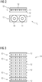
- Figure 2 illustrates the structure of an inductance 6 1 , ... 6 n as an example.
- the current limiting reactor 6 1 is composed of a pair of partial coils 10 and 11 which are arranged between two iron plates 12, the partial coils 10 and 11 being provided with taps or connection terminals, not shown in the figures.
- the two partial coils 10 and 11 form a partial coil pair 13.
- An inductance constructed in this way can be put together with other inductances in a particularly simple and compact manner to form a stack 14, with adjacent coil pairs 13 sharing a metal or iron plate 13 arranged between them.
- all of the metal plates 13 of the stack 14 have the same thickness. Only a metal plate is necessary between two pairs of coil sections 13 arranged one above the other.
- the metal plates are preferably designed to be identical to one another.
- the metal plates are preferably plates made of thin electrical steel sheets.
- the number of coil pairs required can be limited by means of an appropriate interconnection.
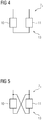
- two sub-coils 10 and 11 are connected in series as an example.
- Figure 5 shows the two partial coils 10 and 11 of a partial coil pair 13 connected in parallel. Since the partial coil pairs according to Figure 4 and Figure 5 otherwise not differentiate further, the partial coil pair 13 according to FIG Figure 5 only a quarter of the inductance of the partial coil pair according to Figure 4 on. If you designate partial coil pairs with full inductance with L1, see Figure 4 , and partial coil pairs according to Figure 5 that are connected in parallel with each other and thus have a quarter of the inductance of L1 with L2, 12 switching stages can be implemented with eight partial choke pairs, as can be seen from Table 1.
- n is the number of partial coil pairs with different inductances
- the number of possible switching stages results from 2 n -1.
- the partial coil pairs are graded in such a way that the following partial coil pair only has half the inductance. This means that with n partial coil pairs, 2 n -1 switching stages can be implemented with the same increments.
- the partial chokes 10 and 11 of a partial choke pair 13 are designed with only half the number of turns but with a doubling of the conductor cross-section compared to an adjacent partial choke pair, the size of the said partial choke pair remains approximately the same.
- the inductances of the partial choke pairs can now be quartered again, so that, according to this further development of the invention, four partial choke pairs with different inductances L1, L2, L4 and L8 result.
Priority Applications (1)
| Application Number | Priority Date | Filing Date | Title |
|---|---|---|---|
| EP19193135.1A EP3783630B1 (fr) | 2019-08-22 | 2019-08-22 | Dispositif de suppression d'une composante courant continu lors du fonctionnement d'un appareil électrique connecté à un réseau haute tension |
Applications Claiming Priority (1)
| Application Number | Priority Date | Filing Date | Title |
|---|---|---|---|
| EP19193135.1A EP3783630B1 (fr) | 2019-08-22 | 2019-08-22 | Dispositif de suppression d'une composante courant continu lors du fonctionnement d'un appareil électrique connecté à un réseau haute tension |
Publications (2)
| Publication Number | Publication Date |
|---|---|
| EP3783630A1 true EP3783630A1 (fr) | 2021-02-24 |
| EP3783630B1 EP3783630B1 (fr) | 2023-10-04 |
Family
ID=67734570
Family Applications (1)
| Application Number | Title | Priority Date | Filing Date |
|---|---|---|---|
| EP19193135.1A Active EP3783630B1 (fr) | 2019-08-22 | 2019-08-22 | Dispositif de suppression d'une composante courant continu lors du fonctionnement d'un appareil électrique connecté à un réseau haute tension |
Country Status (1)
| Country | Link |
|---|---|
| EP (1) | EP3783630B1 (fr) |
Cited By (1)
| Publication number | Priority date | Publication date | Assignee | Title |
|---|---|---|---|---|
| EP3786986B1 (fr) * | 2019-08-28 | 2023-10-04 | Siemens Energy Global GmbH & Co. KG | Circuit de réduction d'une part de flux continu dans le noyau magnétique mou d'un transformateur |
Citations (3)
| Publication number | Priority date | Publication date | Assignee | Title |
|---|---|---|---|---|
| DE2723767A1 (de) * | 1977-05-26 | 1978-11-30 | Messer Griesheim Gmbh | Wechselstromschweisstromquelle |
| WO2012041368A1 (fr) * | 2010-09-29 | 2012-04-05 | Siemens Transformers Austria Gmbh & Co Kg | Dispositif et procédé pour réduire une composante de flux magnétique continu dans le noyau d'un transformateur |
| EP3080821A1 (fr) | 2013-12-10 | 2016-10-19 | Siemens Aktiengesellschaft | Dispositif et procédé visant à réduire une composante de flux magnétique continu dans le noyau d'un transformateur |
-
2019
- 2019-08-22 EP EP19193135.1A patent/EP3783630B1/fr active Active
Patent Citations (3)
| Publication number | Priority date | Publication date | Assignee | Title |
|---|---|---|---|---|
| DE2723767A1 (de) * | 1977-05-26 | 1978-11-30 | Messer Griesheim Gmbh | Wechselstromschweisstromquelle |
| WO2012041368A1 (fr) * | 2010-09-29 | 2012-04-05 | Siemens Transformers Austria Gmbh & Co Kg | Dispositif et procédé pour réduire une composante de flux magnétique continu dans le noyau d'un transformateur |
| EP3080821A1 (fr) | 2013-12-10 | 2016-10-19 | Siemens Aktiengesellschaft | Dispositif et procédé visant à réduire une composante de flux magnétique continu dans le noyau d'un transformateur |
Cited By (1)
| Publication number | Priority date | Publication date | Assignee | Title |
|---|---|---|---|---|
| EP3786986B1 (fr) * | 2019-08-28 | 2023-10-04 | Siemens Energy Global GmbH & Co. KG | Circuit de réduction d'une part de flux continu dans le noyau magnétique mou d'un transformateur |
Also Published As
| Publication number | Publication date |
|---|---|
| EP3783630B1 (fr) | 2023-10-04 |
Similar Documents
| Publication | Publication Date | Title |
|---|---|---|
| DE2306917B2 (de) | Drosselspule oder Transformator | |
| EP3132515B1 (fr) | Onduleur pour délivrer de la puissance réactive et procédé de régulation de celui-ci | |
| EP2310919A1 (fr) | Circuit de simulation d'une charge électrique | |
| EP3080821B1 (fr) | Dispositif et procédé visant à réduire une composante de flux magnétique continu dans le noyau d'un transformateur | |
| EP0597409B1 (fr) | Véhicule multisystème | |
| DE102016201258A1 (de) | Elektrischer Spannungswandler mit mehreren Speicherdrosseln | |
| EP0682402B1 (fr) | Dispositif pour la limitation de la pente des grandeurs de sortie d'un convertisseur auto-commuté à circuit intermédiaire à tension continue | |
| EP3783630B1 (fr) | Dispositif de suppression d'une composante courant continu lors du fonctionnement d'un appareil électrique connecté à un réseau haute tension | |
| EP3167298B1 (fr) | Procédé de contrôle d'un élément semi-conducteur haute puissance | |
| DE2724920A1 (de) | Hochspannungsfeste signaluebertragungseinrichtung mit einem trennuebertrager | |
| DE4344709C2 (de) | Verfahren zur Umwandlung von unterschiedlich großen Gleich- oder Wechselspannungen in eine beliebig vorgegebene Spannung | |
| EP0682395B1 (fr) | Dispositif pour limitation de la vitesse de changement des courants et tensions entre conducteurs ou vers la terre et procédé l'utilisant | |
| EP2084940A1 (fr) | Dispositif de prébranchement à réactance | |
| WO2005124985A1 (fr) | Convertisseur matriciel pour le couplage de reseaux a tension triphasee | |
| EP3786987B1 (fr) | Dispositif de suppression d'une composante courant continu lors du fonctionnement d'un appareil électrique connecté à un réseau haute tension | |
| WO2018113926A1 (fr) | Convertisseur | |
| EP3571758B1 (fr) | Onduleur modulaire | |
| DE102015220220A1 (de) | Blindleistungskompensationseinrichtung sowie Verfahren zum Betreiben einer Blindleistungskompensationseinrichtung | |
| DE102018208626A1 (de) | Magnetisch regelbare Drossel zur Blindleistungskompensation mit kapazitiv beschalteten Zusatzwicklungen | |
| EP3402062B1 (fr) | Couplage d'au moins deux convertisseurs modulaires à niveaux multiples | |
| EP3160024B1 (fr) | Module bras d'un convertisseur modulair multi-niveaux avec un inductance commutable pour limitation des courants des fautes | |
| EP1592119A2 (fr) | Convertisseur électrique à découpage avec haute tension d'entrée | |
| WO2023072494A1 (fr) | Convertisseur et procédé pour amener un rapport de transformation réel en ligne avec un rapport de transformation cible | |
| AT288551B (de) | Schaltanordnung zur umschaltung der anzapfungen eines stelltransformators | |
| DE102022111459A1 (de) | Antriebssystem für ein Kraftfahrzeug und Kraftfahrzeug mit einem Antriebssystem |
Legal Events
| Date | Code | Title | Description |
|---|---|---|---|
| PUAI | Public reference made under article 153(3) epc to a published international application that has entered the european phase |
Free format text: ORIGINAL CODE: 0009012 |
|
| STAA | Information on the status of an ep patent application or granted ep patent |
Free format text: STATUS: THE APPLICATION HAS BEEN PUBLISHED |
|
| AK | Designated contracting states |
Kind code of ref document: A1 Designated state(s): AL AT BE BG CH CY CZ DE DK EE ES FI FR GB GR HR HU IE IS IT LI LT LU LV MC MK MT NL NO PL PT RO RS SE SI SK SM TR |
|
| AX | Request for extension of the european patent |
Extension state: BA ME |
|
| STAA | Information on the status of an ep patent application or granted ep patent |
Free format text: STATUS: REQUEST FOR EXAMINATION WAS MADE |
|
| 17P | Request for examination filed |
Effective date: 20210824 |
|
| RBV | Designated contracting states (corrected) |
Designated state(s): AL AT BE BG CH CY CZ DE DK EE ES FI FR GB GR HR HU IE IS IT LI LT LU LV MC MK MT NL NO PL PT RO RS SE SI SK SM TR |
|
| GRAP | Despatch of communication of intention to grant a patent |
Free format text: ORIGINAL CODE: EPIDOSNIGR1 |
|
| STAA | Information on the status of an ep patent application or granted ep patent |
Free format text: STATUS: GRANT OF PATENT IS INTENDED |
|
| INTG | Intention to grant announced |
Effective date: 20230329 |
|
| GRAS | Grant fee paid |
Free format text: ORIGINAL CODE: EPIDOSNIGR3 |
|
| GRAA | (expected) grant |
Free format text: ORIGINAL CODE: 0009210 |
|
| STAA | Information on the status of an ep patent application or granted ep patent |
Free format text: STATUS: THE PATENT HAS BEEN GRANTED |
|
| AK | Designated contracting states |
Kind code of ref document: B1 Designated state(s): AL AT BE BG CH CY CZ DE DK EE ES FI FR GB GR HR HU IE IS IT LI LT LU LV MC MK MT NL NO PL PT RO RS SE SI SK SM TR |
|
| REG | Reference to a national code |
Ref country code: GB Ref legal event code: FG4D Free format text: NOT ENGLISH |
|
| REG | Reference to a national code |
Ref country code: CH Ref legal event code: EP |
|
| REG | Reference to a national code |
Ref country code: IE Ref legal event code: FG4D Free format text: LANGUAGE OF EP DOCUMENT: GERMAN |
|
| REG | Reference to a national code |
Ref country code: DE Ref legal event code: R096 Ref document number: 502019009538 Country of ref document: DE |
|
| REG | Reference to a national code |
Ref country code: NL Ref legal event code: FP |
|
| REG | Reference to a national code |
Ref country code: LT Ref legal event code: MG9D |
|
| REG | Reference to a national code |
Ref country code: SE Ref legal event code: TRGR |
|
| PG25 | Lapsed in a contracting state [announced via postgrant information from national office to epo] |
Ref country code: GR Free format text: LAPSE BECAUSE OF FAILURE TO SUBMIT A TRANSLATION OF THE DESCRIPTION OR TO PAY THE FEE WITHIN THE PRESCRIBED TIME-LIMIT Effective date: 20240105 |
|
| PG25 | Lapsed in a contracting state [announced via postgrant information from national office to epo] |
Ref country code: IS Free format text: LAPSE BECAUSE OF FAILURE TO SUBMIT A TRANSLATION OF THE DESCRIPTION OR TO PAY THE FEE WITHIN THE PRESCRIBED TIME-LIMIT Effective date: 20240204 |
|
| PG25 | Lapsed in a contracting state [announced via postgrant information from national office to epo] |
Ref country code: LT Free format text: LAPSE BECAUSE OF FAILURE TO SUBMIT A TRANSLATION OF THE DESCRIPTION OR TO PAY THE FEE WITHIN THE PRESCRIBED TIME-LIMIT Effective date: 20231004 |
|
| PG25 | Lapsed in a contracting state [announced via postgrant information from national office to epo] |
Ref country code: ES Free format text: LAPSE BECAUSE OF FAILURE TO SUBMIT A TRANSLATION OF THE DESCRIPTION OR TO PAY THE FEE WITHIN THE PRESCRIBED TIME-LIMIT Effective date: 20231004 |
|
| PG25 | Lapsed in a contracting state [announced via postgrant information from national office to epo] |
Ref country code: LT Free format text: LAPSE BECAUSE OF FAILURE TO SUBMIT A TRANSLATION OF THE DESCRIPTION OR TO PAY THE FEE WITHIN THE PRESCRIBED TIME-LIMIT Effective date: 20231004 Ref country code: IS Free format text: LAPSE BECAUSE OF FAILURE TO SUBMIT A TRANSLATION OF THE DESCRIPTION OR TO PAY THE FEE WITHIN THE PRESCRIBED TIME-LIMIT Effective date: 20240204 Ref country code: GR Free format text: LAPSE BECAUSE OF FAILURE TO SUBMIT A TRANSLATION OF THE DESCRIPTION OR TO PAY THE FEE WITHIN THE PRESCRIBED TIME-LIMIT Effective date: 20240105 Ref country code: ES Free format text: LAPSE BECAUSE OF FAILURE TO SUBMIT A TRANSLATION OF THE DESCRIPTION OR TO PAY THE FEE WITHIN THE PRESCRIBED TIME-LIMIT Effective date: 20231004 Ref country code: BG Free format text: LAPSE BECAUSE OF FAILURE TO SUBMIT A TRANSLATION OF THE DESCRIPTION OR TO PAY THE FEE WITHIN THE PRESCRIBED TIME-LIMIT Effective date: 20240104 Ref country code: PT Free format text: LAPSE BECAUSE OF FAILURE TO SUBMIT A TRANSLATION OF THE DESCRIPTION OR TO PAY THE FEE WITHIN THE PRESCRIBED TIME-LIMIT Effective date: 20240205 |