EP3783629A1 - Coil and motor using same - Google Patents
Coil and motor using same Download PDFInfo
- Publication number
- EP3783629A1 EP3783629A1 EP19788724.3A EP19788724A EP3783629A1 EP 3783629 A1 EP3783629 A1 EP 3783629A1 EP 19788724 A EP19788724 A EP 19788724A EP 3783629 A1 EP3783629 A1 EP 3783629A1
- Authority
- EP
- European Patent Office
- Prior art keywords
- coil
- recesses
- conductive wire
- turns
- series
- Prior art date
- Legal status (The legal status is an assumption and is not a legal conclusion. Google has not performed a legal analysis and makes no representation as to the accuracy of the status listed.)
- Pending
Links
Images


Classifications
-
- H—ELECTRICITY
- H02—GENERATION; CONVERSION OR DISTRIBUTION OF ELECTRIC POWER
- H02K—DYNAMO-ELECTRIC MACHINES
- H02K1/00—Details of the magnetic circuit
- H02K1/06—Details of the magnetic circuit characterised by the shape, form or construction
- H02K1/12—Stationary parts of the magnetic circuit
- H02K1/14—Stator cores with salient poles
- H02K1/146—Stator cores with salient poles consisting of a generally annular yoke with salient poles
- H02K1/148—Sectional cores
-
- H—ELECTRICITY
- H01—ELECTRIC ELEMENTS
- H01F—MAGNETS; INDUCTANCES; TRANSFORMERS; SELECTION OF MATERIALS FOR THEIR MAGNETIC PROPERTIES
- H01F27/00—Details of transformers or inductances, in general
- H01F27/28—Coils; Windings; Conductive connections
- H01F27/2823—Wires
-
- H—ELECTRICITY
- H02—GENERATION; CONVERSION OR DISTRIBUTION OF ELECTRIC POWER
- H02K—DYNAMO-ELECTRIC MACHINES
- H02K1/00—Details of the magnetic circuit
- H02K1/06—Details of the magnetic circuit characterised by the shape, form or construction
- H02K1/12—Stationary parts of the magnetic circuit
- H02K1/14—Stator cores with salient poles
-
- H—ELECTRICITY
- H02—GENERATION; CONVERSION OR DISTRIBUTION OF ELECTRIC POWER
- H02K—DYNAMO-ELECTRIC MACHINES
- H02K3/00—Details of windings
- H02K3/04—Windings characterised by the conductor shape, form or construction, e.g. with bar conductors
-
- H—ELECTRICITY
- H02—GENERATION; CONVERSION OR DISTRIBUTION OF ELECTRIC POWER
- H02K—DYNAMO-ELECTRIC MACHINES
- H02K3/00—Details of windings
- H02K3/04—Windings characterised by the conductor shape, form or construction, e.g. with bar conductors
- H02K3/18—Windings for salient poles
-
- H—ELECTRICITY
- H02—GENERATION; CONVERSION OR DISTRIBUTION OF ELECTRIC POWER
- H02K—DYNAMO-ELECTRIC MACHINES
- H02K3/00—Details of windings
- H02K3/46—Fastening of windings on the stator or rotor structure
-
- H—ELECTRICITY
- H02—GENERATION; CONVERSION OR DISTRIBUTION OF ELECTRIC POWER
- H02K—DYNAMO-ELECTRIC MACHINES
- H02K1/00—Details of the magnetic circuit
- H02K1/06—Details of the magnetic circuit characterised by the shape, form or construction
- H02K1/22—Rotating parts of the magnetic circuit
- H02K1/32—Rotating parts of the magnetic circuit with channels or ducts for flow of cooling medium
-
- H—ELECTRICITY
- H02—GENERATION; CONVERSION OR DISTRIBUTION OF ELECTRIC POWER
- H02K—DYNAMO-ELECTRIC MACHINES
- H02K15/00—Methods or apparatus specially adapted for manufacturing, assembling, maintaining or repairing of dynamo-electric machines
- H02K15/04—Methods or apparatus specially adapted for manufacturing, assembling, maintaining or repairing of dynamo-electric machines of windings, prior to mounting into machines
- H02K15/0435—Wound windings
- H02K15/0442—Loop windings
- H02K15/045—Form wound coils
-
- H—ELECTRICITY
- H02—GENERATION; CONVERSION OR DISTRIBUTION OF ELECTRIC POWER
- H02K—DYNAMO-ELECTRIC MACHINES
- H02K2203/00—Specific aspects not provided for in the other groups of this subclass relating to the windings
- H02K2203/09—Machines characterised by wiring elements other than wires, e.g. bus rings, for connecting the winding terminations
-
- H—ELECTRICITY
- H02—GENERATION; CONVERSION OR DISTRIBUTION OF ELECTRIC POWER
- H02K—DYNAMO-ELECTRIC MACHINES
- H02K3/00—Details of windings
- H02K3/32—Windings characterised by the shape, form or construction of the insulation
Abstract
Description
- The present disclosure relates to a coil of a wound conductive wire having a rectangular cross section, and a motor using the coils.
- Industry motors and on-vehicle motors have been highly demanded in recent years. In particular, a low cost but highly efficient motor has been demanded.
- In one of methods of improving efficiency of a motor, coils respectively disposed in slots on a stator can reduce a loss due to eddy currents. With this configuration, it is possible to suppress a loss due to a current flowing into the coils while the motor is driven.
- As a method of reducing an eddy current in a coil, such a conductive wire has been proposed that a cross section of aggregate conductive wires is separated into a plurality of regions (for example, see PTL 1).
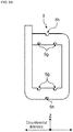
- The coil is spirally wound, in each of slots, around each of teeth provided on a stator. Strength of a magnetic field generated in a coil often changes each time an external current is supplied or a current is supplied externally. Along with this, such eddy currents as indicated by arrows A in
FIG. 10 are induced in the coil.FIG. 10 is an explanatory diagram of eddy currents A generated inconventional coil 5. Depending on a size of a coil, resistivity of a material of the coil, or operating conditions for the coil, the coil generates more heat. A significant loss due to the generated heat would be problematic, such as lowered efficiency of a motor. - PTL 1: Japanese Patent No.
5309595 - The present disclosure has been made in view of such issues as described above. An object of the present disclosure is to achieve a coil capable of reducing an eddy current induced in a field magnet as an armature coil is energized, and of reducing a power loss due to an eddy current loss, as well as to achieve a motor using the coils.
- To achieve the object described above, a coil according to the present disclosure is a coil of a conductive wire that has a quadrangular cross section, that is spirally wound and laminated to have a series of turns including first to n-th turns (n is an integer of 3 or more), and that is provided, on at least some of the first to n-th turns in the coil, with deformed portions representing recesses each having a shape different from a shape of another portion of the conductive wire. In each of the first and n-th turns respectively lying at both ends of the series of turns, an outer surface lying on a side opposite to a center of the series of turns extends flush along with a plane intersecting the series of turns.
- In an ordinary coil, a loop of an eddy current is generated in each of straight portions of a conductive wire forming the coil, in each of axial directions or circumferential directions, in each of teeth. As this loop becomes greater in size, an eddy current loss increases. However, recesses on a conductive wire portion of the coil according to the present disclosure offer such effects that a loop of an eddy current generated in the conductive wire is reduced in size to reduce an eddy current loss.
- The recesses provided, in each of the teeth, on the conductive wire extending longer in a Z-axis direction serving as a rotation axis of the motor are provided in both of the circumferential directions. The recesses on the conductive wire on a top side of the coil or a bottom side of the coil are provided in the Z-axis direction serving as the rotation axis of the motor. According to the configurations described above, it is possible to reduce an eddy current to be generated along each of coil axes. Furthermore, to provide a plurality of the recesses on portions, extending along one axis, of the conductive wire, providing the recesses alternately on each of straight portions of the conductive wire preferably shortens in length a loop of an eddy current to be generated in the conductive wire. Furthermore, since an eddy current would be more likely to be generated on a side adjacent to each of the teeth, i.e., on a side adjacent to a center of spiral rotation of the coil, it is preferable that more recesses be provided on an inside of the spirally formed coil. Furthermore, in a spirally formed coil structure, it can be expected that providing more recesses on a side adjacent to a rotation axis center of the motor achieve effects of efficiently reducing an eddy current.
- The recesses being provided divide an eddy current generated in each of straight components of the conductive wire, leading to effects of reducing the eddy current. Therefore, it can be expected that providing more recesses achieve effects of reducing an eddy current loss. However, cutting out a conventional conductive wire would cause some portions of the conductive wire to have smaller cross-sectional areas with respect to a flow direction of a current. Therefore, resistance in the conductive wire increases, leading to greater Joule heat. Therefore, to provide the recesses, it is preferable to provide the recesses in a balanced manner between effects of reducing an eddy current and Joule heat due to an increase in resistance of the conductive wire.
- A motor according to the present disclosure includes a stator including a stator core, teeth respectively protruding from the stator core, and the coils according to the present disclosure, which are respectively wound around the teeth.
- As the configuration further reduces an eddy current loss in the coils, it is possible to suppress heat generation due to the eddy current loss, to reduce a loss in the coils, and to increase efficiency of the motor.
- According to the present disclosure, an eddy current loss in the coils can be further reduced. A highly efficient motor can also be achieved.
-
-
FIG. 1A is a top view illustrating a motor according to an exemplary embodiment. -
FIG. 1B is a side view illustrating the motor according to the exemplary embodiment. -
FIG. 1C is a cross-sectional view taken alongline 1C-1C inFIG. 1B . -
FIG. 2 is a perspective view illustrating a coil according to the exemplary embodiment. -
FIG. 3 is a side view illustrating the coil according to the exemplary embodiment. -
FIG. 4 is a perspective view illustrating a coil, for purpose of comparison with the exemplary embodiment. -
FIG. 5 is a side view illustrating the coil, for purpose of comparison with the exemplary embodiment. -
FIG. 6 is an explanatory diagram of eddy currents generated in the coil according to the exemplary embodiment. -
FIG. 7A is a front view illustrating the coil according to the exemplary embodiment. -
FIG. 7B is a front view illustrating a coil according to Modification Example 1. -
FIG. 7C is a front view illustrating another coil according to Modification Example 1. -
FIG. 8A is a front view illustrating the coil according to the exemplary embodiment. -
FIG. 8B is a front view illustrating a coil according to Modification example 2. -
FIG. 8C is a front view illustrating another coil according to Modification example 2. -
FIG. 9A is a cross-sectional view illustrating the coil according to the exemplary embodiment. -
FIG. 9B is a cross-sectional view illustrating a coil according to Modification example 3. -
FIG. 10 is an explanatory diagram of eddy currents generated in a conventional coil. - An exemplary embodiment will be described herein in detail with reference to the accompanying drawings. The preferable exemplary embodiment described below is essentially a mere example, and does not intend to limit the present invention, applications, and purposes.
-
FIG. 1A is a topview illustrating motor 1 according to the exemplary embodiment.FIG. 1B is a sideview illustrating motor 1 according to the exemplary embodiment.FIG. 1C is a cross-sectional view taken alongline 1C-1C inFIG. 1B . However, the views do not illustrate a cover case, for example. Inside of the cover case (not illustrated),motor 1 includesshaft 2,rotor 3,stator 4, coils U11, U22, U32, U41, V12, V21, V31, V42, W11, W22, W32, and W41, andbus bars 51 to 54. - In here, a longer direction (a direction vertical to a paper plane of
FIG. 1A ) ofshaft 2 may sometimes be referred to as a Z-axis direction. Directions orthogonal to the Z-axis direction (directions parallel to the paper plane ofFIG. 1A ) may sometimes be respectively referred to as an X-axis direction and a Y-axis direction. The X-axis direction and the Y-axis direction are orthogonal to each other. - A term "integrated" or "integrally" denotes a state of an object where not only a plurality of constituent parts are mechanically coupled with each other with bolts or through caulking, for example, but also a plurality of constituent parts are electrically coupled with each other through material coupling such as covalent coupling, ion coupling, or metal coupling, for example, or a plurality of constituent parts are electrically coupled with each other through material coupling after all of the constituent parts are melted.
-
Shaft 2 internally includeshollow portion 2a extending in the Z-axis direction. A plurality of throughholes 2b are provided on a side surface ofshaft 2.Hollow portion 2a serves as a passage for refrigerant C used to cool inside ofmotor 1. Refrigerant C flows inside ofhollow portion 2a in the Z-axis direction to circulate and flow inside ofmotor 1. Some of refrigerant C flowing inside ofhollow portion 2a flows from the plurality of throughholes 2b outward from around a center ofmotor 1, i.e., flows fromrotor 3 towardstator 4, to coolrotor 3 andstator 4. -
Rotor 3 is provided to abut an outer circumference ofshaft 2.Rotor 3 includesmagnets 31 each facingstator 4.Magnets 31 respectively have N-poles and S-poles alternately disposed in an outer circumferential direction ofshaft 2. In the present exemplary embodiment, neodymium magnets are used asmagnets 31 used inrotor 3. However, its material, shape, and composition can be appropriately changed in accordance with an output of a motor, for example. -
Stator 4 includesstator core 41 having a substantially annular shape, a plurality ofteeth 42 provided on its inner circumference at equal intervals, andslots 43 respectively provided betweenteeth 42. When viewed in the Z-axis direction,stator 4 is disposed outside ofrotor 3 to be away fromrotor 3 at a certain gap. -
Stator core 41 is die-cut and formed from electromagnetic steel sheets containing silicon, for example, and laminated to each other, for example. - In the present exemplary embodiment,
rotor 3 includes a total of ten magnetic poles, including five N-poles and five S-poles facing stator 4. Anumber ofslots 43 is 12. However, the present invention is not particularly limited to the numbers described above. A combination of another number of magnetic poles and another number of slots is also applicable. -
Stator 4 includes 12 coils U11, U22, U32, U41, V12, V21, V31, V42, W11, W22, W32, and W41. The coils are attached topredetermined teeth 42, and are disposed inpredetermined slots 43 when viewed in the Z-axis direction. That is, coils U11, U22, U32, U41, V12, V21, V31, V42, W11, W22, W32, and W41 are respectively wound in a concentrated manner with respect toteeth 42. Furthermore, coils U11, U22, U32, and U41 are integrally disposed tobus bar 51, coils V12, V21, V31, and V42 are integrally disposed tobus bar 52, and coils W11, W22, W32, and W41 are integrally disposed tobus bar 53. - In each of symbols UXY, VXY, and WXY representing the coils, a first letter represents one of phases of motor 1 (one of U-phase, V-phase, and W-phase in the present exemplary embodiment). A second letter represents an order of arrangement of a corresponding one of the coils in the one of the phases. A third letter represents a winding direction of each of the coils. In the present exemplary embodiment, 1 represents a clockwise direction, whereas 2 represents a counterclockwise direction. Therefore, coil U11 represents a first coil in an order of arrangement in the U-phase, and a direction of winding is the clockwise direction. Coil V42 represents a fourth coil in an order of arrangement in the V-phase, and a direction of winding is the counterclockwise direction. A term "clockwise" denotes right-handed rotation when viewed from the center of
motor 1. A term "counterclockwise" denotes left-handed rotation when viewed from the center ofmotor 1. - Specifically, coils U11, U41 are U-phase coils, whereas coils U22, U32 are U-bar-phase (a direction of a magnetic field is opposite to a direction of a magnetic field generated from a U-phase coil) coils. However, the coils will be collectively referred to as U-phase coils unless otherwise specified. Similarly, coils V12, V21, V31, and V42 and coils W11, W22, W32, and W41 will be respectively collectively referred to as V-phase coils and W-phase coils.
-
FIG. 2 is a perspectiveview illustrating coil 5 according to the exemplary embodiment.FIG. 3 is a sideview illustrating coil 5 according to the present exemplary embodiment.FIG. 4 is a perspectiveview illustrating coil 5, for purpose of comparison with the exemplary embodiment.FIG. 5 is a sideview illustrating coil 5, for purpose of comparison with the exemplary embodiment.FIGS. 3 and5 are the side views ofcoil 5 when viewed from a side in circumferential directions. Furthermore,coil 5 according to the present exemplary embodiment illustrated inFIGS. 2 and3 includes coils U11, U22, U32, U41, V12, V21, V31, V42, W11, W22, W32, and W41 attached toteeth 42 ofmotor 1 illustrated inFIG. 1C . -
Coil 5 includesconductive wire 5a being wound,insulation film 5b provided on a surface ofconductive wire 5a, andextended portions coil 5. A second turn to the tenth turn ofcoil 5 are wound in a rectangular shape in a plan view and each have four coil sides. -
Conductive wire 5a is a wire material made of a conductive member having a rectangular cross section.Conductive wire 5a is spirally wound ten turns and laminated in upper and lower directions in a single layer to form a series of turns.Conductive wire 5a is made of, for example, copper, aluminum, zinc, magnesium, brass, iron, steel use stainless (SUS), for example. - Hereinafter, a portion where the conductive wire is wound from a tip of
extended portion 5c to a position below a position whereextended portion 5d is provided is referred to as the first turn. Subsequent portions, each of which the conductive wire is wound one turn, are counted as the second turn to the tenth turn. A desired starting point can be specified for each turn. A side where the first turn ofcoil 5 is provided may be referred to as "outside", whereas a side where the tenth turn is provided may be referred to as "inside". One reason for this is that outside of the motor is referred to as "outside", whereas a side of the center of the motor is referred to as "inside", with respect to a radial direction of a motor structure. -
Insulation film 5b is provided wholly on the surface ofconductive wire 5a to insulatecoil 5 from an external member (not illustrated). Inmotor 1 illustrated inFIGS. 1A to 1C , for example, coils 5 are each insulated fromstator core 41 andteeth 42 byinsulation film 5b and an insulation member (not illustrated) such as insulation paper. Furthermore, the turns adjacent to each other incoil 5 are insulated byinsulation film 5b.Insulation film 5b is made of, for example, polyimide, nylon, polyether ether ketone (PEEK), acrylic, amide imide, ester imide, enamel, or heat resistant resin, for example. A thickness ofinsulation film 5b is approximately several ten pm ranging, for example, from 10 pm to 50 pm inclusive. -
Extended portions conductive wire 5a.Extended portions coil 5, in other words, from planes intersecting the series of turns ofconductive wire 5a to receive an externally supplied current or to supply a current externally. Onextended portions insulation film 5b is removed to respectively couple with external members such as any ofbus bars 51 to 54 illustrated inFIGS. 1A to 1C . It is not necessary thatinsulation film 5b be removed from whole areas ofextended portions insulation film 5b may be removed from at least portions necessary for coupling withbus bars 51 to 54. - Differences in shape between the coil, for purpose of comparison, and the coil according to the present exemplary embodiment will herein be described with reference to the accompanying drawings.
- In
coil 5 illustrated inFIGS. 4 and5 , for purpose of comparison, eddy currents as illustrated inFIG. 10 are generated in each of straightforward portions of the turns of the conductive wire. The generated eddy currents lead to Joule heat causing a temperature of the motor to rise to lower efficiency of the motor. - In
coil 5 according to the present exemplary embodiment, as illustrated inFIGS. 2 and3 , on the other hand, recesses 5e and 5f are provided in the circumferential directions, in each ofteeth 42, on each of portions, which extend along axial directions of the turns, of the conductive wire. A size of each ofrecesses Recesses Recesses FIGS. 2 and3 to allow loops of eddy currents to become further smaller. The size of each ofrecesses -
FIG. 6 is an explanatory diagram of eddy currents generated in the coil according to the exemplary embodiment. In the conductive wire provided withrecesses FIGS. 2 and3 , the eddy currents illustrated by arrows A inFIG. 6 are induced. The eddy currents illustrated inFIG. 6 are respectively smaller than eddy currents to be generated in a conventional coil. - A shape of each of
recesses FIGS. 2 and3 is a quadrangle. However, the shape may be, but not limited to, a triangle, a trapezoid, a circle, an inverted triangle, or an inverted trapezoid, for example. Furthermore, the shape may be an R-chamfered or C-chamfered polygonal shape, since a shape of each of corner portions greatly affects coil machining accuracy. -
Recesses FIGS. 2 and3 are provided, in each of the teeth, on portions, which extend along the axial directions of the turns, of the conductive wire. However,recesses - A number of the recesses being provided represents a natural number of 1 or greater. For example, to provide only one recess on a side, providing the recess on an inside of a coil offers higher effects of reducing an eddy current loss.
- To provide an even number of recesses, i.e., to provide two or more recesses, alternately providing the recesses on sides identically in number in the circumferential directions of a coil offers higher effects of reducing an eddy current loss. One reason for this is that, if recesses are unevenly provided in number in the circumferential directions of a coil, a longer loop of an eddy current is generated on a side, where no recess is provided, of the coil, leading to less effects of reducing an eddy current loss.
- To provide an odd number of recesses, i.e., to provide three or more recesses, providing more recesses on an inside, where each of teeth is present, of a coil, offers higher effects of reducing an eddy current loss. One reason for this is identical to the reason of a case where one recess is provided.
- As described above,
coil 5 according to the present exemplary embodiment iscoil 5 ofconductive wire 5a that has a quadrangular cross section, that is spirally wound and laminated to have a series of turns including first to n-th turns (n is an integer of 3 or more), and that is provided, on at least some of the first to n-th turns incoil 5, with deformed portions representing recesses each having a shape different from a shape of another portion ofconductive wire 5a. In each of the first and n-th turns respectively lying at both ends of the series of turns, an outer surface lying on a side opposite to a center of the series of turns extends flush along with a plane intersecting the series of turns. - With this configuration, where an eddy current loss in
coil 5 is further reduced, it is possible to suppress heat generation due to the eddy current loss, to reduce a loss incoil 5, and to increase efficiency ofmotor 1. - In the present exemplary embodiment, the number of turns in
coil 5 has been specified to 10. However, the number of turns is not particularly limited to this number. Another number may be applied. That is, in a coil of a conductive wire that has a quadrangular cross section, and that is spirally wound and laminated in the radial directions to have a series of turns including first to n-th turns (n is an integer of 3 or more), recesses may not be provided on all of n turns, but may be provided on at least some of a plurality of turns. When recesses are provided, there are concerns of a decrease in cross-sectional area of a coil, an increase in coil conductivity, and an increase in Joule heat. Therefore, providing more recesses on an inside in the radial directions, which would be greatly affected by an eddy current loss, of a conductive wire, is more effective. Even when recesses are to be provided on some of such turns, it is preferable that the recesses be provided in consideration of balance between a reduction in rigidity of a coil and an increase in Joule heat due to an increase in resistance in a conductive wire. - Furthermore, the deformed portions may be provided at least on the nth turn.
- Furthermore, the deformed portions may be provided, on the conductive wire, in the Z-axis direction representing a direction perpendicular to the radial directions and the circumferential directions of the coil, with recesses that are cut out in the circumferential directions of the conductive wire.
- Furthermore,
motor 1 according to the present exemplary embodiment includesrotor 3, andstator 4 includingstator core 41,teeth 42 protruding fromstator core 41, and coils 5 according to the exemplary embodiment, which are respectively wound aroundteeth 42. -
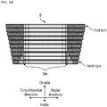
FIG. 7A is a frontview illustrating coil 5 according to the exemplary embodiment.FIG. 7A is the front view ofcoil 5 illustrated inFIGS. 2 and3 when viewed from the inside to the outside in the radial directions of the coil.FIGS. 7B and7C are front views ofcoil 5 according to Modification Example 1 when viewed from the inside to the outside in the radial directions of the coil, for purpose of comparison.FIG. 7B is the frontview illustrating coil 5 according to Modification Example 1.FIG. 7C is the front view illustrating anothercoil 5 according to Modification Example 1. For convenience of description, inFIG. 7A , only an n-th turn of the conductive wire wound n turns, i.e., an innermost turn in the radial directions of the coil, is illustrated. The conductive wire in other turns than the n-th turn andextended portion 5c are omitted.FIGS. 7B and7C illustrate only one axial portion of the conductive wire, which is provided with recesses that are cut out. The conductive wire in other turns than the n-th turn andextended portions -
Coil 5 illustrated inFIGS. 7A ,7B , and7C is provided withrecesses 5e respectively representing cut-out portions (deformed portions) provided on the inside of the coil in each of the teeth, andrecesses 5f respectively representing cut-out portions (deformed portions) provided on the outside of the coil in each of the teeth. - A shape of each of the recesses in
FIG. 7A is substantially rectangular. The shape of each of the recesses may be substantially triangular, as illustrated inFIG. 7B , substantially semicircular, as illustrated inFIG. 7C , or trapezoid. The recesses are cut out in the circumferential directions of the coil. - There are a plurality of the recesses in
FIGS. 7A to 7C . In that case, it is preferable that the recesses are provided in both of the circumferential directions of the coil. It is preferable that a number ofrecesses 5e provided on the inside in the radial directions of the coil be equal to or greater by one than a number ofrecesses 5f provided on the outside of the conductive wire. To provide such a recess as illustrated inFIGS. 7A to 7C one and only, it is preferable thatrecess 5e be provided on the inside of the spirally formed conductive wire. - To provide in plural such recesses as illustrated in
FIGS. 7A to 7C , it is preferable thatrecesses 5e provided on the inside of the conductive wire andrecesses 5f provided on the outside of the conductive wire be provided in both of the circumferential directions of the coil, but be not provided at positions identical to each other in the Z-axis direction. - As described above, it is preferable that recesses on the inside of
coil 5 be equal to or greater in number than recesses on the outside ofcoil 5. - Furthermore, in the deformed portions, it is preferable that recesses on the inside of the conductive wire and the recesses on the outside of the conductive wire be not provided at positions identical to each other in the Z-axis direction.
- In Modification Example 1, the number of turns of
coil 5 has been specified to 10. However, the number of turns is not particularly limited to this number. Another number may be applied. -
FIG. 8A is a front view illustrating the coil according to the exemplary embodiment.FIG. 8A is the front view ofcoil 5 illustrated inFIGS. 2 and3 when viewed from the inside to the outside in the radial directions of the coil.FIGS. 8B and8C are front views ofcoil 5 according to Modification Example 2 when viewed from the inside to the outside in the radial directions of the coil, for purpose of comparison.FIG. 8B is the front view illustrating the coil according to Modification Example 2.FIG. 8C is the front view illustrating another coil according to Modification Example 2. For convenience of description, inFIGS. 8A ,8B , and8C , only an n-th turn of the conductive wire wound n turns, i.e., an innermost turn, is illustrated. The conductive wire in other turns than the n-th turn andextended portion 5c are omitted. - The recesses that are cut out on
coil 5 illustrated inFIGS. 8A ,2 and3 are arranged only in the Z-axis direction of the conductive wire. InFIGS. 8B and8C illustrating the present modification example, the recesses are provided on a top portion of the coil and a bottom portion of the coil. In this case, the recesses that are cut out on the inside of the coil are illustrated as 5g, whereas the recesses that are cut out on the outside of the coil are illustrated as 5h. - That is,
coil 5 illustrated inFIGS. 8B and8C is provided withrecesses 5g respectively representing cut-out portions (deformed portions) on the inside of the coil at the top and bottom portions of each of the teeth andrecesses 5h respectively representing cutout portions (deformed portions) on the outside of the coil at the top and bottom portions of each of the teeth. -
Recesses 5e, recesses 5f, recesses 5g, andrecesses 5h may all be provided, or may be partially provided on any of sides.FIG. 8C illustrates an example in which recesses 5e, recesses 5f, recesses 5g, andrecesses 5h are provided on all the sides.Recesses 5e, recesses 5f, recesses 5g, andrecesses 5h are not limited in position. - In the present modification example, the number of the recesses has been specified to 5 or 3 on each of the sides. However, the number of the recesses is not particularly limited to this number. Another number may be applied.
-
FIG. 9A is a cross-sectionalview illustrating coil 5 according to the exemplary embodiment.FIG. 9A illustrates a cross section ofcoil 5 taken alongline 1C-1C illustrated inFIG. 1B , as well as illustrates a cross section taken alongline 1C-1C illustrated inFIG. 3 and viewed in the Z-axis direction.FIG. 9B has been illustrated for purpose of comparison withcoil 5 according to the present modification example.FIG. 9B is a cross-sectionalview illustrating coil 5 according to Modification Example 3. Note that, for convenience of description, inFIGS. 9A and9B , illustration of tooth portions in the coil is omitted. -
Recesses 5e illustrated inFIG. 9A are provided on eighth to tenth turns. Degrees of cut out of the recesses are all identical to each other in size. InFIG. 9B illustrating the present modification example, degrees of cut out ofrecesses 5e on the conductive wire are not identical to each other. A degree of cut out on the conductive wire increases toward inside in the radial directions. Since an eddy current generated on the inside in the radial directions of the coil tends to be greater than an eddy current generated on the outside in the radial directions of the coil, howmuch recesses 5e are cut put has been made different in size. Furthermore, as illustrated inFIG. 6 , from the eighth turn to the tenth turn, the conductive wire, at locations whererecesses 5e are not cut out, is narrowed in width size in the circumferential directions to formgaps 5j between the teeth. - As described above, it is preferable that, in the deformed portions, a degree of cut out on the conductive wire increases toward inside in the radial directions of
coil 5. - As illustrated in
FIGS. 9A and9B ,recesses 5e have been provided only on the three turns, i.e., the eighth to tenth turns, on the inside in the radial directions ofcoil 5. However, the number of turns is not particularly limited to this number. Another number may be applied. In the present modification example, the number of the turns ofcoil 5 has been specified to 10. However, the number of turns is not particularly limited to this number. Another number may be applied. -
Coil 5 can be formed through casting. With this method, a conductive wire having a large cross-sectional area can be easily formed into a spirally wound coil. However, a coil may be formed through another method, instead of casting. For example, a coil may be cut from a solid object of a material such as copper, aluminum, zinc, magnesium, iron, SUS, or brass. Furthermore, for example, a coil may be formed from an integrated member where individually molded components are welded or joined with each other. - The coil according to the present disclosure can reduce generation of eddy currents, and is useful when applied to a motor or a power device, for example.
-
- 1 motor
- 2 shaft
- 2a hollow portion
- 2b through hole
- 3 rotor
- 4 stator
- 5 coil
- 5a conductive wire
- 5b insulation film
- 5c extended portion
- 5d extended portion
- 5e recess
- 5f recess
- 5g recess
- 5h recess
- 5j gap
- 31 magnet
- 41 stator core
- 42 tooth
- 43 slot
- 51 bus bar
- 52 bus bar
- 53 bus bar
- 54 bus bar
- U11, U22, U32, U41, V12, V21, V31, V42, W11, W22, W32, W41 coil
Claims (10)
- A coil of a conductive wire having a quadrangular cross section, the conductive wire being spirally wound and laminated to have a series of turns including first to n-th turns, where n is an integer of 3 or more, the conductive wire being provided, on at least some of the first to n-th turns in the coil, with deformed portions representing recesses each having a shape different from a shape of another portion of the conductive wire, where, in each of the first and n-th turns respectively lying at both ends of the series of turns, an outer surface lying on a side opposite to a center of the series of turns extends flush along with a plane intersecting the series of turns.
- The coil according to claim 1, wherein the deformed portions are at least provided on the n-th turn.
- The coil according to claim 1, wherein the deformed portions are provided, on the conductive wire, in a Z-axis direction representing a direction perpendicular to radial directions and circumferential directions of the coil, with the recesses that are cut out in the circumferential directions of the conductive wire.
- The coil according to claim 1, wherein the deformed portions include the recesses that are cut out, and that are provided on a top side of the coil or a bottom side of the coil.
- The coil according to claim 3, wherein a number of the recesses on an inside of the coil is equal to or greater than a number of the recesses on an outside of the coil.
- The coil according to claim 4, wherein a number of the recesses on an inside of the coil is equal to or greater than a number of the recesses on an outside of the coil.
- The coil according to claim 3, wherein, on the deformed portions, the recesses on an inside of the conductive wire and the recesses on an outside of the conductive wire are not provided at positions identical to each other in the Z-axis direction.
- The coil according to claim 4, wherein, on the deformed portions, the recesses on an inside of the conductive wire and the recesses on an outside of the conductive wire are not provided at positions identical to each other in a Z-axis direction.
- The coil according to claim 2, wherein, on the deformed portions, a degree of cut out on the conductive wire increases toward inside in the radial directions of the coil.
- A motor comprising:a rotor; anda stator includinga stator core,teeth protruding from the stator core, andthe plurality of the coils according to claim 1, the plurality of the coils being respectively wound around the teeth.
Applications Claiming Priority (2)
| Application Number | Priority Date | Filing Date | Title |
|---|---|---|---|
| JP2018079731 | 2018-04-18 | ||
| PCT/JP2019/015538 WO2019203076A1 (en) | 2018-04-18 | 2019-04-10 | Coil and motor using same |
Publications (2)
| Publication Number | Publication Date |
|---|---|
| EP3783629A1 true EP3783629A1 (en) | 2021-02-24 |
| EP3783629A4 EP3783629A4 (en) | 2021-05-26 |
Family
ID=68239510
Family Applications (1)
| Application Number | Title | Priority Date | Filing Date |
|---|---|---|---|
| EP19788724.3A Pending EP3783629A4 (en) | 2018-04-18 | 2019-04-10 | Coil and motor using same |
Country Status (5)
| Country | Link |
|---|---|
| US (1) | US11411452B2 (en) |
| EP (1) | EP3783629A4 (en) |
| JP (1) | JP7257602B2 (en) |
| CN (1) | CN111971763A (en) |
| WO (1) | WO2019203076A1 (en) |
Cited By (2)
| Publication number | Priority date | Publication date | Assignee | Title |
|---|---|---|---|---|
| EP3958442A3 (en) * | 2020-08-19 | 2022-03-02 | Honeywell International Inc. | Electric machine stator winding |
| EP4160878A4 (en) * | 2020-05-29 | 2023-12-06 | Panasonic Intellectual Property Management Co., Ltd. | Coil, stator comprising same, and motor |
Families Citing this family (3)
| Publication number | Priority date | Publication date | Assignee | Title |
|---|---|---|---|---|
| JP7257602B2 (en) * | 2018-04-18 | 2023-04-14 | パナソニックIpマネジメント株式会社 | coil |
| WO2021117320A1 (en) * | 2019-12-12 | 2021-06-17 | パナソニックIpマネジメント株式会社 | Coil and motor comprising same |
| US11894756B2 (en) * | 2021-01-25 | 2024-02-06 | Honeywell International Inc. | Systems and methods for electric propulsion systems for electric engines |
Family Cites Families (20)
| Publication number | Priority date | Publication date | Assignee | Title |
|---|---|---|---|---|
| CH579354A5 (en) | 1973-10-26 | 1976-09-15 | Nestle Sa | |
| JPS56164654U (en) * | 1980-05-07 | 1981-12-07 | ||
| JPS56164656U (en) * | 1980-05-07 | 1981-12-07 | ||
| JPS56164654A (en) * | 1980-05-23 | 1981-12-17 | Tech Res & Dev Inst Of Japan Def Agency | Data transmitting and receiving device |
| CN2289288Y (en) * | 1997-01-30 | 1998-08-26 | 华中理工大学 | Foil hollow reactor |
| JPH1198744A (en) * | 1997-09-19 | 1999-04-09 | Toshiba Corp | Rotor of rotary electric machine |
| JP4581188B2 (en) * | 2000-06-13 | 2010-11-17 | 日産自動車株式会社 | Flat wire structure and flat wire winding method |
| JP3618079B2 (en) * | 2000-07-11 | 2005-02-09 | 株式会社モステック | Multi-line trapezoidal coil, and method and apparatus for manufacturing the coil |
| JP4691275B2 (en) * | 2001-06-28 | 2011-06-01 | 澤藤電機株式会社 | Winding structure of starter |
| JP2003153509A (en) * | 2001-11-08 | 2003-05-23 | Matsushita Electric Ind Co Ltd | Motor |
| DE102004044986A1 (en) * | 2004-09-16 | 2006-04-06 | Siemens Ag | Permanent magnet synchronous machine with flat wire windings |
| JP5309595B2 (en) | 2008-02-19 | 2013-10-09 | 住友電気工業株式会社 | Motor, reactor using conductive wire as coil, and method for manufacturing said conductive wire |
| JP5434227B2 (en) * | 2009-04-20 | 2014-03-05 | トヨタ自動車株式会社 | Stator and stator manufacturing method |
| JP2011234443A (en) * | 2010-04-26 | 2011-11-17 | Aisin Seiki Co Ltd | Coil and armature |
| DE102012212637A1 (en) | 2012-07-18 | 2014-01-23 | Fraunhofer-Gesellschaft zur Förderung der angewandten Forschung e.V. | Casting electrical coil |
| JP6379689B2 (en) * | 2014-06-03 | 2018-08-29 | 株式会社デンソー | COIL DEVICE AND COIL DEVICE MANUFACTURING METHOD |
| CN206758245U (en) * | 2017-06-15 | 2017-12-15 | 深圳市信维通信股份有限公司 | A kind of induction coil structure for wireless charging device |
| JP7257602B2 (en) * | 2018-04-18 | 2023-04-14 | パナソニックIpマネジメント株式会社 | coil |
| JP2020137371A (en) * | 2019-02-25 | 2020-08-31 | 株式会社デンソー | Armature and rotary electric machine |
| US20200328011A1 (en) * | 2019-04-12 | 2020-10-15 | Goto Denshi Co., Ltd. | Electric wire for high frequency, high voltage and large current |
-
2019
- 2019-04-10 JP JP2020514098A patent/JP7257602B2/en active Active
- 2019-04-10 EP EP19788724.3A patent/EP3783629A4/en active Pending
- 2019-04-10 CN CN201980025986.9A patent/CN111971763A/en active Pending
- 2019-04-10 WO PCT/JP2019/015538 patent/WO2019203076A1/en unknown
- 2019-04-10 US US17/041,019 patent/US11411452B2/en active Active
Cited By (3)
| Publication number | Priority date | Publication date | Assignee | Title |
|---|---|---|---|---|
| EP4160878A4 (en) * | 2020-05-29 | 2023-12-06 | Panasonic Intellectual Property Management Co., Ltd. | Coil, stator comprising same, and motor |
| EP3958442A3 (en) * | 2020-08-19 | 2022-03-02 | Honeywell International Inc. | Electric machine stator winding |
| US11949302B2 (en) | 2020-08-19 | 2024-04-02 | Honeywell International Inc. | Electric machine stator winding |
Also Published As
| Publication number | Publication date |
|---|---|
| EP3783629A4 (en) | 2021-05-26 |
| US11411452B2 (en) | 2022-08-09 |
| JP7257602B2 (en) | 2023-04-14 |
| JPWO2019203076A1 (en) | 2021-05-13 |
| CN111971763A (en) | 2020-11-20 |
| US20210021167A1 (en) | 2021-01-21 |
| WO2019203076A1 (en) | 2019-10-24 |
Similar Documents
| Publication | Publication Date | Title |
|---|---|---|
| US11411452B2 (en) | Coil and motor using same | |
| US10819169B2 (en) | Axial gap rotating electrical machine and manufacturing method for the same | |
| EP3588743B1 (en) | Motor | |
| EP3540917B1 (en) | Rotary electric machine | |
| JP7300585B2 (en) | motor | |
| EP3588746B1 (en) | Motor | |
| EP3588744B1 (en) | Motor | |
| CN110476326B (en) | Coil and motor using the same | |
| EP3859946A1 (en) | Coil mounting structure, stator, and motor | |
| EP3869673A1 (en) | Coil device | |
| WO2021095343A1 (en) | Motor | |
| EP3869672A1 (en) | Coil mounting structure | |
| US10284040B1 (en) | Bipolar transverse flux electric motor | |
| JP7426558B2 (en) | motor | |
| JPWO2021095343A5 (en) |
Legal Events
| Date | Code | Title | Description |
|---|---|---|---|
| STAA | Information on the status of an ep patent application or granted ep patent |
Free format text: STATUS: THE INTERNATIONAL PUBLICATION HAS BEEN MADE |
|
| PUAI | Public reference made under article 153(3) epc to a published international application that has entered the european phase |
Free format text: ORIGINAL CODE: 0009012 |
|
| STAA | Information on the status of an ep patent application or granted ep patent |
Free format text: STATUS: REQUEST FOR EXAMINATION WAS MADE |
|
| 17P | Request for examination filed |
Effective date: 20201027 |
|
| AK | Designated contracting states |
Kind code of ref document: A1 Designated state(s): AL AT BE BG CH CY CZ DE DK EE ES FI FR GB GR HR HU IE IS IT LI LT LU LV MC MK MT NL NO PL PT RO RS SE SI SK SM TR |
|
| AX | Request for extension of the european patent |
Extension state: BA ME |
|
| A4 | Supplementary search report drawn up and despatched |
Effective date: 20210428 |
|
| RIC1 | Information provided on ipc code assigned before grant |
Ipc: H01F 27/28 20060101AFI20210421BHEP Ipc: H01F 5/00 20060101ALI20210421BHEP Ipc: H02K 3/18 20060101ALI20210421BHEP Ipc: H02K 1/14 20060101ALI20210421BHEP Ipc: H02K 3/04 20060101ALI20210421BHEP Ipc: H02K 3/32 20060101ALI20210421BHEP Ipc: H02K 15/04 20060101ALI20210421BHEP |
|
| DAV | Request for validation of the european patent (deleted) | ||
| DAX | Request for extension of the european patent (deleted) | ||
| STAA | Information on the status of an ep patent application or granted ep patent |
Free format text: STATUS: EXAMINATION IS IN PROGRESS |
|
| 17Q | First examination report despatched |
Effective date: 20230919 |