EP3783383B1 - Radarzielsimulationssystem, radarprüfsystem und verfahren zum betreiben eines radarzielsimulationssystems - Google Patents
Radarzielsimulationssystem, radarprüfsystem und verfahren zum betreiben eines radarzielsimulationssystems Download PDFInfo
- Publication number
- EP3783383B1 EP3783383B1 EP19192691.4A EP19192691A EP3783383B1 EP 3783383 B1 EP3783383 B1 EP 3783383B1 EP 19192691 A EP19192691 A EP 19192691A EP 3783383 B1 EP3783383 B1 EP 3783383B1
- Authority
- EP
- European Patent Office
- Prior art keywords
- frequency
- input signal
- radar
- radar target
- unit
- Prior art date
- Legal status (The legal status is an assumption and is not a legal conclusion. Google has not performed a legal analysis and makes no representation as to the accuracy of the status listed.)
- Active
Links
Images


Classifications
-
- G—PHYSICS
- G01—MEASURING; TESTING
- G01S—RADIO DIRECTION-FINDING; RADIO NAVIGATION; DETERMINING DISTANCE OR VELOCITY BY USE OF RADIO WAVES; LOCATING OR PRESENCE-DETECTING BY USE OF THE REFLECTION OR RERADIATION OF RADIO WAVES; ANALOGOUS ARRANGEMENTS USING OTHER WAVES
- G01S7/00—Details of systems according to groups G01S13/00, G01S15/00, G01S17/00
- G01S7/02—Details of systems according to groups G01S13/00, G01S15/00, G01S17/00 of systems according to group G01S13/00
- G01S7/40—Means for monitoring or calibrating
- G01S7/4052—Means for monitoring or calibrating by simulation of echoes
-
- G—PHYSICS
- G01—MEASURING; TESTING
- G01S—RADIO DIRECTION-FINDING; RADIO NAVIGATION; DETERMINING DISTANCE OR VELOCITY BY USE OF RADIO WAVES; LOCATING OR PRESENCE-DETECTING BY USE OF THE REFLECTION OR RERADIATION OF RADIO WAVES; ANALOGOUS ARRANGEMENTS USING OTHER WAVES
- G01S7/00—Details of systems according to groups G01S13/00, G01S15/00, G01S17/00
- G01S7/02—Details of systems according to groups G01S13/00, G01S15/00, G01S17/00 of systems according to group G01S13/00
- G01S7/40—Means for monitoring or calibrating
-
- G—PHYSICS
- G01—MEASURING; TESTING
- G01S—RADIO DIRECTION-FINDING; RADIO NAVIGATION; DETERMINING DISTANCE OR VELOCITY BY USE OF RADIO WAVES; LOCATING OR PRESENCE-DETECTING BY USE OF THE REFLECTION OR RERADIATION OF RADIO WAVES; ANALOGOUS ARRANGEMENTS USING OTHER WAVES
- G01S7/00—Details of systems according to groups G01S13/00, G01S15/00, G01S17/00
- G01S7/02—Details of systems according to groups G01S13/00, G01S15/00, G01S17/00 of systems according to group G01S13/00
- G01S7/40—Means for monitoring or calibrating
- G01S7/4052—Means for monitoring or calibrating by simulation of echoes
- G01S7/406—Means for monitoring or calibrating by simulation of echoes using internally generated reference signals, e.g. via delay line, via RF or IF signal injection or via integrated reference reflector or transponder
- G01S7/4069—Means for monitoring or calibrating by simulation of echoes using internally generated reference signals, e.g. via delay line, via RF or IF signal injection or via integrated reference reflector or transponder involving a RF signal injection
-
- G—PHYSICS
- G01—MEASURING; TESTING
- G01S—RADIO DIRECTION-FINDING; RADIO NAVIGATION; DETERMINING DISTANCE OR VELOCITY BY USE OF RADIO WAVES; LOCATING OR PRESENCE-DETECTING BY USE OF THE REFLECTION OR RERADIATION OF RADIO WAVES; ANALOGOUS ARRANGEMENTS USING OTHER WAVES
- G01S7/00—Details of systems according to groups G01S13/00, G01S15/00, G01S17/00
- G01S7/02—Details of systems according to groups G01S13/00, G01S15/00, G01S17/00 of systems according to group G01S13/00
- G01S7/40—Means for monitoring or calibrating
- G01S7/4052—Means for monitoring or calibrating by simulation of echoes
- G01S7/406—Means for monitoring or calibrating by simulation of echoes using internally generated reference signals, e.g. via delay line, via RF or IF signal injection or via integrated reference reflector or transponder
- G01S7/4065—Means for monitoring or calibrating by simulation of echoes using internally generated reference signals, e.g. via delay line, via RF or IF signal injection or via integrated reference reflector or transponder involving a delay line
Definitions
- the invention is related to a radar target simulation system for simulating at least one moving radar target.
- the invention is further related to a radar test system as well as to a method for operating a radar target simulation system.
- Radar systems become even more common in various use cases for person and cargo transport. While radar systems have been implemented into planes for a long time, the implementation of such radar systems in automotive applications becomes more and more important.
- those radar systems are used in driver assistance systems, such as lane change assistants, brake assistants or adaptive cruise controls.
- the radar systems are also used in automatic driving systems that are configured to control the vehicle at least partially in an automatic manner, in particular autonomously.
- the device under test e.g. the car comprising the radar system
- the device under test usually is placed in a test chamber that comprises a radar target simulation system.
- the radar target simulation system simulates a radar target having a certain velocity and generates a corresponding radar signal that can be used to test characteristics of the radar system.
- the radar system has a certain baseband bandwidth, which causes deviations of the actual radar signal frequency from the carrier frequency of the radar signal.
- Modern automotive radar systems may have a carrier frequency of about 80 GHz and a bandwidth of about 4 GHz, and the bandwidth may cause sizable errors in the simulation in this case.
- US 2018 / 203 098 B2 discloses a device for simulating at least one echo signal of a signal.
- the device comprises a manipulation unit that may add a delay to the signal, shift the frequency of the signal and/or change the amplitude of the signal.
- A1 discloses a radar target simulation device.
- An electronic circuit of the radar target simulation device has an adjustable multiplication element with which a frequency change signal can be set in order to simulate a speed of a radar target to the radar device.
- US 2018 / 188 317 A1 discloses a radio-frequency receiver with a built-in self-test circuitry.
- the radio-frequency receiver may be an automotive radar receiver.
- the frequency shifting unit may also be established as an analog frequency shifter.
- the input signal is generated based on a radar signal that was received previously.
- At least two moving radar targets are simulated, wherein the steps of adapting the frequency and rescaling the frequency of the input signal are performed for each of the radar targets that are to be simulated.
- each of the digital processing channels of the radar target simulation system may be used to simulate one radar target having a certain velocity, wherein the velocities of the radar targets may be different from each other.
- the invention provides a method for operating a radar target simulation system that enables a simultaneous simulation of several different radar targets that each may have a different velocity.
- Figure 1 schematically shows a block diagram of a radar test system 10 comprising a device under test 12 and a radar target simulation system 14.
- the device under test 12 may be a motor vehicle having an automotive radar system 16.
- the automotive radar system 16 is part of a driver assistance system such as an adaptive cruise control, an emergency brake system or a lane-keeping assistant.
- the automotive radar system 16 may also be part of an automatic driving system that is configured to control the vehicle at least partially automatic, in particular autonomous.
- the device under test 12 may be any other kind of vehicle having a radar system 16.
- the device under test may be a plane, a ship or a utility vehicle such as a truck.
- the radar target simulation system 14 comprises a front end 18 having at least one antenna 20, an analog to digital converter 22, several digital processing channels 24, a merging unit 26 and a digital to analog converter 28.
- the radar target simulation system 14 may comprise only one or two digital processing channels 28.
- m digital processing channels 24 the general case of m digital processing channels 24 is described, wherein m is a positive natural number.
- Each of the digital processing channels 24 is connected to the analog to digital converter 22 downstream of the analog to digital converter 22.
- downstream and upstream denote the direction of propagation of an electric signal, wherein the electric signal propagates from the upstream component to the downstream component.
- the electrical signal propagates from the analog to digital converter 22 to the digital processing channels 24.
- the radar target simulation system 14 is configured to receive a radar signal from the radar system 16.
- the radar target simulator system 14 then simulates at least one, in particular several moving targets each having a certain velocity with respect to the device under test 12.
- each of the digital processing channels 24 is used to simulate one radar target having a certain velocity, wherein the velocities of the radar targets simulated may be different from each other.
- the radar target simulation system 14 Based on the simulation of the radar targets, the radar target simulation system 14 generates an appropriate simulated radar signal that has properties as if the radar signal generated by the device under test 12 were indeed reflected from the radar targets.
- the simulated radar signal may be evaluated on a computer and/or transmitted to the radar system 16 of the device under test 12 and can, e.g., be used to test characteristics of the radar system 16.
- the radar target simulation system 14 needs to correctly take into account the Doppler shift that is caused by the motion of the radar targets to be simulated relative to the device under test 12.
- the Doppler shift ⁇ f Doppler is related to the momentary frequency f CW of the radar signal and to the magnitude of the relative velocity
- c is the speed of light, wherein the "+" sign holds for a target approaching the device under test 12 and the "-" sign holds for a radar target departing from the device under test 12.
- the index " i " will be dropped in order to avoid a clutter of indices and in order to increase legibility.
- the radar targets to be simulated may have velocities that are different from each other.
- the Doppler frequency shift has two components.
- the carrier frequency f 0 is usually much bigger than the baseband frequency f .
- neglecting the second term in equation (E.2) can cause non-negligible errors if high precision is aimed for and/or if the radar system 16 has a high bandwidth.
- step S7 Due to the rescaling of the time axis and/or of the frequency axis, the number of samples stored in the delay unit 30 needs to be adjusted (step S7), as is indicated by the dotted arrows in Figure 1 .
- the depth of the FIFO i.e. the delay unit 30 is adjusted based on the respective velocity of the radar target that is to be simulated.
- ⁇ n may be rounded in order to determine the number of samples after which the number of samples stores in the delay unit 30 is increased or decreased.
- one sample point is respectively removed from or added to the storage of the delay unit 30 in the appropriate moment when the input signal is contracted or expanded by one sample period time T .
- the rescaled input signal is then forwarded to the frequency shifting unit 34.
- the frequency shifting unit 34 shifts the frequency of the rescaled input signal by a fixed amount, namely by ⁇ f Doppler,LO (step S8).
- the frequency shifting unit 34 is established as a numerically controlled local oscillator having a frequency that is equal to the carrier frequency f 0 multiplied by ⁇ 2 v rel c .
- step S9 The individual rescaled and frequency shifted input signals propagating in the digital processing channels are combined into a single signal by the merging unit 26, thereby generating a merged input signal.
- the merged input signal contains information on all m radar targets that are to be simulated, in particular information on the velocities and on the position of the radar targets relative to the device under test.
- the merged input signal is converted into an analog radar transmission signal by the digital to analog converter 28 (step S10).
- the digital to analog converter 28 converts at least 3 GS/s (3 ⁇ 10 9 samples per second), preferably at least 5 GS/s, for example 6.4 GS/s.
- sampling rate of the analog to digital converter 22 and the conversion rate of the digital to analog converter 28 are equal to each other.
- the radar transmission signal may then be forwarded to a radar antenna, in particular to the antenna 20, via which the radar transmission signal is transmitted to the device under test 12.
- the radar test system 10 provides an exact simulation of the Doppler frequency shift of one or several moving radar targets, wherein the individual radar targets may have different velocities.
- the device under test 12, or rather the radar system 16 can be tested with high precision via the radar transmission signal generated by the radar target simulation system 14.
Landscapes
- Engineering & Computer Science (AREA)
- Computer Networks & Wireless Communication (AREA)
- Physics & Mathematics (AREA)
- General Physics & Mathematics (AREA)
- Radar, Positioning & Navigation (AREA)
- Remote Sensing (AREA)
- Radar Systems Or Details Thereof (AREA)
Claims (13)
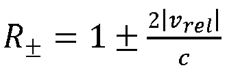
- Radarzielsimulationssystem zum Simulieren mindestens eines sich bewegenden Radarziels, umfassend einen Analog-Digital-Wandler (22) und mindestens einen digitalen Verarbeitungskanal (24), wobei der digitale Verarbeitungskanal (24) mit dem Analog-Digital-Wandler (22) verbunden ist,wobei der digitale Verarbeitungskanal (24) eine Verzögerungseinheit (30), eine Neuabtastungseinheit (32) und eine Frequenzverschiebungseinheit (34) umfasst,wobei die Verzögerungseinheit (30) konfiguriert ist, um ein digitalisiertes Eingangssignal vom Analog-Digital-Wandler (22) zu empfangen und das Eingangssignal mit einer vorgegebenen Zeitverzögerung an die Neuabtastungseinheit (32) und/oder an die Frequenzverschiebungseinheit (34) weiterzuleiten,wobei die Frequenzverschiebungseinheit (34) konfiguriert ist, um eine Frequenz des Eingangssignals basierend auf einer Trägerfrequenz des Eingangssignals und basierend auf einer Geschwindigkeit des zu simulierenden, sich bewegenden Radarziels anzupassen,wobei ein Digital-Analog-Wandler (28) bereitgestellt ist, wobei der Digital-Analog-Wandler (28) mit dem Verarbeitungskanal (24) dem Verarbeitungskanal (24) nachgelagert verbunden ist, wobei der Analog-Digital-Wandler (22) und der Digital-Analog-Wandler (28) die gleiche Abtastfrequenz aufweisen,wobei die Neuabtastungseinheit (32) konfiguriert ist, um das Eingangssignal in der Zeitdomäne und/oder in der Frequenzdomäne basierend auf einer Basisbandfrequenz des Eingangssignals und der Geschwindigkeit des zu simulierenden sich bewegenden Radarziels neu zu skalieren, wobei eine Frequenzachse um einen Faktor
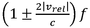

 wobei die Frequenzverschiebungseinheit (34) konfiguriert ist, um die Frequenz des neu skalierten Eingangssignals um
 wobei f0 die Trägerfrequenz ist, f die Basisbandfrequenz ist, vrel die Geschwindigkeit des zu simulierenden, sich bewegenden Radarziels ist und c die Lichtgeschwindigkeit ist.
 - Radarzielsimulationssystem nach Anspruch 1,
dadurch gekennzeichnet, dass die Neuabtastungseinheit (32) konfiguriert ist, um das Eingangssignal in der Zeitdomäne zu verkleinern und/oder in der Frequenzdomäne zu erweitern, wenn sich das zu simulierende Radarziel nähert, und/oder dadurch gekennzeichnet, dass die Neuabtastungseinheit (32) konfiguriert ist, um das Eingangssignal in der Zeitdomäne zu erweitern und/oder in der Frequenzdomäne zu verkürzen, wenn sich das zu simulierende Radarziel entfernt. - Radarzielsimulationssystem nach einem der vorstehenden Ansprüche, dadurch gekennzeichnet, dass die Verzögerungseinheit (30) konfiguriert ist, um das Eingangssignal über eine First-In-First-Out-Technik zu verzögern.
- Radarzielsimulationssystem nach einem der vorstehenden Ansprüche, dadurch gekennzeichnet, dass die Verzögerungseinheit (30) konfiguriert ist, um eine vorgegebene Anzahl von Abtastwerten zu speichern, wobei die vorgegebene Anzahl von Abtastwerten einstellbar ist.
- Radarzielsimulationssystem nach Anspruch 4,
dadurch gekennzeichnet, dass die Verzögerungseinheit (30) konfiguriert ist, um die Anzahl der Abtastwerte basierend auf der Geschwindigkeit des zu simulierenden, sich bewegenden Radarziels anzupassen. - Radarzielsimulationssystem nach einem der vorstehenden Ansprüche, dadurch gekennzeichnet, dass die Neuabtastungseinheit (32) konfiguriert ist, um das Eingangssignal kontinuierlich neu zu skalieren.
- Radarzielsimulationssystem nach einem der vorstehenden Ansprüche, dadurch gekennzeichnet, dass mindestens ein zweiter digitaler Verarbeitungskanal (24) bereitgestellt ist, wobei der zweite digitale Verarbeitungskanal (24) mit dem Analog-Digital-Wandler (22) verbunden ist,wobei der zweite digitale Verarbeitungskanal (24) eine zweite Verzögerungseinheit (30), eine zweite Neuabtastungseinheit (32) und eine zweite Frequenzverschiebungseinheit (34) umfasst,wobei die zweite Verzögerungseinheit (30) konfiguriert ist, um das digitalisierte Eingangssignal vom Analog-Digital-Wandler (22) zu empfangen und das Eingangssignal mit einer vorgegebenen Zeitverzögerung an die zweite Neuabtastungseinheit (32) und/oder an die zweite Frequenzverschiebungseinheit (34) weiterzuleiten,wobei die zweite Frequenzverschiebungseinheit (34) konfiguriert ist, um die Frequenz des Eingangssignals basierend auf der Trägerfrequenz des Eingangssignals und basierend auf einer Geschwindigkeit eines zweiten zu simulierenden, sich bewegenden Radarziels anzupassen, undwobei die zweite Neuabtastungseinheit (32) konfiguriert ist, um das Eingangssignal in der Zeitdomäne und/oder in der Frequenzdomäne basierend auf mindestens einem aus der momentanen Frequenz des Eingangssignals, der Basisbandfrequenz des Eingangssignals, der Trägerfrequenz des Eingangssignals und/oder der Geschwindigkeit des zweiten zu simulierenden, sich bewegenden Radarziels neu zu skalieren.
- Radarzielsimulationssystem nach Anspruch 7,
dadurch gekennzeichnet, dass eine Merging-Einheit (26) vorgesehen ist, wobei die Merging-Einheit (26) mit den Verarbeitungskanälen (24) verbunden und konfiguriert ist, um Ausgangssignale der Verarbeitungskanäle (24) zu überlagern. - Radarzielsimulationssystem nach einem der vorstehenden Ansprüche, dadurch gekennzeichnet, dass die Frequenzverschiebungseinheit (34) als variabler numerisch gesteuerter Oszillator eingerichtet ist.
- Radartestsystem, umfassend eine zu testende Vorrichtung (12) und das Radarzielsimulationssystem (14) nach einem der vorstehenden Ansprüche, wobei die zu testende Vorrichtung (12) ein Radarsystem (16) umfasst.
- Radartestsystem nach Anspruch 10, dadurch gekennzeichnet, dass die zu testende Vorrichtung (12) als Fahrzeugradarsystem (16) eingerichtet ist.
- Verfahren zum Betreiben eines Radarzielsimulationssystems (14) zur Simulation mindestens eines sich bewegenden Radarziels nach einem der Ansprüche 1 bis 9, umfassend die folgenden Schritte:- Erzeugen eines einem Radarsignal zugeordneten Eingangssignals;- Digitalisieren des Eingangssignals;- Verzögern des Eingangssignals um eine vorgegebene Zeitverzögerung, insbesondere über eine First-In-First-Out-Technik;- Anpassen einer Frequenz des Eingangssignals basierend auf einer Trägerfrequenz des Eingangssignals und basierend auf einer Geschwindigkeit des zu simulierenden, sich bewegenden Radarziels; und- Neuskalieren des Eingangssignals in der Zeitdomäne und/oder in der Frequenzdomäne basierend auf einer Basisbandfrequenz des Eingangssignals und basierend auf der Geschwindigkeit des zu simulierenden sich bewegenden Radarziels, wobei eine Frequenzachse um einen Faktor


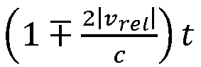 wobei die Frequenz des neu skalierten Eingangssignals um ΔfDoppler,LO =
 wobei f0 die Trägerfrequenz ist, f die Basisbandfrequenz ist, vrel die Geschwindigkeit des zu simulierenden, sich bewegenden Radarziels ist und c die Lichtgeschwindigkeit ist.
 - Verfahren nach Anspruch 12, dadurch gekennzeichnet, dass mindestens zwei sich bewegende Radarziele simuliert werden, wobei die Schritte der Frequenzanpassung und der Frequenzneuskalierung des Eingangssignals für jedes der zu simulierenden Radarziele durchgeführt werden.
Priority Applications (2)
| Application Number | Priority Date | Filing Date | Title |
|---|---|---|---|
| EP19192691.4A EP3783383B1 (de) | 2019-08-20 | 2019-08-20 | Radarzielsimulationssystem, radarprüfsystem und verfahren zum betreiben eines radarzielsimulationssystems |
| US16/935,394 US12025734B2 (en) | 2019-08-20 | 2020-07-22 | Radar target simulation system, radar test system and method for operating a radar target simulation system |
Applications Claiming Priority (1)
| Application Number | Priority Date | Filing Date | Title |
|---|---|---|---|
| EP19192691.4A EP3783383B1 (de) | 2019-08-20 | 2019-08-20 | Radarzielsimulationssystem, radarprüfsystem und verfahren zum betreiben eines radarzielsimulationssystems |
Publications (2)
| Publication Number | Publication Date |
|---|---|
| EP3783383A1 EP3783383A1 (de) | 2021-02-24 |
| EP3783383B1 true EP3783383B1 (de) | 2025-07-09 |
Family
ID=67659545
Family Applications (1)
| Application Number | Title | Priority Date | Filing Date |
|---|---|---|---|
| EP19192691.4A Active EP3783383B1 (de) | 2019-08-20 | 2019-08-20 | Radarzielsimulationssystem, radarprüfsystem und verfahren zum betreiben eines radarzielsimulationssystems |
Country Status (2)
| Country | Link |
|---|---|
| US (1) | US12025734B2 (de) |
| EP (1) | EP3783383B1 (de) |
Families Citing this family (3)
| Publication number | Priority date | Publication date | Assignee | Title |
|---|---|---|---|---|
| CN113109772B (zh) * | 2021-04-07 | 2024-01-30 | 成都信息工程大学 | 一种超宽带高动态目标信号模拟方法 |
| CN113156387B (zh) * | 2021-04-29 | 2023-05-09 | 北京无线电测量研究所 | 一种雷达目标模拟组件和雷达检验方法 |
| CN113822892B (zh) * | 2021-11-24 | 2022-02-08 | 腾讯科技(深圳)有限公司 | 仿真雷达的评测方法、装置、设备及计算机存储介质 |
Family Cites Families (10)
| Publication number | Priority date | Publication date | Assignee | Title |
|---|---|---|---|---|
| US3090955A (en) * | 1960-04-28 | 1963-05-21 | Gen Precision Inc | Test instrument for doppler radar systems |
| DE102006043411B4 (de) * | 2006-09-15 | 2009-11-12 | Innovationszentrum für Telekommunikationstechnik GmbH IZT | Konzept zur realistischen Simulation eines Frequenzspektrums |
| US20100109940A1 (en) * | 2008-10-30 | 2010-05-06 | Peter Robert Williams | Simulating a Radar Signal Reflected From a Moving Target |
| CN104515978B (zh) * | 2013-09-29 | 2018-02-23 | 长春理工大学 | 目标指示雷达目标模拟器 |
| US10317518B2 (en) * | 2015-07-20 | 2019-06-11 | Brigham Young University (Byu) | Phased array radar systems for small unmanned aerial vehicles |
| DE102016121296A1 (de) * | 2016-11-08 | 2018-05-09 | HELLA GmbH & Co. KGaA | Vorrichtung und Verfahren zum Simulieren von Radarzielen |
| IT201700000392A1 (it) * | 2017-01-03 | 2018-07-03 | St Microelectronics Srl | Procedimento per generare segnali di auto-test, circuito ed apparecchiatura corrispondenti |
| US10509107B2 (en) * | 2017-01-13 | 2019-12-17 | Rohde & Schwarz Gmbh & Co. Kg | Device, system and method for simulating at least one echo signal of an electromagnetic signal |
| KR102063468B1 (ko) * | 2018-01-11 | 2020-01-08 | (주)스마트레이더시스템 | 능동형 레이더 모의 타겟 장치 |
| CN109143186A (zh) * | 2018-08-17 | 2019-01-04 | 电子科技大学 | 一种宽带雷达信号多目标远距离模拟装置及方法 |
-
2019
- 2019-08-20 EP EP19192691.4A patent/EP3783383B1/de active Active
-
2020
- 2020-07-22 US US16/935,394 patent/US12025734B2/en active Active
Non-Patent Citations (1)
| Title |
|---|
| UNKOWN: "Doppler Shifting a Chirp Signal", SIGNAL PROCESSING, 1 April 2019 (2019-04-01), internet, XP055949060, Retrieved from the Internet <URL:https://dsp.stackexchange.com/questions/56355/doppler-shifting-a-chirp-signal> [retrieved on 20220804] * |
Also Published As
| Publication number | Publication date |
|---|---|
| US20210055381A1 (en) | 2021-02-25 |
| EP3783383A1 (de) | 2021-02-24 |
| US12025734B2 (en) | 2024-07-02 |
Similar Documents
| Publication | Publication Date | Title |
|---|---|---|
| US10830869B2 (en) | Vehicle radar system and method of calibrating the same | |
| US10754008B2 (en) | Vehicle radar system that addresses doppler frequency shift and method of using the same | |
| US11119185B2 (en) | Resolving doppler ambiguity in multi-input multi-output radar using digital multiple pulse repetition frequencies | |
| US12025734B2 (en) | Radar target simulation system, radar test system and method for operating a radar target simulation system | |
| EP1505408B1 (de) | Verfahren zur SAR- Verarbeitung ohne INS-Dateien | |
| US10627481B2 (en) | Multi-resolution doppler processing | |
| EP2145206B1 (de) | Spotlight-radarsystem mit synthetischer apertur unter verwendung von fpga sowie entsprechendes verfahren | |
| US8022863B1 (en) | Spatially variant apodization (SVA) filter | |
| US11971470B2 (en) | Beamforming hardware accelerator for radar systems | |
| US4462032A (en) | Radar signal processing process and circuit | |
| EP4258010A1 (de) | Kraftfahrzeugradar mit entfernungsmigrationsabschwächungsfunktion | |
| EP3982148B1 (de) | Radarzielsimulator mit kontinuierlicher entfernungsemulation und entsprechendes simulationsverfahren | |
| EP4095558A2 (de) | Radarkommunikation mit überabtastung | |
| US8549060B2 (en) | Concept for realistic simulation of a frequency spectrum | |
| EP2343570A1 (de) | Ausgleich der Bereichsprofilbewegung eines Impulsradars | |
| US20250180697A1 (en) | Radar system implementing segmented chirps and phase compensation for object movement | |
| US6260052B1 (en) | Digital signal processing apparatus and method therefor | |
| US7218272B2 (en) | Reducing antenna boresight error | |
| EP4312058A1 (de) | Eindeutigkeitsbestimmung für geschwindigkeiten für ein radarsensorsystem | |
| US20230408640A1 (en) | System and method for radar range walk compensation in radar systems | |
| EP4249939A1 (de) | Radarempfänger | |
| US20240345238A1 (en) | Method and apparatus for estimating a direction of arrival | |
| US10164815B2 (en) | Extremely precise frequency estimation apparatus and method for single receiver | |
| GB2189362A (en) | A frequency domain correlation system | |
| US20240159888A1 (en) | Radar sensor |
Legal Events
| Date | Code | Title | Description |
|---|---|---|---|
| PUAI | Public reference made under article 153(3) epc to a published international application that has entered the european phase |
Free format text: ORIGINAL CODE: 0009012 |
|
| STAA | Information on the status of an ep patent application or granted ep patent |
Free format text: STATUS: THE APPLICATION HAS BEEN PUBLISHED |
|
| AK | Designated contracting states |
Kind code of ref document: A1 Designated state(s): AL AT BE BG CH CY CZ DE DK EE ES FI FR GB GR HR HU IE IS IT LI LT LU LV MC MK MT NL NO PL PT RO RS SE SI SK SM TR |
|
| AX | Request for extension of the european patent |
Extension state: BA ME |
|
| STAA | Information on the status of an ep patent application or granted ep patent |
Free format text: STATUS: REQUEST FOR EXAMINATION WAS MADE |
|
| 17P | Request for examination filed |
Effective date: 20210806 |
|
| RBV | Designated contracting states (corrected) |
Designated state(s): AL AT BE BG CH CY CZ DE DK EE ES FI FR GB GR HR HU IE IS IT LI LT LU LV MC MK MT NL NO PL PT RO RS SE SI SK SM TR |
|
| STAA | Information on the status of an ep patent application or granted ep patent |
Free format text: STATUS: EXAMINATION IS IN PROGRESS |
|
| 17Q | First examination report despatched |
Effective date: 20220914 |
|
| P01 | Opt-out of the competence of the unified patent court (upc) registered |
Effective date: 20230525 |
|
| GRAP | Despatch of communication of intention to grant a patent |
Free format text: ORIGINAL CODE: EPIDOSNIGR1 |
|
| STAA | Information on the status of an ep patent application or granted ep patent |
Free format text: STATUS: GRANT OF PATENT IS INTENDED |
|
| INTG | Intention to grant announced |
Effective date: 20250429 |
|
| GRAS | Grant fee paid |
Free format text: ORIGINAL CODE: EPIDOSNIGR3 |
|
| GRAA | (expected) grant |
Free format text: ORIGINAL CODE: 0009210 |
|
| STAA | Information on the status of an ep patent application or granted ep patent |
Free format text: STATUS: THE PATENT HAS BEEN GRANTED |
|
| AK | Designated contracting states |
Kind code of ref document: B1 Designated state(s): AL AT BE BG CY CZ DE DK EE ES FI FR GB GR HR HU IS IT LT LU LV MC MK MT NL NO PL PT RO RS SE SI SK SM TR |
|
| RBV | Designated contracting states (corrected) |
Designated state(s): AL AT BE BG CY CZ DE DK EE ES FI FR GB GR HR HU IS IT LT LU LV MC MK MT NL NO PL PT RO RS SE SI SK SM TR |
|
| REG | Reference to a national code |
Ref country code: GB Ref legal event code: FG4D |
|
| REG | Reference to a national code |
Ref country code: DE Ref legal event code: R096 Ref document number: 602019072222 Country of ref document: DE |
|
| PGFP | Annual fee paid to national office [announced via postgrant information from national office to epo] |
Ref country code: DE Payment date: 20250919 Year of fee payment: 7 |
|
| PGFP | Annual fee paid to national office [announced via postgrant information from national office to epo] |
Ref country code: GB Payment date: 20250901 Year of fee payment: 7 |
|
| PGFP | Annual fee paid to national office [announced via postgrant information from national office to epo] |
Ref country code: FR Payment date: 20250902 Year of fee payment: 7 |
|
| REG | Reference to a national code |
Ref country code: NL Ref legal event code: MP Effective date: 20250709 |
|
| PG25 | Lapsed in a contracting state [announced via postgrant information from national office to epo] |
Ref country code: PT Free format text: LAPSE BECAUSE OF FAILURE TO SUBMIT A TRANSLATION OF THE DESCRIPTION OR TO PAY THE FEE WITHIN THE PRESCRIBED TIME-LIMIT Effective date: 20251110 |
|
| PG25 | Lapsed in a contracting state [announced via postgrant information from national office to epo] |
Ref country code: NL Free format text: LAPSE BECAUSE OF FAILURE TO SUBMIT A TRANSLATION OF THE DESCRIPTION OR TO PAY THE FEE WITHIN THE PRESCRIBED TIME-LIMIT Effective date: 20250709 |
|
| REG | Reference to a national code |
Ref country code: AT Ref legal event code: MK05 Ref document number: 1812296 Country of ref document: AT Kind code of ref document: T Effective date: 20250709 |
|
| PG25 | Lapsed in a contracting state [announced via postgrant information from national office to epo] |
Ref country code: IS Free format text: LAPSE BECAUSE OF FAILURE TO SUBMIT A TRANSLATION OF THE DESCRIPTION OR TO PAY THE FEE WITHIN THE PRESCRIBED TIME-LIMIT Effective date: 20251109 |
|
| PG25 | Lapsed in a contracting state [announced via postgrant information from national office to epo] |
Ref country code: NO Free format text: LAPSE BECAUSE OF FAILURE TO SUBMIT A TRANSLATION OF THE DESCRIPTION OR TO PAY THE FEE WITHIN THE PRESCRIBED TIME-LIMIT Effective date: 20251009 |
|
| REG | Reference to a national code |
Ref country code: LT Ref legal event code: MG9D |
|
| PG25 | Lapsed in a contracting state [announced via postgrant information from national office to epo] |
Ref country code: AT Free format text: LAPSE BECAUSE OF FAILURE TO SUBMIT A TRANSLATION OF THE DESCRIPTION OR TO PAY THE FEE WITHIN THE PRESCRIBED TIME-LIMIT Effective date: 20250709 |
|
| PG25 | Lapsed in a contracting state [announced via postgrant information from national office to epo] |
Ref country code: FI Free format text: LAPSE BECAUSE OF FAILURE TO SUBMIT A TRANSLATION OF THE DESCRIPTION OR TO PAY THE FEE WITHIN THE PRESCRIBED TIME-LIMIT Effective date: 20250709 |
|
| PG25 | Lapsed in a contracting state [announced via postgrant information from national office to epo] |
Ref country code: HR Free format text: LAPSE BECAUSE OF FAILURE TO SUBMIT A TRANSLATION OF THE DESCRIPTION OR TO PAY THE FEE WITHIN THE PRESCRIBED TIME-LIMIT Effective date: 20250709 |
|
| PG25 | Lapsed in a contracting state [announced via postgrant information from national office to epo] |
Ref country code: GR Free format text: LAPSE BECAUSE OF FAILURE TO SUBMIT A TRANSLATION OF THE DESCRIPTION OR TO PAY THE FEE WITHIN THE PRESCRIBED TIME-LIMIT Effective date: 20251010 |
|
| PG25 | Lapsed in a contracting state [announced via postgrant information from national office to epo] |
Ref country code: SE Free format text: LAPSE BECAUSE OF FAILURE TO SUBMIT A TRANSLATION OF THE DESCRIPTION OR TO PAY THE FEE WITHIN THE PRESCRIBED TIME-LIMIT Effective date: 20250709 |
|
| PG25 | Lapsed in a contracting state [announced via postgrant information from national office to epo] |
Ref country code: LV Free format text: LAPSE BECAUSE OF FAILURE TO SUBMIT A TRANSLATION OF THE DESCRIPTION OR TO PAY THE FEE WITHIN THE PRESCRIBED TIME-LIMIT Effective date: 20250709 |
|
| PG25 | Lapsed in a contracting state [announced via postgrant information from national office to epo] |
Ref country code: BG Free format text: LAPSE BECAUSE OF FAILURE TO SUBMIT A TRANSLATION OF THE DESCRIPTION OR TO PAY THE FEE WITHIN THE PRESCRIBED TIME-LIMIT Effective date: 20250709 Ref country code: PL Free format text: LAPSE BECAUSE OF FAILURE TO SUBMIT A TRANSLATION OF THE DESCRIPTION OR TO PAY THE FEE WITHIN THE PRESCRIBED TIME-LIMIT Effective date: 20250709 |
|
| PG25 | Lapsed in a contracting state [announced via postgrant information from national office to epo] |
Ref country code: RS Free format text: LAPSE BECAUSE OF FAILURE TO SUBMIT A TRANSLATION OF THE DESCRIPTION OR TO PAY THE FEE WITHIN THE PRESCRIBED TIME-LIMIT Effective date: 20251009 |
|
| PG25 | Lapsed in a contracting state [announced via postgrant information from national office to epo] |
Ref country code: ES Free format text: LAPSE BECAUSE OF FAILURE TO SUBMIT A TRANSLATION OF THE DESCRIPTION OR TO PAY THE FEE WITHIN THE PRESCRIBED TIME-LIMIT Effective date: 20250709 |
|
| PG25 | Lapsed in a contracting state [announced via postgrant information from national office to epo] |
Ref country code: RO Free format text: LAPSE BECAUSE OF FAILURE TO SUBMIT A TRANSLATION OF THE DESCRIPTION OR TO PAY THE FEE WITHIN THE PRESCRIBED TIME-LIMIT Effective date: 20250709 |
|
| PG25 | Lapsed in a contracting state [announced via postgrant information from national office to epo] |
Ref country code: SM Free format text: LAPSE BECAUSE OF FAILURE TO SUBMIT A TRANSLATION OF THE DESCRIPTION OR TO PAY THE FEE WITHIN THE PRESCRIBED TIME-LIMIT Effective date: 20250709 |
|
| PG25 | Lapsed in a contracting state [announced via postgrant information from national office to epo] |
Ref country code: DK Free format text: LAPSE BECAUSE OF FAILURE TO SUBMIT A TRANSLATION OF THE DESCRIPTION OR TO PAY THE FEE WITHIN THE PRESCRIBED TIME-LIMIT Effective date: 20250709 |
|
| PG25 | Lapsed in a contracting state [announced via postgrant information from national office to epo] |
Ref country code: LU Free format text: LAPSE BECAUSE OF NON-PAYMENT OF DUE FEES Effective date: 20250820 Ref country code: IT Free format text: LAPSE BECAUSE OF FAILURE TO SUBMIT A TRANSLATION OF THE DESCRIPTION OR TO PAY THE FEE WITHIN THE PRESCRIBED TIME-LIMIT Effective date: 20250709 |
|
| PG25 | Lapsed in a contracting state [announced via postgrant information from national office to epo] |
Ref country code: CZ Free format text: LAPSE BECAUSE OF FAILURE TO SUBMIT A TRANSLATION OF THE DESCRIPTION OR TO PAY THE FEE WITHIN THE PRESCRIBED TIME-LIMIT Effective date: 20250709 |
|
| PG25 | Lapsed in a contracting state [announced via postgrant information from national office to epo] |
Ref country code: SK Free format text: LAPSE BECAUSE OF FAILURE TO SUBMIT A TRANSLATION OF THE DESCRIPTION OR TO PAY THE FEE WITHIN THE PRESCRIBED TIME-LIMIT Effective date: 20250709 Ref country code: EE Free format text: LAPSE BECAUSE OF FAILURE TO SUBMIT A TRANSLATION OF THE DESCRIPTION OR TO PAY THE FEE WITHIN THE PRESCRIBED TIME-LIMIT Effective date: 20250709 |
|
| PLBE | No opposition filed within time limit |
Free format text: ORIGINAL CODE: 0009261 |
|
| STAA | Information on the status of an ep patent application or granted ep patent |
Free format text: STATUS: NO OPPOSITION FILED WITHIN TIME LIMIT |