EP3783330A1 - Device and method for monitoring at least one sliding bearing - Google Patents
Device and method for monitoring at least one sliding bearing Download PDFInfo
- Publication number
- EP3783330A1 EP3783330A1 EP20191814.1A EP20191814A EP3783330A1 EP 3783330 A1 EP3783330 A1 EP 3783330A1 EP 20191814 A EP20191814 A EP 20191814A EP 3783330 A1 EP3783330 A1 EP 3783330A1
- Authority
- EP
- European Patent Office
- Prior art keywords
- bearing
- pulse
- oscillation frequency
- machine system
- frequency
- Prior art date
- Legal status (The legal status is an assumption and is not a legal conclusion. Google has not performed a legal analysis and makes no representation as to the accuracy of the status listed.)
- Withdrawn
Links
Images


Classifications
-
- G—PHYSICS
- G01—MEASURING; TESTING
- G01M—TESTING STATIC OR DYNAMIC BALANCE OF MACHINES OR STRUCTURES; TESTING OF STRUCTURES OR APPARATUS, NOT OTHERWISE PROVIDED FOR
- G01M13/00—Testing of machine parts
- G01M13/04—Bearings
- G01M13/045—Acoustic or vibration analysis
Definitions
- the present invention relates to a device and a method for monitoring at least one slide bearing.
- Vibration-related methods for bearing monitoring known from the prior art are based on the principle of recognizing damage or impending damage to its typical vibration-related or acoustic signal signatures. For this, the damage frequencies and permissible signal intensities must be known in order to be able to make reliable statements. This method can be implemented very well with ball bearings, since their moving mechanical components stimulate specific frequencies depending on the speed when overflowing any damage. The extent of the damage can also be inferred from the signal strength.
- One from the DE 40 28 559 A1 Known method is based on the measurement of a frequency-selectively processed bearing signal under various operating conditions, e.g. B. signs of abrasion, and the evaluation of this signal by means of a mathematically determined diagnosis number.
- the frequency images are searched for in the event of various faults.
- This method generally requires a reference measurement under the conditions that are to be detected.
- the signal strength is essentially determined by the speed, the size of the contact point, the position of the measuring point, the properties of the lubricant and ultimately the intensity of the contact, and experience has shown that it is very weak in plain bearings.
- the very disadvantage of this method is the fact that the frequencies to be searched for and to be evaluated in this method correspond to the rotational frequency and its multiples.
- the measurement, even directly on the bearing shell, is in practice not isolated from the rest of the machine and is superimposed by natural frequencies in the rest of the machine.
- Residual imbalance, coupling misalignment, symmetrical passing frequencies of the 1st, 2nd, 3rd order, loose or loose connecting elements and much more are usually higher in their signal strength and the same in frequency. This makes it almost impossible to distinguish or isolate the storage frequency (without additional measures) and to assign it to its signal strength without confusion.
- Known methods do not know all harmful frequencies and their structure, the system may not recognize all harmful operating states. Complex: In order to obtain these frequency images, reference measurements are generally necessary under these operating conditions.
- the invention is based on an object to propose a device and a method for monitoring at least one plain bearing, in which the from the Prior art known disadvantages are avoided or at least greatly reduced.
- the method according to the invention has the great advantage that an actual oscillation frequency is monitored during operation, which, if it does not match the first clearly known setpoint oscillation frequency, immediately and unambiguously provides an indication of bearing damage, which is a rapid shutdown of the first plain bearing can follow to avoid major machine damage.
- the effort involved in monitoring a so-called “good frequency” with the first setpoint oscillation frequency is significantly less than inferring a bearing condition from new frequencies that cannot be assigned during operation.
- the actual frequency generated by the plain bearing to be monitored shows during operation whether the plain bearing and the lubricating film are in "good” condition.
- any surface wear can be recognized by the decrease in the signal strength of the target oscillation frequency. The same applies to insufficient lubrication or dry running in the bearing gap. If the signal of the target oscillation frequency can no longer be detected or measured, it can be assumed that it has been destroyed or that there is severe surface wear.
- a particular advantage of this embodiment of the method according to the invention is the possible assignment of different setpoint frequencies for machine systems that have multiple slide bearings. This makes it possible, in this case, to monitor both plain bearings at the same time via their different setpoint frequencies during operation and to monitor a defective bearing of a certain plain bearing due to the difference between its actual oscillation frequency recorded or measured during operation and its set oscillation frequency assigned to it identify exactly.
- frequencies are selected, defined and assigned as target oscillation frequencies which cannot be confused with frequencies occurring in the machine system concerned outside the plain bearings due to its design.
- target oscillation frequencies which cannot be confused with frequencies occurring in the machine system concerned outside the plain bearings due to its design.
- the assigned frequency is searched for, and the simple presence of this frequency means that the status is assessed as "GOOD".
- assigned frequency is meant the modification of the bearings with pulse generators and pulse receivers which, by virtue of their (selected, i.e. assigned) number and speed, result in the desired or selected frequency.
- the signal strength in this context, e.g. to record wear, changes in environmental conditions, dry running, etc. The basis for this would be a reference measurement under the required conditions in order to be able to make precise statements.
- the signal strength is strongly dependent on the respective operating conditions (pressure, temperature, lubricant, etc.) and the design of the pulse generator and pulse receiver arrangement and varies from application to application.
- this is characterized in that the pulse generator and pulse receiver are grooves, bores, depressions, elevations or similar surface changes are formed, the number of pulse generators and pulse receivers differing, but one of the two occurs only once, that is, either one pulse generator and several pulse receivers or several pulse transmitters and one pulse receiver.
- the production of the pulse generator and pulse receiver is advantageously very simple and inexpensive by milling, drilling, grinding, lasering, sintering, casting, coating and all other suitable material application or removal techniques. This embodiment of the device according to the invention is therefore advantageous.
- the rotating element is designed as a pulse generator with thirteen grooves and the stationary element is designed as a pulse receiver with one (numerical one) groove.
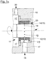
- a kind of test arrangement is shown in the form of a machine system 10 in which a sliding bearing 11 is arranged with a stationary element 12 in the form of a bearing shell and a rotating element 14 in the form of a bearing sleeve.
- the plain bearing 11 is surrounded by a fluid 17, which also serves as bearing lubrication.
- the arrangement can be understood as part of a pump, the fluid 17 representing the conveyed medium which penetrates the bearing essentially according to arrow 20 and leaves the machine system 10 according to arrow 30.
- the rotating element 14 in the form of a bearing sleeve has, for example, thirteen grooves 18, while the stationary element 12 in the form of a bearing shell has a single groove 28. If the bearing sleeve now rotates in relation to the bearing shell, a pulse is generated.
- a vibration meter analyzer 16 is arranged in contact with or in the fluid 17 and can record and process the vibrations prevailing there in accordance with the invention.
- the rotating element 14 in the form of a bearing sleeve can, for example, have thirteen bores 19, while the stationary element 12 in the form of a bearing shell has a single bore 29 ( Fig. 1a ).
- Fig. 2 an arrangement of two radial plain bearings 1 and 2 and two axial plain bearings 3 and 4 in a pump 9 is shown by way of example.
- the bearings 1 and 2 can be made in the manner of the plain bearing 11 Fig. 1 be executed.
- a vibration meter analyzer 16 is arranged in the area of the fluid 17 between the plain bearings 1 and 2.
- a measuring point for the structure-borne noise is provided at the point on the pump outer wall marked with the reference number 8.
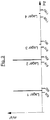
- FIG. 3 to 5 is a frequency spectrum with different states of an exemplary pump according to FIG Fig. 2 shown. A practical application of the invention is described here by way of example.
- the measurement can now be carried out as a structure-borne sound or liquid-borne sound as well as any type of vibration acceleration measurement.
- the sensor of the vibration meter-analyzer is preferably arranged between the bearings in order to obtain approximately the same signal strengths from all bearings.
- the radial bearing pairings deliver their assigned signal during rotation and trouble-free operation. Due to the design, the axial bearings in this pump are in normal operation no contact. The reason for this is a hydraulic compensation system that forces the shaft into a central position. As a result, the signals from bearings 3 and 4 generate no or only a very weak signal due to the increased distance from one another.
- Fig. 3 shows the normal or good state in the frequency spectrum for this pump.
- pulse generator and “pulse receiver” used here relate to desired surface changes in the bearing shell and bearing sleeve, which can be produced with the measures described below.
- the terms are not technically common designations, they are intended to facilitate understanding in the overall context.
- the surfaces of the contact areas of the plain bearing pairings bearing shell - bearing sleeve are structured on both sides. One side with a large number of "pulse generators”, the other surface with only one "pulse receiver”. It does not matter whether this is done on the rotating or stationary bearing.
- Pulse generators and pulse receivers can be implemented by means of grooves, bores, depressions, elevations or similar deliberately produced surface changes. Due to the locally stable signal transmission to the vibration meter analyzer 16 ( Fig. 1 ) in most cases (as here) the stationary bearing shell is designed as an impulse receiver. Pulse transmitters or receivers can be produced by milling, drilling, grinding, laser cutting, sintering, casting, coating and all other suitable material application or removal techniques.
- pulse generator and "pulse receiver” are not standardized, generally technically common descriptions. In this context, they only serve to simplify the description and are in no way related to complex instruments, sensors or components on the market. Since the possibilities for generating pulses for the method are very extensive, in the absence of an alternative, more suitable collective term for these devices, the terms “pulse generator” and “pulse receiver” are considered to be understandable and clear.
- the initiators, resp. Grooves 18 are variable in number and can be selected individually for the application. In this way, in the event of an overflow, they generate the defined and assigned target frequency of the respective bearing pairing.
- a single surface structure in the form of the groove 28 is introduced or applied to the contact surface of the stationary bearing shell.
- the measurable detection frequency (target oscillation frequency) of the relevant plain bearing results from the number of pulse generators on the circumference of the bearing and the speed when the machine is in operation.
- target oscillation frequency the measurable detection frequency of the relevant plain bearing
- the signal strength (pulse strength) can be changed or optimized for the respective application.
- Options for signal optimization are e.g. B. Arrangement of resonance chambers on the pulse generator / receiver, the flow of lubricant through the pulse generator / receiver and an increase in pressure of the lubricant in the contact area, etc.
- the frequency of the pulse measurement values is changed and can thus be assigned to the bearing pairing (target vibration frequency) as a clear, individual vibration signal.
- those frequencies are selected, defined and assigned as setpoint oscillation frequencies which cannot be confused with frequencies occurring in the machine system concerned due to its construction.
- the advantage - as already emphasized above - is obvious: imbalances, misalignments, shovel passing or rollover frequencies and their multiples can be avoided and almost any misinterpretation can be excluded.
- Prime number arrangements for generating pulses per revolution of the bearing sleeve are also suitable for identifying and delimiting them from other frequency signals, i.e. H. of the pulse generator 14 good.
- a bearing sleeve with thirteen pulses per revolution generates a bearing frequency of 628.3 Hz (2900/60 x 13) in a machine that runs at 2900 revolutions per minute. At 3500 revolutions per minute the bearing frequency is 758.3 Hz, etc.
- a detection or reaction range of the measuring devices can be defined, which of course corresponds to the load-dependent speed range of the machine (usually +/- 2% of the nominal value). If variable-speed drive machines are used, speed feedback (frequency converter, motor sensor) can be integrated.
- the rotational frequency can also be set in the machine as the strongest frequency signal using the "pulse generation" method and thus serve as a calculation basis for the measuring electronics and software.
- An essential advantage of the present invention is the structurally freely selectable frequency, implemented by the number of pulse generators that the undamaged bearing is to generate. This allows frequencies to be set that are not naturally excited in this machine / arrangement. It is thus possible to place the frequencies generated and to be evaluated in a range of the frequency spectrum in which normally only the background noise dominates (eg usually F> 600 Hz in pump construction). This makes the distinction of each one of a large number of plain bearings in a complex machine or machine arrangement.
- the signal strength can also be regulated.
- no reference measurements are necessary for the pure function monitoring of plain bearings, since only the simple presence of the (measurable) signal at the assigned frequency is sufficient to make an assessment "OK” or, in the absence of this signal, "not OK".
- the method according to the invention detects a completely missing bearing (no signal). Ceramic bearings can also be safely monitored for sudden breakage.
- the signal strength can be influenced (in terms of production technology) and can thus be optimized for measurement and evaluation.
- the method according to the invention does not require any reference measurements for the operating states to be recognized and empirically determined values.
- the process can be reproduced without any problems and can be used for all bearing sizes, speeds and environmental conditions.
- the influence of the ambient conditions (materials, lubricants, temperature %) can be assessed as negligible compared to other methods
Abstract
Verfahren zur Überwachung wenigstens eines ersten Gleitlagers im Betrieb, mit folgenden Schritten: - Definieren und Zuordnen einer ersten Soll-Schwingfrequenz für das zu überwachende Lager, welche von dem ersten zu überwachenden Lager im laufenden Betrieb mechanisch oder hydraulisch erzwungen und drehzahlabhängig erzeugt wird, - Aufnehmen einer ersten Ist-Schwingfrequenz im laufenden Betrieb des ersten Gleitlagers mit einer Messvorrichtung, - Vergleichen der ersten Ist-Schwingfrequenz mit der ersten Soll-Schwingfrequenz.A method for monitoring at least one first plain bearing during operation, with the following steps: defining and assigning a first setpoint oscillation frequency for the bearing to be monitored, which is mechanically or hydraulically forced by the first bearing to be monitored during operation and is generated as a function of the speed, recording a first actual oscillation frequency during operation of the first plain bearing with a measuring device, - comparison of the first actual oscillation frequency with the first target oscillation frequency.
Description
Die vorliegende Erfindung betrifft eine Vorrichtung und ein Verfahren zur Überwachung wenigstens eines Gleitlagers.The present invention relates to a device and a method for monitoring at least one slide bearing.
Aus dem Stand der Technik bekannte schwingungstechnische Methoden zur Lagerüberwachung basieren auf dem Prinzip der Erkennung eines Schadens oder sich anbahnenden Schadens an seinen typischen schwingungstechnischen oder akustischen Signalsignaturen. Dafür müssen die Schadensfrequenzen und zulässigen Signalintensitäten bekannt sein, um zuverlässige Aussagen treffen zu können. Diese Methode ist sehr gut bei Kugellagern umsetzbar, da deren bewegte mechanische Bauteile bei Überlauf eines etwaigen Schadens drehzahlabhängig spezifische Frequenzen anregen. Aus der Signalstärke kann auch auf das Ausmaß des Schadens geschlossen werden.Vibration-related methods for bearing monitoring known from the prior art are based on the principle of recognizing damage or impending damage to its typical vibration-related or acoustic signal signatures. For this, the damage frequencies and permissible signal intensities must be known in order to be able to make reliable statements. This method can be implemented very well with ball bearings, since their moving mechanical components stimulate specific frequencies depending on the speed when overflowing any damage. The extent of the damage can also be inferred from the signal strength.
Bei Gleitlagern ist es dagegen schwierig, eine eindeutige, verwechslungsfreie Schadensfrequenz zu definieren. Da z. B. beim Bruch eines Lagers oder bei einem Oberflächenverschleiß kein reproduzierbarer Schwingungsverlauf vorhersagbar ist, kann auch im Gesamtschwingungsspektrum einer Maschine ein defektes Gleitlager nicht oder nur mit Schwierigkeiten identifiziert werden. Meist geben Erfahrungswerte oder empirisch ermittelte Werte einen einzigen aber auch nicht eindeutig sicheren Anhaltspunkt. Diese Vorgehensweise ist außerdem aufwändig und erfordert umfangreiches Wissen im Bereich der Schwingungstechnik, der mechanischen Komponenten sowie der hydraulischen Abläufe im Lagerspalt.In the case of plain bearings, on the other hand, it is difficult to define a clear, unmistakable damage frequency. Since z. If, for example, no reproducible vibration curve is predictable in the event of a bearing break or surface wear, a defective plain bearing cannot be identified in the overall vibration spectrum of a machine, or only with difficulty. Mostly empirical values or empirically determined values give a single but also not clearly reliable reference point. This procedure is also complex and requires extensive knowledge in the area of vibration technology, mechanical components and hydraulic processes in the bearing gap.
Erschwerend kommt der Umstand hinzu, dass eine solche Vorgehensweise letztendlich keine klaren allgemeingültigen Aussagen liefert und sich damit nur sehr begrenzt auf andere Gleitlager bzw. Konstruktionen übertragen lässt.A further complicating factor is the fact that such a procedure ultimately does not provide any clear, generally applicable statements and can therefore only be transferred to other plain bearings or designs to a very limited extent.
Ein aus der
Sehr nachteilig ist bei diesem Verfahren die Tatsache, dass die gesuchten und zu bewertenden Frequenzen in diesem Verfahren der Drehfrequenz und deren Vielfachen entspricht. Die Messung, selbst direkt an der Lagerschale, ist in der Praxis nicht isoliert von der restlichen Maschine und wird durch natürliche Frequenzen in der restlichen Maschine überlagert. Restunwucht, Kupplungsfehlausrichtung, symmetrische Passierfrequenzen der 1., 2., 3. Ordnung, lose oder lockere Verbindungselemente und vieles mehr sind in Ihrer Signalstärke üblicherweise höher und in der Frequenz gleich. Dadurch ist es nahezu unmöglich, die Lagerfrequenz (ohne zusätzliche Maßnahmen) zu unterscheiden bzw. isolieren und ihrer Signalstärke verwechslungsfrei zuzuordnen. Sind bei dem aus der
Insbesondere bei Gleitlagern mit keramischen Lagerwerkstoffen ist ein plötzlicher Bruch der rotierenden Teile bei Überlastung (z.B. wegen zerbrochener und ausgespülter Keramik oder infolge von Montagefehlern) ein häufiger Ausfallgrund und führt zu nicht näher definierbaren chaotischen Signalbildern.In the case of plain bearings with ceramic bearing materials in particular, a sudden break in the rotating parts when overloaded (e.g. due to broken and flushed ceramics or as a result of assembly errors) is a frequent cause of failure and leads to chaotic signal patterns that cannot be further defined.
Der Erfindung liegt eine Aufgabe zugrunde, eine Vorrichtung und ein Verfahren zur Überwachung wenigstens eines Gleitlagers vorzuschlagen, bei welchen die aus dem Stand der Technik bekannten Nachteile vermieden oder wenigstens stark vermindert werden.The invention is based on an object to propose a device and a method for monitoring at least one plain bearing, in which the from the Prior art known disadvantages are avoided or at least greatly reduced.
Die Aufgabe wird zunächst gelöst mit einem Verfahren gemäß Anspruch 1, nämlich einem Verfahren zur Überwachung wenigstens eines ersten Gleitlagers im Betrieb, mit folgenden Schritten:
- a1) Definieren und Zuordnen einer ersten Soll-Schwingfrequenz für das zu überwachende Lager, welche von dem ersten zu überwachenden Lager im laufenden Betrieb mechanisch oder hydraulisch erzwungen und drehzahlabhängig erzeugt wird,
- b1) Aufnehmen einer ersten Ist-Schwingfrequenz im laufenden Betrieb des ersten Gleitlagers mit einer Messvorrichtung,
- c1) Vergleichen der ersten Ist-Schwingfrequenz mit der ersten Soll-Schwingfrequenz.
- a1) Defining and assigning a first target oscillation frequency for the bearing to be monitored, which is mechanically or hydraulically enforced by the first bearing to be monitored during operation and generated as a function of the speed,
- b1) recording a first actual vibration frequency during operation of the first plain bearing with a measuring device,
- c1) comparing the first actual oscillation frequency with the first setpoint oscillation frequency.
Das erfindungsgemäße Verfahren hat den großen Vorteil, dass im laufenden Betrieb eine Ist-Schwingfrequenz überwacht wird, welche sofern sie nicht mit der ersten eindeutig bekannten Soll-Schwingfrequenz übereinstimmt, sofort und eindeutig ein Indiz für einen Lagerschaden ergibt, welchem ein schnelles Stillsetzen des ersten Gleitlagerns folgen kann, um größeren Maschinenschaden zu vermeiden. Der Aufwand, mit der ersten Soll-Schwingfrequenz eine sog. "Gut-Frequenz" zu überwachen ist wesentlich geringer als aus im Betrieb neu entstehenden nicht zuordenbaren Frequenzen auf einen Lagerzustand zu schließen. Die vom zu überwachenden Gleitlager erzeugte Ist-Frequenz zeigt im laufenden Betrieb, ob Gleitlager und Schmierfilm in "gutem" Zustand sind. Gleichzeitig kann ein eventueller Oberflächenverschleiß durch die Abnahme der Signalstärke der Soll-Schwingfrequenz erkannt werden. Gleiches gilt für Mangelschmierung oder Trockenlauf im Lagerspalt. Ist das Signal der Soll-Schwingfrequenz nicht mehr nachweisbar bzw. messbar, kann von einer Zerstörung oder starkem Oberflächenverschleiß ausgegangen werden.The method according to the invention has the great advantage that an actual oscillation frequency is monitored during operation, which, if it does not match the first clearly known setpoint oscillation frequency, immediately and unambiguously provides an indication of bearing damage, which is a rapid shutdown of the first plain bearing can follow to avoid major machine damage. The effort involved in monitoring a so-called “good frequency” with the first setpoint oscillation frequency is significantly less than inferring a bearing condition from new frequencies that cannot be assigned during operation. The actual frequency generated by the plain bearing to be monitored shows during operation whether the plain bearing and the lubricating film are in "good" condition. At the same time, any surface wear can be recognized by the decrease in the signal strength of the target oscillation frequency. The same applies to insufficient lubrication or dry running in the bearing gap. If the signal of the target oscillation frequency can no longer be detected or measured, it can be assumed that it has been destroyed or that there is severe surface wear.
In einer vorteilhaften Ausbildung des erfindungsgemäßen Verfahrens ist dieses dadurch gekennzeichnet, dass es zur Überwachung wenigstens eines zweiten Gleitlagers im Betrieb folgende Schritte aufweist,
- a2) Definieren und Zuordnen einer zweiten von der ersten verschiedenen Soll-Schwingfrequenz für wenigstens das zweite zu überwachende Gleitlager, welche von dem zweiten zu überwachenden Lager im laufenden Betrieb mechanisch oder hydraulisch erzwungen und drehzahlabhängig erzeugt wird,
- b2) Aufnehmen einer zweiten Ist-Schwingfrequenz im laufenden Betrieb des zweiten Gleitlagers mit einer Messvorrichtung,
- c2) Vergleichen der zweiten Ist-Schwingfrequenz mit der zweiten Soll-Schwingfrequenz.
- a2) Defining and assigning a second setpoint oscillation frequency different from the first for at least the second plain bearing to be monitored, which of the second bearing to be monitored during operation mechanically or hydraulically forced and generated depending on the speed,
- b2) recording a second actual oscillation frequency during operation of the second plain bearing with a measuring device,
- c2) comparing the second actual oscillation frequency with the second setpoint oscillation frequency.
Ein besonderer Vorteil dieser Ausbildung des erfindungsgemäßen Verfahrens ist die mögliche Zuordnung verschiedener Soll-Frequenzen für Maschinensysteme, die mehrere Gleitlager aufweisen. Dadurch ist es möglich, in diesem Fall gleichzeitig beide Gleitlager über deren verschiedene Soll-Frequenzen im laufenden Betrieb zu überwachen und ein schadhaftes Lager eines bestimmten Gleitlagers aufgrund der Differenz seiner im laufenden Betrieb aufgenommenen bzw. gemessenen Ist-Schwingfrequenz gegenüber seiner ihm zugeordneten Soll-Schwingfrequenz genau zu identifizieren.A particular advantage of this embodiment of the method according to the invention is the possible assignment of different setpoint frequencies for machine systems that have multiple slide bearings. This makes it possible, in this case, to monitor both plain bearings at the same time via their different setpoint frequencies during operation and to monitor a defective bearing of a certain plain bearing due to the difference between its actual oscillation frequency recorded or measured during operation and its set oscillation frequency assigned to it identify exactly.
In einer weiteren vorteilhaften Ausbildung des erfindungsgemäßen Verfahrens ist dieses dadurch gekennzeichnet, dass als Soll-Schwingfrequenzen solche Frequenzen ausgewählt, definiert und zugeordnet werden, die nicht mit in dem betroffenen Maschinensystem außerhalb der Gleitlager aufgrund seiner Konstruktion auftretenden Frequenzen verwechselt werden können. Der Vorteil liegt auf der Hand: Unwuchten, Fehlausrichtungen, Schaufelpassier- oder Überrollfrequenzen und deren Vielfache können vermieden und damit nahezu jegliche Fehlinterpretationen ausgeschlossen werden. Hierbei eignen sich für die Erkennbarkeit und Abgrenzung zu anderen Frequenzsignalen auch Primzahlanordnungen gut.In a further advantageous embodiment of the method according to the invention, it is characterized in that frequencies are selected, defined and assigned as target oscillation frequencies which cannot be confused with frequencies occurring in the machine system concerned outside the plain bearings due to its design. The advantage is obvious: imbalances, misalignments, shovel passing or rollover frequencies and their multiples can be avoided and almost any misinterpretation can be excluded. Prime number arrangements are also well suited for recognizing and distinguishing from other frequency signals.
Die Aufgabe wird weiterhin gelöst mit einer Vorrichtung gemäß Anspruch 4, nämlich einer Vorrichtung zur Überwachung wenigstens eines in einem Maschinensystem angeordneten Gleitlagers mit einem feststehenden Element und einem rotierenden Element, insbesondere nach einem Verfahren gemäß einem der oben diskutierten Verfahrensansprüche, die gekennzeichnet ist durch folgende Merkmale:
- a) das rotierende Element weist einen Impulsgeber auf,
- b) das am Maschinensystem befestigt angeordnete feststehende Element weist einen Impulsempfänger auf,
- c) im Bereich des Maschinensystems ist ein Schwingungsmesser-Analysator angeordnet.
- a) the rotating element has a pulse generator,
- b) the fixed element attached to the machine system has a pulse receiver,
- c) A vibration meter analyzer is arranged in the area of the machine system.
Mit der erfindungsgemäßen Vorrichtung kann höchst unkompliziert eine Gut-Frequenzmessung durchgeführt werden. Die Herstellung von Impulsgeber und Impulsempfänger ist ebenfalls kostengünstig und einfach.With the device according to the invention, a good frequency measurement can be carried out in a very uncomplicated manner. The production of the pulse generator and pulse receiver is also inexpensive and simple.
Die Aufgabe wird ebenfalls weiterhin gelöst mit einer Vorrichtung gemäß Anspruch 5, nämlich einer Vorrichtung zur Überwachung wenigstens eines in einem Maschinensystem angeordneten Gleitlagers mit einem feststehenden Element und einem rotierenden Element, insbesondere nach einem Verfahren gemäß einem der oben diskutierten Verfahrensansprüche, die gekennzeichnet ist durch folgende Merkmale:
- a) das rotierende Element weist einen Impulsempfänger auf,
- b) das am Maschinensystem befestigt angeordnete feststehende Element weist einen Impulsgeber auf,
- c) im Bereich des Maschinensystems ist ein Schwingungsmesser-Analysator angeordnet.
- a) the rotating element has a pulse receiver,
- b) the fixed element attached to the machine system has a pulse generator,
- c) A vibration meter analyzer is arranged in the area of the machine system.
Hier sind die Komponenten Impulsempfänger und Impulsgeber in der Vorrichtung vertauscht angeordnet. Sie bietet die gleichen Vorteile wie die der zuvor beschriebenen Vorrichtung.Here the components of the pulse receiver and pulse generator are reversed in the device. It offers the same advantages as those of the device described above.
Erfindungsgemäß wird nach der zugeordneten Frequenz gesucht, und durch das schlichte Vorhandensein dieser Frequenz wird die Beurteilung des Zustandes als "GUT" bewertet.According to the invention, the assigned frequency is searched for, and the simple presence of this frequency means that the status is assessed as "GOOD".
Mit "zugeordneter Frequenz" ist die Modifikation der Lager mit Impulsgebern und Impulsempfängern gemeint, die durch ihre (gewählte, d. h. zugeordnete) Anzahl und der Drehzahl die gesuchte bzw. gewählte Frequenz ergibt.With "assigned frequency" is meant the modification of the bearings with pulse generators and pulse receivers which, by virtue of their (selected, i.e. assigned) number and speed, result in the desired or selected frequency.
Zusätzlich könnte man in diesem Zuge auch die Signalstärke bewerten, um z.B.: Verschleiß, Änderung von Umgebungsbedingungen, Trockenlauf usw. zu erfassen. Grundlage hierfür wäre eine Referenzmessung unter den gesuchten Bedingungen, um präzise Aussagen tätigen zu können. Die Signalstärke ist stark abhängig von den jeweiligen Betriebsbedingungen (Druck, Temperatur, Schmierflüssigkeit usw.) und der Ausführung der Impulsgeber- und Impulsempfängeranordnung und variiert von Anwendung zu Anwendung.In addition, one could also evaluate the signal strength in this context, e.g. to record wear, changes in environmental conditions, dry running, etc. The basis for this would be a reference measurement under the required conditions in order to be able to make precise statements. The signal strength is strongly dependent on the respective operating conditions (pressure, temperature, lubricant, etc.) and the design of the pulse generator and pulse receiver arrangement and varies from application to application.
In einer vorteilhaften Ausbildung der erfindungsgemäßen Vorrichtung ist diese dadurch gekennzeichnet, dass die Impulsgeber und Impulsempfänger als Nuten, Bohrungen, Vertiefungen, Erhöhungen oder ähnliche Oberflächenveränderungen ausgebildet sind, wobei sich die Anzahl der Impulsgeber und Impulsempfänger unterscheidet, einer der beiden jedoch nur einmal auftritt, also entweder ein Impulsgeber und mehrere Impulsempfänger oder mehrere Impulsgeber und ein Impulsempfänger.In an advantageous embodiment of the device according to the invention, this is characterized in that the pulse generator and pulse receiver are grooves, bores, depressions, elevations or similar surface changes are formed, the number of pulse generators and pulse receivers differing, but one of the two occurs only once, that is, either one pulse generator and several pulse receivers or several pulse transmitters and one pulse receiver.
Die Herstellung von Impulsgeber und Impulsempfänger ist vorteilhafterweise sehr einfach und kostengünstig durch fräsen, bohren, schleifen, lasern, sintern, gießen, beschichten und alle anderen geeigneten Materialauftrags- bzw. -abtragstechniken möglich. Damit ist diese erfindungsgemäße Ausbildung der Vorrichtung von Vorteil.The production of the pulse generator and pulse receiver is advantageously very simple and inexpensive by milling, drilling, grinding, lasering, sintering, casting, coating and all other suitable material application or removal techniques. This embodiment of the device according to the invention is therefore advantageous.
In einer weiteren vorteilhaften Ausbildung der erfindungsgemäßen Vorrichtung ist diese dadurch gekennzeichnet, dass das rotierende Element als Impulsgeber mit dreizehn Nuten und das feststehende Element als Impulsempfänger mit einer (Zahlwort eins) Nut ausgebildet ist.In a further advantageous embodiment of the device according to the invention, it is characterized in that the rotating element is designed as a pulse generator with thirteen grooves and the stationary element is designed as a pulse receiver with one (numerical one) groove.
Um nun eine klare Aussage über den Zustand einzelner Gleitlagerkomponenten zu erlangen, wird hier ein Verfahren zur Zustandsüberwachung an rotierenden Gleitlagern mittels schwingungstechnischer- oder akustischer Frequenzanalyse beschrieben. Bei dieser Methode wird erfindungsgemäß nicht nach typischen Schadensfrequenzen gesucht und diese bewertet, sondern es wird durch geeignete Maßnahmen wie Impulserzeugung der Gleitlagerpaarung eine Schwingfrequenz zugeordnet, die sich im Betrieb mechanisch, hydraulisch erzwungen und drehzahlabhängig ergibt.In order to obtain a clear statement about the condition of individual slide bearing components, a method for monitoring the condition of rotating slide bearings by means of vibration or acoustic frequency analysis is described here. In this method, according to the invention, typical damage frequencies are not searched for and evaluated, but rather an oscillation frequency is assigned to the sliding bearing pairing by means of suitable measures such as pulse generation, which is mechanically, hydraulically enforced and speed-dependent during operation.
Im Folgenden wird die Erfindung um zu zeigen, wie ausgeführt werden kann und zum leichteren Verständnis anhand eines Ausführungsbeispiels einer erfindungsgemäßen Vorrichtung mittels einer Zeichnung und weitere Erklärungen kurz beschrieben.
- Fig. 1
- zeigt stark schematisiert und vereinfacht die Darstellung der wesentlichen Elemente eines Maschinensystems, in welchem eine Ausführungsform einer erfindungsgemäßen Vorrichtung angeordnet ist, im Teilschnitt.
- Fig. 1a
- zeigt stark schematisiert und vereinfacht ein Maschinensystem gemäß
Fig. 1 , in welchem jedoch die Impulsgeber und der Impulsempfänger als Bohrungen ausgeführt sind. - Fig. 2
- zeigt stark schematisiert und vereinfacht die Darstellung einer Pumpe, in welcher eine Ausführungsform einer erfindungsgemäßen Vorrichtung mehrfach angeordnet ist, im Teilschnitt.
- Fig. 3
- zeigt eine Tabelle mit dem Normal- bzw. Gutzustand im Frequenzspektrum für eine Pumpe gemäß
Fig. 2 . - Fig. 4
- zeigt eine Tabelle
mit Lagerbruch Lager 1 im Frequenzspektrum für eine Pumpe gemäßFig. 2 . - Fig. 5
- zeigt eine Tabelle
mit Lagerüberlastung Lager 3 im Frequenzspektrum für eine Pumpe gemäßFig. 2 .
- Fig. 1
- shows, in a highly schematic and simplified manner, the representation of the essential elements of a machine system in which an embodiment of a device according to the invention is arranged, in partial section.
- Fig. 1a
- shows in a highly schematic and simplified manner a machine system according to FIG
Fig. 1 , in which, however, the pulse generator and the pulse receiver are designed as bores. - Fig. 2
- shows a highly schematic and simplified representation of a pump in which an embodiment of a device according to the invention is arranged several times, in partial section.
- Fig. 3
- shows a table with the normal or good condition in the frequency spectrum for a pump according to
Fig. 2 . - Fig. 4
- shows a table with bearing breakage bearing 1 in the frequency spectrum for a pump according to
Fig. 2 . - Fig. 5
- shows a table with bearing overload bearing 3 in the frequency spectrum for a pump according to
Fig. 2 .
In
Analog hierzu kann in einem anderen Ausführungsbeispiel das rotierende Element 14 in Form einer Lagerhülse beispielsweise dreizehn Bohrungen 19 tragen, während das feststehende Element 12 in Form einer Lagerschale eine einzige Bohrung 29 aufweist (
In
In den
In mit einer Magnetkupplung zur Kraftübertragung ausgestatteten Pumpen müssen durch ein Fördermedium geschmierte Gleitlager eingesetzt werden, welche die rotierende Welle zentrieren und radiale sowie axiale Kräfte aufnehmen. Dafür sind im Allgemeinen vier einzelne Lagerstellen erforderlich, wie hier gezeigt zwei Axiallager und zwei Radiallager. Die Nenndrehzahl liegt bei dieser beispielhaften Maschine bei 2950 Umdrehungen pro Minute und wird durch einen 3-Phasen-Asynchron-Elektromotor erzeugt. Der lastabhängige Schlupf dieses Motors ist +/- 2%.In pumps equipped with a magnetic coupling for power transmission, slide bearings lubricated by a pumping medium must be used, which center the rotating shaft and absorb radial and axial forces. This generally requires four individual bearing points, as shown here two axial bearings and two radial bearings. The nominal speed of this exemplary machine is 2950 revolutions per minute and is generated by a 3-phase asynchronous electric motor. The load-dependent slip of this motor is +/- 2%.
Die Messung kann nun als Körperschall- oder Flüssigkeitsschall- sowie jede Art von Schwingbeschleunigungsmessung ausgeführt sein. Der Sensor des Schwingungsmesser-Analysators ist vorzugsweise zwischen den Lagern angeordnet, um annähernd gleiche Signalstärken von allen Lagern zu erhalten.The measurement can now be carried out as a structure-borne sound or liquid-borne sound as well as any type of vibration acceleration measurement. The sensor of the vibration meter-analyzer is preferably arranged between the bearings in order to obtain approximately the same signal strengths from all bearings.
In diesem Beispiel sind den Lagern 1 bis 4 durch oben beschriebene Maßnahmen individuelle Frequenzen zugeordnet worden:
- Radiallagerpaarung pumpenseitig: 13 Impulse pro Umdrehung (Lager 1)
- Radiallagerpaarung antriebsseitig: 17 Impulse pro Umdrehung (Lager 2)
- Axiallagerpaarung pumpenseitig: 19 Impulse pro Umdrehung (Lager 3)
- Axiallagerpaarung antriebsseitig: 23 Impulse pro Umdrehung (Lager 4)
- Radial bearing pairing on the pump side: 13 pulses per revolution (bearing 1)
- Radial bearing pairing on the drive side: 17 pulses per revolution (bearing 2)
- Axial bearing pairing on the pump side: 19 pulses per revolution (bearing 3)
- Axial bearing pairing on the drive side: 23 pulses per revolution (bearing 4)
Daraus ergeben sich folgende Überlauffrequenzen und ein lastabhängiger Streubereich von:
Drehzahlstreubereich = 3009 bis 2891 Umdrehungen pro Minute
Lager 1 = 651,95Hz bis 626,34 HzLager 2 = 852,55Hz bis 819,06 HzLager 3 = 952,85Hz bis 915,42 HzLager 4 = 1153,45Hz bis
Speed deviation range = 3009 to 2891 revolutions per minute
-
Bearing 1 = 651.95 Hz to 626.34 Hz -
Bearing 2 = 852.55 Hz to 819.06 Hz -
Bearing 3 = 952.85 Hz to 915.42 Hz -
Bearing 4 = 1153.45 Hz to 1108.14 Hz
Die Radiallagerpaarungen liefern bei Rotation und störungsfreiem Betrieb ihr zugewiesenes Signal. Bauartbedingt haben die Axiallager in dieser Pumpe im Normalbetrieb keinen Kontakt. Grund hierfür ist ein hydraulisches Ausgleichssystem, das die Welle in eine Mittelstellung zwingt. Dies führt dazu, dass die Signale von Lager 3 und 4 durch den erhöhten Abstand voneinander kein oder nur ein sehr schwaches Signal erzeugen.The radial bearing pairings deliver their assigned signal during rotation and trouble-free operation. Due to the design, the axial bearings in this pump are in normal operation no contact. The reason for this is a hydraulic compensation system that forces the shaft into a central position. As a result, the signals from
Fällt Lager 1 durch Bruch aus, verändert sich das Spektrum in der Frequenzanalyse gemäß
Wird der hydraulische Ausgleich gestört und das Lager 3 dadurch axial belastet, erhält man Signale nach
Das Fehlen eines Schmierstoffes erzeugt eine Veränderung im Schwingspektrum. Trockenlauf kann somit ebenfalls erkannt werden. Denkbar ist auch die Erkennung von Kavitation innerhalb der Lager / Pumpe. Diese Möglichkeiten sind jedoch abhängig von den Eigenschaften des Schmierstoffes sowie der Messmethode und müssen für den Einzelfall betrachtet werden. Weitere Möglichkeiten der Schadens- bzw. Fehlfunktionserkennung sind selbsterklärend. In allen als Schadensfall erkannten Situationen kann die jeweilige Maschine kurzfristig stillgesetzt werden, um größeren Schaden zu vermeiden.The lack of a lubricant creates a change in the vibration spectrum. Dry running can thus also be recognized. The detection of cavitation within the bearing / pump is also conceivable. However, these options depend on the properties of the lubricant and the measurement method and must be considered on a case-by-case basis. Further possibilities of damage or malfunction detection are self-explanatory. In all situations identified as damage, the respective machine can be shut down for a short time in order to avoid greater damage.
Im Folgenden werden geeignete Maßnahmen zur drehzahlabhängigen Impulserzeugung in rotierenden, flüssigkeitsgeschmierten Gleitlagern zur Überwachung mittels schwingungstechnischer bzw. akustischer Frequenzanalyse diskutiert.In the following, suitable measures for speed-dependent pulse generation in rotating, liquid-lubricated plain bearings for monitoring by means of vibration-related or acoustic frequency analysis are discussed.
Die hier verwendeten Begriffe "Impulsgeber" und "Impulsempfänger" beziehen sich auf gewollte Oberflächenveränderungen in Lagerschale und Lagerhülse, die mit unten beschriebenen Maßnahmen hergestellt werden können. Die Begriffe sind keine technisch üblichen Bezeichnungen, sie sollen vielmehr das Verständnis im Gesamtzusammenhang erleichtern.The terms "pulse generator" and "pulse receiver" used here relate to desired surface changes in the bearing shell and bearing sleeve, which can be produced with the measures described below. The terms are not technically common designations, they are intended to facilitate understanding in the overall context.
Die Oberflächen der Kontaktbereiche der Gleitlagerpaarungen Lagerschale - Lagerhülse werden beidseitig strukturiert. Die eine Seite mit einer Vielzahl von "Impulsgebern", die andere Oberfläche mit nur einem "Impulsempfänger". Dabei spielt es eine untergeordnete Rolle, ob dies am rotierenden oder feststehenden Lager geschieht.The surfaces of the contact areas of the plain bearing pairings bearing shell - bearing sleeve are structured on both sides. One side with a large number of "pulse generators", the other surface with only one "pulse receiver". It does not matter whether this is done on the rotating or stationary bearing.
Impulsgeber und Impulsempfänger können durch Nuten, Bohrungen, Vertiefungen, Erhöhungen oder ähnlichen gewollt hergestellte Oberflächenveränderungen realisiert werden. Aufgrund der örtlich stabilen Signalübertragung auf den Schwingungsmesser-Analysator 16 (
Die Begriffe "Impulsgeber" und "Impulsempfänger" sind keine genormten, technischallgemein gebräuchlichen Beschreibungen. Sie dienen in diesem Zusammenhang nur zur Vereinfachung der Beschreibung und stehen in keiner Verbindung mit komplexen auf dem Markt befindlichen Instrumenten, Sensoren bzw. Bauteilen. Da die Möglichkeiten zur Impulserzeugung für das Verfahren sehr umfangreich sind werden mangels eines alternativen, passenderen Sammelbegriffes für diese Vorrichtungen, die Begriffe "Impulsgeber" und "Impulsempfänger" als verständlich und klar eingeschätzt.The terms "pulse generator" and "pulse receiver" are not standardized, generally technically common descriptions. In this context, they only serve to simplify the description and are in no way related to complex instruments, sensors or components on the market. Since the possibilities for generating pulses for the method are very extensive, in the absence of an alternative, more suitable collective term for these devices, the terms "pulse generator" and "pulse receiver" are considered to be understandable and clear.
Die Impulsgeber, resp. Nuten 18 sind in ihrer Anzahl variabel und individuell für den Einsatzfall wählbar. Dadurch erzeugen sie bei Überlauf die definierte und zugeordnete Soll-Frequenz der jeweiligen Lagerpaarung.The initiators, resp.
Als Impulsempfänger (Auslöser des Impulses) wird eine einzelne Oberflächenstruktur in Form der Nut 28 auf der Kontaktfläche der feststehenden Lagerschale ein- bzw. aufgebracht.As a pulse receiver (trigger of the pulse) a single surface structure in the form of the
Bei Rotation der Lagerhülse passieren nun die Nuten 18 des Impulsgebers 15 die Nut 28 des Impulsempfängers 13. Bei jedem Überlauf entsteht durch hierbei auftretende Scherkräfte sowie plötzliche Druckänderungen im Schmiermittel, dem Fluid 17 im Bereich der Oberflächenstruktur zwischen feststehendem und rotierendem Element ein messbarer Schwingungsimpuls, der mit üblichen Schwingungsmesser-Analysatoren aus Schwingungstechnik und Akustik detektierbar ist. Grundsätzlich sind alle Messgeräte, die die oben genannte Sensorik verarbeiten können, einsetzbar, wenn sie die Möglichkeit zur Frequenzanalyse (z.B. Fast Fourier Transformation) bieten. Ideal sind natürlich Messgeräte, die sich speziell für die Aufgabe konfigurieren lassen (z.B. Wahl des Algorithmus, Streubereich Drehzahl, Abschaltpunkte usw.). Hierzu eignen sich z. B. der Vibscanner VIB 5.400 von db Prüftechnik oder der Vibrotest 60 von Brüel & Kjaer Schneck.When the bearing sleeve rotates, the
Auf Basis der Einzelimpulse bei Überlauf ergibt sich bei Betrieb der Maschine über die Anzahl der Impulsgeber am Umfang des Lagers und die Drehzahl die messbare Erkennungsfrequenz (Soll-Schwingfrequenz) des betreffenden Gleitlagers. Idealerweise arbeitet man bei der Messwerterfassung mit nur einem Schwingungsmesser-Analysator, der je nach Anwendungsfall den Flüssigkeitsschall, den Körperschall oder die Schwingungsbeschleunigung mehrerer Gleitlager erfasst und verarbeitet.On the basis of the individual impulses in the event of an overflow, the measurable detection frequency (target oscillation frequency) of the relevant plain bearing results from the number of pulse generators on the circumference of the bearing and the speed when the machine is in operation. Ideally, when recording measured values, one works with just one vibration meter analyzer, which, depending on the application, records and processes liquid-borne noise, structure-borne noise or the vibration acceleration of several plain bearings.
Diese Impulse werden nun sensorisch (Schall, Schwingung, Beschleunigung) erfasst und selektiv in einem Frequenzspektrum dargestellt, das ergibt .z.B. 13 Löcher (Impulsgeber) x 2900 rpm / 60 sec.= 628.3 Hz am Impulsempfänger.These impulses are now detected by sensors (sound, vibration, acceleration) and selectively displayed in a frequency spectrum, which results e.g. 13 holes (pulse generator) x 2900 rpm / 60 sec. = 628.3 Hz on the pulse receiver.
Natürlich kann durch Änderung der Form und Lage dieser Anordnung die Signalstärke (Impulsstärke) für den jeweiligen Anwendungsfall verändert bzw. optimiert werden. Möglichkeiten zur Signaloptimierung sind z. B. Anordnung von Resonanzräumen am Impulsgeber /-empfänger, die Durchströmung der Impulsgeber /-empfänger mittels Schmierstoff und eine Druckerhöhung des Schmierstoffs im Kontaktbereich usw.Of course, by changing the shape and position of this arrangement, the signal strength (pulse strength) can be changed or optimized for the respective application. Options for signal optimization are e.g. B. Arrangement of resonance chambers on the pulse generator / receiver, the flow of lubricant through the pulse generator / receiver and an increase in pressure of the lubricant in the contact area, etc.
Einige Gleitlagerhersteller strukturieren die Oberflächen ihrer Lager aus Gründen der verbesserten Tragfähigkeit oder einer optimierten Schmiermittelzufuhr. Dies ist im Sinne der Erfindung bei der Herstellung der Impulserzeuger oder Impulsempfänger nicht angestrebt. Sollten jedoch die Vorteile solcher Strukturen bei der Herstellung von Impulsgebern im Sinne der vorliegenden Erfindung integrierbar sein, besteht die Möglichkeit diese auch als sekundären Vorteil zu nutzen.Some plain bearing manufacturers structure the surfaces of their bearings for reasons of improved load-bearing capacity or an optimized lubricant supply. This is not aimed for in the context of the invention in the manufacture of the pulse generator or pulse receiver. However, if the advantages of such structures can be integrated in the production of pulse generators in the sense of the present invention, there is also the possibility of using them as a secondary advantage.
Durch die Änderung der Anzahl der Impulsgeber wird, abhängig von der Drehzahl, die Frequenz der Impulsmesswerte verändert und kann somit als eindeutiges, individuelles Schwingungssignal der Lagerpaarung (Soll-Schwingfrequenz) zugeordnet werden.By changing the number of pulse generators, depending on the speed, the frequency of the pulse measurement values is changed and can thus be assigned to the bearing pairing (target vibration frequency) as a clear, individual vibration signal.
Als Soll-Schwingfrequenzen werden idealerweise solche Frequenzen ausgewählt, definiert und zugeordnet werden, die nicht mit in dem betroffenen Maschinensystem aufgrund seiner Konstruktion auftretenden Frequenzen verwechselt werden können. Der Vorteil liegt - wie oben schon betont - auf der Hand: Unwuchten, Fehlausrichtungen, Schaufelpassier- oder Überrollfrequenzen und deren Vielfache können vermieden und damit nahezu jegliche Fehlinterpretationen ausgeschlossen werden.Ideally, those frequencies are selected, defined and assigned as setpoint oscillation frequencies which cannot be confused with frequencies occurring in the machine system concerned due to its construction. The advantage - as already emphasized above - is obvious: imbalances, misalignments, shovel passing or rollover frequencies and their multiples can be avoided and almost any misinterpretation can be excluded.
Hierbei eignen sich für die Erkennbarkeit und Abgrenzung zu anderen Frequenzsignalen auch Primzahlanordnungen für die Impulsgebung pro Umdrehung der Lagerhülse, d. h. des Impulsgebers 14 gut.Prime number arrangements for generating pulses per revolution of the bearing sleeve are also suitable for identifying and delimiting them from other frequency signals, i.e. H. of the
Ein Ausführungsbeispiel sei hier kurz skizziert:
Eine Lagerhülse mit dreizehn Impulsen pro Umdrehung erzeugt in einer Maschine, die mit 2900 Umdrehungen pro min. läuft, eine Lagerfrequenz von 628,3 Hz (2900/60 x 13). Bei 3500 Umdrehungen pro min. ergibt sich die Lagerfrequenz von 758,3 Hz usw. Um Drehzahlschwankungen auszugleichen kann ein Erfassungs- oder Reaktionsbereich der Messgeräte festgelegt werden, der natürlich dem lastabhängigen Drehzahlbereich der Maschine entspricht (üblicherweise +/- 2% von Nennwert). Wird mit drehzahlveränderlichen Antriebsmaschinen gearbeitet, kann eine Drehzahlrückmeldung (Frequenzumformer, Motorsensor) integriert werden. Es kann auch in der Maschine die Drehfrequenz als stärkstes Frequenzsignal nach der Methode "Impulserzeugung" festgelegt werden und damit als Kalkulationsgrundlage für die Messelektronik und Software dienen.An exemplary embodiment is briefly outlined here:
A bearing sleeve with thirteen pulses per revolution generates a bearing frequency of 628.3 Hz (2900/60 x 13) in a machine that runs at 2900 revolutions per minute. At 3500 revolutions per minute the bearing frequency is 758.3 Hz, etc. In order to compensate for fluctuations in speed, a detection or reaction range of the measuring devices can be defined, which of course corresponds to the load-dependent speed range of the machine (usually +/- 2% of the nominal value). If variable-speed drive machines are used, speed feedback (frequency converter, motor sensor) can be integrated. The rotational frequency can also be set in the machine as the strongest frequency signal using the "pulse generation" method and thus serve as a calculation basis for the measuring electronics and software.
Mit dem erfindungsgemäßen Verfahren können annähernd alle flüssigkeitsgeschmierten Gleitlageranordnungen überwacht werden, wie sie zum Beispiel in Pumpen, Werkzeugmaschinen, Rührwerken, Kompressoren, Turbinen, Fördereinrichtungen und vielen anderen Kraft- und Arbeitsmaschinen vorkommen.
Es ist auch möglich, mit dem erfindungsgemäßen Verfahren die Bewertung des vom Schwingungsmesser-Analysator erfassten Signals umzukehren, d. h. wenn kein Soll-Schwingfrequenzsignal messbar oder die Intensität sehr gering ist, kann dieser Zustand auch als "gut" definiert und bewertet werden und im Falle eines Auftretens der zugewiesenen Frequenz, einen Schaden bzw. Fehlfunktion anzeigen. Beispiel hierfür sind axiale Begrenzungslager, die im Normalbetrieb keinen physischen Kontakt zu einer Begrenzung haben und im Fehlerfall, also vorhandenem Kontakt mit einer Begrenzung die Maschine vor größerer Beschädigung schützen.With the method according to the invention, almost all liquid-lubricated slide bearing arrangements can be monitored, as they occur, for example, in pumps, machine tools, agitators, compressors, turbines, conveying devices and many other power and working machines.
It is also possible to use the method according to the invention to reverse the evaluation of the signal recorded by the vibration meter analyzer, ie if no target vibration frequency signal can be measured or the intensity is very low, this state can also be defined and evaluated as "good" and in the case of a If the assigned frequency occurs, indicate damage or malfunction. An example of this are axial limit bearings that have no physical contact with a limit during normal operation and protect the machine from major damage in the event of a fault, i.e. contact with a limit.
Ein wesentlicher Vorteil der vorliegenden Erfindung besteht in der konstruktiv frei wählbaren Frequenz, realisiert durch die Anzahl der Impulsgeber, die das unbeschädigte Lager erzeugen soll. Damit lassen sich Frequenzen einstellen, die nicht natürlich in dieser Maschine/ Anordnung erregt werden. Es ist damit möglich, die erzeugten und zu bewertenden Frequenzen in einen Bereich des Frequenzspektrums zu legen, in dem normalerweise nur das Grundrauschen dominiert (z.B. üblicherweise im Pumpenbau F> 600 Hz). Dadurch wird die Unterscheidung jedes einzelnen von einer Vielzahl von Gleitlagern in einer komplexen Maschine oder Maschinenanordnung möglich.An essential advantage of the present invention is the structurally freely selectable frequency, implemented by the number of pulse generators that the undamaged bearing is to generate. This allows frequencies to be set that are not naturally excited in this machine / arrangement. It is thus possible to place the frequencies generated and to be evaluated in a range of the frequency spectrum in which normally only the background noise dominates (eg usually F> 600 Hz in pump construction). This makes the distinction of each one of a large number of plain bearings in a complex machine or machine arrangement.
Je nach Gestaltung der Impulsgeber und Impulsendfänger kann auch auf die Signalstärke regulierend Einfluss genommen werden. Außerdem sind für die reine Funktionsüberwachung von Gleitlagern keine Referenzmessungen nötig, da nur das einfache Vorhandensein des (messbaren) Signales auf der zugeordneten Frequenz ausreicht, um eine Beurteilung "in Ordnung" oder bei - Fehlen dieses Signales - "nicht in Ordnung" zu treffen.Depending on the design of the pulse generator and pulse end catcher, the signal strength can also be regulated. In addition, no reference measurements are necessary for the pure function monitoring of plain bearings, since only the simple presence of the (measurable) signal at the assigned frequency is sufficient to make an assessment "OK" or, in the absence of this signal, "not OK".
Die große Besonderheit und Neuheit bei diesem Verfahren besteht darin, dass nicht nach Signalen eines beschädigten Lagers oder einer sich anbahnenden Beschädigung (Verschleißparameter) gesucht wird, sondern es wird der Gutzustand kontrolliert und lückenlos überwacht.The great peculiarity and novelty of this process is that it does not look for signals of a damaged bearing or impending damage (wear parameters), but the good condition is checked and seamlessly monitored.
Durch die freie Wahl der Kontrollfrequenzen werden Verwechselungen und Überlagerung in der Maschine vermieden und selbst bei Messungen von einer Vielzahl von Gleitlagern in der Maschine eine eindeutige Zuordnung einzelner Lager mit nur einem Sensor erreicht.The free choice of control frequencies avoids mix-ups and overlapping in the machine, and even when measuring a large number of plain bearings in the machine, a clear assignment of individual bearings is achieved with just one sensor.
Im Unterschied zu den anderen Verfahren erkennt das erfindungsgemäße Verfahren ein komplett fehlendes Lager (kein Signal). Auch können keramische Lager sicher auf plötzlichen Bruch überwacht werden. Die Signalstärke ist (herstellungstechnisch) beeinflussbar und kann damit für die Messung und Auswertung optimiert werden. Das erfindungsgemäße Verfahren benötigt bei den zu erkennenden Betriebszuständen und empirisch ermittelten Werte keine Referenzmessungen.In contrast to the other methods, the method according to the invention detects a completely missing bearing (no signal). Ceramic bearings can also be safely monitored for sudden breakage. The signal strength can be influenced (in terms of production technology) and can thus be optimized for measurement and evaluation. The method according to the invention does not require any reference measurements for the operating states to be recognized and empirically determined values.
Das Verfahren ist problemlos reproduzierbar und auf alle Lagergrößen, Drehzahlen und Umgebungsbedingungen anzuwenden. Die Beeinflussung durch die Umgebungsbedingungen (Werkstoffe, Schmiermittel, Temperatur...) ist im Vergleich zu anderen Methoden als vernachlässigbar einzuschätzenThe process can be reproduced without any problems and can be used for all bearing sizes, speeds and environmental conditions. The influence of the ambient conditions (materials, lubricants, temperature ...) can be assessed as negligible compared to other methods
- 11
- RadialgleitlagerRadial plain bearings
- 22
- RadialgleitlagerRadial plain bearings
- 33
- AxialgleitlagerThrust plain bearings
- 44th
- AxialgleitlagerThrust plain bearings
- 66th
- Schwingungsmesser-AnalysatorVibration meter analyzer
- 77th
- FluidFluid
- 88th
- Messpunkt KörperschallStructure-borne noise measurement point
- 99
- Pumpepump
- 1010
- MaschinensystemMachine system
- 1111
- Gleitlagerbearings
- 1212
- feststehendes Elementfixed element
- 1313
- ImpulsempfängerImpulse receiver
- 1414th
- rotierendes Elementrotating element
- 1515th
- ImpulsgeberImpulse generator
- 1616
- Schwingungsmesser-AnalysatorVibration meter analyzer
- 1717th
- FluidFluid
- 1818th
- NutGroove
- 1919th
- Bohrungdrilling
- 2828
- NutGroove
- 2020th
- Pfeilarrow
- 2929
- Bohrungdrilling
- 3030th
- Pfeilarrow
Claims (7)
Applications Claiming Priority (1)
| Application Number | Priority Date | Filing Date | Title |
|---|---|---|---|
| DE102019122642.2A DE102019122642A1 (en) | 2019-08-22 | 2019-08-22 | Device and method for monitoring at least one slide bearing |
Publications (1)
| Publication Number | Publication Date |
|---|---|
| EP3783330A1 true EP3783330A1 (en) | 2021-02-24 |
Family
ID=72148050
Family Applications (1)
| Application Number | Title | Priority Date | Filing Date |
|---|---|---|---|
| EP20191814.1A Withdrawn EP3783330A1 (en) | 2019-08-22 | 2020-08-19 | Device and method for monitoring at least one sliding bearing |
Country Status (2)
| Country | Link |
|---|---|
| EP (1) | EP3783330A1 (en) |
| DE (1) | DE102019122642A1 (en) |
Families Citing this family (1)
| Publication number | Priority date | Publication date | Assignee | Title |
|---|---|---|---|---|
| DE102020126974A1 (en) | 2020-10-14 | 2022-04-14 | Mtu Friedrichshafen Gmbh | Warehouse, monitoring system for a warehouse and machine |
Citations (5)
| Publication number | Priority date | Publication date | Assignee | Title |
|---|---|---|---|---|
| US4072364A (en) * | 1975-11-29 | 1978-02-07 | Wabco Westinghouse Gmbh | Compensating circuit arrangement in a wheel anti-skid brake control system to obtain corresponding measured values of the duration of the half cycle alternations of a wheel generated voltage |
| DE4028559A1 (en) | 1990-04-02 | 1991-10-17 | Zittau Tech Hochschule | Detecting origin of slide bearing defects - by filtering, amplifying, frequency selection and differential quotient formation of sound emission signals |
| US20130006551A1 (en) * | 2010-03-03 | 2013-01-03 | Asahi Kasei Engineering Corporation | Diagnostic method and diagnostic device for a slide bearing |
| DE102013226516A1 (en) * | 2013-12-18 | 2015-07-09 | Zf Friedrichshafen Ag | measuring arrangement |
| US20160223496A1 (en) * | 2013-09-12 | 2016-08-04 | Siemens Aktiengesellschaft | Method and Arrangement for Monitoring an Industrial Device |
Family Cites Families (3)
| Publication number | Priority date | Publication date | Assignee | Title |
|---|---|---|---|---|
| DD211631B1 (en) * | 1982-11-03 | 1987-05-20 | Guenter Pfeiffer | ARRANGEMENT FOR DAMAGING DEFICIENCY IN SLIDING BEARINGS |
| CN102095548B (en) * | 2010-12-03 | 2012-11-28 | 西安交通大学 | All-around lubricating film pressure wireless monitoring method of liquid sliding bearing |
| CN104246247B (en) * | 2012-04-19 | 2016-11-09 | 西门子公司 | For monitoring method and the measurement apparatus of the duty of sliding bearing |
-
2019
- 2019-08-22 DE DE102019122642.2A patent/DE102019122642A1/en not_active Ceased
-
2020
- 2020-08-19 EP EP20191814.1A patent/EP3783330A1/en not_active Withdrawn
Patent Citations (5)
| Publication number | Priority date | Publication date | Assignee | Title |
|---|---|---|---|---|
| US4072364A (en) * | 1975-11-29 | 1978-02-07 | Wabco Westinghouse Gmbh | Compensating circuit arrangement in a wheel anti-skid brake control system to obtain corresponding measured values of the duration of the half cycle alternations of a wheel generated voltage |
| DE4028559A1 (en) | 1990-04-02 | 1991-10-17 | Zittau Tech Hochschule | Detecting origin of slide bearing defects - by filtering, amplifying, frequency selection and differential quotient formation of sound emission signals |
| US20130006551A1 (en) * | 2010-03-03 | 2013-01-03 | Asahi Kasei Engineering Corporation | Diagnostic method and diagnostic device for a slide bearing |
| US20160223496A1 (en) * | 2013-09-12 | 2016-08-04 | Siemens Aktiengesellschaft | Method and Arrangement for Monitoring an Industrial Device |
| DE102013226516A1 (en) * | 2013-12-18 | 2015-07-09 | Zf Friedrichshafen Ag | measuring arrangement |
Also Published As
| Publication number | Publication date |
|---|---|
| DE102019122642A1 (en) | 2021-02-25 |
Similar Documents
| Publication | Publication Date | Title |
|---|---|---|
| EP2730906B1 (en) | Device and method for monitoring the state of a roller bearing | |
| DE69937737T2 (en) | ASSESSMENT OF THE CONDITION OF A STORAGE | |
| EP2131178B1 (en) | Diagnostic method for at least one ball bearing, in particular for an angular ball bearing, a corresponding diagnostic system and the use of such a diagnostic system | |
| EP2549257B1 (en) | Method for detecting damage to drives | |
| EP0895010B1 (en) | Method for monitoring the condition of a mechanical seal | |
| EP2937560B1 (en) | Wind energy system diagnosis device for generator components | |
| DE102015101885B4 (en) | Transmission for a spin tester | |
| DE102011116961A1 (en) | Method for determining a mechanical damage of a rotor blade of a wind power plant | |
| EP3447469B1 (en) | Method and device for monitoring a slide bearing | |
| DE102017223390A1 (en) | Slide bearing assembly for a heavy shaft, in particular a wind turbine, and control system and method for controlling the same | |
| EP3628998A1 (en) | Method and device for estimating the wear on a slide bearing | |
| WO2006040287A1 (en) | Rapidly rotating vacuum pump | |
| DE112018001755T5 (en) | SHOVEL ANOMALY DETECTION DEVICE, SHOVEL ANOMALY DETECTION SYSTEM, ROTATION MACHINE SYSTEM AND SHAWEL ANOMALY DETECTION METHOD | |
| DE102015009167A1 (en) | Conical fluid dynamic bearing system | |
| EP4143439A1 (en) | State detection on eccentric screw pumps | |
| EP3783330A1 (en) | Device and method for monitoring at least one sliding bearing | |
| EP2030588B1 (en) | Oscillation sensor for a motor and for a dental hand tool and method for calculating and evaluating the oscillation | |
| DE102005007776A1 (en) | bearing arrangement | |
| DE2057347C3 (en) | Device for testing rotating workpieces with regard to their behavior at different speeds and torques | |
| DD293422A5 (en) | METHOD AND ARRANGEMENT FOR DETERMINING THE CAUSE OF CONTAMINATION IN SLIDING BEARINGS | |
| EP2805073A1 (en) | Device with at least one rolling element and method for outputting a signal | |
| DE10202977C1 (en) | Pivot bearing with a predetermined breaking point | |
| EP2786110B1 (en) | Method for monitoring the state of a bearing guiding an electric motor on a shaft | |
| DE102017212666A1 (en) | Device for determining the state of a mechanical component, use of a measuring device, system, method for determining the state of a mechanical component | |
| DE102008030227A1 (en) | Bearing prestress monitoring device for cylinder of printing machine, has evaluation unit providing bearing stress signal by processing position signal and current signal, where stress signal represents current delivered to motor |
Legal Events
| Date | Code | Title | Description |
|---|---|---|---|
| PUAI | Public reference made under article 153(3) epc to a published international application that has entered the european phase |
Free format text: ORIGINAL CODE: 0009012 |
|
| STAA | Information on the status of an ep patent application or granted ep patent |
Free format text: STATUS: THE APPLICATION HAS BEEN PUBLISHED |
|
| AK | Designated contracting states |
Kind code of ref document: A1 Designated state(s): AL AT BE BG CH CY CZ DE DK EE ES FI FR GB GR HR HU IE IS IT LI LT LU LV MC MK MT NL NO PL PT RO RS SE SI SK SM TR |
|
| AX | Request for extension of the european patent |
Extension state: BA ME |
|
| STAA | Information on the status of an ep patent application or granted ep patent |
Free format text: STATUS: THE APPLICATION IS DEEMED TO BE WITHDRAWN |
|
| 18D | Application deemed to be withdrawn |
Effective date: 20210825 |