EP3783243A1 - Elektromechanischer bremsaktuator für eine scheibenbremse - Google Patents
Elektromechanischer bremsaktuator für eine scheibenbremse Download PDFInfo
- Publication number
- EP3783243A1 EP3783243A1 EP19193160.9A EP19193160A EP3783243A1 EP 3783243 A1 EP3783243 A1 EP 3783243A1 EP 19193160 A EP19193160 A EP 19193160A EP 3783243 A1 EP3783243 A1 EP 3783243A1
- Authority
- EP
- European Patent Office
- Prior art keywords
- housing part
- housing
- brake actuator
- electromechanical brake
- motor
- Prior art date
- Legal status (The legal status is an assumption and is not a legal conclusion. Google has not performed a legal analysis and makes no representation as to the accuracy of the status listed.)
- Granted
Links
Images


Classifications
-
- F—MECHANICAL ENGINEERING; LIGHTING; HEATING; WEAPONS; BLASTING
- F16—ENGINEERING ELEMENTS AND UNITS; GENERAL MEASURES FOR PRODUCING AND MAINTAINING EFFECTIVE FUNCTIONING OF MACHINES OR INSTALLATIONS; THERMAL INSULATION IN GENERAL
- F16D—COUPLINGS FOR TRANSMITTING ROTATION; CLUTCHES; BRAKES
- F16D65/00—Parts or details
- F16D65/14—Actuating mechanisms for brakes; Means for initiating operation at a predetermined position
- F16D65/16—Actuating mechanisms for brakes; Means for initiating operation at a predetermined position arranged in or on the brake
- F16D65/18—Actuating mechanisms for brakes; Means for initiating operation at a predetermined position arranged in or on the brake adapted for drawing members together, e.g. for disc brakes
-
- F—MECHANICAL ENGINEERING; LIGHTING; HEATING; WEAPONS; BLASTING
- F16—ENGINEERING ELEMENTS AND UNITS; GENERAL MEASURES FOR PRODUCING AND MAINTAINING EFFECTIVE FUNCTIONING OF MACHINES OR INSTALLATIONS; THERMAL INSULATION IN GENERAL
- F16D—COUPLINGS FOR TRANSMITTING ROTATION; CLUTCHES; BRAKES
- F16D65/00—Parts or details
- F16D65/14—Actuating mechanisms for brakes; Means for initiating operation at a predetermined position
-
- F—MECHANICAL ENGINEERING; LIGHTING; HEATING; WEAPONS; BLASTING
- F16—ENGINEERING ELEMENTS AND UNITS; GENERAL MEASURES FOR PRODUCING AND MAINTAINING EFFECTIVE FUNCTIONING OF MACHINES OR INSTALLATIONS; THERMAL INSULATION IN GENERAL
- F16D—COUPLINGS FOR TRANSMITTING ROTATION; CLUTCHES; BRAKES
- F16D55/00—Brakes with substantially-radial braking surfaces pressed together in axial direction, e.g. disc brakes
- F16D55/02—Brakes with substantially-radial braking surfaces pressed together in axial direction, e.g. disc brakes with axially-movable discs or pads pressed against axially-located rotating members
- F16D55/22—Brakes with substantially-radial braking surfaces pressed together in axial direction, e.g. disc brakes with axially-movable discs or pads pressed against axially-located rotating members by clamping an axially-located rotating disc between movable braking members, e.g. movable brake discs or brake pads
- F16D55/224—Brakes with substantially-radial braking surfaces pressed together in axial direction, e.g. disc brakes with axially-movable discs or pads pressed against axially-located rotating members by clamping an axially-located rotating disc between movable braking members, e.g. movable brake discs or brake pads with a common actuating member for the braking members
-
- F—MECHANICAL ENGINEERING; LIGHTING; HEATING; WEAPONS; BLASTING
- F16—ENGINEERING ELEMENTS AND UNITS; GENERAL MEASURES FOR PRODUCING AND MAINTAINING EFFECTIVE FUNCTIONING OF MACHINES OR INSTALLATIONS; THERMAL INSULATION IN GENERAL
- F16D—COUPLINGS FOR TRANSMITTING ROTATION; CLUTCHES; BRAKES
- F16D65/00—Parts or details
- F16D65/02—Braking members; Mounting thereof
- F16D65/04—Bands, shoes or pads; Pivots or supporting members therefor
- F16D65/092—Bands, shoes or pads; Pivots or supporting members therefor for axially-engaging brakes, e.g. disc brakes
-
- F—MECHANICAL ENGINEERING; LIGHTING; HEATING; WEAPONS; BLASTING
- F16—ENGINEERING ELEMENTS AND UNITS; GENERAL MEASURES FOR PRODUCING AND MAINTAINING EFFECTIVE FUNCTIONING OF MACHINES OR INSTALLATIONS; THERMAL INSULATION IN GENERAL
- F16D—COUPLINGS FOR TRANSMITTING ROTATION; CLUTCHES; BRAKES
- F16D65/00—Parts or details
- F16D65/02—Braking members; Mounting thereof
- F16D65/12—Discs; Drums for disc brakes
-
- F—MECHANICAL ENGINEERING; LIGHTING; HEATING; WEAPONS; BLASTING
- F16—ENGINEERING ELEMENTS AND UNITS; GENERAL MEASURES FOR PRODUCING AND MAINTAINING EFFECTIVE FUNCTIONING OF MACHINES OR INSTALLATIONS; THERMAL INSULATION IN GENERAL
- F16D—COUPLINGS FOR TRANSMITTING ROTATION; CLUTCHES; BRAKES
- F16D65/00—Parts or details
- F16D65/02—Braking members; Mounting thereof
- F16D2065/13—Parts or details of discs or drums
- F16D2065/134—Connection
- F16D2065/1344—Connection permanent, e.g. by casting
-
- F—MECHANICAL ENGINEERING; LIGHTING; HEATING; WEAPONS; BLASTING
- F16—ENGINEERING ELEMENTS AND UNITS; GENERAL MEASURES FOR PRODUCING AND MAINTAINING EFFECTIVE FUNCTIONING OF MACHINES OR INSTALLATIONS; THERMAL INSULATION IN GENERAL
- F16D—COUPLINGS FOR TRANSMITTING ROTATION; CLUTCHES; BRAKES
- F16D2121/00—Type of actuator operation force
- F16D2121/18—Electric or magnetic
- F16D2121/24—Electric or magnetic using motors
-
- F—MECHANICAL ENGINEERING; LIGHTING; HEATING; WEAPONS; BLASTING
- F16—ENGINEERING ELEMENTS AND UNITS; GENERAL MEASURES FOR PRODUCING AND MAINTAINING EFFECTIVE FUNCTIONING OF MACHINES OR INSTALLATIONS; THERMAL INSULATION IN GENERAL
- F16D—COUPLINGS FOR TRANSMITTING ROTATION; CLUTCHES; BRAKES
- F16D2125/00—Components of actuators
- F16D2125/18—Mechanical mechanisms
- F16D2125/20—Mechanical mechanisms converting rotation to linear movement or vice versa
- F16D2125/22—Mechanical mechanisms converting rotation to linear movement or vice versa acting transversely to the axis of rotation
- F16D2125/28—Cams; Levers with cams
-
- F—MECHANICAL ENGINEERING; LIGHTING; HEATING; WEAPONS; BLASTING
- F16—ENGINEERING ELEMENTS AND UNITS; GENERAL MEASURES FOR PRODUCING AND MAINTAINING EFFECTIVE FUNCTIONING OF MACHINES OR INSTALLATIONS; THERMAL INSULATION IN GENERAL
- F16D—COUPLINGS FOR TRANSMITTING ROTATION; CLUTCHES; BRAKES
- F16D2200/00—Materials; Production methods therefor
- F16D2200/0004—Materials; Production methods therefor metallic
- F16D2200/0026—Non-ferro
- F16D2200/003—Light metals, e.g. aluminium
-
- F—MECHANICAL ENGINEERING; LIGHTING; HEATING; WEAPONS; BLASTING
- F16—ENGINEERING ELEMENTS AND UNITS; GENERAL MEASURES FOR PRODUCING AND MAINTAINING EFFECTIVE FUNCTIONING OF MACHINES OR INSTALLATIONS; THERMAL INSULATION IN GENERAL
- F16D—COUPLINGS FOR TRANSMITTING ROTATION; CLUTCHES; BRAKES
- F16D2200/00—Materials; Production methods therefor
- F16D2200/0082—Production methods therefor
- F16D2200/0086—Moulding materials together by application of heat and pressure
-
- F—MECHANICAL ENGINEERING; LIGHTING; HEATING; WEAPONS; BLASTING
- F16—ENGINEERING ELEMENTS AND UNITS; GENERAL MEASURES FOR PRODUCING AND MAINTAINING EFFECTIVE FUNCTIONING OF MACHINES OR INSTALLATIONS; THERMAL INSULATION IN GENERAL
- F16D—COUPLINGS FOR TRANSMITTING ROTATION; CLUTCHES; BRAKES
- F16D55/00—Brakes with substantially-radial braking surfaces pressed together in axial direction, e.g. disc brakes
- F16D55/02—Brakes with substantially-radial braking surfaces pressed together in axial direction, e.g. disc brakes with axially-movable discs or pads pressed against axially-located rotating members
- F16D55/22—Brakes with substantially-radial braking surfaces pressed together in axial direction, e.g. disc brakes with axially-movable discs or pads pressed against axially-located rotating members by clamping an axially-located rotating disc between movable braking members, e.g. movable brake discs or brake pads
- F16D55/224—Brakes with substantially-radial braking surfaces pressed together in axial direction, e.g. disc brakes with axially-movable discs or pads pressed against axially-located rotating members by clamping an axially-located rotating disc between movable braking members, e.g. movable brake discs or brake pads with a common actuating member for the braking members
- F16D55/225—Brakes with substantially-radial braking surfaces pressed together in axial direction, e.g. disc brakes with axially-movable discs or pads pressed against axially-located rotating members by clamping an axially-located rotating disc between movable braking members, e.g. movable brake discs or brake pads with a common actuating member for the braking members the braking members being brake pads
- F16D55/2255—Brakes with substantially-radial braking surfaces pressed together in axial direction, e.g. disc brakes with axially-movable discs or pads pressed against axially-located rotating members by clamping an axially-located rotating disc between movable braking members, e.g. movable brake discs or brake pads with a common actuating member for the braking members the braking members being brake pads in which the common actuating member is pivoted
Definitions
- the invention relates to an electromechanical brake actuator with a housing for disc brakes of vehicles, in particular for disc brakes of commercial vehicles.
- Housings are generally used to accommodate and protect components.
- housings In the vehicle sector, housings have to meet increased requirements, i.e. high rigidity with the lowest possible weight. Especially in the area of the wheel suspension, housing parts are also exposed to intensive environmental conditions such as stone chips, dust, and snow. Furthermore, there is generally only a small amount of space available in the area of the wheel suspension for the installation of components.
- Current developments in the actuation of disc brakes are towards electromechanical brake actuators. Electromechanical brake actuators have a large number of components that, among other things, have to be protected against the environmental influences described.
- the components such as a gear, a cam and a motor of the electromechanical brake actuator interact, which is why the components must be arranged or stored in the housing.
- the electromechanical brake actuator should be built as light as possible.
- the object of the invention is to provide an electromechanical brake actuator with a housing, the housing being a small one Has weight and high rigidity and is easy to manufacture.
- the housing of the electromechanical brake actuator is a die-cast aluminum part.
- Aluminum has a lower density than steel, which is why the die-cast aluminum part is lighter than a steel housing. Installed in a vehicle, the weight difference of the die-cast aluminum part compared to a steel housing enables additional fuel savings during the operation of a vehicle.
- aluminum as a material can be easily deformed, which is why the design of detailed features, such as stiffening ribs or drill holes, is possible without major post-processing.
- the material aluminum enables the die-cast aluminum part to be manufactured in one piece. Further connecting elements, such as screws, are not required to manufacture the die-cast aluminum part.
- the first housing part of the aluminum die-cast part has a contact surface for a first plate of the two-plate die-casting machine and the second housing part of the aluminum die-cast part has a second contact surface for a second plate of a two-plate die-casting machine.
- the use of a two-plate die-casting machine is significantly more cost-effective than a four-plate die-casting machine and only two flat surfaces are required on the housing, on which the plates of the die-casting machine attach and generate the necessary pressure for forming the base body into a housing .
- the first contact surface for the first plate is the flange surface for connection to a disc brake.
- the second contact surface for the second plate is the flange surface of an assembly opening for connecting a cover.
- All other surfaces of the housing can use it have non-planar connection surfaces or are designed by means of additional stiffening ribs.
- the dimensions of the aluminum die-cast part can be made smaller, since already existing flat surfaces are used as contact surfaces for the plates of the two-plate die-casting machine and no flat surface has to be built on the aluminum die-cast part using additional material.
- the second housing part has a motor flange for connecting a motor axially with respect to an axial axis of the second housing part.
- the motor flange is circular and corresponds to the shape of an electric motor.
- Four bores, in particular four threaded bores, for connecting a motor are arranged on the outer wall of the second housing part. The holes allow easy assembly and disassembly of the motor.
- the second housing part can also have a cylindrical section for receiving the motor and a motor flange for connecting the motor to a bearing point of the second housing part, axially with respect to an axial axis of the second housing part.
- the bores are designed for receiving and connecting a cover.
- the second housing part and the cover completely enclose the motor.
- the motor flange starting from the axial axis of the second housing part, has a bearing point in the center. Starting from the bearing point, reinforcing ribs are arranged radially in the direction of the outer wall. Reinforcing ribs are particularly preferably arranged radially between the bearing point and the outer wall, the reinforcing ribs being arranged at the same distance from one another and thus ensuring uniform rigidity between the bearing point and the outer wall.
- the second housing part on the inside, axially between the motor flange and the transmission has bearing receptacles for the arrangement of bearings, the bearings being designed to accommodate the cam disk.
- two bearing receptacles are formed on the inside of the housing.
- a bearing seat is arranged on the transmission side, that is to say on the inside of the second housing part to which the transmission of the electromechanical brake actuator is flanged.
- the second bearing receptacle is arranged on the motor flange side, that is to say on the inside of the second housing part to which the motor of the electromechanical brake actuator is flanged.
- the bearing receptacles are preferably designed for needle bearings.
- the second housing part has a radial mounting opening for the cam disk, opposite to the direction of the first housing part, between the motor flange and the transmission.
- the assembly opening is advantageously circular and corresponds to the shape of an elongated groove, so the assembly opening merges tangentially into a straight line. It is also conceivable that the circular assembly opening is continued tangentially in a circular manner, the width of the assembly opening being just sufficient to introduce the cam disk into the assembly opening in the narrowest extent.
- the mounting opening largely corresponds to the dimensions of the cam, so that the cam can be installed or removed for maintenance purposes in the second housing part of the electromechanical brake actuator.
- the assembly opening has recesses for receiving a machining tool and bores for receiving a cover.
- the cover completely covers the assembly opening and protects the electromechanical brake actuator against the ingress of unwanted environmental influences such as dust or debris.
- the recesses and the bores are made radially on an outer edge of the mounting opening.
- the assembly opening preferably has two recesses that are opposite one another and offset at an angle, the recesses being designed as blind holes.
- four bores for receiving a cover overlapping the assembly opening are preferably made in the outer edge of the assembly opening. The holes are evenly offset for the positive and non-positive fixing of the cover.
- the third housing part is cylindrical and has a guide channel for guiding a plunger or a spindle axially along an axial axis of the third housing.
- the cylindrical configuration of the third housing part is adapted to the shape of the plunger.
- the first housing part, the second housing part and the third housing part have different shapes that are required for the intended use.
- the three housing parts put together are lighter, more compact and require less material to manufacture the housing than a uniformly large housing of an electromechanical brake actuator.
- the dimensions of the guide channel in the third housing part are designed in such a way that the plunger is slidably supported and guided in the guide channel.
- the first housing part has an opening in the center, based on an axial axis of the first housing part, for receiving and actuating the plunger.
- the tappet of the electromechanical brake actuator can tension the disc brake via the opening by means of a rotary lever of the disc brake.
- an inner diameter of the opening advantageously corresponds to an inner diameter of the guide channel. The opening is therefore to be regarded as part of the guide channel. An opening formed smaller than the tappet would lead to the tappet jamming during the actuation of the electromechanical brake actuator. An opening that is too large, i.e. an opening that is larger in diameter than the guide channel, leads to the plunger not being correctly guided axially in the direction of the rotary lever of the disc brake and the plunger jamming or even falling out of the guide channel can.
- the first housing part has bores axially in the first outer edge region of the first housing part for connection to a disc brake.
- the size and shape of the first housing part corresponds to an opening for actuating the disc brake.
- the electromechanical brake actuator is fixed to the disc brake in a form-fitting and force-fitting manner, preferably by means of four bores in the first housing part, in which screws or rivets are inserted.
- the first housing part has struts radially between the bores, which are designed as reinforcing ribs.
- the first housing part has a groove axially opposite to the direction of the third housing part for receiving a seal.
- the groove is let into the first housing part on the flange side for connection to the disc brake.
- a seal is embedded in the groove, which seals the connection between the disc brake and the housing with the first housing part against effects from the environment.
- the groove is made without interruption along the flange side of the first housing part.
- the bores of the first housing part are outside the surface to be sealed on the flange side of the first housing part.
- Fig. 1 shows an electromechanical brake actuator 2 with an in Fig. 2 shown motor 37 and a cam 8 (s. Fig. 2 ).
- the electromechanical brake actuator 2 is shown from an outside 10 of a housing 1.
- the housing 1 is composed of three housing parts.
- a first housing part 3 is plate-shaped as a flange Connection to an in Fig. 2 Disc brake 38 shown is formed.
- the first housing part 3 has four axial bores 24, 24a, 24b, 24c.
- the bores 24, 24a, 24b, 24c are arranged on an outer edge region 23 of the first housing part 3 and are used for fixing to an in Fig. 2 Disc brake 38 shown by means of screws, not shown.
- a third housing part 5 is arranged in the center of the first housing part 3.
- the third housing part 5 is shaped as a cylinder and connects the first housing part 3 to a second housing part 4. Starting from a reference plane E of the first housing part 3, the third housing part 5 protrudes obliquely from the reference plane E along an axial axis A2 of the third housing part 5 .
- the second housing part 4 is cylindrical, the second housing part 4 having an area 26 on the drive side and an area 27 on the motor flange side.
- the region 27 of the second housing part 4 on the motor flange side has a motor flange 11 for connecting a motor 37 (see Fig. Fig. 2 ) on.
- the torque of the motor 37 is supported as a reaction torque via the motor flange 11.
- a bearing point 12 for supporting the resulting axial forces and / or actuating forces of a tappet 9 on a cam disk 8 arranged in the second brake housing part 4 is arranged centrally and axially in the motor flange 11. (see Fig. 2
- Reinforcing ribs 13 are arranged starting from the bearing point 12 and running radially in the direction of a peripheral edge region 28 of the motor flange 11.
- a mounting opening 17 is arranged radially between the motor flange 11 and the drive-side region 26 of the electromechanical brake actuator 2 of the second housing part 4.
- the assembly opening 17 has a flange area 33 for the arrangement of a cover, not shown.
- the flange area 33 has a second flat contact surface 34 on which a plate of a two-plate die casting machine is supported during the deformation process of the housing 1.
- a first flat contact surface 34 is in Fig. 4 shown. The platen and the two platen die casting machine are not shown.
- the cover is non-positively and positively connected by means of screws via bores 19, 19a, 19b, 19c of the assembly opening 17.
- Two diagonally opposite recesses 18, 18a on the flange area 33 of the mounting opening 17 simplify machining of the housing 1 during manufacture.
- Fig. 2 shows a partial view of the in Fig. 1 shown electromechanical brake actuator 2. Additionally shows Fig. 2 an inside 14 of the housing 1 with a drive 6.
- a gear 7 for adapting the speeds of the motor 37 to the cam disk 8.
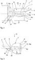
- Two bearing receptacles 15, 15a of the second housing part 4 have two bearings 16, 16a designed as needle bearings.
- the needle bearings 16, 16a support the cam 8. It can be seen particularly clearly that the second housing part 4 is adapted to the internal components, such as the cam 8 or the gear 7, so that the housing 1, of which the second housing part 4 is a component, builds as small as possible.
- the first housing part 3, the second housing part 4 and the third housing part 5 are designed as a housing 1 without further fixing elements. Furthermore, the first housing part 3 has a recess 32.
- the recess 32 is designed for a rotary lever, not shown, of the disc brake 38 (see Fig. Fig. 2 ) partially, the rotary lever (not shown) for actuating the disc brake 38 (see FIG. Fig. 2 ) is connected to the plunger 9.
- Fig. 3 shows the electromechanical brake actuator 2 without cam disk 8 (see Fig. Fig. 2 ) and the one for the storage of the cam 8 (s. Fig. 2 ) provided bearings 16, 16a.
- a largest radial diameter D3 of the second housing part 4 is 72.5 mm.
- a plunger receptacle 30 for positioning the plunger 9 is formed in the third housing part 5, the plunger receptacle 30 merging from the third housing part 5 into the second housing part 4, starting from the axial axis A2 of the third housing part 5.
- the plunger receptacle 30 merges into the third housing part 5 in a guide channel 21 for guiding and positioning the plunger 9.
- the guide channel 21 has an inner diameter D2 of 42 mm.
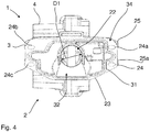
- Fig. 4 shows again the electromechanical brake actuator 2 according to the Figures 1 to 3 in a front view, starting from the first housing part 3.
- the first housing part 3 is from the flange side to connect the disc brake 38 (see FIG. Fig. 2 ) shown.
- the first flat contact surface 34 serves to support a plate of a two-plate die-casting machine during the forming process of the housing 1.
- An opening 22 of the first housing part 3 for receiving and actuating the plunger 9 can also be seen.
- An inner diameter D1 of the opening 22 corresponds to the inner diameter D2 of the guide channel 21 for the plunger 9.
- the groove 31 is made in sections on the outer edge region 23 of the first housing part 3, but closes the bores 24, 24a, 24b, 24c for fixing the electromechanical brake actuator 2 to the disc brake 38 (see Fig. Fig. 2 ) out. Furthermore, in Fig. 4 shown that the recess 32 for partially receiving a rotary lever, not shown, runs from the opening 22 in a funnel-shaped manner radially in the direction of the outer edge region 23 of the first housing part 3.
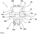
- Fig. 5 is once again the assembly opening 17 of the second housing part 4 of the in Figs. 1 to 4 shown electromechanical brake actuator 2 shown in detail.
- Fig. 6 shows an alternative embodiment of the electromechanical brake actuator 2.
- the alternative embodiment is, apart from the connection of the motor 37 (see FIG. Fig. 2 ) with the electromechanical brake actuator 2 according to the Figures 1 to 5 same component.
- the motor 37 is arranged on the region 27 of the electromechanical brake actuator 2 on the motor flange side, in the direction of the axial axis A of the second housing part 4, directly in the second housing part 4.
- a cylindrical partial area 36 of the second housing part 4 is axially extended in the direction of the area 27 of the electromechanical brake actuator 2 on the motor flange side in order to accommodate the motor 37.
- the bores 29, 29a, 29b, 29c of the second housing part 4 serve to receive and fix a cover, not shown, for closing the second housing part 4.
Landscapes
- Engineering & Computer Science (AREA)
- General Engineering & Computer Science (AREA)
- Mechanical Engineering (AREA)
- Braking Arrangements (AREA)
Abstract
Description
- Die Erfindung betrifft einen elektromechanischen Bremsaktuator mit einem Gehäuse für Scheibenbremsen von Fahrzeugen, insbesondere für Scheibenbremsen von Nutzfahrzeugen.
- Gehäuse dienen allgemein der Aufnahme und dem Schutz von Komponenten. Im Fahrzeugbereich müssen Gehäuse erhöhten Anforderungen, also hohe Steifigkeiten bei einem möglichst geringen Gewicht, genügen. Speziell im Bereich der Radaufhängung sind Gehäuseteile zudem intensiv Umweltbedingungen, wie zum Beispiel Steinschlägen, Staub, Schnee ausgesetzt. Weiterhin ist im Bereich der Radaufhängung für den Einbau von Komponenten generell nur ein geringes Platzangebot vorhanden. Aktuelle Entwicklungen zur Aktuierung von Scheibenbremsen gehen hin zu elektromechanischen Bremsaktuatoren. Elektromechanische Bremsaktuatoren weisen eine Vielzahl an Bauteilen auf, die u.a. gegen die beschriebenen Umwelteinflüsse geschützt werden müssen. Zudem wirken die Bauteile, wie ein Getriebe, eine Kurvenscheibe und ein Motor des elektromechanischen Bremsaktuators zusammen, weshalb die Bauteile fest in dem Gehäuse angeordnet oder gelagert sein müssen. Im Zuge von Leichtbauentwicklungen ist es eine zusätzliche Herausforderung, dass der elektromechanische Bremsaktuator so leicht wie möglich gebaut sein soll.
- Aufgabe der Erfindung ist es, einen elektromechanischen Bremsaktuator mit einem Gehäuse bereitzustellen, wobei das Gehäuse ein geringes Gewicht sowie eine hohe Steifigkeit aufweist und einfach in der Herstellung ist.
- Die Aufgabe wird dadurch gelöst, dass das Gehäuse des elektromechanischen Bremsaktuators ein Aluminium-Druckgussformteil ist. Aluminium weist gegenüber Stahl eine geringere Dichte auf, weshalb das Aluminium-Druckgussformteil leichter als ein Stahl-Gehäuse ist. Eingebaut in einem Fahrzeug, ermöglicht der Gewichtsunterschied des Aluminium-Druckgussformteils gegenüber einem Stahl-Gehäuse zusätzliche Kraftstoffeinsparungen während des Betriebs eines Fahrzeugs. Darüber hinaus ist Aluminium als Werkstoff gut verformbar, weshalb auch die Ausgestaltung detaillierte Ausprägungen, wie Versteifungsrippen oder Bohrlöcher, ohne größere Nachbearbeitung möglich sind. Zusätzlich ermöglicht der Werkstoff Aluminium die Herstellung des Aluminium-Druckgussformteils in einem Stück. Weitere Verbindungselemente, wie Schrauben, werden zur Herstellung des Aluminium-Druckgussformteils nicht benötigt.
- In einer bevorzugten Weiterbildung weist das erste Gehäuseteil des Aluminium-Druckgussformteils eine Anlagefläche für eine erste Platte der Zwei-Platten-Druckgießmaschine und das zweite Gehäuseteil des Aluminium-Druckgussformteils eine zweite Anlagefläche für eine zweite Platte einer Zwei-Platten-Druckgießmaschine auf.
Der Einsatz einer Zwei-Platten-Druckgießmaschine ist gegenüber einer Vier-Platten-Druckgießmaschine deutlich kostengünstiger und es sind an dem Gehäuse lediglich zwei ebene Flächen notwendig, an denen die Platten der Druckgießmaschine ansetzen und für die Umformung des Grundkörpers in ein Gehäuse den erforderlichen Druck erzeugen. Die erste Anlagefläche für die erste Platte ist die Flanschfläche zur Anbindung an eine Scheibenbremse. Die zweite Anlagefläche für die zweite Platte ist die Flanschfläche einer Montageöffnung zur Anbindung eines Deckels. Alle anderen Flächen des Gehäuses können damit nicht eben geformte Anbindungsflächen aufweisen oder mittels zusätzlicher Versteifungsrippen ausgestaltet werden. Darüber hinaus kann das Aluminium-Druckgussformteil in seiner Abmessung kleiner gebaut werden, da bereits vorhandene ebene Flächen als Anlageflächen für die Platten der Zwei-Platten-Druckgießmaschine verwendet werden und mittels zusätzlichem Material keine ebene Fläche an dem Aluminium-Druckgussformteil aufgebaut werden muss. - Das zweite Gehäuseteil weist in einer weiteren Ausgestaltung, axial bezogen auf eine axiale Achse des zweiten Gehäuseteils, einen Motorflansch zur Anbindung eines Motors auf Der Motorflansch ist kreisförmig ausgebildet und entspricht der Form eines elektrischen Motors. An der Außenwand des zweiten Gehäuseteils sind vier Bohrungen, insbesondere vier Gewindebohrungen, zur Anbindung eines Motors angeordnet. Die Bohrungen ermöglichen eine einfache Montage und Demontage des Motors. Das zweite Gehäuseteil kann aber auch in einer zweiten Ausführung, axial bezogen auf eine axiale Achse des zweiten Gehäuseteils, einen zylindrischen Teilbereich zur Aufnahme des Motors und einen Motorflansch zur Anbindung des Motors an eine Lagerstelle des zweiten Gehäuseteils aufweisen. Die Bohrungen sind in der zweiten Ausgestaltung des zweiten Gehäuseteils zur Aufnahme und Anbindung eines Deckels ausgelegt. Das zweite Gehäuseteil und der Deckel umschließen in der zweiten Ausführung den Motor vollständig.
- Zudem weist in einer weiteren Ausführung der Motorflansch, ausgehend von der axialen Achse des zweiten Gehäuseteils, mittig eine Lagerstelle auf. Ausgehend von der Lagerstelle sind radial in Richtung der Außenwand Verstärkungsrippen angeordnet. Besonders bevorzugt sind radial zwischen der Lagerstelle und der Außenwand Verstärkungsrippen angeordnet, wobei die Verstärkungsrippen mit einem gleichen Abstand voneinander angeordnet sind und damit für eine gleichmäßige Steifigkeit zwischen der Lagerstelle und der Außenwand sorgen. Darüber hinaus weist in einer weiterführenden Ausgestaltung das zweite Gehäuseteil an der Innenseite, axial zwischen dem Motorflansch und dem Getriebe, Lageraufnahmen zur Anordnung von Lagern auf, wobei die Lager dafür eingerichtet sind die Kurvenscheibe aufzunehmen. Konkret sind an der Innenseite des Gehäuses zwei Lageraufnahmen ausgebildet. Eine Lageraufnahme ist getriebeseitig angeordnet, also an der Innenseite des zweiten Gehäuseteils, an dem das Getriebe des elektromechanischen Bremsaktuators angeflanscht ist. Die zweite Lageraufnahme ist motorflanschseitig angeordnet, also an der Innenseite des zweiten Gehäuseteils, an dem der Motor des elektromechanischen Bremsaktuators angeflanscht ist. Die Lageraufnahmen sind bevorzugt für Nadellager ausgebildet.
- In einer weiteren vorteilhaften Ausgestaltung weist das zweite Gehäuseteil radial, entgegengesetzt der Richtung des ersten Gehäuseteils, zwischen dem Motorflansch und dem Getriebe, eine Montageöffnung für die Kurvenscheibe auf. Die Montageöffnung ist vorteilhaft kreisförmig ausgebildet und entspricht der Form einer länglichen Nut, die Montageöffnung geht also tangential in eine Gerade über. Es ist auch denkbar, dass die kreisförmige Montageöffnung tangential kreisrund fortgeführt wird, wobei die Montageöffnungsbreite gerade ausreicht, die Kurvenscheibe in schmalster Ausdehnung in die Montageöffnung einzuführen. Die Montageöffnung entspricht weitestgehend der Abmessung der Kurvenscheibe, damit die Kurvenscheibe zur Wartungszwecken in das zweite Gehäuseteil des elektromechanischen Bremsaktuators eingebaut oder ausgebaut werden kann.
- Zudem weist die Montageöffnung in einer weiteren Ausführung Ausnehmungen zur Aufnahme eines Bearbeitungswerkzeugs und Bohrungen zur Aufnahme eines Deckels auf. Der Deckel überdeckt die Montageöffnung vollständig und schützt den Elektromechanischen Bremsaktuator vor dem Eindringen ungewollter Umwelteinflüsse wie, Staub oder Geröll. Die Ausnehmungen und die Bohrungen sind radial an einem Außenrand der Montageöffnung eingebracht. Bevorzugt weist die Montageöffnung zwei gegenüberliegend und schräg versetzte Ausnehmungen auf, wobei die Ausnehmungen als Sacklochbohrungen ausgebildet sind. Zudem sind bevorzugt vier Bohrungen zur Aufnahme eines der Montageöffnung übergreifenden Deckels in dem äußeren Rand der Montageöffnung eingebracht. Die Bohrungen sind zur form- und kraftschlüssigen Fixierung des Deckels gleichmäßig versetzt angeordnet.
- In einer weiteren Ausgestaltung ist das dritte Gehäuseteil zylinderförmig ausgebildet und weist axial entlang einer axialen Achse des dritten Gehäuses einen Führungskanal zum Führen eines Stößels oder einer Spindel auf. Die zylinderförmige Ausgestaltung des dritten Gehäuseteils ist der Form des Stößels angepasst. Das heißt, dass das erste Gehäuseteil, das zweite Gehäuseteil und das dritte Gehäuseteil unterschiedliche und für den Nutzungszweck erforderliche Formen aufweisen. Gegenüber einem einheitlich großen Gehäuse sind die drei Gehäuseteile zusammengesetzt leichter, kompakter und benötigen weniger Material zur Herstellung des Gehäuses als ein einheitlich großes Gehäuse eines elektromechanischen Bremsaktuators. Darüber hinaus ist der Führungskanal in dem dritten Gehäuseteil in seiner Dimensionierung so ausgebildet, dass der Stößel gleitend in dem Führungskanal gelagert und geführt ist.
- Gemäß einer weiteren Ausbildung weist das erste Gehäuseteil mittig, bezogen auf eine axiale Achse des ersten Gehäuseteils, eine Öffnung zur Aufnahme und Betätigung des Stößels auf. Über die Öffnung kann der Stößel des elektromechanischen Bremsaktuators die Scheibenbremse mittels eines Drehhebels der Scheibenbremse zu spannen. Vorteilhaft entspricht in einer weiteren Ausführung ein innerer Durchmesser der Öffnung einem inneren Durchmesser des Führungskanals. Die Öffnung ist demnach als Teil des Führungskanals anzusehen. Eine kleiner als der Stößel ausgebildete Öffnung würde während der Betätigung des elektromechanischen Bremsaktuators zu einem Verklemmen des Stößels führen. Eine zu große Öffnung, also eine Öffnung die im Durchmesser größer ist als der Führungskanal, führt dazu, dass der Stößel axial in Richtung des Drehhebels der Scheibenbremse nicht richtig geführt ist und es zu einem Verklemmen oder sogar zu einem Herausfallen des Stößels aus dem Führungskanal kommen kann.
- In einer weiteren Ausbildung weist das erste Gehäuseteil axial an dem ersten äußeren Randbereich des ersten Gehäuseteils Bohrungen zur Anbindung an eine Scheibenbremse auf. Der erste Gehäuseteil entspricht in seiner Größe und in seiner Form einer Öffnung zur Aktuierung der Scheibenbremse. Bevorzugt mittels vier Bohrungen in dem ersten Gehäuseteil, in denen Schrauben oder Nieten eingebracht werden, wird der elektromechanische Bremsaktuator an die Scheibenbremse formschlüssig und kraftschlüssig fixiert. Zusätzlich weist das erste Gehäuseteil radial zwischen den Bohrungen Streben auf, die als Verstärkungsrippen ausgebildet sind.
- In einer letzten Ausführung weist das erste Gehäuseteil axial, entgegengesetzt der Richtung des dritten Gehäuseteils, eine Nut zur Aufnahme einer Dichtung auf. Konkret ist die Nut in dem ersten Gehäuseteil an der Flanschseite zur Anbindung an die Scheibenbremse eingelassen. In die Nut ist eine Dichtung eingelassen, die die Verbindung zwischen der Scheibenbremse und dem Gehäuse mit dem ersten Gehäuseteil gegen Einwirkungen aus der Umwelt abdichtet. Die Nut ist unterbrechungsfrei entlang der Flanschseite des ersten Gehäuseteils eingebracht. Die Bohrungen des ersten Gehäuseteils befinden sich außerhalb der abzudichtenden Fläche der Flanschseite des ersten Gehäuseteils.
- Nachfolgend werden ausgewählte Ausführungsbeispiele der Erfindung anhand der beigefügten Figuren erläutert.
- Es zeigt:
-
Fig. 1 einen elektromechanischen Bremsaktuator aus einer seitlich gedrehten Ansicht ohne Motor und Kurvenscheibe, -
Fig. 2 eine geschnittene Ansicht eines elektromechanischen Bremsaktuators, -
Fig. 3 eine seitlich geschnittene Ansicht eines elektromechanischen Bremsaktuators, -
Fig. 4 eine Vorderansicht eins elektromechanischen Bremsaktuators ausgehend von einem ersten Gehäuseteil, -
Fig. 5 eine Draufsicht auf einen elektromechanischen Bremsaktuators, ausgehend von dem zweiten Gehäuseteil, -
Fig. 6 einen elektromechanischen Bremsaktuator in einer alternativen Ausführungsform aus einer seitlich gedrehten Ansicht ohne Motor und Kurvenscheibe. -
Fig. 1 zeigt einen elektromechanischen Bremsaktuator 2 mit einen inFig. 2 gezeigten Motor 37 und einer Kurvenscheibe 8 (s.Fig.2 ). Der elektromechanische Bremsaktuator 2 ist von einer Außenseite 10 eines Gehäuses 1 gezeigt. Das Gehäuse 1 setzt sich aus drei Gehäuseteilen zusammen. Ein erstes Gehäuseteil 3 ist plattenförmig als Flansch zur Anbindung an eine inFig. 2 gezeigte Scheibenbremse 38 ausgebildet. Das erste Gehäuseteil 3 weist, ausgehend von einer axialen Achse A3 des ersten Gehäuseteils 3, vier axiale Bohrungen 24, 24a, 24b, 24c auf. Die Bohrungen 24, 24a, 24b, 24c sind an einem äußeren Randbereich 23 des ersten Gehäuseteils 3 angeordnet und dienen der Fixierung an eine inFig. 2 gezeigte Scheibenbremse 38 mittels nicht gezeigter Schrauben. Zwischen den sich gegenüberliegenden Bohrungen 24, 24c und den sich gegenüberliegenden Bohrungen 24a, 24b sind Versteifungsrippen 25, 25a angeordnet. Mittig am ersten Gehäuseteil 3 ist ein drittes Gehäuseteil 5 angeordnet. Das dritte Gehäuseteil 5 ist als Zylinder geformt und verbindet das erste Gehäuseteil 3 mit einem zweiten Gehäuseteil 4. Ausgehend von einer Bezugebene E des ersten Gehäuseteils 3, steht das dritte Gehäuseteil 5 entlang einer axialen Achse A2 des dritten Gehäuseteils 5 schräg von der Bezugebene E ab. Ausgehend von einer axialen Achse A des zweiten Gehäuseteils 4 ist das zweite Gehäuseteil 4 zylinderförmig ausgebildet, wobei das zweite Gehäuseteil 4 einen antriebsseitigen Bereich 26 und einen motorflanschseitigen Bereich 27 aufweist. Der motorflanschseitige Bereich 27 des zweiten Gehäuseteils 4 weist einen Motorflansch 11 zum Anbinden eines Motors 37 (s.Fig. 2 ) auf. Das Drehmoment des Motors 37 wird als Reaktionsmoment über den Motorflansch 11 abgestützt. Zentral und axial im Motorflansch 11 ist eine Lagerstelle 12 zur Abstützung der resultierenden Axialkräfte und/oder Betätigungskräfte eines Stößels 9 auf eine in dem zweiten Bremsgehäuseteil 4 angeordnete Kurvenscheibe 8 angeordnet. (s.Fig. 2 ), Von der Lagerstelle 12 ausgehend und radial verlaufend in Richtung eines umlaufenden Randbereichs 28 des Motorflansches 11, sind Verstärkungsrippen 13 angeordnet. Zur Anbindung des Motors 37 an den Motorflansch 11, weist der umlaufende Randbereich 28 des Motorflansches 11 vier Bohrungen 29, 29a, 29b, 29c) auf. Zwischen dem Motorflansch 11 und dem antriebsseitigen Bereich 26 elektromechanischen Bremsaktuators 2 des zweiten Gehäuseteils 4 ist radial eine Montageöffnung 17 angeordnet. Die Montageöffnung 17 weist einen Flanschbereich 33 zur Anordnung eines nicht gezeigten Deckels auf. Zusätzlich weist der Flanschbereich 33 eine zweite ebene Anlagefläche 34 auf, an der sich während des Umformprozesses des Gehäuses 1 eine Platte einer Zwei-Platten-Druckgießmaschine abstützt. Eine erste ebene Anlagefläche 34 ist inFig. 4 gezeigt. Die Platte und die Zwei-Platten-Druckgießmaschine sind nicht gezeigt. Über Bohrungen 19, 19a, 19b, 19c der Montageöffnung 17 ist der nicht gezeigte Deckel mittels Schrauben kraftschlüssig und formschlüssig verbunden. Zwei sich schräg gegenüberliegende Ausnehmungen 18, 18a am Flanschbereich 33 der Montageöffnung 17 vereinfachen eine Bearbeitung des Gehäuses 1 während der Herstellung. -
Fig. 2 zeigt eine Teilansicht des inFig. 1 gezeigten elektromechanischen Bremsaktuator 2. Zusätzlich zeigtFig. 2 eine Innenseite 14 des Gehäuses 1 mit einem Antrieb 6. Gut zu sehen ist in dem zweiten Gehäuseteil 4, in dem antriebsseitigen Bereich 26 , ein Getriebe 7 zur Anpassung der Drehzahlen des Motors 37 auf die Kurvenscheibe 8. Zwei Lageraufnahmen 15, 15a des zweiten Gehäuseteils 4 weisen zwei als Nadellager ausgebildete Lager 16, 16a auf. Die Nadellager 16, 16a lagern die Kurvenscheibe 8. Besonders gut zu sehen ist, dass das zweiten Gehäuseteil 4 entsprechend den innenliegenden Komponenten, wie der Kurvenscheibe 8 oder dem Getriebe 7 angepasst ist, sodass das Gehäuse 1, deren Bestandteil das zweite Gehäuseteil 4 ist, möglichst klein baut. Darüber hinaus istFig. 2 zu entnehmen, dass das erste Gehäuseteil 3, das zweite Gehäuseteil 4 und das dritte Gehäuseteil 5 ohne weitere Fixierungselemente als ein Gehäuse 1 ausgebildet ist. Weiterhin weist das erste Gehäuseteil 3 eine Aussparung 32 auf. Die Aussparung 32 ist dafür ausgelegt einen nicht gezeigten Drehhebel der Scheibenbremse 38 (s.Fig. 2 ) teilweise aufzunehmen, wobei der nicht gezeigte Drehhebel zur Aktuierung der Scheibenbremse 38 (s.Fig. 2 ) mit dem Stößel 9 in Verbindung steht. -
Fig. 3 zeigt den elektromechanischen Bremsaktuator 2 ohne Kurvenscheibe 8 (s.Fig. 2 ) und die für die Lagerung der Kurvenscheibe 8 (s.Fig. 2 ) vorgesehenen Lager 16, 16a. Das heißt, die zentral im zweiten Gehäuseteil 4 angeordneten Lageraufnahmen 15, 15a sind gut sichtbar. Ein größter radialer Durchmesser D3 des zweiten Gehäuseteils 4 beträgt 72,5 mm. Im dritten Gehäuseteil 5 ist eine Stößelaufnahme 30 zur Positionierung des Stößels 9 ausgeformt, wobei die Stößelaufnahme 30, ausgehend von der axialen Achse A2 des dritten Gehäuseteils 5, von dem dritten Gehäusteil 5 in das zweite Gehäuseteil 4 übergeht. Die Stößelaufnahme 30 geht in dem dritten Gehäuseteil 5 in einem Führungskanal 21 zum Führen und Positionierung des Stößels 9 über. Der Führungskanal 21weist einen inneren Durchmesser D2 von 42 mm auf. -
Fig. 4 zeigt noch einmal den elektromechanischen Bremsaktuator 2 nach denFiguren 1 bis 3 in einer Frontalansicht, ausgehend von dem ersten Gehäuseteil 3. Das erste Gehäuseteil 3 ist von der Flanschseite zur Anbindung der Scheibenbremse 38 (s.Fig. 2 ) gezeigt. Die erste ebene Anlagefläche 34 dient während des Umformprozesses des Gehäuses 1 dem Abstützen einer Platte einer Zwei-Platten-Druckgießmaschine. Zusätzlich erkennbar ist eine Öffnung 22 des ersten Gehäuseteils 3 zur Aufnahme und Aktuierung des Stößels 9. Ein innerer Durchmesser D1 der Öffnung 22 entspricht dem inneren Durchmesser D2 des Führungskanals 21 für den Stößel 9. Zur Abdichtung der Öffnung 22 gegen ein Eindringen von Verschmutzungen, weist das erste Gehäuseteil 3 flanschseitig eine umlaufende Nut 31 zur Aufnahme einer nicht gezeigten Dichtung auf. Die Nut 31 ist abschnittsweise an dem äußeren Randbereich 23 des ersten Gehäuseteils 3 eingebracht, schließt aber die Bohrungen 24, 24a, 24b, 24c zur Fixierung des elektromechanischen Bremsaktuators 2 an die Scheibenbremse 38 (s.Fig. 2 ) aus. Des Weiteren ist inFig. 4 gezeigt, dass die Aussparung 32 zur teilweisen Aufnahme eines nicht gezeigten Drehhebels, von der Öffnung 22, trichterförmig radial in Richtung des äußeren Randbereichs 23 des ersten Gehäuseteils 3 verläuft. - In
Fig.5 ist noch einmal die Montageöffnung 17 des zweiten Gehäuseteils 4 des inFig. 1 bis 4 gezeigten elektromechanischen Bremsaktuators 2 im Detail gezeigt. -
Fig. 6 zeigt eine alternative Ausführungsform des elektromechanischen Bremsaktuators 2. Die alternative Ausführungsform ist bis auf die Anbindung des Motors 37 (s.Fig. 2 ) mit dem elektromechanischen Bremsaktuator 2 nach denFiguren 1 bis 5 bauteilgleich. Der Motor 37 ist am motorflanschseitigen Bereich 27 des elektromechanischen Bremsaktuators 2, in Richtung der axialen Achse A des zweiten Gehäuseteils 4, direkt im zweiten Gehäuseteil 4 angeordnet. Ein zylindrischer Teilbereich 36 des zweiten Gehäuseteils 4 ist zur Aufnahme des Motors 37, in Richtung des motorflanschseitigen Bereichs 27 des elektromechanischen Bremsaktuators 2, axial verlängert. Die Bohrungen 29, 29a, 29b, 29c des zweiten Gehäuseteils 4 dienen der Aufnahme und Fixierung eines nicht gezeigten Deckels zum Verschließen des zweiten Gehäuseteils 4. -
- 1
- Gehäuse
- 2
- Elektromechanischer Bremsaktuator
- 3
- erstes Gehäuseteil
- 4
- zweites Gehäuseteil
- 5
- drittes Gehäuseteil
- 6
- Antrieb
- 7
- Getriebe des Antriebs 6
- 8
- Kurvenscheibe des Antriebs 6
- 9
- Stößel
- 10
- Außenseite des Gehäuses 1
- 11
- Motorflansch
- 12
- Lagerstelle
- 13
- Verstärkungsrippen
- 14
- Innenseite des Gehäuses 1
- 15, 15a
- Lageraufnahmen
- 16, 16a
- Lager
- 17
- Montageöffnung
- 18, 18a
- Ausnehmungen der Montageöffnung 17
- 19 bis 19c
- Bohrungen der Montageöffnung 17
- 21
- Führungskanal
- 22
- Öffnung des ersten Gehäuseteils 3
- 23
- äußerer Randbereich des ersten Gehäuseteils 3
- 24 bis 24c
- Bohrungen des ersten Gehäuseteils 3
- 25, 25a
- Versteifungsrippen
- 26
- antriebsseitiger Bereich des zweiten Gehäuseteils 4 des elektromechanischen Bremsaktuators 2
- 27
- motorflanschseitiger Bereich des Elektromechanischen Bremsaktuators 2
- 28
- umlaufender Randbereich des Motorflansches 11
- 29 bis 29c
- Bohrungen des zweiten Gehäuseteils 4
- 30
- Stößelaufnahme
- 31
- Nut des ersten Gehäuseteils 3
- 32
- Aussparung
- 33
- Flanschbereich der Montageöffnung 17
- 34
- erste ebene Anlagefläche
- 34a
- zweite ebene Anlagefläche
- 36
- zylindrischer Teilbereich des zweiten Gehäuseteils 4
- 37
- Motor
- 38
- Scheibenbremse
- A
- axiale Achse des zweiten Gehäuseteils 4
- A2
- axiale Achse des dritten Gehäuseteils 5
- A3
- axiale Achse des ersten Gehäuseteils 3
- D1
- innerer Durchmesser der Öffnung 22 des ersten Gehäuseteils 3
- D2
- innerer Durchmesser des Führungskanals 21
- D3
- größter radialer Durchmesser des zweiten Gehäuseteils 4
- E
- Bezugebene
Claims (12)
- Elektromechanischer Bremsaktuator (2) mit einem Gehäuse (1) aufweisend, ein als Gehäuseflansch ausgebildetes erstes Gehäuseteil (3) zur Anbindung des elektromechanischen Bremsaktuators (2) an eine Scheibenbremse (38), ein zweites Gehäuseteil (4) zur Aufnahme eines Antriebs (6), und ein zwischen dem ersten Gehäuseteil (3) und dem zweiten Gehäuseteil (4) angeordnetes und mit dem ersten Gehäuseteil (3) und dem zweiten Gehäuseteil (4) verbundenes drittes, Gehäuseteil (5), und wobei der elektromechanische Bremsaktuator (2) Mittel, umfassend einen Motor (37), ein Getriebe (7), einen Stößel (9) oder eine Spindel, zum aktuieren einer Scheibenbremse (38) aufweist, dadurch gekennzeichnet, dass das Gehäuse (1) ein Aluminium-Druckgussformteil ist.
- Elektromechanischer Bremsaktuator (2) nach Anspruch 1, dadurch gekennzeichnet, dass das erste Gehäuseteil (3) eine ebene erste Anlagefläche (34) aufweist und das zweite Gehäuseteil (4) eine ebene zweite Anlagefläche (34a) aufweist, wobei die ebenen Anlageflächen (34, 34a) dazu ausgebildet sind, während des Umformprozesses des Gehäuses (1) Platten einer Zwei-Platten-Druckgießmaschine aufzunehmen.
- Elektromechanischer Bremsaktuator (2) nach Anspruch 1 oder 2, dadurch gekennzeichnet, dass an einer Außenseite (10) des Gehäuses (1) das zweite Gehäuseteil (4), einen Motorflansch (11) zur Anbindung des Motors (37) aufweist oder dass das das zweite Gehäuseteil (4) einen zylindrischen Teilbereich (36) zur Aufnahme eines Motors (37) und einen Motorflansch (11) zur Anbindung eines Motors (37) aufweist.
- Elektromechanischer Bremsaktuator (2) nach Anspruch 3, dadurch gekennzeichnet, dass der Motorflansch (11), ausgehend von einer axialen Achse (A) des zweiten Gehäuseteils (4), mittig eine Lagerstelle (12) aufweist und der Motorflansch (11), ausgehend von der Lagerstelle (12), in Richtung der Außenseite (10) des Gehäuses, (1) radial verlaufende Verstärkungsrippen (13) aufweist.
- Elektromechanischer Bremsaktuator (2) nach Anspruch 3, dadurch gekennzeichnet, dass das zweite Gehäuseteil (4) an einer Innenseite (14) des Gehäuses (1), axial zwischen dem Motorflansch (11) und dem Getriebe (7) Lageraufnahmen (15, 15a) zur Anordnung von Lagern (16, 16a) aufweist, wobei die Lager (16, 16a) dafür eingerichtet sind, eine Kurvenscheibe (8) aufzunehmen.
- Elektromechanischer Bremsaktuator (2) nach Anspruch 5, dadurch gekennzeichnet, dass das zweite Gehäuseteil (4) radial, entgegengesetzt der Richtung des ersten Gehäuseteils (3), zwischen dem Motorflansch (11) und dem Getriebe (7), eine Montageöffnung (17) für die Kurvenscheibe (8) aufweist.
- Elektromechanischer Bremsaktuator (2) nach Anspruch 6, dadurch gekennzeichnet, dass die Montageöffnung (17) Ausnehmungen (18, 18a) zur Aufnahme eines Bearbeitungswerkzeugs aufweist und das die Montageöffnung (17) Bohrungen (19, 19a, 19b, 19c) zur Aufnahme eines Deckels aufweist.
- Elektromechanischer Bremsaktuator (2) nach einem der vorangegangenen Ansprüche, dadurch gekennzeichnet, dass das dritte Gehäuseteil (5) zylinderförmig ausgebildet ist und axial entlang einer axialen Achse (A2) des dritten Gehäuses (5) einen Führungskanal (21) zum Führen des Stößels (9) aufweist.
- Elektromechanischer Bremsaktuator (2) nach Anspruch 8, dadurch gekennzeichnet, dass das erste Gehäuseteil (3) mittig, bezogen auf eine axiale Achse (A3) des ersten Gehäuseteils (3), eine Öffnung (22) zur Aufnahme und Betätigung des Stößels (9) aufweist.
- Elektromechanischer Bremsaktuator (2) nach Anspruch 9, dadurch gekennzeichnet, dass ein innerer Durchmesser (D1) der Öffnung (22) einem inneren Durchmesser (D2) des Führungskanals (21) entspricht.
- Elektromechanischer Bremsaktuator (2) nach einem der vorangegangenen Ansprüche, dadurch gekennzeichnet, dass das erste Gehäuseteil (3) axial an dem äußeren Randbereich (23) des ersten Gehäuseteils (3) Bohrungen (24, 24a, 24b, 24c) zur Anbindung an die Scheibenbremse (38) aufweist.
- Elektromechanischer Bremsaktuator (2) nach einem der vorangegangenen Ansprüche, dadurch gekennzeichnet, dass das erste Gehäuseteil (3) axial, entgegengesetzt der Richtung des dritten Gehäuseteils (5) eine Nut (31) zur Aufnahme einer Dichtung aufweist.
Priority Applications (3)
| Application Number | Priority Date | Filing Date | Title |
|---|---|---|---|
| EP19193160.9A EP3783243B1 (de) | 2019-08-22 | 2019-08-22 | Elektromechanischer bremsaktuator für eine scheibenbremse |
| US16/998,013 US11566674B2 (en) | 2019-08-22 | 2020-08-20 | Electromechanical brake actuator for disc brakes |
| CN202010847414.3A CN112413013B (zh) | 2019-08-22 | 2020-08-21 | 用于车辆的盘式制动器的机电制动执行器 |
Applications Claiming Priority (1)
| Application Number | Priority Date | Filing Date | Title |
|---|---|---|---|
| EP19193160.9A EP3783243B1 (de) | 2019-08-22 | 2019-08-22 | Elektromechanischer bremsaktuator für eine scheibenbremse |
Publications (2)
| Publication Number | Publication Date |
|---|---|
| EP3783243A1 true EP3783243A1 (de) | 2021-02-24 |
| EP3783243B1 EP3783243B1 (de) | 2022-12-28 |
Family
ID=67770350
Family Applications (1)
| Application Number | Title | Priority Date | Filing Date |
|---|---|---|---|
| EP19193160.9A Active EP3783243B1 (de) | 2019-08-22 | 2019-08-22 | Elektromechanischer bremsaktuator für eine scheibenbremse |
Country Status (3)
| Country | Link |
|---|---|
| US (1) | US11566674B2 (de) |
| EP (1) | EP3783243B1 (de) |
| CN (1) | CN112413013B (de) |
Families Citing this family (1)
| Publication number | Priority date | Publication date | Assignee | Title |
|---|---|---|---|---|
| CN119116911B (zh) * | 2024-11-12 | 2025-02-11 | 万向钱潮股份公司 | 一种执行器壳体组件及驻车执行器 |
Citations (2)
| Publication number | Priority date | Publication date | Assignee | Title |
|---|---|---|---|---|
| EP2174037A1 (de) * | 2007-07-30 | 2010-04-14 | Freni Brembo S.p.A. | Elektrische feststellbremse |
| EP2815150A1 (de) * | 2012-02-15 | 2014-12-24 | Freni Brembo S.p.A. | Elektrische bremse, insbesondere feststellbremse |
Family Cites Families (17)
| Publication number | Priority date | Publication date | Assignee | Title |
|---|---|---|---|---|
| BR9811123B1 (pt) * | 1997-08-25 | 2011-04-19 | freio mecánico, ativável eletromagneticamente, para um motor elétrico. | |
| DE102006016543A1 (de) * | 2006-04-07 | 2007-10-18 | Lucas Automotive Gmbh | Hydraulisch betätigbare Fahrzeugbremse mit Verriegelung |
| DE102008004806A1 (de) * | 2008-01-17 | 2009-07-30 | Knorr-Bremse Systeme für Nutzfahrzeuge GmbH | Pneumatisch betätigte Scheibenbremse mit Betätigungsstößel |
| DE102008034300A1 (de) * | 2008-07-23 | 2010-01-28 | Lucas Automotive Gmbh | Fahrzeugscheibenbremse |
| JP5847561B2 (ja) * | 2011-11-29 | 2016-01-27 | 日立オートモティブシステムズ株式会社 | ディスクブレーキ |
| GB201211722D0 (en) * | 2012-07-02 | 2012-08-15 | Meritor Heavy Vehicle Braking | A disc brake |
| KR101321719B1 (ko) * | 2013-04-17 | 2013-10-28 | 계양전기 주식회사 | 전자식 파킹 브레이크 액추에이터 조립체 |
| DE102013008155A1 (de) * | 2013-05-13 | 2014-11-13 | Wabco Europe Bvba | Sattelscheibenbremse eines Fahrzeugs, insbesondere eines Nutzfahrzeugs, und Niederhalteeinrichtung einer solchen Bremse |
| EP2921358B1 (de) * | 2014-03-21 | 2019-05-01 | IMS Gear SE & Co. KGaA | Aktuatoranordnung |
| CN106415049B (zh) * | 2014-04-01 | 2019-07-16 | 福乐尼·乐姆宝公开有限公司 | 制动齿轮马达组 |
| CN105932811B (zh) * | 2015-02-27 | 2019-12-10 | 博泽沃尔兹堡汽车零部件有限公司 | 电机结构组件 |
| KR102446044B1 (ko) * | 2015-05-12 | 2022-09-23 | 주식회사 만도 | 전동식 디스크 브레이크 |
| DE102017004436A1 (de) * | 2017-05-09 | 2018-11-15 | Wabco Europe Bvba | Elektromechanischer Bremsenaktuator |
| CN109281961B (zh) * | 2017-07-21 | 2021-03-12 | 英国美瑞特重型车制动系统有限公司 | 盘式制动器 |
| JP7308070B2 (ja) * | 2019-04-26 | 2023-07-13 | ナブテスコ株式会社 | ブレーキ装置およびブレーキ制御システム |
| EP3783242B1 (de) * | 2019-08-22 | 2022-12-28 | ZF CV Systems Global GmbH | Scheibenbremse für fahrzeuge, insbesondere für nutzahrzeuge, mit einem elektromechanischen aktuator |
| EP3805059B1 (de) * | 2019-10-07 | 2022-12-28 | ZF CV Systems Global GmbH | Scheibenbremse mit einem elektromechanischen aktuator, insbesondere einem elektromechanischen parkbremsaktuator |
-
2019
- 2019-08-22 EP EP19193160.9A patent/EP3783243B1/de active Active
-
2020
- 2020-08-20 US US16/998,013 patent/US11566674B2/en active Active
- 2020-08-21 CN CN202010847414.3A patent/CN112413013B/zh active Active
Patent Citations (2)
| Publication number | Priority date | Publication date | Assignee | Title |
|---|---|---|---|---|
| EP2174037A1 (de) * | 2007-07-30 | 2010-04-14 | Freni Brembo S.p.A. | Elektrische feststellbremse |
| EP2815150A1 (de) * | 2012-02-15 | 2014-12-24 | Freni Brembo S.p.A. | Elektrische bremse, insbesondere feststellbremse |
Also Published As
| Publication number | Publication date |
|---|---|
| US11566674B2 (en) | 2023-01-31 |
| CN112413013B (zh) | 2022-07-12 |
| CN112413013A (zh) | 2021-02-26 |
| US20210054894A1 (en) | 2021-02-25 |
| EP3783243B1 (de) | 2022-12-28 |
Similar Documents
| Publication | Publication Date | Title |
|---|---|---|
| EP2753843B1 (de) | Kolben für einen bremssattel einer scheibenbremse | |
| DE102022004575B3 (de) | Elektrischer Radnabenantrieb für ein Kraftfahrzeug | |
| EP2611625B1 (de) | Radbaugruppe für kraftfahrzeuge | |
| EP3586041B1 (de) | Antrieb, umfassend einen elektromotor und ein getriebe, und verfahren zum herstellen eines antriebs | |
| EP3783242B1 (de) | Scheibenbremse für fahrzeuge, insbesondere für nutzahrzeuge, mit einem elektromechanischen aktuator | |
| EP2611626A1 (de) | Radbaugruppe für kraftfahrzeug | |
| DE202005005620U1 (de) | Pumpenaggregat | |
| DE102018215734A1 (de) | Baukastensystem zum Herstellen von unterschiedlichen Bauvarianten eines Rotors für eine elektrische Maschine eines Kraftfahrzeugs sowie elektrische Maschine für ein Kraftfahrzeug | |
| WO2013143980A1 (de) | Scheibenbremse, insbesondere für ein nutzfahrzeug | |
| DE102009014879A1 (de) | Radbaugruppe für ein Kraftfahrzeug | |
| DE102004045218B4 (de) | Bremsenträger und scheibenbremse mit einem solchen bremsenträger | |
| DE102021108127B4 (de) | Elektrische Maschine, elektrische Maschinenanordnung und Verfahren zur Montage einer elektrischen Maschine | |
| WO2020187973A1 (de) | Elektrischer antrieb mit einer elektrischen maschine und mit einer leistungselektronik | |
| EP3783243B1 (de) | Elektromechanischer bremsaktuator für eine scheibenbremse | |
| EP3302754A1 (de) | TELLERSEPARATOR MIT GESCHWEIßTEM KUNSTSTOFFGEHÄUSE | |
| DE102004001495A1 (de) | Bremszange und Verfahren zur Herstellung eines Gehäuses einer Bremszange | |
| DE102017200338A1 (de) | Radlager für ein Kraftfahrzeug | |
| DE102020100291A1 (de) | Radlagervorrichtung und Fahrzeug mit einer Radlagervorrichtung | |
| DE102016216717A1 (de) | Getriebemotorantrieb mit im Getriebegehäuse integrierter Lagerbrille | |
| DE102008015686B4 (de) | Antrieb und Vorrichtung | |
| DE102023001258A1 (de) | Elektrischer Radnabenantrieb für ein Kraftfahrzeug, insbesondere für einen Kraftwagen | |
| WO2011131403A1 (de) | Getriebebremse | |
| EP3797228B1 (de) | Richtungspfeil am bremsenträger | |
| EP2933522B1 (de) | Sattelscheibenbremse und betätigungseinrichtung einer solchen sattelscheibenbremse | |
| DE102016100137A1 (de) | Scheibenbremse für ein Nutzfahrzeug |
Legal Events
| Date | Code | Title | Description |
|---|---|---|---|
| PUAI | Public reference made under article 153(3) epc to a published international application that has entered the european phase |
Free format text: ORIGINAL CODE: 0009012 |
|
| STAA | Information on the status of an ep patent application or granted ep patent |
Free format text: STATUS: THE APPLICATION HAS BEEN PUBLISHED |
|
| AK | Designated contracting states |
Kind code of ref document: A1 Designated state(s): AL AT BE BG CH CY CZ DE DK EE ES FI FR GB GR HR HU IE IS IT LI LT LU LV MC MK MT NL NO PL PT RO RS SE SI SK SM TR |
|
| AX | Request for extension of the european patent |
Extension state: BA ME |
|
| RAP3 | Party data changed (applicant data changed or rights of an application transferred) |
Owner name: ZF CV SYSTEMS GLOBAL GMBH |
|
| STAA | Information on the status of an ep patent application or granted ep patent |
Free format text: STATUS: REQUEST FOR EXAMINATION WAS MADE |
|
| 17P | Request for examination filed |
Effective date: 20210824 |
|
| RBV | Designated contracting states (corrected) |
Designated state(s): AL AT BE BG CH CY CZ DE DK EE ES FI FR GB GR HR HU IE IS IT LI LT LU LV MC MK MT NL NO PL PT RO RS SE SI SK SM TR |
|
| RIC1 | Information provided on ipc code assigned before grant |
Ipc: F16D 121/24 20120101ALN20220801BHEP Ipc: F16D 55/2255 20060101ALN20220801BHEP Ipc: F16D 65/18 20060101AFI20220801BHEP |
|
| GRAP | Despatch of communication of intention to grant a patent |
Free format text: ORIGINAL CODE: EPIDOSNIGR1 |
|
| STAA | Information on the status of an ep patent application or granted ep patent |
Free format text: STATUS: GRANT OF PATENT IS INTENDED |
|
| RIC1 | Information provided on ipc code assigned before grant |
Ipc: F16D 121/24 20120101ALN20220907BHEP Ipc: F16D 55/2255 20060101ALN20220907BHEP Ipc: F16D 65/18 20060101AFI20220907BHEP |
|
| INTG | Intention to grant announced |
Effective date: 20220930 |
|
| GRAS | Grant fee paid |
Free format text: ORIGINAL CODE: EPIDOSNIGR3 |
|
| GRAA | (expected) grant |
Free format text: ORIGINAL CODE: 0009210 |
|
| STAA | Information on the status of an ep patent application or granted ep patent |
Free format text: STATUS: THE PATENT HAS BEEN GRANTED |
|
| AK | Designated contracting states |
Kind code of ref document: B1 Designated state(s): AL AT BE BG CH CY CZ DE DK EE ES FI FR GB GR HR HU IE IS IT LI LT LU LV MC MK MT NL NO PL PT RO RS SE SI SK SM TR |
|
| REG | Reference to a national code |
Ref country code: GB Ref legal event code: FG4D Free format text: NOT ENGLISH |
|
| REG | Reference to a national code |
Ref country code: CH Ref legal event code: EP |
|
| REG | Reference to a national code |
Ref country code: DE Ref legal event code: R096 Ref document number: 502019006615 Country of ref document: DE |
|
| REG | Reference to a national code |
Ref country code: AT Ref legal event code: REF Ref document number: 1540684 Country of ref document: AT Kind code of ref document: T Effective date: 20230115 |
|
| REG | Reference to a national code |
Ref country code: IE Ref legal event code: FG4D Free format text: LANGUAGE OF EP DOCUMENT: GERMAN |
|
| REG | Reference to a national code |
Ref country code: LT Ref legal event code: MG9D |
|
| PG25 | Lapsed in a contracting state [announced via postgrant information from national office to epo] |
Ref country code: SE Free format text: LAPSE BECAUSE OF FAILURE TO SUBMIT A TRANSLATION OF THE DESCRIPTION OR TO PAY THE FEE WITHIN THE PRESCRIBED TIME-LIMIT Effective date: 20221228 Ref country code: NO Free format text: LAPSE BECAUSE OF FAILURE TO SUBMIT A TRANSLATION OF THE DESCRIPTION OR TO PAY THE FEE WITHIN THE PRESCRIBED TIME-LIMIT Effective date: 20230328 Ref country code: LT Free format text: LAPSE BECAUSE OF FAILURE TO SUBMIT A TRANSLATION OF THE DESCRIPTION OR TO PAY THE FEE WITHIN THE PRESCRIBED TIME-LIMIT Effective date: 20221228 Ref country code: FI Free format text: LAPSE BECAUSE OF FAILURE TO SUBMIT A TRANSLATION OF THE DESCRIPTION OR TO PAY THE FEE WITHIN THE PRESCRIBED TIME-LIMIT Effective date: 20221228 |
|
| REG | Reference to a national code |
Ref country code: NL Ref legal event code: MP Effective date: 20221228 |
|
| PG25 | Lapsed in a contracting state [announced via postgrant information from national office to epo] |
Ref country code: RS Free format text: LAPSE BECAUSE OF FAILURE TO SUBMIT A TRANSLATION OF THE DESCRIPTION OR TO PAY THE FEE WITHIN THE PRESCRIBED TIME-LIMIT Effective date: 20221228 Ref country code: LV Free format text: LAPSE BECAUSE OF FAILURE TO SUBMIT A TRANSLATION OF THE DESCRIPTION OR TO PAY THE FEE WITHIN THE PRESCRIBED TIME-LIMIT Effective date: 20221228 Ref country code: HR Free format text: LAPSE BECAUSE OF FAILURE TO SUBMIT A TRANSLATION OF THE DESCRIPTION OR TO PAY THE FEE WITHIN THE PRESCRIBED TIME-LIMIT Effective date: 20221228 Ref country code: GR Free format text: LAPSE BECAUSE OF FAILURE TO SUBMIT A TRANSLATION OF THE DESCRIPTION OR TO PAY THE FEE WITHIN THE PRESCRIBED TIME-LIMIT Effective date: 20230329 |
|
| PG25 | Lapsed in a contracting state [announced via postgrant information from national office to epo] |
Ref country code: NL Free format text: LAPSE BECAUSE OF FAILURE TO SUBMIT A TRANSLATION OF THE DESCRIPTION OR TO PAY THE FEE WITHIN THE PRESCRIBED TIME-LIMIT Effective date: 20221228 |
|
| P01 | Opt-out of the competence of the unified patent court (upc) registered |
Effective date: 20230528 |
|
| PG25 | Lapsed in a contracting state [announced via postgrant information from national office to epo] |
Ref country code: SM Free format text: LAPSE BECAUSE OF FAILURE TO SUBMIT A TRANSLATION OF THE DESCRIPTION OR TO PAY THE FEE WITHIN THE PRESCRIBED TIME-LIMIT Effective date: 20221228 Ref country code: RO Free format text: LAPSE BECAUSE OF FAILURE TO SUBMIT A TRANSLATION OF THE DESCRIPTION OR TO PAY THE FEE WITHIN THE PRESCRIBED TIME-LIMIT Effective date: 20221228 Ref country code: PT Free format text: LAPSE BECAUSE OF FAILURE TO SUBMIT A TRANSLATION OF THE DESCRIPTION OR TO PAY THE FEE WITHIN THE PRESCRIBED TIME-LIMIT Effective date: 20230428 Ref country code: ES Free format text: LAPSE BECAUSE OF FAILURE TO SUBMIT A TRANSLATION OF THE DESCRIPTION OR TO PAY THE FEE WITHIN THE PRESCRIBED TIME-LIMIT Effective date: 20221228 Ref country code: EE Free format text: LAPSE BECAUSE OF FAILURE TO SUBMIT A TRANSLATION OF THE DESCRIPTION OR TO PAY THE FEE WITHIN THE PRESCRIBED TIME-LIMIT Effective date: 20221228 Ref country code: CZ Free format text: LAPSE BECAUSE OF FAILURE TO SUBMIT A TRANSLATION OF THE DESCRIPTION OR TO PAY THE FEE WITHIN THE PRESCRIBED TIME-LIMIT Effective date: 20221228 |
|
| PG25 | Lapsed in a contracting state [announced via postgrant information from national office to epo] |
Ref country code: SK Free format text: LAPSE BECAUSE OF FAILURE TO SUBMIT A TRANSLATION OF THE DESCRIPTION OR TO PAY THE FEE WITHIN THE PRESCRIBED TIME-LIMIT Effective date: 20221228 Ref country code: PL Free format text: LAPSE BECAUSE OF FAILURE TO SUBMIT A TRANSLATION OF THE DESCRIPTION OR TO PAY THE FEE WITHIN THE PRESCRIBED TIME-LIMIT Effective date: 20221228 Ref country code: IS Free format text: LAPSE BECAUSE OF FAILURE TO SUBMIT A TRANSLATION OF THE DESCRIPTION OR TO PAY THE FEE WITHIN THE PRESCRIBED TIME-LIMIT Effective date: 20230428 Ref country code: AL Free format text: LAPSE BECAUSE OF FAILURE TO SUBMIT A TRANSLATION OF THE DESCRIPTION OR TO PAY THE FEE WITHIN THE PRESCRIBED TIME-LIMIT Effective date: 20221228 |
|
| REG | Reference to a national code |
Ref country code: DE Ref legal event code: R097 Ref document number: 502019006615 Country of ref document: DE |
|
| PG25 | Lapsed in a contracting state [announced via postgrant information from national office to epo] |
Ref country code: DK Free format text: LAPSE BECAUSE OF FAILURE TO SUBMIT A TRANSLATION OF THE DESCRIPTION OR TO PAY THE FEE WITHIN THE PRESCRIBED TIME-LIMIT Effective date: 20221228 |
|
| PLBE | No opposition filed within time limit |
Free format text: ORIGINAL CODE: 0009261 |
|
| STAA | Information on the status of an ep patent application or granted ep patent |
Free format text: STATUS: NO OPPOSITION FILED WITHIN TIME LIMIT |
|
| 26N | No opposition filed |
Effective date: 20230929 |
|
| PG25 | Lapsed in a contracting state [announced via postgrant information from national office to epo] |
Ref country code: SI Free format text: LAPSE BECAUSE OF FAILURE TO SUBMIT A TRANSLATION OF THE DESCRIPTION OR TO PAY THE FEE WITHIN THE PRESCRIBED TIME-LIMIT Effective date: 20221228 |
|
| PG25 | Lapsed in a contracting state [announced via postgrant information from national office to epo] |
Ref country code: MC Free format text: LAPSE BECAUSE OF FAILURE TO SUBMIT A TRANSLATION OF THE DESCRIPTION OR TO PAY THE FEE WITHIN THE PRESCRIBED TIME-LIMIT Effective date: 20221228 |
|
| REG | Reference to a national code |
Ref country code: CH Ref legal event code: PL |
|
| PG25 | Lapsed in a contracting state [announced via postgrant information from national office to epo] |
Ref country code: MC Free format text: LAPSE BECAUSE OF FAILURE TO SUBMIT A TRANSLATION OF THE DESCRIPTION OR TO PAY THE FEE WITHIN THE PRESCRIBED TIME-LIMIT Effective date: 20221228 |
|
| PG25 | Lapsed in a contracting state [announced via postgrant information from national office to epo] |
Ref country code: LU Free format text: LAPSE BECAUSE OF NON-PAYMENT OF DUE FEES Effective date: 20230822 |
|
| PG25 | Lapsed in a contracting state [announced via postgrant information from national office to epo] |
Ref country code: LU Free format text: LAPSE BECAUSE OF NON-PAYMENT OF DUE FEES Effective date: 20230822 Ref country code: CH Free format text: LAPSE BECAUSE OF NON-PAYMENT OF DUE FEES Effective date: 20230831 |
|
| REG | Reference to a national code |
Ref country code: BE Ref legal event code: MM Effective date: 20230831 |
|
| REG | Reference to a national code |
Ref country code: IE Ref legal event code: MM4A |
|
| PG25 | Lapsed in a contracting state [announced via postgrant information from national office to epo] |
Ref country code: IT Free format text: LAPSE BECAUSE OF FAILURE TO SUBMIT A TRANSLATION OF THE DESCRIPTION OR TO PAY THE FEE WITHIN THE PRESCRIBED TIME-LIMIT Effective date: 20221228 |
|
| PG25 | Lapsed in a contracting state [announced via postgrant information from national office to epo] |
Ref country code: IE Free format text: LAPSE BECAUSE OF NON-PAYMENT OF DUE FEES Effective date: 20230822 |
|
| PG25 | Lapsed in a contracting state [announced via postgrant information from national office to epo] |
Ref country code: IE Free format text: LAPSE BECAUSE OF NON-PAYMENT OF DUE FEES Effective date: 20230822 |
|
| PG25 | Lapsed in a contracting state [announced via postgrant information from national office to epo] |
Ref country code: BE Free format text: LAPSE BECAUSE OF NON-PAYMENT OF DUE FEES Effective date: 20230831 |
|
| PGFP | Annual fee paid to national office [announced via postgrant information from national office to epo] |
Ref country code: DE Payment date: 20240625 Year of fee payment: 6 |
|
| PGFP | Annual fee paid to national office [announced via postgrant information from national office to epo] |
Ref country code: GB Payment date: 20240701 Year of fee payment: 6 |
|
| PGFP | Annual fee paid to national office [announced via postgrant information from national office to epo] |
Ref country code: FR Payment date: 20240702 Year of fee payment: 6 |
|
| PG25 | Lapsed in a contracting state [announced via postgrant information from national office to epo] |
Ref country code: BG Free format text: LAPSE BECAUSE OF FAILURE TO SUBMIT A TRANSLATION OF THE DESCRIPTION OR TO PAY THE FEE WITHIN THE PRESCRIBED TIME-LIMIT Effective date: 20221228 |
|
| PG25 | Lapsed in a contracting state [announced via postgrant information from national office to epo] |
Ref country code: BG Free format text: LAPSE BECAUSE OF FAILURE TO SUBMIT A TRANSLATION OF THE DESCRIPTION OR TO PAY THE FEE WITHIN THE PRESCRIBED TIME-LIMIT Effective date: 20221228 |
|
| PG25 | Lapsed in a contracting state [announced via postgrant information from national office to epo] |
Ref country code: CY Free format text: LAPSE BECAUSE OF FAILURE TO SUBMIT A TRANSLATION OF THE DESCRIPTION OR TO PAY THE FEE WITHIN THE PRESCRIBED TIME-LIMIT; INVALID AB INITIO Effective date: 20190822 |
|
| PG25 | Lapsed in a contracting state [announced via postgrant information from national office to epo] |
Ref country code: HU Free format text: LAPSE BECAUSE OF FAILURE TO SUBMIT A TRANSLATION OF THE DESCRIPTION OR TO PAY THE FEE WITHIN THE PRESCRIBED TIME-LIMIT; INVALID AB INITIO Effective date: 20190822 |
|
| REG | Reference to a national code |
Ref country code: AT Ref legal event code: MM01 Ref document number: 1540684 Country of ref document: AT Kind code of ref document: T Effective date: 20240822 |
|
| PG25 | Lapsed in a contracting state [announced via postgrant information from national office to epo] |
Ref country code: AT Free format text: LAPSE BECAUSE OF NON-PAYMENT OF DUE FEES Effective date: 20240822 |
|
| PG25 | Lapsed in a contracting state [announced via postgrant information from national office to epo] |
Ref country code: TR Free format text: LAPSE BECAUSE OF FAILURE TO SUBMIT A TRANSLATION OF THE DESCRIPTION OR TO PAY THE FEE WITHIN THE PRESCRIBED TIME-LIMIT Effective date: 20221228 |
|
| REG | Reference to a national code |
Ref country code: DE Ref legal event code: R119 Ref document number: 502019006615 Country of ref document: DE |
|
| PGFP | Annual fee paid to national office [announced via postgrant information from national office to epo] |
Ref country code: AT Payment date: 20260410 Year of fee payment: 5 |
|
| GBPC | Gb: european patent ceased through non-payment of renewal fee |
Effective date: 20250822 |