EP3783232A1 - Box nut retainer - Google Patents
Box nut retainer Download PDFInfo
- Publication number
- EP3783232A1 EP3783232A1 EP20192128.5A EP20192128A EP3783232A1 EP 3783232 A1 EP3783232 A1 EP 3783232A1 EP 20192128 A EP20192128 A EP 20192128A EP 3783232 A1 EP3783232 A1 EP 3783232A1
- Authority
- EP
- European Patent Office
- Prior art keywords
- support
- wing
- box nut
- nut retainer
- extender
- Prior art date
- Legal status (The legal status is an assumption and is not a legal conclusion. Google has not performed a legal analysis and makes no representation as to the accuracy of the status listed.)
- Granted
Links
Images










Classifications
-
- F—MECHANICAL ENGINEERING; LIGHTING; HEATING; WEAPONS; BLASTING
- F16—ENGINEERING ELEMENTS AND UNITS; GENERAL MEASURES FOR PRODUCING AND MAINTAINING EFFECTIVE FUNCTIONING OF MACHINES OR INSTALLATIONS; THERMAL INSULATION IN GENERAL
- F16B—DEVICES FOR FASTENING OR SECURING CONSTRUCTIONAL ELEMENTS OR MACHINE PARTS TOGETHER, e.g. NAILS, BOLTS, CIRCLIPS, CLAMPS, CLIPS OR WEDGES; JOINTS OR JOINTING
- F16B37/00—Nuts or like thread-engaging members
- F16B37/04—Devices for fastening nuts to surfaces, e.g. sheets, plates
- F16B37/041—Releasable devices
- F16B37/043—Releasable devices with snap action
-
- F—MECHANICAL ENGINEERING; LIGHTING; HEATING; WEAPONS; BLASTING
- F16—ENGINEERING ELEMENTS AND UNITS; GENERAL MEASURES FOR PRODUCING AND MAINTAINING EFFECTIVE FUNCTIONING OF MACHINES OR INSTALLATIONS; THERMAL INSULATION IN GENERAL
- F16B—DEVICES FOR FASTENING OR SECURING CONSTRUCTIONAL ELEMENTS OR MACHINE PARTS TOGETHER, e.g. NAILS, BOLTS, CIRCLIPS, CLAMPS, CLIPS OR WEDGES; JOINTS OR JOINTING
- F16B37/00—Nuts or like thread-engaging members
- F16B37/04—Devices for fastening nuts to surfaces, e.g. sheets, plates
- F16B37/044—Nut cages
-
- F—MECHANICAL ENGINEERING; LIGHTING; HEATING; WEAPONS; BLASTING
- F16—ENGINEERING ELEMENTS AND UNITS; GENERAL MEASURES FOR PRODUCING AND MAINTAINING EFFECTIVE FUNCTIONING OF MACHINES OR INSTALLATIONS; THERMAL INSULATION IN GENERAL
- F16B—DEVICES FOR FASTENING OR SECURING CONSTRUCTIONAL ELEMENTS OR MACHINE PARTS TOGETHER, e.g. NAILS, BOLTS, CIRCLIPS, CLAMPS, CLIPS OR WEDGES; JOINTS OR JOINTING
- F16B39/00—Locking of screws, bolts or nuts
- F16B39/22—Locking of screws, bolts or nuts in which the locking takes place during screwing down or tightening
- F16B39/24—Locking of screws, bolts or nuts in which the locking takes place during screwing down or tightening by means of washers, spring washers, or resilient plates that lock against the object
- F16B39/26—Locking of screws, bolts or nuts in which the locking takes place during screwing down or tightening by means of washers, spring washers, or resilient plates that lock against the object with spring washers fastened to the nut or bolt-head
-
- F—MECHANICAL ENGINEERING; LIGHTING; HEATING; WEAPONS; BLASTING
- F16—ENGINEERING ELEMENTS AND UNITS; GENERAL MEASURES FOR PRODUCING AND MAINTAINING EFFECTIVE FUNCTIONING OF MACHINES OR INSTALLATIONS; THERMAL INSULATION IN GENERAL
- F16B—DEVICES FOR FASTENING OR SECURING CONSTRUCTIONAL ELEMENTS OR MACHINE PARTS TOGETHER, e.g. NAILS, BOLTS, CIRCLIPS, CLAMPS, CLIPS OR WEDGES; JOINTS OR JOINTING
- F16B39/00—Locking of screws, bolts or nuts
- F16B39/22—Locking of screws, bolts or nuts in which the locking takes place during screwing down or tightening
- F16B39/28—Locking of screws, bolts or nuts in which the locking takes place during screwing down or tightening by special members on, or shape of, the nut or bolt
-
- F—MECHANICAL ENGINEERING; LIGHTING; HEATING; WEAPONS; BLASTING
- F16—ENGINEERING ELEMENTS AND UNITS; GENERAL MEASURES FOR PRODUCING AND MAINTAINING EFFECTIVE FUNCTIONING OF MACHINES OR INSTALLATIONS; THERMAL INSULATION IN GENERAL
- F16B—DEVICES FOR FASTENING OR SECURING CONSTRUCTIONAL ELEMENTS OR MACHINE PARTS TOGETHER, e.g. NAILS, BOLTS, CIRCLIPS, CLAMPS, CLIPS OR WEDGES; JOINTS OR JOINTING
- F16B37/00—Nuts or like thread-engaging members
- F16B37/04—Devices for fastening nuts to surfaces, e.g. sheets, plates
Definitions
- Embodiments of the present disclosure generally relate to a fastening system, and, more particularly, to a box nut retainer system that is configured to securely connect multiple components together.
- vehicles include various panels (e.g., sheet metal or polymer) connected to one another to form the body, doors, and interior of the vehicle.
- panels e.g., sheet metal or polymer
- Certain known retainers are configured to fit into an opening defined in a panel. When a fastener is threaded into the retainer, the retainer expands to retainingly engage the panel.
- an example box nut retainer in one aspect, includes a support, a fastener sleeve, and a wing.
- the fastener sleeve defines an opening and extends downwardly from the support.
- the wing extends from the support and has a top corner between the support and the fastener sleeve.
- an example box nut retainer in another aspect, includes a support, a fastener sleeve, and a wing.
- the fastener sleeve defines an opening and extends downwardly from the support.
- the wing has a kink extending curvilinearly from the support to a top corner between the support and the fastener sleeve.
- an example box nut retainer in a further aspect, includes a support, a fastener sleeve, and a wing.
- the fastener sleeve defines an opening and extends downwardly from the support.
- the wing has a top extender extending diagonally from the support to a top corner between the support and the fastener sleeve.
- Embodiments of the present disclosure provide first and second box nut retainers with features that facilitate installation of the first and second box nut retainers into relatively thin panels and thus provide attachment points for fasteners to the relatively thin panels.
- FIGS. 1-16 A first example box nut retainer 100 according to an embodiment of the present disclosure is depicted in FIGS. 1-16 .
- the box nut retainer 100 includes a support 102 that extends a length of the box nut retainer 100.
- the box nut retainer 100 further includes a fastener sleeve 106, a first wing 110, and a second wing 112.
- the support 102 and the fastener sleeve 106 define an opening 116. More specifically, the fastener sleeve 106 extends downwardly from the support 102 to define the opening 116. The opening 116 extends through the support 102. The fastener sleeve 106 is centrally positioned relative to the support 102.
- the support 102 includes a first tab 122, a second tab 124, a third tab 126, and a fourth tab 128.
- the first tab 122 is opposite the second tab 124.
- the third tab 126 is opposite the fourth tab 128.
- the first tab 122 is adjacent to the third tab 126 and the fourth tab 128.
- the second tab 124 is adjacent to the third tab 126 and the fourth tab 128.
- the support 102 is generally cruciform.
- the fastener sleeve 106 is interposed between the first, second, third, and fourth tabs 122, 124, 126, 128.
- the first tab 122 includes a first retaining dip 132.
- the second tab 124 includes a second retaining dip 134.
- the first tab 122 is longer than the third tab 126 and the fourth tab 128.
- the second tab 124 is longer than the third tab 126 and the fourth tab 128.
- the first wing 110 includes a first leg 138, a second leg 140, a first connector 142, and a first snap arm 144.
- the first connector 142 is connected to the first leg 138 and the second leg 140.
- the first snap arm 144 extends from the first connector 142 between the first leg 138 and the second leg 140.
- the first leg 138 and the second leg 140 are C-shaped.
- the first snap arm 144 is L-shaped.
- the first snap arm 144 extends outwardly and diagonally beyond the first leg 138 and the second leg 140 toward the support 102.
- the first snap arm 144 extends beyond the support 102.
- the second wing includes a third leg 148, a fourth leg 150, a second connector 152, and second snap arm 154.
- the second connector 152 is connected to the third leg 148 and the fourth leg 150.
- the second snap arm 154 extends from the second connector 152 between the third leg 148 and the fourth leg 150 toward the support 102.
- the third leg 148 and the fourth leg 150 are C-shaped.
- the second snap arm 154 is L-shaped.
- the second snap arm 154 extends outwardly and diagonally beyond the third leg 148 and the fourth leg 150 toward the support 102.
- the second snap arm 154 extends beyond the support 102.
- the first snap arm 144 and the second snap arm 154 extend oppositely from one another.
- the first wing 110 and the second wing 112 are connected to the support 102 opposite one another.
- the first leg 138 and the third leg 148 are connected to the third tab 126 opposite one another.
- the second leg 140 and the fourth leg 150 are connected to the fourth tab 128 opposite one another.
- the first leg 138 includes a first top extender 158, a first descender 160, and a first bottom extender 162.
- the first top extender 158 includes a first kink 164.
- the first kink 164 is arcuate.
- the first top extender 158 is connected to the support 102 via the third tab 126.
- the first descender 160 is connected to the first top extender 158 and to the first bottom extender 162.
- the first top extender 158 extends curvilinearly and downwardly from the third tab 126 between the fastener sleeve 106 and the first tab 122.
- the second leg 140 includes a second top extender 168, a second descender 170, and a second bottom extender 172.
- the second top extender includes a second kink 174.
- the second kink 174 is arcuate.
- the second top extender 168 is connected to the support 102 via the fourth tab 128.
- the second descender 170 is connected to the second top extender 168 and the second bottom extender 172.
- the second top extender 168 extends curvilinearly and downwardly from the fourth tab 128 between the fastener sleeve 106 and the first tab 122.
- the first bottom extender 162 is connected to the second bottom extender 172 via the first connector 142.
- the third leg 148 includes a third top extender 178, a third descender 180, and a third bottom extender 182.
- the third top extender 178 includes a third kink 184.
- the third kink 184 is arcuate.
- the third top extender 178 is connected to the support 102 via the third tab 126 opposite the first top extender 158.
- the third descender 180 is connected to the third top extender 178 and to the third bottom extender 182.
- the third top extender 178 extends curvilinearly and downwardly from the third tab 126 between the fastener sleeve 106 and the second tab 124.
- the fourth leg 150 includes a fourth top extender 188, a fourth descender 190, and a fourth bottom extender 192.
- the fourth top extender includes a fourth kink 194.
- the fourth kink 194 is arcuate.
- the fourth top extender 188 is connected to the support 102 via the fourth tab 128 opposite the second top extender 168.
- the fourth descender 190 is connected to the fourth top extender 188 and the fourth bottom extender 192.
- the fourth top extender 188 extends curvilinearly and downwardly from the fourth tab 128 between the fastener sleeve 106 and the second tab 124.
- the third bottom extender 182 is connected to the fourth bottom extender 192 via the second connector 152.
- first top extender 158 and the second top extender 168 are generally parallel to one another.
- the third top extender 178 and the fourth top extender 188 are generally parallel to one another.
- first descender 160 and the first top extender 158 define a first top corner 198. Additionally, the first descender 160 and the first bottom extender 162 define a first bottom corner 200.
- the second descender 170 and the second top extender 168 define a second top corner 204. Additionally, the second descender 170 and the second bottom extender 172 define a second bottom corner 206.
- the third descender 180 and the third top extender 178 define a third top corner 210. Additionally, the third descender 180 and the third bottom extender 182 define a third bottom corner 212.
- the fourth descender 190 and the fourth top extender 188 define a fourth top corner 216. Additionally, the fourth descender 190 and the fourth bottom extender 192 define a fourth bottom corner 218.
- the box nut retainer 100 is shown in a relaxed state 224. With reference to FIGS. 14-16 , the box nut retainer 100 is shown is a deployed state 226. With reference to FIGS. 1-4 and 7-13 , when the box nut retainer 100 is in the relaxed state 224, the first wing 110 and the second wing 112 overlap one another at an overlap region 232. With reference to FIGS. 1, 2, and 7-13 , the overlap region 232 at least partially overshadows the opening 116. With reference to FIG. 3 , when the box nut retainer 100 is in the relaxed state 224, the second top corner 204 is below the support 102 between the fastener sleeve 106 and the first tab 122.
- the fourth top corner 216 is below the support 102 between the fastener sleeve 106 and the second tab 124.
- the first top corner 198 is below the support 102 between the fastener sleeve 106 and the first tab 122.
- the third top corner 210 is below the support 102 between the fastener sleeve 106 and the second tab 124.
- the first example box nut retainer 100 is installed in a panel 236.
- the panel 236 defines an aperture 238.
- the panel 236 includes walls 240 and a top surface 242.
- the panel 236 includes a bottom surface 244.
- the walls 240 define the aperture 238.
- the aperture 238 is noncircular (e.g., rectangular, square, polygonal, ovate, etc.).
- the first example box nut retainer 100 is installed in the panel 236 and engaged with a fastener 248 (e.g., a screw or a bolt).
- the fastener 248 is externally threaded.
- the fastener sleeve 106 is configured to receive the fastener 248.
- the fastener sleeve 106 is internally threaded to guide and/or align the fastener 248 to traverse through the fastener sleeve 106.
- the fastener sleeve 106 may be configured to accept a specific type of fastener.
- the fastener sleeve 106 may be configured to accept M series fasteners.
- the fastener sleeve 106 may be configured to have an inner diameter compatible with a specific M series fastener.
- the M series screws and/or bolts are based on the International Organization for Standardization (ISO) 965, "ISO General Purpose Metric Screw Thread - Tolerances," the American National Standards Institute B4.2-1978, “Preferred Metric Limits and Fits,” the American National Standards Institute B1.13M, “Metric Screw Threads: M Profile,” and/or the like.
- the fastener sleeve 106 may be configured to accept non-threaded fasteners (e.g., rivets, barbed push-in fasteners, rods, dowels, etc.).
- the support 102, the first wing 110, and the second wing 112 engage the panel 236.
- the box nut retainer 100 is introduced into the aperture 238 via the first wing 110 and the second wing 112.
- the first snap arm 144 and the second snap arm 154 deflect inwardly toward the fastener sleeve 106 as the first wing 110 and the second wing 112 are inserted into the aperture 238.
- the first snap arm 144 and the second snap arm 154 clear the bottom surface 244, the first snap arm 144 and the second snap arm 154 resiliently snap outwardly away from fastener sleeve 106.
- the first snap arm 144 and the second snap arm 154 prevent the box nut retainer 100 from being pulled out of the aperture 238 of the panel 236.
- the third tab 126 and the fourth tab 128 engage the top surface 242 to prevent the box nut retainer 100 from being pushed completely through the aperture 238 of the panel 236.
- the third tab 126, the fourth tab 128, the first snap arm 144, and the second snap arm 154 transversely retain the box nut retainer 100 in the aperture 238 of the panel 236. It should be understood that when the box nut retainer 100 is installed in the panel 236 and in the relaxed state 224, the third tab 126, the fourth tab 128, the first snap arm 144, and the second snap arm 154 loosely retain the box nut retainer 100 in the aperture 238 of the panel 236.
- the first wing 110, the second wing 112, the first tab 122, and the second tab 124 engage the walls 240 of the panel 236. More specifically, with reference to FIGS. 10 and 13 , when the box nut retainer 100 is installed in the panel 236, the first retaining dip 132 and the second retaining dip 134 are partially disposed between the top surface 242 and the bottom surface 244 to abuttingly engage the walls 240. Further, the second top extender 168 and the fourth top extender 188 are partially disposed between the top surface 242 and the bottom surface 244 to abuttingly engage the walls 240. Additionally, with reference to FIG.
- the first top extender 158 and the third top extender 178 are partially disposed between the top surface 242 and the bottom surface 244 to abuttingly engage the walls 240.
- the first retaining dip 132, the second retaining dip 134, the first top extender 158, the second top extender 168, the third top extender 178, and the fourth top extender 188 prevent the box nut retainer 100 from sliding relative to the panel 236.
- the support 102, the first wing 110, and the second wing 112 laterally retain the box nut retainer 100 in the aperture 238 of the panel 236.
- the second top corner 204, the second kink 174, the fourth top corner 216, and the fourth kink 194 are between the top surface 242 and the bottom surface 244.
- the first top corner 198, the first kink 164, the third top corner 210, and the third kink 184 are between the top surface 242 and the bottom surface 244.
- the fastener 248 initially contacts the second wing 112 and subsequently contacts the first wing 110.
- the first wing 110 and the second wing 112 pivot relative to the support 102 to deflect outwardly away from the fastener sleeve 106 into the deployed state 226. More specifically, the first leg 138, the second leg 140, the third leg 148, and the fourth leg 150 respectively bend at the first kink 164, the second kink 174, the third kink 184, and the fourth kink 194.
- the first top corner 198, the second top corner 204, the third top corner 210, and the fourth top corner 216 are pushed out of the aperture 238 beyond the top surface 242 and the support 102.
- the second descender 170 and the fourth descender 190 contact the walls 240 and the bottom surface 244.
- the first descender 160 and the third descender 180 also contact the walls 240 and the bottom surface 244.
- the first wing 110 and the second wing 112 deploy under pressure applied by the fastener 248, the first descender 160, the second descender 170, the third descender 180, and the fourth descender 190 are driven against the walls 240 and the bottom surface 244 to draw the third tab 126 and the fourth tab 128 against the top surface 242.
- the third tab 126, the fourth tab 128, the first wing 110, and the second wing 112 tightly retain the box nut retainer 100 in the aperture 238 of the panel 236.
- the box nut retainer 100 is installed in the panel 236 and in the deployed state 226, the panel 236 is clamped between the support 102 and the first wing 110 and between the support 102 and the second wing 112.
- additional components e.g., a second panel, a wiring harness, a brake line router, etc.
- the fastener 248 may be driven into the box nut retainer 100 to robustly attach the additional components to the panel 236.
- FIGS. 17-31 A second example box nut retainer 300 according to an embodiment of the present disclosure is depicted in FIGS. 17-31 .
- the box nut retainer 300 includes the support 102 and the fastener sleeve 106 as described above.
- the box nut retainer 300 also includes a first wing 310 and a second wing 312.
- the first wing 310 includes a first leg 338, a second leg 340, the first connector 142, and the first snap arm 144.
- the first connector 142 is connected to the first leg 338 and the second leg 340.
- the first snap arm 144 extends from the first connector 142 between the first leg 338 and the second leg 340.
- the first leg 338 and the second leg 340 are C-shaped.
- the first snap arm 144 is L-shaped.
- the first snap arm 144 extends outwardly and diagonally beyond the first leg 338 and the second leg 340 toward the support 102.
- the first snap arm 144 extends beyond the support 102.
- the second wing 312 includes a third leg 348, a fourth leg 350, the second connector 152, and the second snap arm 154.
- the second connector 152 is connected to the third leg 348 and the fourth leg 350.
- the second snap arm 154 extends from the second connector 152 between the third leg 348 and the fourth leg 350.
- the third leg 348 and the fourth leg 350 are C-shaped.
- the second snap arm 154 is L-shaped.
- the second snap arm 154 extends outwardly and diagonally beyond the third leg 348 and the fourth leg 350 toward the support 102.
- the second snap arm 154 extends beyond the support 102.
- the first snap arm 144 and the second snap arm 154 extend oppositely from one another.
- first wing 310 and the second wing 312 are connected to the support 102 opposite one another. More specifically, the first leg 338 and the third leg 348 are connected to the third tab 126 opposite one another. Further, the second leg 340 and the fourth leg 350 are connected to the fourth tab 128 opposite one another.
- the first leg 338 includes a first top extender 358, a first descender 360, and the first bottom extender 162.
- the first top extender 358 is connected to the support 102 via the third tab 126.
- the first descender 360 is connected to the first top extender 158 and to the first bottom extender 162.
- the first top extender 358 extends diagonally and downwardly from the third tab 126 between the fastener sleeve 106 and the first tab 122.
- the second leg 340 includes a second top extender 368, a second descender 370, and the second bottom extender 172.
- the second top extender 368 is connected to the support 102 via the fourth tab 128.
- the second descender 370 is connected to the second top extender 368 and the second bottom extender 172.
- the second top extender 368 extends diagonally and downwardly from the fourth tab 128 between the fastener sleeve 106 and the first tab 122.
- the first bottom extender 162 is connected to the second bottom extender 172 via the first connector 142.
- the third leg 348 includes a third top extender 378, a third descender 380, and the third bottom extender 182.
- the third top extender 378 is connected to the support 102 via the third tab 126 opposite the first top extender 358.
- the third descender 180 is connected to the third top extender 378 and to the third bottom extender 182.
- the third top extender 378 extends diagonally and downwardly from the third tab 126 between the fastener sleeve 106 and the second tab 124.
- the fourth leg 350 includes a fourth top extender 388, a fourth descender 390, and the fourth bottom extender 192.
- the fourth top extender 388 is connected to the support 102 via the fourth tab 128 opposite the second top extender 368.
- the fourth descender 390 is connected to the fourth top extender 388 and the fourth bottom extender 192.
- the fourth top extender 388 extends diagonally and downwardly from the fourth tab 128 between the fastener sleeve 106 and the second tab 124.
- the third bottom extender 182 is connected to the fourth bottom extender 192 via the second connector 152.
- first top extender 358 and the second top extender 368 are generally parallel to one another.
- the third top extender 378 and the fourth top extender 388 are generally parallel to one another.
- the first descender 360 and the first top extender 358 define a first top corner 398. Additionally, the first descender 360 and the first bottom extender 362 define a first bottom corner 400.
- the second descender 370 and the second top extender 368 define a second top corner 404. Additionally, the second descender 370 and the second bottom extender 372 define a second bottom corner 406.
- the third descender 380 and the third top extender 378 define a third top corner 410. Additionally, the third descender 380 and the third bottom extender 182 define a third bottom corner 412.
- the fourth descender 390 and the fourth top extender 388 define a fourth top corner 416. Additionally, the fourth descender 390 and the fourth bottom extender 192 define a fourth bottom corner 418.
- the box nut retainer 300 is shown in a relaxed state 424. With reference to FIGS. 29-31 , the box nut retainer 300 is shown in a deployed state 426. With reference to FIGS. 17-20 and 23-28 , when the box nut retainer 300 is in the relaxed state 424, the first wing 310 and the second wing 312 overlap one another at an overlap region 432. With reference to FIGS. 17, 18, and 23-28 the overlap region 232 at least partially overshadows the opening 116. With reference to FIG. 19 , when the box nut retainer 300 is in the relaxed state 424, the second top corner 404 is below the support 102 between the fastener sleeve 106 and the first tab 122.
- the fourth top corner 416 is below the support 102 between the fastener sleeve 106 and the second tab 124.
- the first top corner 398 is below the support 102 between the fastener sleeve 106 and the first tab 122.
- the third top corner 410 is below the support 102 between the fastener sleeve 106 and the second tab 124.
- the second example box nut retainer 300 is installed in the panel 236.
- the panel 236 is as described above.
- the second example box nut retainer 300 is installed in the panel 236 and engaged with the fastener 248.
- the fastener 248 is as described above.
- the first snap arm 144 and the second snap arm 154 deflect inwardly toward the fastener sleeve 106 as the first wing 310 and the second wing 312 are inserted into the aperture 238.
- the first snap arm 144 and the second snap arm 154 clear the bottom surface 244, the first snap arm 144 and the second snap arm 154 resiliently snap outwardly away from fastener sleeve 106.
- the first snap arm 144 and the second snap arm 154 prevent the box nut retainer 300 from being pulled out of the aperture 238 of the panel 236.
- the third tab 126 and the fourth tab 128 engage the top surface 242 to prevent the box nut retainer 300 from being pushed completely through the aperture 238 of the panel 236.
- the third tab 126, the fourth tab 128, the first snap arm 144, and the second snap arm 154 (shown in FIG. 28 ) transversely retain the box nut retainer 300 in the aperture 238 of the panel 236.
- the third tab 126, the fourth tab 128, the first snap arm 144, and the second snap arm 154 (shown in FIG. 28 ) loosely retain the box nut retainer 300 in the aperture 238 of the panel 236.
- the first wing 310, the second wing 312, the first tab 122, and the second tab 124 engage the walls 240 of the panel 236. More specifically, with reference to FIG. 28 , when the box nut retainer 300 is installed in the panel 236, the first retaining dip 132 and the second retaining dip 134 are partially disposed between the top surface 242 and the bottom surface 244 to abuttingly engage the walls 240. Further, the second top extender 368 and the fourth top extender 388 are disposed between the top surface 242 and the bottom surface 244 to abuttingly engage the walls 240. Additionally, with reference to FIG.
- the first top extender 358 and the third top extender 378 are disposed between the top surface 242 and the bottom surface 244 (shown in FIG. 28 ) to abuttingly engage the walls 240.
- the first retaining dip 132, the second retaining dip 134, the first top extender 358, the second top extender 368, the third top extender 378, and the fourth top extender 388 prevent the box nut retainer 300 from sliding relative to the panel 236.
- the support 102, the first wing 310, and the second wing 312 laterally retain the box nut retainer 300 in the aperture 238 of the panel 236.
- the fastener 248 initially contacts the second wing 312 and subsequently contacts the first wing 310.
- the first wing 310 and the second wing 312 pivot relative to the support to deflect outwardly away from the fastener sleeve 106 into the deployed state 426. More specifically, the first leg 338, the second leg 340, the third leg 348, and the fourth leg 350 bend upwardly toward the bottom surface 244.
- the first top corner 398, the second top corner 404, the third top corner 410, and the fourth top corner 416 are pushed out of the aperture 238 beyond the top surface 242 to align with the support 102.
- the second descender 370 and the fourth descender 390 contact the walls 240 and the bottom surface 244.
- the first descender 360 and the third descender 380 also contact the walls 240 and the bottom surface 244.
- the first wing 310 and the second wing 312 deploy under pressure applied by the fastener 248, the first descender 360, the second descender 370, the third descender 380, and the fourth descender 390 are driven against the walls 240 and the bottom surface 244 to draw the third tab 126 and the fourth tab 128 against the top surface 242.
- the box nut retainer 300 is installed in the panel 236 and in the deployed state 226, the third tab 126, the fourth tab 128, the first wing 310, and the second wing 312 tightly retain the box nut retainer 300 in the aperture 238 of the panel 236.
- the box nut retainer 100 is installed in the panel 236 and in the deployed state 226, the panel 236 is clamped between the support 102 and the first wing 310 and between the support 102 and the second wing 312.
- additional components e.g., a second panel, a wiring harness, a brake line router, etc.
- the fastener 248 may be driven into the box nut retainer 300 to robustly attach the additional components to the panel 236.
- panel may refer to any component that may be attached or assembled to another component. Any of the panels described herein may be made of any suitable material, for example, a metal or plastic material.
- Embodiments of the present disclosure provide a fastening system, and, more particularly, a box nut retainer system that is configured to securely connect multiple components together.
- the box nut retainer system includes opposing wings with top corners between a support and a fastener sleeve, which direct the wings to engage with a bottom surface of a panel while the support clamps against a top surface of the panel.
- the above first and second example box nut retainers 100, 300 adapt to clampingly engage top and bottom surfaces of substrate panels.
- the box nut retainers 100, 300 may be used with relatively thin substrates. Because the box nut retainers 100, 300 may be used with relatively thin substrate panels, the relatively thin and thus lighter substrate panels may be used in a wider variety of applications. Thus, a vehicle produced using the box nut retainers 100, 300 and thinner, lighter substrate panels may be lighter than existing vehicles.
- the above-disclosed box nut retainer 100 conserves resources and may improve vehicle fuel efficiency as compared to existing fasteners.
Landscapes
- Engineering & Computer Science (AREA)
- General Engineering & Computer Science (AREA)
- Mechanical Engineering (AREA)
- Connection Of Plates (AREA)
- Body Structure For Vehicles (AREA)
- Insertion Pins And Rivets (AREA)
- Casings For Electric Apparatus (AREA)
Abstract
Description
- The present application claims priority to
U.S. Provisional Application Serial No. 62/890,395 filed on August 22, 2019 - Embodiments of the present disclosure generally relate to a fastening system, and, more particularly, to a box nut retainer system that is configured to securely connect multiple components together.
- In recent years, retainers have been developed to fasten panels to one another. For example, vehicles include various panels (e.g., sheet metal or polymer) connected to one another to form the body, doors, and interior of the vehicle.
- Certain known retainers are configured to fit into an opening defined in a panel. When a fastener is threaded into the retainer, the retainer expands to retainingly engage the panel.
- However, these known retainers fit do not tightly engage relatively thin panels prior to or after installing a fastener. Relative movement between the retainer and the panel may lead to misalignment of the fastener in the retainer, rattling noises, and/or wear to the panel.
- Therefore, a need exists for a box nut that is configured to remain at a secure fixed position in relation to a relatively thin component, such as a panel.
- In one aspect, an example box nut retainer is disclosed that includes a support, a fastener sleeve, and a wing. The fastener sleeve defines an opening and extends downwardly from the support. The wing extends from the support and has a top corner between the support and the fastener sleeve.
- In another aspect, an example box nut retainer is disclosed that includes a support, a fastener sleeve, and a wing. The fastener sleeve defines an opening and extends downwardly from the support. The wing has a kink extending curvilinearly from the support to a top corner between the support and the fastener sleeve.
- In a further aspect, an example box nut retainer is disclosed that includes a support, a fastener sleeve, and a wing. The fastener sleeve defines an opening and extends downwardly from the support. The wing has a top extender extending diagonally from the support to a top corner between the support and the fastener sleeve.
-
-
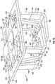
FIG. 1 is an isometric view of a first example box nut retainer according to an embodiment of the present disclosure; -
FIG. 2 is another isometric view of the first example box nut retainer ofFIG. 1 ; -
FIG. 3 is an end view of the first example box nut retainer ofFIGS. 1 and2 ; -
FIG. 4 is another end view of the first example box nut retainer ofFIGS. 1-3 ; -
FIG. 5 is a side view of the first example box nut retainer ofFIGS. 1-4 ; -
FIG. 6 is another side view of the first example box nut retainer ofFIGS. 1-5 ; -
FIG. 7 is a top view of the first example box nut retainer ofFIGS. 1-6 ; -
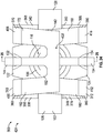
FIG. 8 is a bottom view of the first example box nut retainer ofFIGS. 1-7 ; -
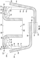
FIG. 9 is a cross-sectional view of the first example box nut retainer ofFIGS. 1-8 taken along line 9-9 ofFIG. 8 ; -
FIG. 10 is an isometric view of the first example box nut retainer ofFIGS. 1-9 installed in a panel; -
FIG. 11 is a top view of the first example box nut retainer ofFIGS. 1-10 installed in the panel ofFIG. 10 ; -
FIG. 12 is a bottom view of the first example box nut retainer ofFIGS. 1-11 installed in the panel ofFIGS. 10 and11 ; -
FIG. 13 is a cross-sectional view of the first example box nut retainer ofFIGS. 1-12 installed in the panel ofFIGS. 10-12 taken along line 13-13 ofFIG. 12 ; -
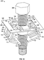
FIG. 14 is a side view of a first example assembly including the first example box nut retainer ofFIGS. 1-13 installed in the panel ofFIGS. 10-13 and utilized with a fastener; -
FIG. 15 is a bottom view of the first example assembly ofFIG. 14 ; -
FIG. 16 is a cross-sectional view of the first example assembly ofFIGS. 13 and14 taken along line 16-16 ofFIG. 15 ; -
FIG. 17 is an isometric view of a second example box nut retainer according to an embodiment of the present disclosure; -
FIG. 18 is another isometric view of the second example box nut retainer ofFIG. 17 ; -
FIG. 19 is an end view of the second example box nut retainer ofFIGS. 17 and18 ; -
FIG. 20 is another end view of the second example box nut retainer ofFIGS. 17-19 ; -
FIG. 21 is a side view of the second example box nut retainer ofFIGS. 17-20 ; -
FIG. 22 is another side view of the second example box nut retainer ofFIGS. 17-21 ; -
FIG. 23 is a top view of the second example box nut retainer ofFIGS. 17-22 ; -
FIG. 24 is a bottom view of the second example box nut retainer ofFIGS. 17-23 ; -
FIG. 25 is a cross-sectional view of the second example box nut retainer ofFIGS. 17-24 taken along line 25-25 ofFIG. 24 ; -
FIG. 26 is a top view of the second example box nut retainer ofFIGS. 17-25 installed in the panel ofFIGS. 10-16 ; -
FIG. 27 is a bottom view of the second example box nut retainer ofFIGS. 17-26 installed in the panel ofFIGS. 10-16 and 26 ; -
FIG. 28 is a cross-sectional view of the second example box nut retainer ofFIGS. 17-27 installed in the panel ofFIGS. 10-16, 26, and 27 taken along line 28-28 ofFIG. 27 ; -
FIG. 29 is a side view of a second example assembly including the second example box nut retainer ofFIGS. 17-28 installed in the panel ofFIGS. 10-16 and 26-28 utilized with the fastener ofFIGS. 14-16 ; -
FIG. 30 is a bottom view of the second example assembly ofFIG. 29 ; and -
FIG. 31 is a cross-sectional view of the second example assembly ofFIGS. 29 and30 taken along line 31-31 ofFIG. 30 . - Before the embodiments of the disclosure are explained in detail, it is to be understood that the disclosure is not limited in its application to the details of construction and the arrangement of the components set forth in the following description or illustrated in the drawings. The disclosure is capable of other embodiments and of being practiced or being carried out in various ways. Also, it is to be understood that the phraseology and terminology used herein are for the purpose of description and should not be regarded as limiting. The use of "including" and "comprising" and variations thereof is meant to encompass the items listed thereafter and equivalents thereof as well as additional items and equivalents thereof.
- Embodiments of the present disclosure provide first and second box nut retainers with features that facilitate installation of the first and second box nut retainers into relatively thin panels and thus provide attachment points for fasteners to the relatively thin panels.
- A first example
box nut retainer 100 according to an embodiment of the present disclosure is depicted inFIGS. 1-16 . Thebox nut retainer 100 includes asupport 102 that extends a length of thebox nut retainer 100. With reference toFIGS. 1-6, 8-10, 12, and 13 , thebox nut retainer 100 further includes afastener sleeve 106, afirst wing 110, and asecond wing 112. - With reference to
FIGS. 1, 2, 8-10, 12, and 13 , thesupport 102 and thefastener sleeve 106 define anopening 116. More specifically, thefastener sleeve 106 extends downwardly from thesupport 102 to define theopening 116. Theopening 116 extends through thesupport 102. Thefastener sleeve 106 is centrally positioned relative to thesupport 102. With reference toFIGS. 1, 2, 7, 8, and 10-12 , thesupport 102 includes afirst tab 122, asecond tab 124, athird tab 126, and afourth tab 128. Thefirst tab 122 is opposite thesecond tab 124. Thethird tab 126 is opposite thefourth tab 128. Thefirst tab 122 is adjacent to thethird tab 126 and thefourth tab 128. Thesecond tab 124 is adjacent to thethird tab 126 and thefourth tab 128. Thus, thesupport 102 is generally cruciform. With reference toFIGS. 1 ,2 ,8 ,10 , and12 , thefastener sleeve 106 is interposed between the first, second, third, andfourth tabs FIGS. 1-4 and 7-13 thefirst tab 122 includes afirst retaining dip 132. Thesecond tab 124 includes asecond retaining dip 134. Thefirst tab 122 is longer than thethird tab 126 and thefourth tab 128. Thesecond tab 124 is longer than thethird tab 126 and thefourth tab 128. - With reference to
FIGS. 1 ,2 , and10 , thefirst wing 110 includes afirst leg 138, asecond leg 140, afirst connector 142, and afirst snap arm 144. Thefirst connector 142 is connected to thefirst leg 138 and thesecond leg 140. Thefirst snap arm 144 extends from thefirst connector 142 between thefirst leg 138 and thesecond leg 140. Thefirst leg 138 and thesecond leg 140 are C-shaped. Thefirst snap arm 144 is L-shaped. Thefirst snap arm 144 extends outwardly and diagonally beyond thefirst leg 138 and thesecond leg 140 toward thesupport 102. Thefirst snap arm 144 extends beyond thesupport 102. - With reference to
FIGS. 1 ,2 , and10 , the second wing includes athird leg 148, afourth leg 150, asecond connector 152, andsecond snap arm 154. Thesecond connector 152 is connected to thethird leg 148 and thefourth leg 150. Thesecond snap arm 154 extends from thesecond connector 152 between thethird leg 148 and thefourth leg 150 toward thesupport 102. Thethird leg 148 and thefourth leg 150 are C-shaped. Thesecond snap arm 154 is L-shaped. Thesecond snap arm 154 extends outwardly and diagonally beyond thethird leg 148 and thefourth leg 150 toward thesupport 102. Thesecond snap arm 154 extends beyond thesupport 102. Thefirst snap arm 144 and thesecond snap arm 154 extend oppositely from one another. - With reference to
FIGS. 1 ,2 , and10 , thefirst wing 110 and thesecond wing 112 are connected to thesupport 102 opposite one another. With reference toFIGS. 1 and10 , more specifically, thefirst leg 138 and thethird leg 148 are connected to thethird tab 126 opposite one another. Further, thesecond leg 140 and thefourth leg 150 are connected to thefourth tab 128 opposite one another. - With reference to
FIG. 4 , thefirst leg 138 includes a firsttop extender 158, afirst descender 160, and a firstbottom extender 162. The firsttop extender 158 includes afirst kink 164. Thefirst kink 164 is arcuate. The firsttop extender 158 is connected to thesupport 102 via thethird tab 126. Thefirst descender 160 is connected to the firsttop extender 158 and to the firstbottom extender 162. The firsttop extender 158 extends curvilinearly and downwardly from thethird tab 126 between thefastener sleeve 106 and thefirst tab 122. - With reference to
FIG. 3 , thesecond leg 140 includes a secondtop extender 168, asecond descender 170, and a secondbottom extender 172. The second top extender includes asecond kink 174. Thesecond kink 174 is arcuate. The secondtop extender 168 is connected to thesupport 102 via thefourth tab 128. Thesecond descender 170 is connected to the secondtop extender 168 and the secondbottom extender 172. The secondtop extender 168 extends curvilinearly and downwardly from thefourth tab 128 between thefastener sleeve 106 and thefirst tab 122. With reference toFIG. 8 , the firstbottom extender 162 is connected to the secondbottom extender 172 via thefirst connector 142. - With reference to
FIG. 4 , thethird leg 148 includes a thirdtop extender 178, athird descender 180, and a thirdbottom extender 182. The thirdtop extender 178 includes athird kink 184. Thethird kink 184 is arcuate. The thirdtop extender 178 is connected to thesupport 102 via thethird tab 126 opposite the firsttop extender 158. Thethird descender 180 is connected to the thirdtop extender 178 and to the thirdbottom extender 182. The thirdtop extender 178 extends curvilinearly and downwardly from thethird tab 126 between thefastener sleeve 106 and thesecond tab 124. - With reference to
FIG. 3 , thefourth leg 150 includes a fourthtop extender 188, afourth descender 190, and a fourthbottom extender 192. The fourth top extender includes afourth kink 194. Thefourth kink 194 is arcuate. The fourthtop extender 188 is connected to thesupport 102 via thefourth tab 128 opposite the secondtop extender 168. Thefourth descender 190 is connected to the fourthtop extender 188 and the fourthbottom extender 192. The fourthtop extender 188 extends curvilinearly and downwardly from thefourth tab 128 between thefastener sleeve 106 and thesecond tab 124. With reference toFIG. 8 , the thirdbottom extender 182 is connected to the fourthbottom extender 192 via thesecond connector 152. - With reference to
FIG. 7 , the firsttop extender 158 and the secondtop extender 168 are generally parallel to one another. The thirdtop extender 178 and the fourthtop extender 188 are generally parallel to one another. - With reference to
FIG. 4 , thefirst descender 160 and the firsttop extender 158 define a firsttop corner 198. Additionally, thefirst descender 160 and the firstbottom extender 162 define a firstbottom corner 200. - With reference to
FIG. 3 , thesecond descender 170 and the secondtop extender 168 define a secondtop corner 204. Additionally, thesecond descender 170 and the secondbottom extender 172 define a secondbottom corner 206. - With reference to
FIG. 4 , thethird descender 180 and the thirdtop extender 178 define a thirdtop corner 210. Additionally, thethird descender 180 and the thirdbottom extender 182 define a thirdbottom corner 212. - With reference to
FIG. 3 , thefourth descender 190 and the fourthtop extender 188 define a fourthtop corner 216. Additionally, thefourth descender 190 and the fourthbottom extender 192 define a fourthbottom corner 218. - With reference to
FIGS. 1-13 , thebox nut retainer 100 is shown in arelaxed state 224. With reference toFIGS. 14-16 , thebox nut retainer 100 is shown is a deployedstate 226. With reference toFIGS. 1-4 and 7-13 , when thebox nut retainer 100 is in therelaxed state 224, thefirst wing 110 and thesecond wing 112 overlap one another at anoverlap region 232. With reference toFIGS. 1, 2, and 7-13 , theoverlap region 232 at least partially overshadows theopening 116. With reference toFIG. 3 , when thebox nut retainer 100 is in therelaxed state 224, the secondtop corner 204 is below thesupport 102 between thefastener sleeve 106 and thefirst tab 122. When thebox nut retainer 100 is in therelaxed state 224, the fourthtop corner 216 is below thesupport 102 between thefastener sleeve 106 and thesecond tab 124. With reference toFIG. 4 , when thebox nut retainer 100 is in therelaxed state 224, the firsttop corner 198 is below thesupport 102 between thefastener sleeve 106 and thefirst tab 122. When thebox nut retainer 100 is in therelaxed state 224, the thirdtop corner 210 is below thesupport 102 between thefastener sleeve 106 and thesecond tab 124. - With reference to
FIGS. 10-13 , the first examplebox nut retainer 100 is installed in apanel 236. Thepanel 236 defines anaperture 238. With reference toFIGS. 10 ,11 , and13 , thepanel 236 includeswalls 240 and atop surface 242. With reference toFIGS. 12 and13 , thepanel 236 includes abottom surface 244. With reference toFIGS. 10-13 , more specifically, thewalls 240 define theaperture 238. With reference toFIGS. 10-12 , theaperture 238 is noncircular (e.g., rectangular, square, polygonal, ovate, etc.). - With reference to
FIGS. 14-17 , the first examplebox nut retainer 100 is installed in thepanel 236 and engaged with a fastener 248 (e.g., a screw or a bolt). Thefastener 248 is externally threaded. Thefastener sleeve 106 is configured to receive thefastener 248. In some embodiments, thefastener sleeve 106 is internally threaded to guide and/or align thefastener 248 to traverse through thefastener sleeve 106. - With reference to
FIGS. 14-17 , additionally or alternatively, thefastener sleeve 106 may be configured to accept a specific type of fastener. As but one non-limiting example, thefastener sleeve 106 may be configured to accept M series fasteners. Thefastener sleeve 106 may be configured to have an inner diameter compatible with a specific M series fastener. Optionally, the M series screws and/or bolts are based on the International Organization for Standardization (ISO) 965, "ISO General Purpose Metric Screw Thread - Tolerances," the American National Standards Institute B4.2-1978, "Preferred Metric Limits and Fits," the American National Standards Institute B1.13M, "Metric Screw Threads: M Profile," and/or the like. In other examples, thefastener sleeve 106 may be configured to accept non-threaded fasteners (e.g., rivets, barbed push-in fasteners, rods, dowels, etc.). - With reference to
FIGS. 10 and11 , in operation, when the first examplebox nut retainer 100 is installed into thepanel 236, thesupport 102, thefirst wing 110, and thesecond wing 112 engage thepanel 236. Thebox nut retainer 100 is introduced into theaperture 238 via thefirst wing 110 and thesecond wing 112. - With reference to
FIG. 13 , it should be understood that, in operation, thefirst snap arm 144 and thesecond snap arm 154 deflect inwardly toward thefastener sleeve 106 as thefirst wing 110 and thesecond wing 112 are inserted into theaperture 238. Once thefirst snap arm 144 and thesecond snap arm 154 clear thebottom surface 244, thefirst snap arm 144 and thesecond snap arm 154 resiliently snap outwardly away fromfastener sleeve 106. Thus, thefirst snap arm 144 and thesecond snap arm 154 prevent thebox nut retainer 100 from being pulled out of theaperture 238 of thepanel 236. With reference toFIGS. 10 and11 , thethird tab 126 and thefourth tab 128 engage thetop surface 242 to prevent thebox nut retainer 100 from being pushed completely through theaperture 238 of thepanel 236. With reference toFIG. 10 , in other words, thethird tab 126, thefourth tab 128, thefirst snap arm 144, and thesecond snap arm 154 transversely retain thebox nut retainer 100 in theaperture 238 of thepanel 236. It should be understood that when thebox nut retainer 100 is installed in thepanel 236 and in therelaxed state 224, thethird tab 126, thefourth tab 128, thefirst snap arm 144, and thesecond snap arm 154 loosely retain thebox nut retainer 100 in theaperture 238 of thepanel 236. - With reference to
FIGS. 10-12 , thefirst wing 110, thesecond wing 112, thefirst tab 122, and thesecond tab 124 engage thewalls 240 of thepanel 236. More specifically, with reference toFIGS. 10 and13 , when thebox nut retainer 100 is installed in thepanel 236, thefirst retaining dip 132 and thesecond retaining dip 134 are partially disposed between thetop surface 242 and thebottom surface 244 to abuttingly engage thewalls 240. Further, the secondtop extender 168 and the fourthtop extender 188 are partially disposed between thetop surface 242 and thebottom surface 244 to abuttingly engage thewalls 240. Additionally, with reference toFIG. 10 , the firsttop extender 158 and the thirdtop extender 178 are partially disposed between thetop surface 242 and thebottom surface 244 to abuttingly engage thewalls 240. Thus, thefirst retaining dip 132, thesecond retaining dip 134, the firsttop extender 158, the secondtop extender 168, the thirdtop extender 178, and the fourthtop extender 188 prevent thebox nut retainer 100 from sliding relative to thepanel 236. In other words, thesupport 102, thefirst wing 110, and thesecond wing 112 laterally retain thebox nut retainer 100 in theaperture 238 of thepanel 236. - With reference to
FIG. 13 , when thebox nut retainer 100 is installed in thepanel 236 and in therelaxed state 224, the secondtop corner 204, thesecond kink 174, the fourthtop corner 216, and thefourth kink 194 are between thetop surface 242 and thebottom surface 244. Additionally, with reference toFIG. 10 , when thebox nut retainer 100 is installed in thepanel 236 and in therelaxed state 224, the firsttop corner 198, thefirst kink 164, the thirdtop corner 210, and thethird kink 184 are between thetop surface 242 and thebottom surface 244. - With reference to
FIG. 14 , further in operation, as thefastener 248 is threaded into thefastener sleeve 106, thefastener 248 initially contacts thesecond wing 112 and subsequently contacts thefirst wing 110. As thefastener 248 is threadingly driven against thefirst wing 110 and thesecond wing 112, thefirst wing 110 and thesecond wing 112 pivot relative to thesupport 102 to deflect outwardly away from thefastener sleeve 106 into the deployedstate 226. More specifically, thefirst leg 138, thesecond leg 140, thethird leg 148, and thefourth leg 150 respectively bend at thefirst kink 164, thesecond kink 174, thethird kink 184, and thefourth kink 194. When thebox nut retainer 100 is in the deployedstate 226, the firsttop corner 198, the secondtop corner 204, the thirdtop corner 210, and the fourthtop corner 216 are pushed out of theaperture 238 beyond thetop surface 242 and thesupport 102. Thus, with reference toFIGS. 14 and16 , when thebox nut retainer 100 is in the deployedstate 226, thesecond descender 170 and thefourth descender 190 contact thewalls 240 and thebottom surface 244. With reference toFIG. 14 , thefirst descender 160 and thethird descender 180 also contact thewalls 240 and thebottom surface 244. In other words, as thefirst wing 110 and thesecond wing 112 deploy under pressure applied by thefastener 248, thefirst descender 160, thesecond descender 170, thethird descender 180, and thefourth descender 190 are driven against thewalls 240 and thebottom surface 244 to draw thethird tab 126 and thefourth tab 128 against thetop surface 242. Thus, when thebox nut retainer 100 is installed in thepanel 236 and in the deployedstate 226, thethird tab 126, thefourth tab 128, thefirst wing 110, and thesecond wing 112 tightly retain thebox nut retainer 100 in theaperture 238 of thepanel 236. In other words, when thebox nut retainer 100 is installed in thepanel 236 and in the deployedstate 226, thepanel 236 is clamped between thesupport 102 and thefirst wing 110 and between thesupport 102 and thesecond wing 112. - With reference to
FIGS. 14-16 , it should be understood that additional components (e.g., a second panel, a wiring harness, a brake line router, etc.) (not shown) may be used with thefastener 248. Thefastener 248 may be driven into thebox nut retainer 100 to robustly attach the additional components to thepanel 236. - A second example
box nut retainer 300 according to an embodiment of the present disclosure is depicted inFIGS. 17-31 . With reference toFIGS. 17-22, 24, 25, 27-29, and 31 thebox nut retainer 300 includes thesupport 102 and thefastener sleeve 106 as described above. Thebox nut retainer 300 also includes afirst wing 310 and asecond wing 312. - With reference to
FIGS. 17 and18 , thefirst wing 310 includes afirst leg 338, asecond leg 340, thefirst connector 142, and thefirst snap arm 144. Thefirst connector 142 is connected to thefirst leg 338 and thesecond leg 340. Thefirst snap arm 144 extends from thefirst connector 142 between thefirst leg 338 and thesecond leg 340. Thefirst leg 338 and thesecond leg 340 are C-shaped. Thefirst snap arm 144 is L-shaped. Thefirst snap arm 144 extends outwardly and diagonally beyond thefirst leg 338 and thesecond leg 340 toward thesupport 102. Thefirst snap arm 144 extends beyond thesupport 102. - With reference to
FIGS. 17 and18 , thesecond wing 312 includes athird leg 348, afourth leg 350, thesecond connector 152, and thesecond snap arm 154. Thesecond connector 152 is connected to thethird leg 348 and thefourth leg 350. Thesecond snap arm 154 extends from thesecond connector 152 between thethird leg 348 and thefourth leg 350. Thethird leg 348 and thefourth leg 350 are C-shaped. Thesecond snap arm 154 is L-shaped. Thesecond snap arm 154 extends outwardly and diagonally beyond thethird leg 348 and thefourth leg 350 toward thesupport 102. Thesecond snap arm 154 extends beyond thesupport 102. Thefirst snap arm 144 and thesecond snap arm 154 extend oppositely from one another. - With reference to
FIGS. 17 and18 , thefirst wing 310 and thesecond wing 312 are connected to thesupport 102 opposite one another. More specifically, thefirst leg 338 and thethird leg 348 are connected to thethird tab 126 opposite one another. Further, thesecond leg 340 and thefourth leg 350 are connected to thefourth tab 128 opposite one another. - With reference to
FIG. 20 , thefirst leg 338 includes a firsttop extender 358, afirst descender 360, and the firstbottom extender 162. The firsttop extender 358 is connected to thesupport 102 via thethird tab 126. Thefirst descender 360 is connected to the firsttop extender 158 and to the firstbottom extender 162. The firsttop extender 358 extends diagonally and downwardly from thethird tab 126 between thefastener sleeve 106 and thefirst tab 122. - With reference to
FIG. 19 , thesecond leg 340 includes a secondtop extender 368, asecond descender 370, and the secondbottom extender 172. The secondtop extender 368 is connected to thesupport 102 via thefourth tab 128. Thesecond descender 370 is connected to the secondtop extender 368 and the secondbottom extender 172. The secondtop extender 368 extends diagonally and downwardly from thefourth tab 128 between thefastener sleeve 106 and thefirst tab 122. With reference toFIG. 24 , the firstbottom extender 162 is connected to the secondbottom extender 172 via thefirst connector 142. - With reference to
FIG. 20 , thethird leg 348 includes a thirdtop extender 378, athird descender 380, and the thirdbottom extender 182. The thirdtop extender 378 is connected to thesupport 102 via thethird tab 126 opposite the firsttop extender 358. Thethird descender 180 is connected to the thirdtop extender 378 and to the thirdbottom extender 182. The thirdtop extender 378 extends diagonally and downwardly from thethird tab 126 between thefastener sleeve 106 and thesecond tab 124. - With reference to
FIG. 19 , thefourth leg 350 includes a fourthtop extender 388, afourth descender 390, and the fourthbottom extender 192. The fourthtop extender 388 is connected to thesupport 102 via thefourth tab 128 opposite the secondtop extender 368. Thefourth descender 390 is connected to the fourthtop extender 388 and the fourthbottom extender 192. The fourthtop extender 388 extends diagonally and downwardly from thefourth tab 128 between thefastener sleeve 106 and thesecond tab 124. With reference toFIG. 24 , the thirdbottom extender 182 is connected to the fourthbottom extender 192 via thesecond connector 152. - With reference to
FIG. 23 , the firsttop extender 358 and the secondtop extender 368 are generally parallel to one another. The thirdtop extender 378 and the fourthtop extender 388 are generally parallel to one another. - With reference to
FIG. 20 , thefirst descender 360 and the firsttop extender 358 define a firsttop corner 398. Additionally, thefirst descender 360 and the first bottom extender 362 define a firstbottom corner 400. - With reference to
FIG. 19 , thesecond descender 370 and the secondtop extender 368 define a secondtop corner 404. Additionally, thesecond descender 370 and the secondbottom extender 372 define a secondbottom corner 406. - With reference to
FIG. 20 , thethird descender 380 and the thirdtop extender 378 define a thirdtop corner 410. Additionally, thethird descender 380 and the thirdbottom extender 182 define a thirdbottom corner 412. - With reference to
FIG. 19 , thefourth descender 390 and the fourthtop extender 388 define a fourthtop corner 416. Additionally, thefourth descender 390 and the fourthbottom extender 192 define a fourthbottom corner 418. - With reference to
FIGS. 17-28 , thebox nut retainer 300 is shown in arelaxed state 424. With reference toFIGS. 29-31 , thebox nut retainer 300 is shown in a deployed state 426. With reference toFIGS. 17-20 and 23-28 , when thebox nut retainer 300 is in therelaxed state 424, thefirst wing 310 and thesecond wing 312 overlap one another at anoverlap region 432. With reference toFIGS. 17, 18, and 23-28 theoverlap region 232 at least partially overshadows theopening 116. With reference toFIG. 19 , when thebox nut retainer 300 is in therelaxed state 424, the secondtop corner 404 is below thesupport 102 between thefastener sleeve 106 and thefirst tab 122. When thebox nut retainer 300 is in therelaxed state 424, the fourthtop corner 416 is below thesupport 102 between thefastener sleeve 106 and thesecond tab 124. With reference toFIG. 20 , when thebox nut retainer 300 is in therelaxed state 424, the firsttop corner 398 is below thesupport 102 between thefastener sleeve 106 and thefirst tab 122. When thebox nut retainer 300 is in therelaxed state 424, the thirdtop corner 410 is below thesupport 102 between thefastener sleeve 106 and thesecond tab 124. - With reference to
FIGS. 26-28 , the second examplebox nut retainer 300 is installed in thepanel 236. Thepanel 236 is as described above. - With reference to
FIGS. 29-31 , the second examplebox nut retainer 300 is installed in thepanel 236 and engaged with thefastener 248. Thefastener 248 is as described above. - With reference to
FIG. 26 , in operation, when the second examplebox nut retainer 300 is installed into thepanel 236, thesupport 102, thefirst wing 310, and thesecond wing 312 engage thepanel 236. Thebox nut retainer 300 is introduced into theaperture 238 via thefirst wing 310 and thesecond wing 312. - With reference to
FIG. 28 , it should be understood that, in operation, thefirst snap arm 144 and thesecond snap arm 154 deflect inwardly toward thefastener sleeve 106 as thefirst wing 310 and thesecond wing 312 are inserted into theaperture 238. Once thefirst snap arm 144 and thesecond snap arm 154 clear thebottom surface 244, thefirst snap arm 144 and thesecond snap arm 154 resiliently snap outwardly away fromfastener sleeve 106. Thus, thefirst snap arm 144 and thesecond snap arm 154 prevent thebox nut retainer 300 from being pulled out of theaperture 238 of thepanel 236. With reference toFIG. 26 , thethird tab 126 and thefourth tab 128 engage thetop surface 242 to prevent thebox nut retainer 300 from being pushed completely through theaperture 238 of thepanel 236. In other words, thethird tab 126, thefourth tab 128, thefirst snap arm 144, and the second snap arm 154 (shown inFIG. 28 ) transversely retain thebox nut retainer 300 in theaperture 238 of thepanel 236. It should be understood that when thebox nut retainer 300 is installed in thepanel 236 and in therelaxed state 224, thethird tab 126, thefourth tab 128, thefirst snap arm 144, and the second snap arm 154 (shown inFIG. 28 ) loosely retain thebox nut retainer 300 in theaperture 238 of thepanel 236. - With reference to
FIGS. 26-28 , thefirst wing 310, thesecond wing 312, thefirst tab 122, and thesecond tab 124 engage thewalls 240 of thepanel 236. More specifically, with reference toFIG. 28 , when thebox nut retainer 300 is installed in thepanel 236, thefirst retaining dip 132 and thesecond retaining dip 134 are partially disposed between thetop surface 242 and thebottom surface 244 to abuttingly engage thewalls 240. Further, the secondtop extender 368 and the fourthtop extender 388 are disposed between thetop surface 242 and thebottom surface 244 to abuttingly engage thewalls 240. Additionally, with reference toFIG. 26 , the firsttop extender 358 and the thirdtop extender 378 are disposed between thetop surface 242 and the bottom surface 244 (shown inFIG. 28 ) to abuttingly engage thewalls 240. Thus, thefirst retaining dip 132, thesecond retaining dip 134, the firsttop extender 358, the secondtop extender 368, the thirdtop extender 378, and the fourthtop extender 388 prevent thebox nut retainer 300 from sliding relative to thepanel 236. In other words, thesupport 102, thefirst wing 310, and thesecond wing 312 laterally retain thebox nut retainer 300 in theaperture 238 of thepanel 236. - With reference to
FIG. 28 , when thebox nut retainer 300 is installed in thepanel 236 and in therelaxed state 424, the secondtop corner 404 and the fourthtop corner 216 are aligned with thebottom surface 244. Additionally, with reference toFIG. 27 , when thebox nut retainer 300 is installed in thepanel 236 and in therelaxed state 224, the firsttop corner 398 and the thirdtop corner 410 are aligned with thebottom surface 244. - With reference to
FIG. 29 , further in operation, as thefastener 248 is threaded into thefastener sleeve 106, thefastener 248 initially contacts thesecond wing 312 and subsequently contacts thefirst wing 310. As thefastener 248 is threadingly driven against thefirst wing 310 and thesecond wing 312, thefirst wing 310 and thesecond wing 312 pivot relative to the support to deflect outwardly away from thefastener sleeve 106 into the deployed state 426. More specifically, thefirst leg 338, thesecond leg 340, thethird leg 348, and thefourth leg 350 bend upwardly toward thebottom surface 244. When thebox nut retainer 300 is in the deployed state 426, the firsttop corner 398, the secondtop corner 404, the thirdtop corner 410, and the fourthtop corner 416 are pushed out of theaperture 238 beyond thetop surface 242 to align with thesupport 102. Thus, with reference toFIGS. 29 and31 , when thebox nut retainer 300 is in the deployed state 426, thesecond descender 370 and thefourth descender 390 contact thewalls 240 and thebottom surface 244. With reference toFIG. 29 , thefirst descender 360 and thethird descender 380 also contact thewalls 240 and thebottom surface 244. In other words, as thefirst wing 310 and thesecond wing 312 deploy under pressure applied by thefastener 248, thefirst descender 360, thesecond descender 370, thethird descender 380, and thefourth descender 390 are driven against thewalls 240 and thebottom surface 244 to draw thethird tab 126 and thefourth tab 128 against thetop surface 242. Thus, when thebox nut retainer 300 is installed in thepanel 236 and in the deployedstate 226, thethird tab 126, thefourth tab 128, thefirst wing 310, and thesecond wing 312 tightly retain thebox nut retainer 300 in theaperture 238 of thepanel 236. In other words, when thebox nut retainer 100 is installed in thepanel 236 and in the deployedstate 226, thepanel 236 is clamped between thesupport 102 and thefirst wing 310 and between thesupport 102 and thesecond wing 312. - With reference to
FIGS. 29-31 , it should be understood that additional components (e.g., a second panel, a wiring harness, a brake line router, etc.) (not shown) may be used with thefastener 248. Thefastener 248 may be driven into thebox nut retainer 300 to robustly attach the additional components to thepanel 236. - As used herein, panel may refer to any component that may be attached or assembled to another component. Any of the panels described herein may be made of any suitable material, for example, a metal or plastic material.
- Embodiments of the present disclosure provide a fastening system, and, more particularly, a box nut retainer system that is configured to securely connect multiple components together. The box nut retainer system includes opposing wings with top corners between a support and a fastener sleeve, which direct the wings to engage with a bottom surface of a panel while the support clamps against a top surface of the panel.
- From the foregoing, it will be appreciated that the above first and second example
box nut retainers box nut retainers box nut retainers box nut retainers box nut retainer 100 conserves resources and may improve vehicle fuel efficiency as compared to existing fasteners. - While various spatial and directional terms, such as top, bottom, lower, mid, lateral, horizontal, vertical, front and the like may be used to describe embodiments of the present disclosure, it is understood that such terms are merely used with respect to the orientations shown in the drawings. The orientations may be inverted, rotated, or otherwise changed, such that an upper portion is a lower portion, and vice versa, horizontal becomes vertical, and the like.
- Variations and modifications of the foregoing are within the scope of the present disclosure. It is understood that the embodiments disclosed and defined herein extend to all alternative combinations of two or more of the individual features mentioned or evident from the text and/or drawings. All of these different combinations constitute various alternative aspects of the present disclosure. The embodiments described herein explain the best modes known for practicing the disclosure and will enable others skilled in the art to utilize the disclosure. The claims are to be construed to include alternative embodiments to the extent permitted by the prior art.
- To the extent used in the appended claims, the terms "including" and "in which" are used as the plain-English equivalents of the respective terms "comprising" and "wherein." Moreover, to the extent used in the following claims, the terms "first," "second," and "third," etc. are used merely as labels, and are not intended to impose numerical requirements on their objects. Further, the limitations of the following claims are not written in means-plus-function format and are not intended to be interpreted based on 35 U.S.C. § 112(f), unless and until such claim limitations expressly use the phrase "means for" followed by a statement of function void of further structure.
- Various features of the disclosure are set forth in the appended claims.
- Certain embodiments are described in the following numbered clauses:
- Clause 1. A box nut retainer, comprising:
- a support;
- a fastener sleeve defining an opening and extending downwardly from the support; and
- a wing extending from the support and having a top corner between the support and the fastener sleeve.
- Clause 2. The box nut retainer of clause 1, wherein the wing has a top extender connected to the support and extending between the support and the fastener sleeve.
- Clause 3. The box nut retainer of clause 2, wherein the wing has a descender connected to the top extender, the top extender and the descender defining the top corner.
- Clause 4. The box nut retainer of clause 1, wherein the fastener sleeve is internally threaded.
- Clause 5. The box nut retainer of clause 1, wherein the wing has a snap arm extending toward the support.
- Clause 6. The box nut retainer of clause 5, wherein the snap arm extends beyond the support.
-
Clause 7. The box nut retainer of clause 5, wherein the snap arm is L-shaped. - Clause 8. The box nut retainer of clause 5, wherein the snap arm pivots resiliently relative to a leg of the wing.
- Clause 9. The box nut retainer of clause 1, wherein the wing partially overshadows the opening.
- Clause 10. The box nut retainer of clause 1, wherein the support has a retaining dip.
- Clause 11. The box nut retainer of clause 1, wherein the wing is C-shaped.
- Clause 12. The box nut retainer of clause 1, wherein the wing is a first wing and further comprising a second wing extending from the support and overlapping the first wing.
-
Clause 13. The box nut retainer of clause 1, wherein the support has a first tab and a second tab, the first tab being longer than the second tab. - Clause 14. The box nut retainer of clause 1, wherein:
- the top corner is a first top corner,
- the wing has a first leg connected to a second leg,
- the first leg includes the first top corner, and
- the second leg includes a second top corner.
- Clause 15. The box nut retainer of clause 1, wherein the wing is configured to deploy against a bottom surface of a panel to draw the support against a top surface of the panel.
-
Clause 16. A box nut retainer, comprising:- a support;
- a fastener sleeve defining an opening and extending downwardly from the support; and
- a wing having a kink extending curvilinearly from the support to a top corner between the support and the fastener sleeve.
- Clause 17. The box nut retainer of
clause 16, wherein the wing has a descender connected to the kink, the kink and the descender defining the top corner. - Clause 18. The box nut retainer of
clause 16, wherein the wing pivots relative to the support via the kink. - Clause 19. A box nut retainer, comprising:
- a support;
- a fastener sleeve defining an opening and extending downwardly from the support; and
- a wing having a top extender extending diagonally from the support to a top corner between the support and the fastener sleeve.
- Clause 20. The box nut retainer of clause 19, wherein:
- the wing has a descender connected to the top extender via the top corner, and
- the wing is configured to pivot relative to the support to drive the descender against a bottom surface of a panel to draw the support against a top surface of the panel.
Claims (15)
- A box nut retainer, comprising:a support;a fastener sleeve defining an opening and extending downwardly from the support; anda wing extending from the support and having a top corner between the support and the fastener sleeve.
- The box nut retainer of claim 1, wherein the wing has a top extender connected to the support and extending between the support and the fastener sleeve, and, optionally, wherein the wing has a descender connected to the top extender, the top extender and the descender defining the top corner.
- The box nut retainer of claim 1, wherein the wing has a snap arm extending toward the support.
- The box nut retainer of claim 3, wherein:the snap arm extends beyond the support; orthe snap arm is L-shaped.
- The box nut retainer of claim 3, wherein the snap arm pivots resiliently relative to a leg of the wing.
- The box nut retainer of claim 1, wherein:the wing partially overshadows the opening; orthe wing is C-shaped.
- The box nut retainer of claim 1, wherein the support has a retaining dip.
- The box nut retainer of claim 1, wherein the wing is a first wing and further comprising a second wing extending from the support and overlapping the first wing.
- The box nut retainer of claim 1, wherein the support has a first tab and a second tab, the first tab being longer than the second tab.
- The box nut retainer of claim 1, wherein:the top corner is a first top corner,the wing has a first leg connected to a second leg,the first leg includes the first top corner, andthe second leg includes a second top corner.
- The box nut retainer of claim 1, wherein the wing is configured to deploy against a bottom surface of a panel to draw the support against a top surface of the panel.
- A box nut retainer, comprising:a support;a fastener sleeve defining an opening and extending downwardly from the support; anda wing having a kink extending curvilinearly from the support to a top corner between the support and the fastener sleeve.
- The box nut retainer of claim 12, wherein:the wing has a descender connected to the kink, the kink and the descender defining the top corner; orthe wing pivots relative to the support via the kink.
- A box nut retainer, comprising:a support;a fastener sleeve defining an opening and extending downwardly from the support; anda wing having a top extender extending diagonally from the support to a top corner between the support and the fastener sleeve.
- The box nut retainer of claim 14, wherein:the wing has a descender connected to the top extender via the top corner, andthe wing is configured to pivot relative to the support to drive the descender against a bottom surface of a panel to draw the support against a top surface of the panel.
Applications Claiming Priority (2)
| Application Number | Priority Date | Filing Date | Title |
|---|---|---|---|
| US201962890395P | 2019-08-22 | 2019-08-22 | |
| US16/998,758 US11692581B2 (en) | 2019-08-22 | 2020-08-20 | Box nut retainer |
Publications (2)
| Publication Number | Publication Date |
|---|---|
| EP3783232A1 true EP3783232A1 (en) | 2021-02-24 |
| EP3783232B1 EP3783232B1 (en) | 2023-10-04 |
Family
ID=72290755
Family Applications (1)
| Application Number | Title | Priority Date | Filing Date |
|---|---|---|---|
| EP20192128.5A Active EP3783232B1 (en) | 2019-08-22 | 2020-08-21 | Box nut retainer |
Country Status (3)
| Country | Link |
|---|---|
| US (1) | US11692581B2 (en) |
| EP (1) | EP3783232B1 (en) |
| CN (1) | CN112412953B (en) |
Families Citing this family (6)
| Publication number | Priority date | Publication date | Assignee | Title |
|---|---|---|---|---|
| USD995278S1 (en) * | 2019-10-01 | 2023-08-15 | Illinois Tool Works Inc. | Nut retainer |
| US12049916B2 (en) * | 2021-02-05 | 2024-07-30 | Erico International Corporation | Spring nut |
| USD1065996S1 (en) * | 2022-07-08 | 2025-03-11 | Illinois Tool Works Inc. | Fastener |
| USD1049841S1 (en) * | 2022-08-24 | 2024-11-05 | Illinois Tool Works Inc. | Fastener |
| US20240068501A1 (en) * | 2022-08-31 | 2024-02-29 | Illinois Tool Works Inc. | Corner Engage Clip with Integral Support Flange |
| US12290890B2 (en) | 2023-02-16 | 2025-05-06 | Doben Limited | Automated floating insertion tool for push-in fasteners |
Citations (4)
| Publication number | Priority date | Publication date | Assignee | Title |
|---|---|---|---|---|
| US7789606B2 (en) * | 2004-04-01 | 2010-09-07 | Illinois Tool Works Inc. | Push-in nut |
| US8388289B2 (en) * | 2010-04-05 | 2013-03-05 | GM Global Technology Operations LLC | Self-supporting bracket nut |
| DE202013100387U1 (en) * | 2013-01-28 | 2013-03-11 | Fath Gmbh | threaded fastener |
| WO2018144210A1 (en) * | 2017-01-31 | 2018-08-09 | Illinois Tool Works Inc. | Ergonomic box nut retainer |
Family Cites Families (62)
| Publication number | Priority date | Publication date | Assignee | Title |
|---|---|---|---|---|
| USD274674S (en) | 1981-11-18 | 1984-07-17 | `Totes`, Incorporated | Umbrella handle |
| US5759004A (en) * | 1993-04-20 | 1998-06-02 | Panduit Corp. | MLT bent leg pushmount |
| DE69633469T2 (en) | 1995-09-19 | 2005-11-17 | Daiwa Kasei Kogyo K.K., Okazaki | Flexible retaining leg for clamping device |
| US5919019A (en) | 1998-01-20 | 1999-07-06 | California Industrial Products, Inc. | Mid-panel nut |
| US7168138B2 (en) | 2000-03-27 | 2007-01-30 | Newfrey Llc | Resilient clip fastener |
| US6629809B2 (en) * | 2000-11-08 | 2003-10-07 | Termax Corporation | Sheet metal fastener with multiple engagement |
| US6908274B1 (en) * | 2000-11-20 | 2005-06-21 | Termax Corporation | Combination fastener |
| US7120971B2 (en) | 2001-03-02 | 2006-10-17 | Newfrey Llc | Low insertion effort u-base retainer |
| US6718599B2 (en) | 2001-06-25 | 2004-04-13 | Termax Corporation | Spring fastener with ergonomically balanced removal to insertion force ratio |
| US9457734B2 (en) | 2001-06-25 | 2016-10-04 | Termax Corporation | Continuously adaptive fastener clip |
| US7640634B2 (en) | 2002-06-07 | 2010-01-05 | Termax Corporation | Ergonomic fastener |
| US6745440B2 (en) | 2001-07-31 | 2004-06-08 | Eustathios Vassiliou Revocable Trust | Increased holding power spring fasteners |
| USD477318S1 (en) | 2002-04-22 | 2003-07-15 | Mitac International Corp. | Electronic data processing device |
| WO2003100267A1 (en) | 2002-05-28 | 2003-12-04 | Newfrey Llc | Resilient clip fastener and method of manufacturing the same |
| US20040244156A1 (en) * | 2002-06-24 | 2004-12-09 | Nicholas Jackson | Sheet metal fastening clip |
| US7226260B2 (en) | 2002-06-24 | 2007-06-05 | A. Raymond, Inc. | Sheet metal fastening clip |
| US6893197B2 (en) | 2002-10-28 | 2005-05-17 | Newfrey Llc | Caged nut assembly with reinforcing protrusions |
| SK50682005A3 (en) * | 2003-02-19 | 2006-02-02 | Textron Fastening Systems | Fastening device with fastener |
| US7676893B2 (en) | 2005-04-07 | 2010-03-16 | Newfrey Llc | Silencer plating for fasteners |
| TWD114838S1 (en) | 2005-08-23 | 2007-01-01 | 松下電器產業股份有限公司 | LCD projector remote control |
| USD537814S1 (en) | 2005-08-23 | 2007-03-06 | Matsushita Electric Industrial Co., Ltd. | Remote controller for LCD video projector |
| US8167275B1 (en) | 2005-11-30 | 2012-05-01 | The Crane Group Companies Limited | Rail system and method for assembly |
| DE102006001741A1 (en) * | 2006-01-13 | 2007-08-02 | A. Raymond Et Cie | Captive threaded nut for latching into hole in plate is formed with self retaining spring arms |
| KR101048732B1 (en) | 2006-04-26 | 2011-07-14 | 아 레이몽 에 씨에 에스쎄에스 | Fixed devices |
| BRPI0813498A2 (en) * | 2007-06-13 | 2015-01-06 | Monadnock Company | APPARATUS AND METHODS FOR FASTENING A GRIP |
| USD572580S1 (en) | 2007-06-21 | 2008-07-08 | Piolax Inc. | Nut |
| US8016530B2 (en) * | 2008-01-10 | 2011-09-13 | Illinois Tool Works Inc. | Panel fastener |
| USD616851S1 (en) | 2009-06-01 | 2010-06-01 | Sprint Communications Company L.P. | Circular mobile phone |
| US8155692B1 (en) | 2009-06-01 | 2012-04-10 | Sprint Communications Company L.P. | Mobile communications device with rotating keyboards |
| EP2496848B1 (en) | 2009-11-04 | 2016-03-09 | Illinois Tool Works Inc. | Removable and reusable quick nut |
| USD639260S1 (en) | 2010-04-27 | 2011-06-07 | Jlt Group, Inc. | Hand-held mobile communication device |
| US8371544B2 (en) | 2010-08-19 | 2013-02-12 | Gunderson Llc | Pipe anchor for railroad car |
| US9284968B2 (en) | 2011-12-19 | 2016-03-15 | Gary L. Sharpe | Mounting clamp for pole |
| US8800120B2 (en) | 2012-04-27 | 2014-08-12 | Newfrey Llc | High retention fastener |
| DE102012208482A1 (en) | 2012-05-21 | 2013-11-21 | Hilti Aktiengesellschaft | fastening device |
| USD740113S1 (en) | 2013-03-15 | 2015-10-06 | Hubbell Incorporated | Clip-on bonding washer |
| US9643636B2 (en) | 2013-05-01 | 2017-05-09 | P.U.F. Llc | Apparatus for securing a walking assist device |
| CN103398074A (en) * | 2013-08-05 | 2013-11-20 | 无锡市张泾宇钢机械厂 | Pretightening elastic piece with auxiliary plate structure |
| US9826810B2 (en) | 2013-08-30 | 2017-11-28 | Left Field Design, Llc | Compact pocket organizer for keys, cards, currency and tools |
| USD715686S1 (en) | 2013-09-19 | 2014-10-21 | Casey Crafton | Tie clip |
| US9631662B2 (en) * | 2014-03-19 | 2017-04-25 | Ramco Specialties, Inc. | Spring clip apparatus |
| USD716137S1 (en) | 2014-05-05 | 2014-10-28 | Ideavillage Products, Corp. | Clip device |
| JP1518014S (en) | 2014-07-24 | 2015-02-23 | ||
| US9440596B2 (en) * | 2014-11-20 | 2016-09-13 | Ford Global Technologies, Llc | Retention clip for interior vehicle components |
| USD757533S1 (en) | 2015-01-05 | 2016-05-31 | Nite Ize, Inc. | Clip |
| US9562554B2 (en) * | 2015-01-16 | 2017-02-07 | A. Raymond Et Cie | Retainer assembly |
| US9746018B2 (en) | 2015-02-02 | 2017-08-29 | Denso International America, Inc. | Speed nut |
| CN106523503B (en) * | 2015-09-14 | 2019-06-14 | 北京宝沃汽车有限公司 | Spring nut, spring nut component and the vehicle with it |
| JP1559671S (en) | 2015-10-09 | 2016-09-26 | ||
| JP1559345S (en) | 2015-10-09 | 2016-09-26 | ||
| USD808787S1 (en) | 2016-03-15 | 2018-01-30 | L.F. Centennial Ltd. | Clip |
| USD838866S1 (en) | 2016-08-29 | 2019-01-22 | Rokel Enterprises, LLC | Dock connector |
| JP1570331S (en) | 2016-09-14 | 2017-02-27 | ||
| USD825571S1 (en) | 2016-11-16 | 2018-08-14 | BobjGear, LLC | Electronic device cover with fingerswipe indentation |
| JP1599004S (en) | 2017-09-21 | 2018-03-05 | ||
| US20190242424A1 (en) * | 2018-02-05 | 2019-08-08 | Illinois Tool Works Inc. | Snap-in retention nut |
| USD874913S1 (en) | 2018-06-19 | 2020-02-11 | Illinois Tool Works Inc. | Nut retainer |
| USD873128S1 (en) | 2018-12-03 | 2020-01-21 | Sheng-Ching Lu | T-nut |
| USD879104S1 (en) | 2019-01-07 | 2020-03-24 | Jianhui Li | Tablet case |
| USD879105S1 (en) | 2019-01-07 | 2020-03-24 | Jianhui Li | Tablet case |
| USD891240S1 (en) | 2019-08-21 | 2020-07-28 | Illinois Tool Works Inc. | U-nut |
| USD888546S1 (en) | 2019-08-23 | 2020-06-30 | Illinois Tool Works Inc. | Nut retainer |
-
2020
- 2020-08-20 US US16/998,758 patent/US11692581B2/en active Active
- 2020-08-21 EP EP20192128.5A patent/EP3783232B1/en active Active
- 2020-08-24 CN CN202010858329.7A patent/CN112412953B/en active Active
Patent Citations (4)
| Publication number | Priority date | Publication date | Assignee | Title |
|---|---|---|---|---|
| US7789606B2 (en) * | 2004-04-01 | 2010-09-07 | Illinois Tool Works Inc. | Push-in nut |
| US8388289B2 (en) * | 2010-04-05 | 2013-03-05 | GM Global Technology Operations LLC | Self-supporting bracket nut |
| DE202013100387U1 (en) * | 2013-01-28 | 2013-03-11 | Fath Gmbh | threaded fastener |
| WO2018144210A1 (en) * | 2017-01-31 | 2018-08-09 | Illinois Tool Works Inc. | Ergonomic box nut retainer |
Also Published As
| Publication number | Publication date |
|---|---|
| CN112412953A (en) | 2021-02-26 |
| US11692581B2 (en) | 2023-07-04 |
| CN112412953B (en) | 2026-01-30 |
| EP3783232B1 (en) | 2023-10-04 |
| US20210054867A1 (en) | 2021-02-25 |
Similar Documents
| Publication | Publication Date | Title |
|---|---|---|
| EP3783232B1 (en) | Box nut retainer | |
| US11629742B2 (en) | Box nut retainer | |
| US10696403B2 (en) | Aircraft monument floor mounting system | |
| US8376425B2 (en) | Automotive door striker | |
| US10914336B2 (en) | Fastening clip assembly | |
| US20200400180A1 (en) | Trim clip with four point retention | |
| US20190242418A1 (en) | Fastener assembly having a component-isolating grommet | |
| EP3233568B1 (en) | A fastening system | |
| CA2973822A1 (en) | Retainer assembly | |
| US20190366944A1 (en) | Rib clip assembly | |
| US8814394B2 (en) | Adjustable headlamp attachment with pedestrian protection | |
| US20160144698A1 (en) | Vehicle-use seal structure | |
| EP3786467A1 (en) | Ergonomic box nut retainer | |
| US20100038483A1 (en) | Seat track fittings | |
| US20180142714A1 (en) | Fastener-retaining system and method | |
| US8292560B2 (en) | Anchor device with double-sectioned head and method of using the same | |
| US8776325B2 (en) | Trim fastening system | |
| US11882906B2 (en) | Dual engagement fastener | |
| US20230417270A1 (en) | Quarter Turn Retainer | |
| US11486423B2 (en) | Linear latching systems and methods | |
| US10415747B1 (en) | Brackets and assemblies for attaching objects to surfaces in vehicles | |
| US20230349413A1 (en) | Compression Limiter | |
| CN213326223U (en) | Elevator is anti-skidding gasket for guide rail bracket | |
| EP4386221A1 (en) | Fastener clip assembly with multiple threads for receiving a screw | |
| US10927876B1 (en) | Rivet nut fastener |
Legal Events
| Date | Code | Title | Description |
|---|---|---|---|
| PUAI | Public reference made under article 153(3) epc to a published international application that has entered the european phase |
Free format text: ORIGINAL CODE: 0009012 |
|
| STAA | Information on the status of an ep patent application or granted ep patent |
Free format text: STATUS: THE APPLICATION HAS BEEN PUBLISHED |
|
| AK | Designated contracting states |
Kind code of ref document: A1 Designated state(s): AL AT BE BG CH CY CZ DE DK EE ES FI FR GB GR HR HU IE IS IT LI LT LU LV MC MK MT NL NO PL PT RO RS SE SI SK SM TR |
|
| AX | Request for extension of the european patent |
Extension state: BA ME |
|
| STAA | Information on the status of an ep patent application or granted ep patent |
Free format text: STATUS: REQUEST FOR EXAMINATION WAS MADE |
|
| 17P | Request for examination filed |
Effective date: 20210728 |
|
| RBV | Designated contracting states (corrected) |
Designated state(s): AL AT BE BG CH CY CZ DE DK EE ES FI FR GB GR HR HU IE IS IT LI LT LU LV MC MK MT NL NO PL PT RO RS SE SI SK SM TR |
|
| GRAP | Despatch of communication of intention to grant a patent |
Free format text: ORIGINAL CODE: EPIDOSNIGR1 |
|
| STAA | Information on the status of an ep patent application or granted ep patent |
Free format text: STATUS: GRANT OF PATENT IS INTENDED |
|
| INTG | Intention to grant announced |
Effective date: 20230412 |
|
| P01 | Opt-out of the competence of the unified patent court (upc) registered |
Effective date: 20230606 |
|
| GRAS | Grant fee paid |
Free format text: ORIGINAL CODE: EPIDOSNIGR3 |
|
| GRAA | (expected) grant |
Free format text: ORIGINAL CODE: 0009210 |
|
| STAA | Information on the status of an ep patent application or granted ep patent |
Free format text: STATUS: THE PATENT HAS BEEN GRANTED |
|
| AK | Designated contracting states |
Kind code of ref document: B1 Designated state(s): AL AT BE BG CH CY CZ DE DK EE ES FI FR GB GR HR HU IE IS IT LI LT LU LV MC MK MT NL NO PL PT RO RS SE SI SK SM TR |
|
| REG | Reference to a national code |
Ref country code: GB Ref legal event code: FG4D |
|
| REG | Reference to a national code |
Ref country code: CH Ref legal event code: EP |
|
| REG | Reference to a national code |
Ref country code: IE Ref legal event code: FG4D |
|
| REG | Reference to a national code |
Ref country code: DE Ref legal event code: R096 Ref document number: 602020018531 Country of ref document: DE |
|
| REG | Reference to a national code |
Ref country code: LT Ref legal event code: MG9D |
|
| REG | Reference to a national code |
Ref country code: NL Ref legal event code: MP Effective date: 20231004 |
|
| REG | Reference to a national code |
Ref country code: AT Ref legal event code: MK05 Ref document number: 1618027 Country of ref document: AT Kind code of ref document: T Effective date: 20231004 |
|
| PG25 | Lapsed in a contracting state [announced via postgrant information from national office to epo] |
Ref country code: NL Free format text: LAPSE BECAUSE OF FAILURE TO SUBMIT A TRANSLATION OF THE DESCRIPTION OR TO PAY THE FEE WITHIN THE PRESCRIBED TIME-LIMIT Effective date: 20231004 |
|
| PG25 | Lapsed in a contracting state [announced via postgrant information from national office to epo] |
Ref country code: GR Free format text: LAPSE BECAUSE OF FAILURE TO SUBMIT A TRANSLATION OF THE DESCRIPTION OR TO PAY THE FEE WITHIN THE PRESCRIBED TIME-LIMIT Effective date: 20240105 |
|
| PG25 | Lapsed in a contracting state [announced via postgrant information from national office to epo] |
Ref country code: IS Free format text: LAPSE BECAUSE OF FAILURE TO SUBMIT A TRANSLATION OF THE DESCRIPTION OR TO PAY THE FEE WITHIN THE PRESCRIBED TIME-LIMIT Effective date: 20240204 |
|
| PG25 | Lapsed in a contracting state [announced via postgrant information from national office to epo] |
Ref country code: LT Free format text: LAPSE BECAUSE OF FAILURE TO SUBMIT A TRANSLATION OF THE DESCRIPTION OR TO PAY THE FEE WITHIN THE PRESCRIBED TIME-LIMIT Effective date: 20231004 |
|
| PG25 | Lapsed in a contracting state [announced via postgrant information from national office to epo] |
Ref country code: AT Free format text: LAPSE BECAUSE OF FAILURE TO SUBMIT A TRANSLATION OF THE DESCRIPTION OR TO PAY THE FEE WITHIN THE PRESCRIBED TIME-LIMIT Effective date: 20231004 |
|
| PG25 | Lapsed in a contracting state [announced via postgrant information from national office to epo] |
Ref country code: ES Free format text: LAPSE BECAUSE OF FAILURE TO SUBMIT A TRANSLATION OF THE DESCRIPTION OR TO PAY THE FEE WITHIN THE PRESCRIBED TIME-LIMIT Effective date: 20231004 |
|
| PG25 | Lapsed in a contracting state [announced via postgrant information from national office to epo] |
Ref country code: LT Free format text: LAPSE BECAUSE OF FAILURE TO SUBMIT A TRANSLATION OF THE DESCRIPTION OR TO PAY THE FEE WITHIN THE PRESCRIBED TIME-LIMIT Effective date: 20231004 Ref country code: IS Free format text: LAPSE BECAUSE OF FAILURE TO SUBMIT A TRANSLATION OF THE DESCRIPTION OR TO PAY THE FEE WITHIN THE PRESCRIBED TIME-LIMIT Effective date: 20240204 Ref country code: GR Free format text: LAPSE BECAUSE OF FAILURE TO SUBMIT A TRANSLATION OF THE DESCRIPTION OR TO PAY THE FEE WITHIN THE PRESCRIBED TIME-LIMIT Effective date: 20240105 Ref country code: ES Free format text: LAPSE BECAUSE OF FAILURE TO SUBMIT A TRANSLATION OF THE DESCRIPTION OR TO PAY THE FEE WITHIN THE PRESCRIBED TIME-LIMIT Effective date: 20231004 Ref country code: BG Free format text: LAPSE BECAUSE OF FAILURE TO SUBMIT A TRANSLATION OF THE DESCRIPTION OR TO PAY THE FEE WITHIN THE PRESCRIBED TIME-LIMIT Effective date: 20240104 Ref country code: AT Free format text: LAPSE BECAUSE OF FAILURE TO SUBMIT A TRANSLATION OF THE DESCRIPTION OR TO PAY THE FEE WITHIN THE PRESCRIBED TIME-LIMIT Effective date: 20231004 Ref country code: PT Free format text: LAPSE BECAUSE OF FAILURE TO SUBMIT A TRANSLATION OF THE DESCRIPTION OR TO PAY THE FEE WITHIN THE PRESCRIBED TIME-LIMIT Effective date: 20240205 |
|
| PG25 | Lapsed in a contracting state [announced via postgrant information from national office to epo] |
Ref country code: SE Free format text: LAPSE BECAUSE OF FAILURE TO SUBMIT A TRANSLATION OF THE DESCRIPTION OR TO PAY THE FEE WITHIN THE PRESCRIBED TIME-LIMIT Effective date: 20231004 Ref country code: RS Free format text: LAPSE BECAUSE OF FAILURE TO SUBMIT A TRANSLATION OF THE DESCRIPTION OR TO PAY THE FEE WITHIN THE PRESCRIBED TIME-LIMIT Effective date: 20231004 Ref country code: PL Free format text: LAPSE BECAUSE OF FAILURE TO SUBMIT A TRANSLATION OF THE DESCRIPTION OR TO PAY THE FEE WITHIN THE PRESCRIBED TIME-LIMIT Effective date: 20231004 Ref country code: NO Free format text: LAPSE BECAUSE OF FAILURE TO SUBMIT A TRANSLATION OF THE DESCRIPTION OR TO PAY THE FEE WITHIN THE PRESCRIBED TIME-LIMIT Effective date: 20240104 Ref country code: LV Free format text: LAPSE BECAUSE OF FAILURE TO SUBMIT A TRANSLATION OF THE DESCRIPTION OR TO PAY THE FEE WITHIN THE PRESCRIBED TIME-LIMIT Effective date: 20231004 Ref country code: HR Free format text: LAPSE BECAUSE OF FAILURE TO SUBMIT A TRANSLATION OF THE DESCRIPTION OR TO PAY THE FEE WITHIN THE PRESCRIBED TIME-LIMIT Effective date: 20231004 |
|
| REG | Reference to a national code |
Ref country code: DE Ref legal event code: R097 Ref document number: 602020018531 Country of ref document: DE |
|
| PG25 | Lapsed in a contracting state [announced via postgrant information from national office to epo] |
Ref country code: DK Free format text: LAPSE BECAUSE OF FAILURE TO SUBMIT A TRANSLATION OF THE DESCRIPTION OR TO PAY THE FEE WITHIN THE PRESCRIBED TIME-LIMIT Effective date: 20231004 |
|
| PG25 | Lapsed in a contracting state [announced via postgrant information from national office to epo] |
Ref country code: CZ Free format text: LAPSE BECAUSE OF FAILURE TO SUBMIT A TRANSLATION OF THE DESCRIPTION OR TO PAY THE FEE WITHIN THE PRESCRIBED TIME-LIMIT Effective date: 20231004 |
|
| PG25 | Lapsed in a contracting state [announced via postgrant information from national office to epo] |
Ref country code: SK Free format text: LAPSE BECAUSE OF FAILURE TO SUBMIT A TRANSLATION OF THE DESCRIPTION OR TO PAY THE FEE WITHIN THE PRESCRIBED TIME-LIMIT Effective date: 20231004 |
|
| PG25 | Lapsed in a contracting state [announced via postgrant information from national office to epo] |
Ref country code: SM Free format text: LAPSE BECAUSE OF FAILURE TO SUBMIT A TRANSLATION OF THE DESCRIPTION OR TO PAY THE FEE WITHIN THE PRESCRIBED TIME-LIMIT Effective date: 20231004 Ref country code: SK Free format text: LAPSE BECAUSE OF FAILURE TO SUBMIT A TRANSLATION OF THE DESCRIPTION OR TO PAY THE FEE WITHIN THE PRESCRIBED TIME-LIMIT Effective date: 20231004 Ref country code: RO Free format text: LAPSE BECAUSE OF FAILURE TO SUBMIT A TRANSLATION OF THE DESCRIPTION OR TO PAY THE FEE WITHIN THE PRESCRIBED TIME-LIMIT Effective date: 20231004 Ref country code: IT Free format text: LAPSE BECAUSE OF FAILURE TO SUBMIT A TRANSLATION OF THE DESCRIPTION OR TO PAY THE FEE WITHIN THE PRESCRIBED TIME-LIMIT Effective date: 20231004 Ref country code: EE Free format text: LAPSE BECAUSE OF FAILURE TO SUBMIT A TRANSLATION OF THE DESCRIPTION OR TO PAY THE FEE WITHIN THE PRESCRIBED TIME-LIMIT Effective date: 20231004 Ref country code: DK Free format text: LAPSE BECAUSE OF FAILURE TO SUBMIT A TRANSLATION OF THE DESCRIPTION OR TO PAY THE FEE WITHIN THE PRESCRIBED TIME-LIMIT Effective date: 20231004 Ref country code: CZ Free format text: LAPSE BECAUSE OF FAILURE TO SUBMIT A TRANSLATION OF THE DESCRIPTION OR TO PAY THE FEE WITHIN THE PRESCRIBED TIME-LIMIT Effective date: 20231004 |
|
| PLBE | No opposition filed within time limit |
Free format text: ORIGINAL CODE: 0009261 |
|
| STAA | Information on the status of an ep patent application or granted ep patent |
Free format text: STATUS: NO OPPOSITION FILED WITHIN TIME LIMIT |
|
| 26N | No opposition filed |
Effective date: 20240705 |
|
| PGFP | Annual fee paid to national office [announced via postgrant information from national office to epo] |
Ref country code: DE Payment date: 20240828 Year of fee payment: 5 |
|
| PG25 | Lapsed in a contracting state [announced via postgrant information from national office to epo] |
Ref country code: SI Free format text: LAPSE BECAUSE OF FAILURE TO SUBMIT A TRANSLATION OF THE DESCRIPTION OR TO PAY THE FEE WITHIN THE PRESCRIBED TIME-LIMIT Effective date: 20231004 |
|
| PG25 | Lapsed in a contracting state [announced via postgrant information from national office to epo] |
Ref country code: SI Free format text: LAPSE BECAUSE OF FAILURE TO SUBMIT A TRANSLATION OF THE DESCRIPTION OR TO PAY THE FEE WITHIN THE PRESCRIBED TIME-LIMIT Effective date: 20231004 |
|
| REG | Reference to a national code |
Ref country code: CH Ref legal event code: PL |
|
| PG25 | Lapsed in a contracting state [announced via postgrant information from national office to epo] |
Ref country code: LU Free format text: LAPSE BECAUSE OF NON-PAYMENT OF DUE FEES Effective date: 20240821 |
|
| GBPC | Gb: european patent ceased through non-payment of renewal fee |
Effective date: 20240821 |
|
| PG25 | Lapsed in a contracting state [announced via postgrant information from national office to epo] |
Ref country code: MC Free format text: LAPSE BECAUSE OF FAILURE TO SUBMIT A TRANSLATION OF THE DESCRIPTION OR TO PAY THE FEE WITHIN THE PRESCRIBED TIME-LIMIT Effective date: 20231004 Ref country code: CH Free format text: LAPSE BECAUSE OF NON-PAYMENT OF DUE FEES Effective date: 20240831 |
|
| REG | Reference to a national code |
Ref country code: BE Ref legal event code: MM Effective date: 20240831 |
|
| PG25 | Lapsed in a contracting state [announced via postgrant information from national office to epo] |
Ref country code: GB Free format text: LAPSE BECAUSE OF NON-PAYMENT OF DUE FEES Effective date: 20240821 |
|
| PG25 | Lapsed in a contracting state [announced via postgrant information from national office to epo] |
Ref country code: BE Free format text: LAPSE BECAUSE OF NON-PAYMENT OF DUE FEES Effective date: 20240831 |
|
| PG25 | Lapsed in a contracting state [announced via postgrant information from national office to epo] |
Ref country code: FR Free format text: LAPSE BECAUSE OF NON-PAYMENT OF DUE FEES Effective date: 20240831 |
|
| PG25 | Lapsed in a contracting state [announced via postgrant information from national office to epo] |
Ref country code: IE Free format text: LAPSE BECAUSE OF NON-PAYMENT OF DUE FEES Effective date: 20240821 |
|
| PG25 | Lapsed in a contracting state [announced via postgrant information from national office to epo] |
Ref country code: FI Free format text: LAPSE BECAUSE OF FAILURE TO SUBMIT A TRANSLATION OF THE DESCRIPTION OR TO PAY THE FEE WITHIN THE PRESCRIBED TIME-LIMIT Effective date: 20231004 |
|
| PG25 | Lapsed in a contracting state [announced via postgrant information from national office to epo] |
Ref country code: CY Free format text: LAPSE BECAUSE OF FAILURE TO SUBMIT A TRANSLATION OF THE DESCRIPTION OR TO PAY THE FEE WITHIN THE PRESCRIBED TIME-LIMIT; INVALID AB INITIO Effective date: 20200821 |
|
| REG | Reference to a national code |
Ref country code: DE Ref legal event code: R119 Ref document number: 602020018531 Country of ref document: DE |
|
| PG25 | Lapsed in a contracting state [announced via postgrant information from national office to epo] |
Ref country code: HU Free format text: LAPSE BECAUSE OF FAILURE TO SUBMIT A TRANSLATION OF THE DESCRIPTION OR TO PAY THE FEE WITHIN THE PRESCRIBED TIME-LIMIT; INVALID AB INITIO Effective date: 20200821 |