EP3783201B1 - Rotoranordnung für ein gasturbinentriebwerk und zugehöriges dichtungsverfahren - Google Patents
Rotoranordnung für ein gasturbinentriebwerk und zugehöriges dichtungsverfahren Download PDFInfo
- Publication number
- EP3783201B1 EP3783201B1 EP20187768.5A EP20187768A EP3783201B1 EP 3783201 B1 EP3783201 B1 EP 3783201B1 EP 20187768 A EP20187768 A EP 20187768A EP 3783201 B1 EP3783201 B1 EP 3783201B1
- Authority
- EP
- European Patent Office
- Prior art keywords
- layer
- rotor
- recited
- shaft
- seal
- Prior art date
- Legal status (The legal status is an assumption and is not a legal conclusion. Google has not performed a legal analysis and makes no representation as to the accuracy of the status listed.)
- Active
Links
Images


Classifications
-
- F—MECHANICAL ENGINEERING; LIGHTING; HEATING; WEAPONS; BLASTING
- F02—COMBUSTION ENGINES; HOT-GAS OR COMBUSTION-PRODUCT ENGINE PLANTS
- F02C—GAS-TURBINE PLANTS; AIR INTAKES FOR JET-PROPULSION PLANTS; CONTROLLING FUEL SUPPLY IN AIR-BREATHING JET-PROPULSION PLANTS
- F02C7/00—Features, components parts, details or accessories, not provided for in, or of interest apart form groups F02C1/00 - F02C6/00; Air intakes for jet-propulsion plants
- F02C7/36—Power transmission arrangements between the different shafts of the gas turbine plant, or between the gas-turbine plant and the power user
-
- F—MECHANICAL ENGINEERING; LIGHTING; HEATING; WEAPONS; BLASTING
- F01—MACHINES OR ENGINES IN GENERAL; ENGINE PLANTS IN GENERAL; STEAM ENGINES
- F01D—NON-POSITIVE DISPLACEMENT MACHINES OR ENGINES, e.g. STEAM TURBINES
- F01D11/00—Preventing or minimising internal leakage of working-fluid, e.g. between stages
- F01D11/003—Preventing or minimising internal leakage of working-fluid, e.g. between stages by packing rings; Mechanical seals
-
- F—MECHANICAL ENGINEERING; LIGHTING; HEATING; WEAPONS; BLASTING
- F01—MACHINES OR ENGINES IN GENERAL; ENGINE PLANTS IN GENERAL; STEAM ENGINES
- F01D—NON-POSITIVE DISPLACEMENT MACHINES OR ENGINES, e.g. STEAM TURBINES
- F01D5/00—Blades; Blade-carrying members; Heating, heat-insulating, cooling or antivibration means on the blades or the members
- F01D5/02—Blade-carrying members, e.g. rotors
-
- F—MECHANICAL ENGINEERING; LIGHTING; HEATING; WEAPONS; BLASTING
- F01—MACHINES OR ENGINES IN GENERAL; ENGINE PLANTS IN GENERAL; STEAM ENGINES
- F01D—NON-POSITIVE DISPLACEMENT MACHINES OR ENGINES, e.g. STEAM TURBINES
- F01D5/00—Blades; Blade-carrying members; Heating, heat-insulating, cooling or antivibration means on the blades or the members
- F01D5/34—Rotor-blade aggregates of unitary construction, e.g. formed of sheet laminae
-
- F—MECHANICAL ENGINEERING; LIGHTING; HEATING; WEAPONS; BLASTING
- F02—COMBUSTION ENGINES; HOT-GAS OR COMBUSTION-PRODUCT ENGINE PLANTS
- F02K—JET-PROPULSION PLANTS
- F02K3/00—Plants including a gas turbine driving a compressor or a ducted fan
- F02K3/02—Plants including a gas turbine driving a compressor or a ducted fan in which part of the working fluid by-passes the turbine and combustion chamber
- F02K3/04—Plants including a gas turbine driving a compressor or a ducted fan in which part of the working fluid by-passes the turbine and combustion chamber the plant including ducted fans, i.e. fans with high volume, low pressure outputs, for augmenting the jet thrust, e.g. of double-flow type
- F02K3/06—Plants including a gas turbine driving a compressor or a ducted fan in which part of the working fluid by-passes the turbine and combustion chamber the plant including ducted fans, i.e. fans with high volume, low pressure outputs, for augmenting the jet thrust, e.g. of double-flow type with front fan
-
- F—MECHANICAL ENGINEERING; LIGHTING; HEATING; WEAPONS; BLASTING
- F16—ENGINEERING ELEMENTS AND UNITS; GENERAL MEASURES FOR PRODUCING AND MAINTAINING EFFECTIVE FUNCTIONING OF MACHINES OR INSTALLATIONS; THERMAL INSULATION IN GENERAL
- F16J—PISTONS; CYLINDERS; SEALINGS
- F16J15/00—Sealings
- F16J15/44—Free-space packings
- F16J15/441—Free-space packings with floating ring
-
- F—MECHANICAL ENGINEERING; LIGHTING; HEATING; WEAPONS; BLASTING
- F16—ENGINEERING ELEMENTS AND UNITS; GENERAL MEASURES FOR PRODUCING AND MAINTAINING EFFECTIVE FUNCTIONING OF MACHINES OR INSTALLATIONS; THERMAL INSULATION IN GENERAL
- F16J—PISTONS; CYLINDERS; SEALINGS
- F16J9/00—Piston-rings, e.g. non-metallic piston-rings, seats therefor; Ring sealings of similar construction
- F16J9/26—Piston-rings, e.g. non-metallic piston-rings, seats therefor; Ring sealings of similar construction characterised by the use of particular materials
-
- F—MECHANICAL ENGINEERING; LIGHTING; HEATING; WEAPONS; BLASTING
- F05—INDEXING SCHEMES RELATING TO ENGINES OR PUMPS IN VARIOUS SUBCLASSES OF CLASSES F01-F04
- F05D—INDEXING SCHEME FOR ASPECTS RELATING TO NON-POSITIVE-DISPLACEMENT MACHINES OR ENGINES, GAS-TURBINES OR JET-PROPULSION PLANTS
- F05D2220/00—Application
- F05D2220/30—Application in turbines
- F05D2220/32—Application in turbines in gas turbines
- F05D2220/323—Application in turbines in gas turbines for aircraft propulsion, e.g. jet engines
-
- F—MECHANICAL ENGINEERING; LIGHTING; HEATING; WEAPONS; BLASTING
- F05—INDEXING SCHEMES RELATING TO ENGINES OR PUMPS IN VARIOUS SUBCLASSES OF CLASSES F01-F04
- F05D—INDEXING SCHEME FOR ASPECTS RELATING TO NON-POSITIVE-DISPLACEMENT MACHINES OR ENGINES, GAS-TURBINES OR JET-PROPULSION PLANTS
- F05D2220/00—Application
- F05D2220/30—Application in turbines
- F05D2220/36—Application in turbines specially adapted for the fan of turbofan engines
-
- F—MECHANICAL ENGINEERING; LIGHTING; HEATING; WEAPONS; BLASTING
- F05—INDEXING SCHEMES RELATING TO ENGINES OR PUMPS IN VARIOUS SUBCLASSES OF CLASSES F01-F04
- F05D—INDEXING SCHEME FOR ASPECTS RELATING TO NON-POSITIVE-DISPLACEMENT MACHINES OR ENGINES, GAS-TURBINES OR JET-PROPULSION PLANTS
- F05D2230/00—Manufacture
- F05D2230/60—Assembly methods
-
- F—MECHANICAL ENGINEERING; LIGHTING; HEATING; WEAPONS; BLASTING
- F05—INDEXING SCHEMES RELATING TO ENGINES OR PUMPS IN VARIOUS SUBCLASSES OF CLASSES F01-F04
- F05D—INDEXING SCHEME FOR ASPECTS RELATING TO NON-POSITIVE-DISPLACEMENT MACHINES OR ENGINES, GAS-TURBINES OR JET-PROPULSION PLANTS
- F05D2240/00—Components
- F05D2240/20—Rotors
- F05D2240/24—Rotors for turbines
-
- F—MECHANICAL ENGINEERING; LIGHTING; HEATING; WEAPONS; BLASTING
- F05—INDEXING SCHEMES RELATING TO ENGINES OR PUMPS IN VARIOUS SUBCLASSES OF CLASSES F01-F04
- F05D—INDEXING SCHEME FOR ASPECTS RELATING TO NON-POSITIVE-DISPLACEMENT MACHINES OR ENGINES, GAS-TURBINES OR JET-PROPULSION PLANTS
- F05D2240/00—Components
- F05D2240/20—Rotors
- F05D2240/30—Characteristics of rotor blades, i.e. of any element transforming dynamic fluid energy to or from rotational energy and being attached to a rotor
-
- F—MECHANICAL ENGINEERING; LIGHTING; HEATING; WEAPONS; BLASTING
- F05—INDEXING SCHEMES RELATING TO ENGINES OR PUMPS IN VARIOUS SUBCLASSES OF CLASSES F01-F04
- F05D—INDEXING SCHEME FOR ASPECTS RELATING TO NON-POSITIVE-DISPLACEMENT MACHINES OR ENGINES, GAS-TURBINES OR JET-PROPULSION PLANTS
- F05D2240/00—Components
- F05D2240/35—Combustors or associated equipment
-
- F—MECHANICAL ENGINEERING; LIGHTING; HEATING; WEAPONS; BLASTING
- F05—INDEXING SCHEMES RELATING TO ENGINES OR PUMPS IN VARIOUS SUBCLASSES OF CLASSES F01-F04
- F05D—INDEXING SCHEME FOR ASPECTS RELATING TO NON-POSITIVE-DISPLACEMENT MACHINES OR ENGINES, GAS-TURBINES OR JET-PROPULSION PLANTS
- F05D2240/00—Components
- F05D2240/55—Seals
-
- F—MECHANICAL ENGINEERING; LIGHTING; HEATING; WEAPONS; BLASTING
- F05—INDEXING SCHEMES RELATING TO ENGINES OR PUMPS IN VARIOUS SUBCLASSES OF CLASSES F01-F04
- F05D—INDEXING SCHEME FOR ASPECTS RELATING TO NON-POSITIVE-DISPLACEMENT MACHINES OR ENGINES, GAS-TURBINES OR JET-PROPULSION PLANTS
- F05D2260/00—Function
- F05D2260/40—Transmission of power
- F05D2260/403—Transmission of power through the shape of the drive components
- F05D2260/4031—Transmission of power through the shape of the drive components as in toothed gearing
- F05D2260/40311—Transmission of power through the shape of the drive components as in toothed gearing of the epicyclical, planetary or differential type
-
- F—MECHANICAL ENGINEERING; LIGHTING; HEATING; WEAPONS; BLASTING
- F05—INDEXING SCHEMES RELATING TO ENGINES OR PUMPS IN VARIOUS SUBCLASSES OF CLASSES F01-F04
- F05D—INDEXING SCHEME FOR ASPECTS RELATING TO NON-POSITIVE-DISPLACEMENT MACHINES OR ENGINES, GAS-TURBINES OR JET-PROPULSION PLANTS
- F05D2300/00—Materials; Properties thereof
- F05D2300/10—Metals, alloys or intermetallic compounds
- F05D2300/13—Refractory metals, i.e. Ti, V, Cr, Zr, Nb, Mo, Hf, Ta, W
- F05D2300/131—Molybdenum
-
- F—MECHANICAL ENGINEERING; LIGHTING; HEATING; WEAPONS; BLASTING
- F05—INDEXING SCHEMES RELATING TO ENGINES OR PUMPS IN VARIOUS SUBCLASSES OF CLASSES F01-F04
- F05D—INDEXING SCHEME FOR ASPECTS RELATING TO NON-POSITIVE-DISPLACEMENT MACHINES OR ENGINES, GAS-TURBINES OR JET-PROPULSION PLANTS
- F05D2300/00—Materials; Properties thereof
- F05D2300/20—Oxide or non-oxide ceramics
- F05D2300/21—Oxide ceramics
-
- F—MECHANICAL ENGINEERING; LIGHTING; HEATING; WEAPONS; BLASTING
- F05—INDEXING SCHEMES RELATING TO ENGINES OR PUMPS IN VARIOUS SUBCLASSES OF CLASSES F01-F04
- F05D—INDEXING SCHEME FOR ASPECTS RELATING TO NON-POSITIVE-DISPLACEMENT MACHINES OR ENGINES, GAS-TURBINES OR JET-PROPULSION PLANTS
- F05D2300/00—Materials; Properties thereof
- F05D2300/50—Intrinsic material properties or characteristics
- F05D2300/509—Self lubricating materials; Solid lubricants
Definitions
- This invention relates to sealing components of a gas turbine engine
- a gas turbine engine typically includes a fan section, a compressor section, a combustor section, and a turbine section. Air entering the compressor section is compressed and delivered into the combustion section where it is mixed with fuel and ignited to generate a high-speed exhaust gas flow. The high-speed exhaust gas flow expands through the turbine section to drive the compressor and the fan section.
- the compressor section can include rotors that carry airfoils to compress the air entering the compressor section.
- a shaft may be coupled to the rotors to rotate the airfoils.
- US 2004/0086380 A1 discloses a composite face seal having an annular seal rotor which has a metal base portion and a radially extending flange.
- the flange has first and second axially facing surfaces.
- a first ceramic ring may be mounted to the first surface of the flange of the seal rotor by a first braze joint.
- a second ceramic ring may be mounted to the second surface of the flange of the seal rotor by a second braze joint.
- Each of the braze joints may include a molybdenum ring disposed between two braze rings.
- EP 2453150 discloses a seal assembly comprising a split seal ring, the split seal ring extending at least partially into a groove and positioned between first and second components.
- a rotor assembly for a gas turbine engine according to the present invention is presented in claim 1.
- the first layer comprises copper.
- the first layer has a composition, by weight percent, 60% to 95% copper, and aluminum.
- the first layer has a composition, by weight percent, 8% to 12% aluminum, and at least 85% copper.
- the substrate comprises a nickel alloy.
- the annular seal extends about an outer diameter portion of the shaft.
- the first layer has a composition, by weight percent, 85% to 95% copper, and at least 5% aluminum.
- the annular seal is a split ring including a seal body extending between a first end and a second, opposed end that engages with the first end.
- the integrally bladed rotor is a compressor rotor
- the substrate of the annular seal is seated in an annular groove extending inwardly from the outer diameter portion of the shaft, and the second layer abuts against an inner diameter portion of the hub.
- the molybdenum trioxide (MoO 3 ) is formed from molybdenum disulfide (MoS 2 ).
- a gas turbine engine according to an the present invention is presented in claim 8.
- the compressor section includes a low pressure compressor and a high pressure compressor
- the integrally bladed rotor is a high pressure compressor rotor of the high pressure compressor
- a method of sealing for a gas turbine engine according to the present invention is presented in claim 10.
- the step of forming includes depositing the second layer directly on the first layer.
- the step of forming includes depositing molybdenum disulfide (MoS 2 ) on the first layer, and heating the molybdenum disulfide (MoS 2 ), e.g. to a predetermined temperature threshold, to form the solid lubricant.
- MoS 2 molybdenum disulfide
- the first layer has a composition, by weight percent, 85% to 95% copper, and at least 5% aluminum.
- the piston ring includes a seal body extending between a first end and a second, opposed end that engages with the first end along an outer diameter portion of the shaft.
- the hub defines a seal land that establishes the sealing relationship with the second layer.
- the second layer is dimensioned to abut against an inner diameter portion of the hub to establish the sealing relationship.
- FIG. 1 schematically illustrates a gas turbine engine 20.
- the gas turbine engine 20 is disclosed herein as a two-spool turbofan that generally incorporates a fan section 22, a compressor section 24, a combustor section 26 and a turbine section 28.
- the fan section 22 drives air along a bypass flow path B in a bypass duct defined within a housing 15 such as a fan case or nacelle, and also drives air along a core flow path C for compression and communication into the combustor section 26 then expansion through the turbine section 28.
- the exemplary engine 20 generally includes a low speed spool 30 and a high speed spool 32 mounted for rotation about an engine central longitudinal axis A relative to an engine static structure 36 via several bearing systems 38. It should be understood that various bearing systems 38 at various locations may alternatively or additionally be provided, and the location of bearing systems 38 may be varied as appropriate to the application.
- the low speed spool 30 generally includes an inner shaft 40 that interconnects, a first (or low) pressure compressor 44 and a first (or low) pressure turbine 46.
- the inner shaft 40 is connected to the fan 42 through a speed change mechanism, which in exemplary gas turbine engine 20 is illustrated as a geared architecture 48 to drive a fan 42 at a lower speed than the low speed spool 30.
- the high speed spool 32 includes an outer shaft 50 that interconnects a second (or high) pressure compressor 52 and a second (or high) pressure turbine 54.
- a combustor 56 is arranged in exemplary gas turbine 20 between the high pressure compressor 52 and the high pressure turbine 54.
- a mid-turbine frame 57 of the engine static structure 36 may be arranged generally between the high pressure turbine 54 and the low pressure turbine 46.
- the mid-turbine frame 57 further supports bearing systems 38 in the turbine section 28.
- the inner shaft 40 and the outer shaft 50 are concentric and rotate via bearing systems 38 about the engine central longitudinal axis A which is colline
- the core airflow is compressed by the low pressure compressor 44 then the high pressure compressor 52, mixed and burned with fuel in the combustor 56, then expanded over the high pressure turbine 54 and low pressure turbine 46.
- the mid-turbine frame 57 includes airfoils 59 which are in the core airflow path C.
- the turbines 46, 54 rotationally drive the respective low speed spool 30 and high speed spool 32 in response to the expansion.
- gear system 48 may be located aft of the low pressure compressor, or aft of the combustor section 26 or even aft of turbine section 28, and fan 42 may be positioned forward or aft of the location of gear system 48.
- the engine 20 in one example is a high-bypass geared aircraft engine.
- the engine 20 bypass ratio is greater than about six (6), with an example embodiment being greater than about ten (10)
- the geared architecture 48 is an epicyclic gear train, such as a planetary gear system or other gear system, with a gear reduction ratio of greater than about 2.3
- the low pressure turbine 46 has a pressure ratio that is greater than about five.
- the engine 20 bypass ratio is greater than about ten (10:1)
- the fan diameter is significantly larger than that of the low pressure compressor 44
- the low pressure turbine 46 has a pressure ratio that is greater than about five 5:1.
- Low pressure turbine 46 pressure ratio is pressure measured prior to inlet of low pressure turbine 46 as related to the pressure at the outlet of the low pressure turbine 46 prior to an exhaust nozzle.
- the geared architecture 48 may be an epicycle gear train, such as a planetary gear system or other gear system, with a gear reduction ratio of greater than about 2.3:1 and less than about 5:1. It should be understood, however, that the above parameters are only exemplary of one embodiment of a geared architecture engine and that the present invention is applicable to other gas turbine engines including direct drive turbofans.
- the fan section 22 of the engine 20 is designed for a particular flight condition -- typically cruise at about 0.8 Mach and about 35,000 feet (10,668 meters).
- the flight condition of 0.8 Mach and 35,000 ft (10,668 meters), with the engine at its best fuel consumption - also known as "bucket cruise Thrust Specific Fuel Consumption ('TSFC')" - is the industry standard parameter of lbm of fuel being burned divided by lbf of thrust the engine produces at that minimum point.
- "Low fan pressure ratio” is the pressure ratio across the fan blade alone, without a Fan Exit Guide Vane (“FEGV”) system.
- the low fan pressure ratio as disclosed herein according to one non-limiting embodiment is less than about 1.45.
- Low corrected fan tip speed is the actual fan tip speed in ft/sec divided by an industry standard temperature correction of [(Tram °R) / (518.7 °R)] 0.5 .
- the "Low corrected fan tip speed” as disclosed herein according to one non-limiting embodiment is less than about 1150 ft / second (350.5 meters/second).
- Figure 2 illustrates a rotor assembly 60 for a section 58 of a gas turbine engine, such as the compressor section 24 of Figure 1 .
- a gas turbine engine such as the compressor section 24 of Figure 1 .
- the disclosure primarily refers to the compressor section 24, other portions of the engine 20 may benefit from the teachings disclosed herein, such as the fan and turbine sections 22, 28, towershafts and auxiliary systems.
- Other systems may also benefit from the teachings herein, including marine systems, and ground-based systems lacking a fan for propulsion.
- the section 58 includes a plurality of rotors 62 each including a disk or hub 63 that carries one or more rotatable blades or airfoils 64.
- the airfoils 64 are rotatable about the engine axis A in a gas path GP, such as core flow path C.
- Each airfoil 64 includes a platform 64A and an airfoil section 64B extending in a spanwise or radial direction R from the platform 64A to a tip 64C.
- a root section 64D of each airfoil 64 extends outwardly from, and is mounted to, a respective hub 63. In some examples, the root section 64D is received in a slot defined by the hub 63.
- the rotor 62 is a blisk or integrated bladed rotor (IBR) in which the airfoils 64 are integrally formed with the hub 63.
- the IBR is a compressor rotor, such as a high pressure compressor rotor of the high pressure compressor 52 coupled to the high pressure turbine 54, or such as a low pressure compressor rotor of the low pressure compressor 44 coupled to the low pressure turbine 46.
- Various techniques can be utilized to form the IBR, such as casting, additive manufacturing, machining from a solid work piece, or welding individual airfoils 64 to the hub 63.
- One or more rows of vanes 66 are positioned along the engine axis A and adjacent to the airfoils 64 to direct flow in the gas path GP.
- the vanes 66 can be mechanically attached to the engine static structure 38 ( Figure 1 ).
- An array of seals 68 are distributed about each row of airfoils 64 to bound the gas path GP.
- One or more of the rotors 62 are mechanically attached or otherwise fixedly secured to an elongated, rotatable shaft 70.
- the shaft 70 is rotatable about the engine axis A.
- the shaft 70 interconnects a turbine and a compressor, such as one of the shafts 40, 50 of Figure 1 .
- the rotor assembly 60 includes at least one annular seal 74.
- the seal 74 can be located at one or more of the stages of the section 58, such as an intermediate stage as illustrated by seal 74, and/or a forwardmost or aftmost stage indicated by seals 74', 74" of rotor assemblies 60', 60" (74', 74" shown in dashed lines for illustrative purposes).
- Each rotor assembly 60 can have a single seal as illustrated by seals 74, 74' or can have multiple seals as illustrated by seals 74" of rotor assembly 60".
- Figure 3 illustrates an enhanced view of a portion 72 of the rotor assembly 60.
- the annular seal 74 is carried by, and extends about, an outer diameter portion 70A the shaft 70 for establishing a sealing relationship between the hub 63 of the rotor 62 and the shaft 70 to block or otherwise reduce communication of flow between adjacent cavities defined by the rotor 62 and shaft 70.
- a cross section of the shaft 70 can have a circular or otherwise generally elliptical geometry.
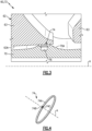
- the seal 74 can be a piston ring having a generally hoop-shaped geometry, as illustrated in Figure 4 .
- the seal 74 is a split ring including a main body 74A extending between opposed first and second ends 74B, 74C.
- the first end 74B engages with the second end 74C at an interface along the outer diameter portion 70A of the shaft 70.
- the body 74A is continuous to form a full hoop.
- the seal 74 is dimensioned to extend about a circumference of the shaft 70.
- the shaft 70 includes an annular groove 76 extending inwardly from the outer diameter portion 70A.
- the groove 76 is dimensioned to receive at least a portion of the seal 74.
- the seal 74 is seated in the groove 76 to establish a sealing relationship with an inner diameter portion 63A of the hub 63.
- the seal 74 can be arranged such that the first end 74B engages with the second end 74C along the outer diameter portion 70A of the shaft 70.
- the seal 74 can be exposed to relatively high temperatures due to proximity to the gas path GP and other portions of the engine 20.
- the seal 74 has a multi-layer construction including a substrate 78 and a coating 80 including a plurality of layers.
- the coating 80 can include at least a first layer 80A and a second layer 80B. At least a portion of the substrate 78 is seated in the groove 76, and the coating 80 is situated between the substrate 78 and the hub 63.
- the second layer 80B can define an external surface of the seal 74.
- the inner diameter portion 63A of the hub 63 defines a counter face or seal land.
- the second layer 80B can be dimensioned to abut against the hub 63 to establish a sealing relationship with the seal land.
- the second layer 80B is dimensioned and arranged to abut against or contact the inner diameter portion 63A of the hub 63, or is otherwise in close proximity to the seal land, to establish the sealing relationship with the hub 63 along an interface 84.
- the first layer 80A can be disposed directly on the substrate 78.
- the second layer 80B is disposed on the first layer 80A.
- one or more layers of material are formed between the substrate 78 and first layer 80A and/or between the first and second layers 80A, 80B.
- the hub 63 can include a third layer 86 (shown in dashed lines for illustrative purposes) disposed on surfaces of the inner diameter portion 63A along the interface 84 to establish the seal land. In other examples, the third layer 86 is omitted.
- the first layer 80A can be made of a first material
- the second layer 80B can be made of a second material
- the substrate 78 can be made of a third material.
- the first, second and/or third materials can differ in composition and/or construction.
- the substrate 78 and/or rotor 62 can comprise a high temperature metal or metal alloy, such as a nickel alloy.
- Example nickel alloys include nickel chromium alloy sold under the tradename INCONEL ® alloy 718 (IN718) and Direct Age Processed Alloy 718 (DA718).
- the substrate 78 is made of IN718 and at least the inner diameter portion 63A of the hub 63 is made of DA718.
- the substrate 78 comprises a cobalt alloy, e.g. a cobalt alloy sold under the tradename STELLITE ® 6B, and the first layer 80A can be omitted.
- the first layer 80A may be a relatively soft metal or metal alloy coating comprising copper or a copper alloy including aluminum or nickel, for example.
- the first layer 80A is a nickel-based or molybdenum-based metal or metal alloy.
- the first layer 80A has a composition, by weight percent, of about 60% to about 95% copper, and aluminum, e.g. the balance is aluminum.
- the first layer 80A has a composition, by weight percent, of about 85% to about 95% copper, and at least 5% aluminum.
- the first layer 80A has a composition, by weight percent, 8% to 12% aluminum, and at least 85% copper.
- the first layer 80A has a composition, by weight percent, of about 90% copper, and about 10% aluminum. In other examples, the first layer 80A has a composition of copper including any of the weight percentages disclosed herein, and the balance is aluminum or nickel. For the purposes of this disclosure, the term "about” means ⁇ 3% of the disclosed weight percent value unless otherwise stated.
- the second layer 80B can be a low friction coating comprising a solid lubricant.
- the second layer 80B can have a lesser hardness than the first layer 80A. Hardness of the layers 80A, 80B can be measured by means of nanoindentation.
- the first layer 80A of the coating 80 is a layer of copper alloy disposed on the substrate 78
- the second layer 80B is a solid lubricant disposed on the first layer 80A.
- a hardness of the copper-based coating can be relatively lower than other materials to reduce wear of the counter face and the solid lubricant that may otherwise occur due to the interface 84.
- the second layer 80B provides a self-lubricating feature and can reduce frictional heating along the interface 84.
- the solid lubricant of the second layer 80B includes molybdenum trioxide (MoO 3 ).
- the second layer 80B can be formed utilizing any of the techniques disclosed herein, including applying a solid lubricant such as molybdenum disulfide (MoS 2 ) on the first layer 80A or substrate 78 and heat treating the solid lubricant to form MoOs.
- the solid lubricant can reduce a coefficient of friction (COF) between the seal 74 and the rotor 62 along the interface 84, which can reduce wear and improve durability of the components of the rotor assembly 60, including the seal 74 and rotor 62.
- the second layer 80B can have a relatively lower COF than the first layer 80A of the coating 80.
- the third layer 86 of the hub 63 can be a solid lubricant, which can be the same or can differ from the solid lubricant of the second layer 80B.
- the solid lubricant of the third layer 86 can comprise MoS 2 , MoOs, boron nitride, tungsten disulfide, and carbon-based and graphite-based materials, for example. Applying a solid lubricant to the inner diameter portion 63A of the hub 63 can reduce leakage along the interface 84.
- the shaft 70 and each rotor 62 rotate as an assembly about the engine axis A.
- the seal 74 may move relative to the hub 63 along the interface 84 in axial, radial and/or circumferential directions X, R, C.
- the axial direction X can be coincidental or parallel to the engine axis A. Sliding or movement of the seal 74 along the interface 84 in the axial and/or circumferential directions X, C may occur due to relatively high vibratory energy in the system.
- the solid lubricant can reduce the COF and frictional heating along the interface 84, which can reduce galling and other wear along the adjacent surfaces and can increase durability of the seal 74 and the rotor 62. Reduced wear can reduce overhaul costs that may otherwise be associated with replacement or refurbishment of the seal 74, shaft 70 and/or rotor 62.
- Figures 6A and 6B illustrate example plots of COF versus cycles of rotor assemblies.
- the x-axis corresponds to the number of cycles of movement of the respective seal relative to the interface.
- the y-axis corresponds to the average COF. Values along the y-axis correspond to movement of the seal in a first direction.
- Figure 6A illustrates curve 88 corresponding to average COF values for a seal having a copper-based coating free of a solid lubricant.
- Figure 6B illustrates curve 90 corresponding to average COF values for the seal 74 having a copper-based coating and a MoOs-based solid lubricant.
- the MoOs-based solid lubricant can be formed from a MoOs-based solid lubricant utilizing any of the techniques disclosed herein.
- the copper-based coating including a MoOs-based solid lubricant can reduce the average COF as compared to coatings free of a solid lubricant.
- the seal 74 has an average COF of less than 0.4, such as less than 0.3 when the solid lubricant is first formed and between 0.3 and 0.35 subsequent to an initial break-in period of the seal 74, whereas the average COF of curve 88 is greater than 0.5 for a comparable number of cycles.
- the combination of materials of the substrate 78, layers 80A, 80B of coating 80 and/or hub 63 can reduce wear adjacent the first and second ends 74B, 74C of the seal 74 and adjacent portions of the hub 63.
- Figure 7 illustrates a process in a flowchart 92 for forming a rotor assembly, including any of the seals and rotor assemblies disclosed herein. Reference is made to the seal 74 and rotor assembly 60 of Figures 3-5 for illustrative purposes.
- a coating including one or more layers of material is removed from surfaces of substrate 78 at step 94, including at least a previously applied second layer 80B comprised of a solid lubricant.
- the first layer 80A is deposited or is otherwise disposed or formed on the substrate 78 at step 95.
- the first layer 80A can be formed on the substrate 78 utilizing various techniques, such as by plasma spray deposition or another thermal spraying technique.
- Example techniques for forming the first layer 80A can include physical vapor deposition (PVD) and chemical vapor deposition (CVD).
- step 94 includes removing a previously applied first layer 80A such as a layer of copper alloy from the substrate 78 prior to step 95.
- the previously applied first layer 80A may be removed after about 10,000-12,000 operating cycles of the engine, whereas a previously applied second layer 80B may be removed after a lesser number of operating cycles, such as approximately 1000 operating cycles, for example.
- the second layer 80B comprising a solid lubricant such as MoOs is disposed or otherwise formed on the first layer 80A.
- Step 96 can include depositing the second layer 80B directly on the first layer 80A.
- the third layer 86 comprising a solid lubricant is deposited or otherwise formed on the hub 63. A previously applied third layer 86 can be removed prior to steps 95, 96.
- the second and third layers 80B, 86 can be applied utilizing various techniques, such as brushing, swabbing, or spraying including any of the spraying techniques disclosed herein.
- the second and/or third layers 80B, 86 are applied by PVD or CVD techniques.
- Step 96 can include depositing a precursor on the first layer 80A at step 97, and heating the precursor to a predetermined temperature threshold for a predetermined time threshold to form the solid lubricant at step 98.
- the precursor is a solid lubricant such as MoS 2 and is applied by brushing, swabbing or spraying to obtain a thickness of about 0.000254-0.00254 cm (0.0001-0.001 inches) at step 97, for example, and step 98 includes forming a solid lubricant comprising MoOs in response to heating the precursor to a predetermined temperature threshold of at least about 399° C (750° F), including oxidation of the precursor such as MoS 2 .
- the MoS 2 or other solid lubricant can include a binder such as silicate.
- the MoS 2 applied to the first layer 80A at step 97 can be free of any MoO 3 . Forming the MoO 3 from MoS 2 can reduce manufacturing cost and complexity.
- step 98 includes pre-treating the coating 80 by heating the MoS 2 deposited on the substrate 78 or first layer 80A to about 499° C (930° F) for about 8 hours to form the second layer 80B of MoOs.
- the solid lubricant may comprise no more than about 10% of binder constituents such that a majority, such as at least 90%, of the second layer 80B is MoOs.
- the predetermined time threshold can be greater than about 8 hours to increase a concentration of the MoO 3 forming the second layer 80B.
- the first, second and/or third layers 80A, 80B, 86 may include one or more sublayers. One or more layers of material may be formed on and/or between the layers 80A, 80B, 86. Various finishing operations can be applied to the seal 74 once the respective layers 80A, 80B, 86 are formed.
Landscapes
- Engineering & Computer Science (AREA)
- General Engineering & Computer Science (AREA)
- Mechanical Engineering (AREA)
- Chemical & Material Sciences (AREA)
- Combustion & Propulsion (AREA)
- Ceramic Engineering (AREA)
- Structures Of Non-Positive Displacement Pumps (AREA)
Claims (15)
- Rotorbaugruppe (60, 60', 60") für ein Gasturbinentriebwerk (20), umfassend:einen Rotor (62), der eine Nabe (63) beinhaltet, die eine oder mehrere drehbare Schaufeln (64) trägt, wobei der Rotor (62) mechanisch an einer Welle (70) befestigt ist; undeine ringförmige Dichtung (74, 74', 74"), die durch die Welle (70) getragen wird, wobei die ringförmige Dichtung (74, 74', 74") Folgendes umfasst:ein Substrat (78);eine erste Schicht (80A), die auf dem Substrat (78) angeordnet ist; undeine zweite Schicht (80B), die auf der ersten Schicht (80A) angeordnet und eingerichtet ist, um eine abdichtende Beziehung mit dem Rotor (62) herzustellen,dadurch gekennzeichnet, dass die zweite Schicht (80B) ein festes Schmiermittel umfasst, das Molybdäntrioxid (MoO3) beinhaltet; undwobei der Rotor (62) ein einstückig beschaufelter Rotor ist.
- Rotorbaugruppe (60, 60', 60") nach Anspruch 1, wobei die erste Schicht (80A) Kupfer umfasst.
- Rotorbaugruppe (60, 60', 60") nach Anspruch 2, wobei die erste Schicht (80A) eine Zusammensetzung, in Gewichtsprozent, aus 60 % bis 95 % Kupfer und Aluminium aufweist, oder wobei die erste Schicht (80A) eine Zusammensetzung, in Gewichtsprozent, aus 8 % bis 12 % Aluminium und mindestens 85 % Kupfer aufweist, oder wobei die erste Schicht (80A) eine Zusammensetzung, in Gewichtsprozent, aus 85 % bis 95 % Kupfer und mindestens 5 % Aluminium aufweist.
- Rotorbaugruppe (60, 60', 60") nach einem der vorhergehenden Ansprüche, wobei das Substrat (78) eine Nickellegierung umfasst.
- Rotorbaugruppe (60, 60', 60") nach einem der vorhergehenden Ansprüche, wobei sich die ringförmige Dichtung (74, 74', 74") um einen Außendurchmesserteil (70A) der Welle (70) erstreckt, wobei der einstückig beschaufelte Rotor vorzugsweise ein Verdichterrotor ist und das Substrat (78) der ringförmigen Dichtung (74, 74', 74") in einer ringförmigen Nut (76) sitzt, die sich von dem Außendurchmesserteil (70A) der Welle (70) nach innen erstreckt, und die zweite Schicht (80B) an einem Innendurchmesserteil (63A) der Nabe (63) anliegt.
- Rotorbaugruppe (60, 60', 60") nach einem der vorhergehenden Ansprüche, wobei die ringförmige Dichtung (74, 74', 74") ein gespaltener Ring ist, der einen Dichtungskörper (74A) beinhaltet, der sich zwischen einem ersten Ende (74B) und einem zweiten, gegenüberliegenden Ende (74C) erstreckt, das mit dem ersten Ende (74B) in Eingriff steht.
- Rotorbaugruppe (60, 60', 60") nach einem der vorhergehenden Ansprüche, wobei das Molybdäntrioxid (MoO3) aus Molybdändisulfid (MoS2) ausgebildet ist.
- Gasturbinentriebwerk (20), umfassend:einen Gebläseabschnitt (22), der ein Gebläse (42) beinhaltet;einen Verdichterabschnitt (24), der einen Verdichter (44, 52) beinhaltet;einen Turbinenabschnitt (28), der eine mit dem Verdichter (44, 52) gekoppelte Turbine (46, 54) beinhaltet;eine Welle (70), die um eine Triebwerkslängsachse drehbar ist; undwobei der Verdichterabschnitt (24) eine Rotorbaugruppe nach einem der Ansprüche 1-7 beinhaltet.
- Gasturbinentriebwerk (20) nach Anspruch 8, wobei der Verdichterabschnitt (24) einen Niederdruckverdichter (44) und einen Hochdruckverdichter (52) beinhaltet und der einstückig beschaufelte Rotor ein Hochdruckverdichterrotor des Hochdruckverdichters (52) ist.
- Verfahren zum Abdichten für ein Gasturbinentriebwerk (20), umfassend:Ausbilden eines Kolbenrings (74, 74', 74"), umfassend eine erste Schicht (80A), die auf einem Substrat (78) angeordnet ist, und eine zweite Schicht (80B), die auf der ersten Schicht (80A) angeordnet ist; undmechanisches Befestigen eines Rotors (62) derart an einer drehbaren Welle (70), dass der Kolbenring (74, 74', 74") eine abdichtende Beziehung zwischen dem Rotor (62) und der Welle (70) herstellt, wobei der Rotor (62) eine Nabe (63) beinhaltet, die eine oder mehrere drehbare Schaufeln (64) trägt; wobei das Verfahren dadurch gekennzeichnet ist, dass die zweite Schicht (80B) ein festes Schmiermittel umfasst, das Molybdäntrioxid (MoO3) beinhaltet; und wobeider Rotor (62) ein einstückig beschaufelter Rotor ist.
- Verfahren nach Anspruch 10, wobei der Schritt des Ausbildens das Abscheiden der zweiten Schicht (80B) direkt auf der ersten Schicht (80A) beinhaltet und/oder wobei der Schritt des Ausbildens das Abscheiden von Molybdändisulfid (MoS2) auf der ersten Schicht (80A) und das Erhitzen des Molybdändisulfids (MoS2) auf eine vorbestimmte Temperaturschwelle beinhaltet, um das feste Schmiermittel auszubilden.
- Verfahren nach Anspruch 10 oder Anspruch 11, wobei die erste Schicht (80A) eine Zusammensetzung, in Gewichtsprozent, aus 85 % bis 95 % Kupfer und mindestens 5 % Aluminium aufweist.
- Verfahren nach einem der Ansprüche 10 bis 12, wobei der Kolbenring (74, 74', 74") einen Dichtungskörper (74A) beinhaltet, der sich zwischen einem ersten Ende (74B) und einem zweiten, gegenüberliegenden Ende (74C) erstreckt, das mit dem ersten Ende (74B) entlang eines Außendurchmesserteils (70A) der Welle (70) in Eingriff steht.
- Verfahren nach einem der Ansprüche 10 bis 13, wobei die Nabe (63) einen Dichtungssteg ausbildet, der die abdichtende Beziehung mit der zweiten Schicht (80B) herstellt.
- Verfahren nach einem der Ansprüche 10-14, wobei:
die zweite Schicht (80B) so bemessen ist, dass sie an einem Innendurchmesserteil (63A) der Nabe (63) anliegt, um die abdichtende Beziehung herzustellen.
Applications Claiming Priority (1)
| Application Number | Priority Date | Filing Date | Title |
|---|---|---|---|
| US16/534,154 US11149651B2 (en) | 2019-08-07 | 2019-08-07 | Seal ring assembly for a gas turbine engine |
Publications (2)
| Publication Number | Publication Date |
|---|---|
| EP3783201A1 EP3783201A1 (de) | 2021-02-24 |
| EP3783201B1 true EP3783201B1 (de) | 2024-12-11 |
Family
ID=71786873
Family Applications (1)
| Application Number | Title | Priority Date | Filing Date |
|---|---|---|---|
| EP20187768.5A Active EP3783201B1 (de) | 2019-08-07 | 2020-07-24 | Rotoranordnung für ein gasturbinentriebwerk und zugehöriges dichtungsverfahren |
Country Status (2)
| Country | Link |
|---|---|
| US (1) | US11149651B2 (de) |
| EP (1) | EP3783201B1 (de) |
Families Citing this family (11)
| Publication number | Priority date | Publication date | Assignee | Title |
|---|---|---|---|---|
| US20240360764A1 (en) * | 2022-10-07 | 2024-10-31 | Hamilton Sundstrand Corporation | Impeller preloading bands |
| US20240151152A1 (en) * | 2022-11-08 | 2024-05-09 | Raytheon Technologies Corporation | Seal for gas turbine engine |
| US12352173B2 (en) * | 2022-11-25 | 2025-07-08 | Rtx Corporation | Gas turbine engine with carbon/carbon composite piston seal |
| US20240200659A1 (en) * | 2022-12-15 | 2024-06-20 | Raytheon Technologies Corporation | Gas turbine engine with split helical piston seal |
| US12448923B2 (en) * | 2023-03-13 | 2025-10-21 | Rtx Corporation | Protective treatment and method of applying the same |
| US12188563B2 (en) * | 2023-03-30 | 2025-01-07 | Rtx Corporation | Mistake-proofing for hydrostatic seal assemblies |
| US12392251B2 (en) | 2023-07-06 | 2025-08-19 | Rtx Corporation | Diametrically expandable/collapsible piston seal |
| US12228032B1 (en) * | 2023-10-17 | 2025-02-18 | Rtx Corporation | Metallic seal |
| US12510154B2 (en) | 2024-01-04 | 2025-12-30 | Rtx Corporation | Light weight hybrid piston seal ring |
| WO2025151862A1 (en) * | 2024-01-12 | 2025-07-17 | Rtx Corporation | Laser texturing of piston seal rings |
| US12503954B2 (en) * | 2024-06-14 | 2025-12-23 | Rtx Corporation | Center-tie shaft tensioning |
Citations (2)
| Publication number | Priority date | Publication date | Assignee | Title |
|---|---|---|---|---|
| US20070031651A1 (en) * | 2005-08-08 | 2007-02-08 | Daido Metal Company Ltd. | Slide bearing for internal combustion engines |
| EP2453150A1 (de) * | 2010-11-10 | 2012-05-16 | United Technologies Corporation | Dichtungsanordnung |
Family Cites Families (44)
| Publication number | Priority date | Publication date | Assignee | Title |
|---|---|---|---|---|
| GB1103479A (en) * | 1966-11-24 | 1968-02-14 | Rolls Royce | Fluid seal device |
| US3534652A (en) * | 1967-10-02 | 1970-10-20 | Marlo Co Inc | Braided high-temperature packing |
| GB1320554A (en) | 1969-10-02 | 1973-06-13 | American Metal Climax Inc | Oxidation of molybdenum sulphide |
| IT1025260B (it) | 1973-11-16 | 1978-08-10 | Mtu Muenchen Gmbh | Turbina a raffreddamento interno della corona e con posizioni prescritte di rottura |
| US3847506A (en) | 1973-11-29 | 1974-11-12 | Avco Corp | Turbomachine rotor |
| US4456538A (en) * | 1980-02-01 | 1984-06-26 | The Lubrizol Corporation | Process for preparing molybdenum-containing compositions useful for improved fuel economy of internal combustion engines |
| US4536932A (en) | 1982-11-22 | 1985-08-27 | United Technologies Corporation | Method for eliminating low cycle fatigue cracking in integrally bladed disks |
| US4875830A (en) | 1985-07-18 | 1989-10-24 | United Technologies Corporation | Flanged ladder seal |
| FR2603947B1 (fr) * | 1986-09-17 | 1990-11-30 | Snecma | Dispositif de maintien d'un joint d'etancheite sur un bout d'arbre et turbomachine le comportant |
| US4871266A (en) * | 1987-06-24 | 1989-10-03 | Ngk Insulators, Ltd. | Slide assemblies |
| US5292138A (en) * | 1992-09-21 | 1994-03-08 | General Elecric Company | Rotor to rotor split ring seal |
| US5282985A (en) * | 1993-06-24 | 1994-02-01 | The United States Of America As Represented By The Secretary Of The Air Force | Lubricant coatings |
| US5632600A (en) | 1995-12-22 | 1997-05-27 | General Electric Company | Reinforced rotor disk assembly |
| JPH10183327A (ja) | 1996-10-28 | 1998-07-14 | Nippon Piston Ring Co Ltd | 摺動部材のなじみ性溶射被膜層 |
| JP4023872B2 (ja) * | 1997-06-26 | 2007-12-19 | 大豊工業株式会社 | 斜板式コンプレッサー用斜板 |
| US5988980A (en) | 1997-09-08 | 1999-11-23 | General Electric Company | Blade assembly with splitter shroud |
| US5804151A (en) * | 1997-09-16 | 1998-09-08 | Cyprus Amax Minerals Company | Process for autoclaving molybdenum disulfide |
| US6422818B2 (en) | 1998-08-07 | 2002-07-23 | General Electric Company | Lubricating system for thermal medium delivery parts in a gas turbine |
| US6655695B1 (en) * | 2001-02-13 | 2003-12-02 | Honeywell International Inc. | Face seal assembly with composite rotor |
| US7021042B2 (en) | 2002-12-13 | 2006-04-04 | United Technologies Corporation | Geartrain coupling for a turbofan engine |
| US7510760B2 (en) * | 2005-03-07 | 2009-03-31 | Boardof Trustees Of The University Of Arkansas | Nanoparticle compositions, coatings and articles made therefrom, methods of making and using said compositions, coatings and articles |
| JP2007023352A (ja) | 2005-07-19 | 2007-02-01 | Ishikawajima Harima Heavy Ind Co Ltd | 皮膜形成方法 |
| KR100849075B1 (ko) * | 2006-08-29 | 2008-07-30 | 한국과학기술연구원 | 고속 터보 기기의 무급유 베어링용 중온 코팅제 및 그 코팅방법 |
| AU2007319146A1 (en) | 2006-11-16 | 2008-05-22 | Albemarle Netherlands B.V. | Purification of molybdenum technical oxide |
| US7887299B2 (en) | 2007-06-07 | 2011-02-15 | Honeywell International Inc. | Rotary body for turbo machinery with mistuned blades |
| US9133720B2 (en) | 2007-12-28 | 2015-09-15 | United Technologies Corporation | Integrally bladed rotor with slotted outer rim |
| US9273563B2 (en) | 2007-12-28 | 2016-03-01 | United Technologies Corporation | Integrally bladed rotor with slotted outer rim |
| US20170284083A1 (en) * | 2008-11-20 | 2017-10-05 | Emseal Joint Systems Ltd. | Coiled precompressed, precoated joint seal and method of making |
| US20140151968A1 (en) * | 2012-11-21 | 2014-06-05 | Emseal Joint Systems Ltd. | Coiled precompressed, precoated joint seal and method of making |
| DE102009007468A1 (de) | 2009-02-04 | 2010-08-19 | Mtu Aero Engines Gmbh | Integral beschaufelte Rotorscheibe für eine Turbine |
| US8157514B2 (en) | 2009-03-19 | 2012-04-17 | Honeywell International Inc. | Components for gas turbine engines |
| DE102009053954A1 (de) * | 2009-11-19 | 2011-06-09 | Siemens Aktiengesellschaft | Labyrinthdichtung und Verfahren zum Herstellen einer Labyrinthdichtung |
| DE102010053751A1 (de) * | 2010-10-28 | 2012-05-03 | Oerlikon Trading Ag, Trübbach | Molybdänmonoxidschichten und deren Herstellung mittels PVD |
| EP2520764A1 (de) | 2011-05-02 | 2012-11-07 | MTU Aero Engines GmbH | Schaufel mit gekühltem Schaufelfuss |
| EP2520768A1 (de) | 2011-05-02 | 2012-11-07 | MTU Aero Engines AG | Dichteinrichtung für einen integral beschaufelten Rotorgrundkörper einer Strömungsmaschine |
| US8939710B2 (en) * | 2011-08-24 | 2015-01-27 | United Technologies Corporation | Rotating turbomachine seal |
| US10396365B2 (en) * | 2012-07-18 | 2019-08-27 | Printed Energy Pty Ltd | Diatomaceous energy storage devices |
| US9994785B2 (en) | 2014-04-02 | 2018-06-12 | Rolls-Royce Corporation | Thermally stable self-lubricating coatings |
| GB201506197D0 (en) | 2015-04-13 | 2015-05-27 | Rolls Royce Plc | Rotor damper |
| US10006466B2 (en) | 2015-04-13 | 2018-06-26 | United Technologies Corporation | Clamped HPC seal ring |
| US10550726B2 (en) * | 2017-01-30 | 2020-02-04 | General Electric Company | Turbine spider frame with additive core |
| JP6764381B2 (ja) * | 2017-08-24 | 2020-09-30 | 三菱重工業株式会社 | 軸シール構造および一次冷却材循環ポンプ |
| US20190186281A1 (en) * | 2017-12-20 | 2019-06-20 | United Technologies Corporation | Compressor abradable seal with improved solid lubricant retention |
| US10920617B2 (en) | 2018-08-17 | 2021-02-16 | Raytheon Technologies Corporation | Gas turbine engine seal ring assembly |
-
2019
- 2019-08-07 US US16/534,154 patent/US11149651B2/en active Active
-
2020
- 2020-07-24 EP EP20187768.5A patent/EP3783201B1/de active Active
Patent Citations (2)
| Publication number | Priority date | Publication date | Assignee | Title |
|---|---|---|---|---|
| US20070031651A1 (en) * | 2005-08-08 | 2007-02-08 | Daido Metal Company Ltd. | Slide bearing for internal combustion engines |
| EP2453150A1 (de) * | 2010-11-10 | 2012-05-16 | United Technologies Corporation | Dichtungsanordnung |
Also Published As
| Publication number | Publication date |
|---|---|
| US11149651B2 (en) | 2021-10-19 |
| US20210040892A1 (en) | 2021-02-11 |
| EP3783201A1 (de) | 2021-02-24 |
Similar Documents
| Publication | Publication Date | Title |
|---|---|---|
| EP3783201B1 (de) | Rotoranordnung für ein gasturbinentriebwerk und zugehöriges dichtungsverfahren | |
| EP3611348B1 (de) | Dichtungsringanordnung für gasturbinentriebwerk | |
| EP3819475B1 (de) | Äussere laufschaufelluftdichtungsanordnung und verfahren zur abdichtung | |
| EP3650657B1 (de) | Dichtungsanordnung mit pralldichtungsplatte | |
| EP3613950B1 (de) | Aus laminat geformte schaufelaussenluftdichtung mit radialen stützhaken | |
| US10145245B2 (en) | Bonded multi-piece gas turbine engine component | |
| US10385719B2 (en) | Variable vane bushing | |
| EP3587740B1 (de) | Dichtungsanordnung für ein gasturbinentriebwerk und montageverfahren | |
| EP3892822B1 (de) | Leitschaufelträgersystem | |
| EP4063619A1 (de) | Aussendeckband für einen gas turbinenmotor | |
| EP3323999B1 (de) | Endwandbogensegmente mit abdeckung über verbindungsstelle | |
| EP2987960B1 (de) | Keramikbeschichtungssystem und -verfahren | |
| EP3196419A1 (de) | Äussere laufschaufelluftdichtung mit einer oberflächenschicht mit taschen | |
| EP3819464B1 (de) | Schaufel mit dichtung und halteplatte | |
| EP4379192A1 (de) | Dichtungsnut mit beschichtung | |
| EP4253726B1 (de) | Cmc-schaufelverbindungs-flansche mit durch schichten verlaufenden dichtungsschlitzen | |
| EP4086433B1 (de) | Dichtungsanordnung mit dichtungsbogensegment | |
| EP4086435B1 (de) | Maschinell bearbeitbare beschichtung mit variabler dicke für plattformdichtungen | |
| US20230212950A1 (en) | Bathtub damper seal arrangement for gas turbine engine | |
| EP4047189A1 (de) | Berührungslose dichtungsanordnung mit innenbeschichtung | |
| EP3608512B1 (de) | Gasturbinentriebwerk mit dichtfläche für schaufelaussendichtung | |
| EP4431705A1 (de) | Kohlenstoff- /kohlenstoffverbundwerkstoffkolbendichtung zwischen schaft und rotor eines gasturbinenmotors und herstellungsverfahren | |
| WO2015123268A1 (en) | System and method for applying a metallic coating | |
| EP4080018B1 (de) | Schaufelbogensegment mit flansch mit stufe und verfahren zur herstellung eines schaufelbogensegments | |
| EP4403748A1 (de) | Dichtung zwischen keramischer und metallischer komponente eines gasturbinenmotors |
Legal Events
| Date | Code | Title | Description |
|---|---|---|---|
| PUAI | Public reference made under article 153(3) epc to a published international application that has entered the european phase |
Free format text: ORIGINAL CODE: 0009012 |
|
| STAA | Information on the status of an ep patent application or granted ep patent |
Free format text: STATUS: THE APPLICATION HAS BEEN PUBLISHED |
|
| AK | Designated contracting states |
Kind code of ref document: A1 Designated state(s): AL AT BE BG CH CY CZ DE DK EE ES FI FR GB GR HR HU IE IS IT LI LT LU LV MC MK MT NL NO PL PT RO RS SE SI SK SM TR |
|
| AX | Request for extension of the european patent |
Extension state: BA ME |
|
| STAA | Information on the status of an ep patent application or granted ep patent |
Free format text: STATUS: REQUEST FOR EXAMINATION WAS MADE |
|
| 17P | Request for examination filed |
Effective date: 20210819 |
|
| RBV | Designated contracting states (corrected) |
Designated state(s): AL AT BE BG CH CY CZ DE DK EE ES FI FR GB GR HR HU IE IS IT LI LT LU LV MC MK MT NL NO PL PT RO RS SE SI SK SM TR |
|
| STAA | Information on the status of an ep patent application or granted ep patent |
Free format text: STATUS: EXAMINATION IS IN PROGRESS |
|
| 17Q | First examination report despatched |
Effective date: 20220801 |
|
| RAP3 | Party data changed (applicant data changed or rights of an application transferred) |
Owner name: RTX CORPORATION |
|
| GRAP | Despatch of communication of intention to grant a patent |
Free format text: ORIGINAL CODE: EPIDOSNIGR1 |
|
| STAA | Information on the status of an ep patent application or granted ep patent |
Free format text: STATUS: GRANT OF PATENT IS INTENDED |
|
| RIC1 | Information provided on ipc code assigned before grant |
Ipc: F16J 15/44 20060101ALI20240108BHEP Ipc: F16J 9/26 20060101ALI20240108BHEP Ipc: F16J 15/00 20060101ALI20240108BHEP Ipc: F16J 1/00 20060101ALI20240108BHEP Ipc: F01D 11/00 20060101AFI20240108BHEP |
|
| INTG | Intention to grant announced |
Effective date: 20240209 |
|
| GRAJ | Information related to disapproval of communication of intention to grant by the applicant or resumption of examination proceedings by the epo deleted |
Free format text: ORIGINAL CODE: EPIDOSDIGR1 |
|
| STAA | Information on the status of an ep patent application or granted ep patent |
Free format text: STATUS: EXAMINATION IS IN PROGRESS |
|
| INTC | Intention to grant announced (deleted) | ||
| GRAP | Despatch of communication of intention to grant a patent |
Free format text: ORIGINAL CODE: EPIDOSNIGR1 |
|
| STAA | Information on the status of an ep patent application or granted ep patent |
Free format text: STATUS: GRANT OF PATENT IS INTENDED |
|
| INTG | Intention to grant announced |
Effective date: 20240704 |
|
| GRAS | Grant fee paid |
Free format text: ORIGINAL CODE: EPIDOSNIGR3 |
|
| GRAA | (expected) grant |
Free format text: ORIGINAL CODE: 0009210 |
|
| STAA | Information on the status of an ep patent application or granted ep patent |
Free format text: STATUS: THE PATENT HAS BEEN GRANTED |
|
| AK | Designated contracting states |
Kind code of ref document: B1 Designated state(s): AL AT BE BG CH CY CZ DE DK EE ES FI FR GB GR HR HU IE IS IT LI LT LU LV MC MK MT NL NO PL PT RO RS SE SI SK SM TR |
|
| REG | Reference to a national code |
Ref country code: GB Ref legal event code: FG4D |
|
| REG | Reference to a national code |
Ref country code: CH Ref legal event code: EP |
|
| REG | Reference to a national code |
Ref country code: IE Ref legal event code: FG4D |
|
| REG | Reference to a national code |
Ref country code: DE Ref legal event code: R096 Ref document number: 602020042869 Country of ref document: DE |
|
| REG | Reference to a national code |
Ref country code: LT Ref legal event code: MG9D |
|
| PG25 | Lapsed in a contracting state [announced via postgrant information from national office to epo] |
Ref country code: HR Free format text: LAPSE BECAUSE OF FAILURE TO SUBMIT A TRANSLATION OF THE DESCRIPTION OR TO PAY THE FEE WITHIN THE PRESCRIBED TIME-LIMIT Effective date: 20241211 |
|
| PG25 | Lapsed in a contracting state [announced via postgrant information from national office to epo] |
Ref country code: FI Free format text: LAPSE BECAUSE OF FAILURE TO SUBMIT A TRANSLATION OF THE DESCRIPTION OR TO PAY THE FEE WITHIN THE PRESCRIBED TIME-LIMIT Effective date: 20241211 |
|
| PG25 | Lapsed in a contracting state [announced via postgrant information from national office to epo] |
Ref country code: BG Free format text: LAPSE BECAUSE OF FAILURE TO SUBMIT A TRANSLATION OF THE DESCRIPTION OR TO PAY THE FEE WITHIN THE PRESCRIBED TIME-LIMIT Effective date: 20241211 |
|
| REG | Reference to a national code |
Ref country code: NL Ref legal event code: MP Effective date: 20241211 |
|
| PG25 | Lapsed in a contracting state [announced via postgrant information from national office to epo] |
Ref country code: ES Free format text: LAPSE BECAUSE OF FAILURE TO SUBMIT A TRANSLATION OF THE DESCRIPTION OR TO PAY THE FEE WITHIN THE PRESCRIBED TIME-LIMIT Effective date: 20241211 |
|
| PG25 | Lapsed in a contracting state [announced via postgrant information from national office to epo] |
Ref country code: NO Free format text: LAPSE BECAUSE OF FAILURE TO SUBMIT A TRANSLATION OF THE DESCRIPTION OR TO PAY THE FEE WITHIN THE PRESCRIBED TIME-LIMIT Effective date: 20250311 |
|
| PG25 | Lapsed in a contracting state [announced via postgrant information from national office to epo] |
Ref country code: GR Free format text: LAPSE BECAUSE OF FAILURE TO SUBMIT A TRANSLATION OF THE DESCRIPTION OR TO PAY THE FEE WITHIN THE PRESCRIBED TIME-LIMIT Effective date: 20250312 Ref country code: LV Free format text: LAPSE BECAUSE OF FAILURE TO SUBMIT A TRANSLATION OF THE DESCRIPTION OR TO PAY THE FEE WITHIN THE PRESCRIBED TIME-LIMIT Effective date: 20241211 |
|
| PG25 | Lapsed in a contracting state [announced via postgrant information from national office to epo] |
Ref country code: RS Free format text: LAPSE BECAUSE OF FAILURE TO SUBMIT A TRANSLATION OF THE DESCRIPTION OR TO PAY THE FEE WITHIN THE PRESCRIBED TIME-LIMIT Effective date: 20250311 |
|
| PG25 | Lapsed in a contracting state [announced via postgrant information from national office to epo] |
Ref country code: NL Free format text: LAPSE BECAUSE OF FAILURE TO SUBMIT A TRANSLATION OF THE DESCRIPTION OR TO PAY THE FEE WITHIN THE PRESCRIBED TIME-LIMIT Effective date: 20241211 |
|
| REG | Reference to a national code |
Ref country code: AT Ref legal event code: MK05 Ref document number: 1750522 Country of ref document: AT Kind code of ref document: T Effective date: 20241211 |
|
| PG25 | Lapsed in a contracting state [announced via postgrant information from national office to epo] |
Ref country code: SM Free format text: LAPSE BECAUSE OF FAILURE TO SUBMIT A TRANSLATION OF THE DESCRIPTION OR TO PAY THE FEE WITHIN THE PRESCRIBED TIME-LIMIT Effective date: 20241211 |
|
| PG25 | Lapsed in a contracting state [announced via postgrant information from national office to epo] |
Ref country code: PL Free format text: LAPSE BECAUSE OF FAILURE TO SUBMIT A TRANSLATION OF THE DESCRIPTION OR TO PAY THE FEE WITHIN THE PRESCRIBED TIME-LIMIT Effective date: 20241211 |
|
| PGFP | Annual fee paid to national office [announced via postgrant information from national office to epo] |
Ref country code: GB Payment date: 20250619 Year of fee payment: 6 |
|
| PG25 | Lapsed in a contracting state [announced via postgrant information from national office to epo] |
Ref country code: IS Free format text: LAPSE BECAUSE OF FAILURE TO SUBMIT A TRANSLATION OF THE DESCRIPTION OR TO PAY THE FEE WITHIN THE PRESCRIBED TIME-LIMIT Effective date: 20250411 |
|
| PG25 | Lapsed in a contracting state [announced via postgrant information from national office to epo] |
Ref country code: PT Free format text: LAPSE BECAUSE OF FAILURE TO SUBMIT A TRANSLATION OF THE DESCRIPTION OR TO PAY THE FEE WITHIN THE PRESCRIBED TIME-LIMIT Effective date: 20250411 |
|
| PG25 | Lapsed in a contracting state [announced via postgrant information from national office to epo] |
Ref country code: EE Free format text: LAPSE BECAUSE OF FAILURE TO SUBMIT A TRANSLATION OF THE DESCRIPTION OR TO PAY THE FEE WITHIN THE PRESCRIBED TIME-LIMIT Effective date: 20241211 |
|
| PGFP | Annual fee paid to national office [announced via postgrant information from national office to epo] |
Ref country code: FR Payment date: 20250619 Year of fee payment: 6 |
|
| PG25 | Lapsed in a contracting state [announced via postgrant information from national office to epo] |
Ref country code: RO Free format text: LAPSE BECAUSE OF FAILURE TO SUBMIT A TRANSLATION OF THE DESCRIPTION OR TO PAY THE FEE WITHIN THE PRESCRIBED TIME-LIMIT Effective date: 20241211 Ref country code: AT Free format text: LAPSE BECAUSE OF FAILURE TO SUBMIT A TRANSLATION OF THE DESCRIPTION OR TO PAY THE FEE WITHIN THE PRESCRIBED TIME-LIMIT Effective date: 20241211 |
|
| PG25 | Lapsed in a contracting state [announced via postgrant information from national office to epo] |
Ref country code: SK Free format text: LAPSE BECAUSE OF FAILURE TO SUBMIT A TRANSLATION OF THE DESCRIPTION OR TO PAY THE FEE WITHIN THE PRESCRIBED TIME-LIMIT Effective date: 20241211 |
|
| PG25 | Lapsed in a contracting state [announced via postgrant information from national office to epo] |
Ref country code: CZ Free format text: LAPSE BECAUSE OF FAILURE TO SUBMIT A TRANSLATION OF THE DESCRIPTION OR TO PAY THE FEE WITHIN THE PRESCRIBED TIME-LIMIT Effective date: 20241211 |
|
| PG25 | Lapsed in a contracting state [announced via postgrant information from national office to epo] |
Ref country code: IT Free format text: LAPSE BECAUSE OF FAILURE TO SUBMIT A TRANSLATION OF THE DESCRIPTION OR TO PAY THE FEE WITHIN THE PRESCRIBED TIME-LIMIT Effective date: 20241211 |
|
| PG25 | Lapsed in a contracting state [announced via postgrant information from national office to epo] |
Ref country code: SE Free format text: LAPSE BECAUSE OF FAILURE TO SUBMIT A TRANSLATION OF THE DESCRIPTION OR TO PAY THE FEE WITHIN THE PRESCRIBED TIME-LIMIT Effective date: 20241211 |
|
| REG | Reference to a national code |
Ref country code: DE Ref legal event code: R097 Ref document number: 602020042869 Country of ref document: DE |
|
| PG25 | Lapsed in a contracting state [announced via postgrant information from national office to epo] |
Ref country code: DK Free format text: LAPSE BECAUSE OF FAILURE TO SUBMIT A TRANSLATION OF THE DESCRIPTION OR TO PAY THE FEE WITHIN THE PRESCRIBED TIME-LIMIT Effective date: 20241211 |
|
| PGFP | Annual fee paid to national office [announced via postgrant information from national office to epo] |
Ref country code: DE Payment date: 20250620 Year of fee payment: 6 |
|
| PLBE | No opposition filed within time limit |
Free format text: ORIGINAL CODE: 0009261 |
|
| STAA | Information on the status of an ep patent application or granted ep patent |
Free format text: STATUS: NO OPPOSITION FILED WITHIN TIME LIMIT |
|
| 26N | No opposition filed |
Effective date: 20250912 |