EP3783173B1 - A vehicle door comprising a power child lock device - Google Patents
A vehicle door comprising a power child lock device Download PDFInfo
- Publication number
- EP3783173B1 EP3783173B1 EP19208492.9A EP19208492A EP3783173B1 EP 3783173 B1 EP3783173 B1 EP 3783173B1 EP 19208492 A EP19208492 A EP 19208492A EP 3783173 B1 EP3783173 B1 EP 3783173B1
- Authority
- EP
- European Patent Office
- Prior art keywords
- lever
- power child
- switch
- inside handle
- pin
- Prior art date
- Legal status (The legal status is an assumption and is not a legal conclusion. Google has not performed a legal analysis and makes no representation as to the accuracy of the status listed.)
- Active
Links
Images



Classifications
-
- E—FIXED CONSTRUCTIONS
- E05—LOCKS; KEYS; WINDOW OR DOOR FITTINGS; SAFES
- E05B—LOCKS; ACCESSORIES THEREFOR; HANDCUFFS
- E05B77/00—Vehicle locks characterised by special functions or purposes
- E05B77/22—Functions related to actuation of locks from the passenger compartment of the vehicle
- E05B77/24—Functions related to actuation of locks from the passenger compartment of the vehicle preventing use of an inner door handle, sill button, lock knob or the like
- E05B77/26—Functions related to actuation of locks from the passenger compartment of the vehicle preventing use of an inner door handle, sill button, lock knob or the like specially adapted for child safety
-
- E—FIXED CONSTRUCTIONS
- E05—LOCKS; KEYS; WINDOW OR DOOR FITTINGS; SAFES
- E05B—LOCKS; ACCESSORIES THEREFOR; HANDCUFFS
- E05B79/00—Mounting or connecting vehicle locks or parts thereof
- E05B79/10—Connections between movable lock parts
- E05B79/20—Connections between movable lock parts using flexible connections, e.g. Bowden cables
-
- E—FIXED CONSTRUCTIONS
- E05—LOCKS; KEYS; WINDOW OR DOOR FITTINGS; SAFES
- E05B—LOCKS; ACCESSORIES THEREFOR; HANDCUFFS
- E05B79/00—Mounting or connecting vehicle locks or parts thereof
- E05B79/10—Connections between movable lock parts
- E05B79/22—Operative connections between handles, sill buttons or lock knobs and the lock unit
-
- E—FIXED CONSTRUCTIONS
- E05—LOCKS; KEYS; WINDOW OR DOOR FITTINGS; SAFES
- E05B—LOCKS; ACCESSORIES THEREFOR; HANDCUFFS
- E05B81/00—Power-actuated vehicle locks
- E05B81/02—Power-actuated vehicle locks characterised by the type of actuators used
- E05B81/04—Electrical
- E05B81/06—Electrical using rotary motors
-
- E—FIXED CONSTRUCTIONS
- E05—LOCKS; KEYS; WINDOW OR DOOR FITTINGS; SAFES
- E05B—LOCKS; ACCESSORIES THEREFOR; HANDCUFFS
- E05B81/00—Power-actuated vehicle locks
- E05B81/12—Power-actuated vehicle locks characterised by the function or purpose of the powered actuators
- E05B81/16—Power-actuated vehicle locks characterised by the function or purpose of the powered actuators operating on locking elements for locking or unlocking action
-
- E—FIXED CONSTRUCTIONS
- E05—LOCKS; KEYS; WINDOW OR DOOR FITTINGS; SAFES
- E05B—LOCKS; ACCESSORIES THEREFOR; HANDCUFFS
- E05B81/00—Power-actuated vehicle locks
- E05B81/24—Power-actuated vehicle locks characterised by constructional features of the actuator or the power transmission
- E05B81/32—Details of the actuator transmission
- E05B81/34—Details of the actuator transmission of geared transmissions
-
- E—FIXED CONSTRUCTIONS
- E05—LOCKS; KEYS; WINDOW OR DOOR FITTINGS; SAFES
- E05B—LOCKS; ACCESSORIES THEREFOR; HANDCUFFS
- E05B81/00—Power-actuated vehicle locks
- E05B81/24—Power-actuated vehicle locks characterised by constructional features of the actuator or the power transmission
- E05B81/32—Details of the actuator transmission
- E05B81/40—Nuts or nut-like elements moving along a driven threaded axle
-
- E—FIXED CONSTRUCTIONS
- E05—LOCKS; KEYS; WINDOW OR DOOR FITTINGS; SAFES
- E05B—LOCKS; ACCESSORIES THEREFOR; HANDCUFFS
- E05B81/00—Power-actuated vehicle locks
- E05B81/54—Electrical circuits
- E05B81/64—Monitoring or sensing, e.g. by using switches or sensors
-
- E—FIXED CONSTRUCTIONS
- E05—LOCKS; KEYS; WINDOW OR DOOR FITTINGS; SAFES
- E05B—LOCKS; ACCESSORIES THEREFOR; HANDCUFFS
- E05B81/00—Power-actuated vehicle locks
- E05B81/54—Electrical circuits
- E05B81/64—Monitoring or sensing, e.g. by using switches or sensors
- E05B81/72—Monitoring or sensing, e.g. by using switches or sensors the lock status, i.e. locked or unlocked condition
-
- E—FIXED CONSTRUCTIONS
- E05—LOCKS; KEYS; WINDOW OR DOOR FITTINGS; SAFES
- E05B—LOCKS; ACCESSORIES THEREFOR; HANDCUFFS
- E05B85/00—Details of vehicle locks not provided for in groups E05B77/00 - E05B83/00
-
- F—MECHANICAL ENGINEERING; LIGHTING; HEATING; WEAPONS; BLASTING
- F16—ENGINEERING ELEMENTS AND UNITS; GENERAL MEASURES FOR PRODUCING AND MAINTAINING EFFECTIVE FUNCTIONING OF MACHINES OR INSTALLATIONS; THERMAL INSULATION IN GENERAL
- F16H—GEARING
- F16H55/00—Elements with teeth or friction surfaces for conveying motion; Worms, pulleys or sheaves for gearing mechanisms
- F16H55/02—Toothed members; Worms
- F16H55/22—Toothed members; Worms for transmissions with crossing shafts, especially worms, worm-gears
-
- E—FIXED CONSTRUCTIONS
- E05—LOCKS; KEYS; WINDOW OR DOOR FITTINGS; SAFES
- E05B—LOCKS; ACCESSORIES THEREFOR; HANDCUFFS
- E05B65/00—Locks or fastenings for special use
- E05B65/0014—Locks or fastenings for special use to prevent opening by children
-
- Y—GENERAL TAGGING OF NEW TECHNOLOGICAL DEVELOPMENTS; GENERAL TAGGING OF CROSS-SECTIONAL TECHNOLOGIES SPANNING OVER SEVERAL SECTIONS OF THE IPC; TECHNICAL SUBJECTS COVERED BY FORMER USPC CROSS-REFERENCE ART COLLECTIONS [XRACs] AND DIGESTS
- Y10—TECHNICAL SUBJECTS COVERED BY FORMER USPC
- Y10T—TECHNICAL SUBJECTS COVERED BY FORMER US CLASSIFICATION
- Y10T292/00—Closure fasteners
- Y10T292/08—Bolts
- Y10T292/096—Sliding
- Y10T292/1014—Operating means
- Y10T292/1021—Motor
-
- Y—GENERAL TAGGING OF NEW TECHNOLOGICAL DEVELOPMENTS; GENERAL TAGGING OF CROSS-SECTIONAL TECHNOLOGIES SPANNING OVER SEVERAL SECTIONS OF THE IPC; TECHNICAL SUBJECTS COVERED BY FORMER USPC CROSS-REFERENCE ART COLLECTIONS [XRACs] AND DIGESTS
- Y10—TECHNICAL SUBJECTS COVERED BY FORMER USPC
- Y10T—TECHNICAL SUBJECTS COVERED BY FORMER US CLASSIFICATION
- Y10T292/00—Closure fasteners
- Y10T292/08—Bolts
- Y10T292/1043—Swinging
- Y10T292/1075—Operating means
- Y10T292/1082—Motor
-
- Y—GENERAL TAGGING OF NEW TECHNOLOGICAL DEVELOPMENTS; GENERAL TAGGING OF CROSS-SECTIONAL TECHNOLOGIES SPANNING OVER SEVERAL SECTIONS OF THE IPC; TECHNICAL SUBJECTS COVERED BY FORMER USPC CROSS-REFERENCE ART COLLECTIONS [XRACs] AND DIGESTS
- Y10—TECHNICAL SUBJECTS COVERED BY FORMER USPC
- Y10T—TECHNICAL SUBJECTS COVERED BY FORMER US CLASSIFICATION
- Y10T292/00—Closure fasteners
- Y10T292/306—Gear
- Y10T292/307—Sliding catch
-
- Y—GENERAL TAGGING OF NEW TECHNOLOGICAL DEVELOPMENTS; GENERAL TAGGING OF CROSS-SECTIONAL TECHNOLOGIES SPANNING OVER SEVERAL SECTIONS OF THE IPC; TECHNICAL SUBJECTS COVERED BY FORMER USPC CROSS-REFERENCE ART COLLECTIONS [XRACs] AND DIGESTS
- Y10—TECHNICAL SUBJECTS COVERED BY FORMER USPC
- Y10T—TECHNICAL SUBJECTS COVERED BY FORMER US CLASSIFICATION
- Y10T292/00—Closure fasteners
- Y10T292/306—Gear
- Y10T292/308—Swinging catch
Definitions
- the present invention relates to a vehicle door.
- An inside lever capable of being used to open a door is provided at a seat of a vehicle in the related art.
- a rear seat is provided with a child lock device to prevent a child from opening the door arbitrarily.
- the child lock device is provided in the form of a lever on an inner panel of the door and locked or unlocked by the lever manually operated by an occupant. Recently, a so-called power child lock device is commonly installed to improve convenience, and a driver locks or unlocks the child lock device by operating a switch.
- a power child lock device in the related art includes a drive motor operated by being supplied with power as a driver operates a switch, a worm serving as a driving gear provided in the drive motor, a first operating lever having a worm gear that meshes with the worm, a second operating lever having one end connected to the first operating lever so as to be rotated integrally with the first operating lever, a release lever coupled to the second operating lever and connected to the door lock device, an inside handle lever cooperatively connected to a door inside handle, and a power child lock switch operated by the driver to unlock or lock the power child lock device.
- the drive motor rotates in one direction
- the worm mounted in the drive motor rotates simultaneously by the rotation of the drive motor
- the first operating lever rotates clockwise by means of the worm gear by the rotation of the worm
- the second operating lever also rotates clockwise by the rotation of the first operating lever
- the release lever is pulled, such that the power child lock device is unlocked to open the door.
- EP 0 892 136 A1 and EP 3 392 434 A1 each disclose a power child lock device comprising a drive motor having a worm, a switch link having a cylindrical worm wheel gear, an inside handle lever, a release lever, and a power child lever configured to selectively connect or separate the inside handle lever and the release lever by being moved by the switch link.
- EP 3 517 716 A1 discloses a power child lock device comprising a drive motor having a worm, a switch link having a worm wheel gear, an inside handle lever, a release lever, and a power child lever configured to selectively connect or separate the inside handle lever and the release lever by being moved by the switch link.
- US 5 078 436 A discloses a power lock device comprising a drive motor having a worm, a switch link having a cylindrical worm wheel gear, an inside handle lever, a release lever, and a power lever configured to selectively connect or separate the inside handle lever and the release lever by being moved by the switch link.
- the present invention relates to a vehicle door.
- a vehicle door comprising a power child lock device having a simple structure and being capable of locking and unlocking a rear door of a vehicle by using rotational force of a motor.
- Embodiments of the present invention can provide a vehicle door comprising a power child lock device capable of simplifying a structure by using a simple link structure and smoothly performing a power child lock function and a release function for a rear door.
- the present invention provides a vehicle door comprising an inside handle, and a power child lock device that includes a rotation driving mechanism, a switch link connected to the rotation driving mechanism so as to be moved vertically by a rotational force of the rotation driving mechanism, an inside handle lever cooperatively connected to the inside handle installed in the vehicle door, a release lever connected to a door catch and configured to lock or release the door catch, and a power child lever configured to selectively connect or separate the inside handle lever and the release lever by being moved by the switch link.
- the rotation driving mechanism is a drive motor capable of rotating clockwise and counterclockwise.
- the drive motor has a worm integrally rotated therewith, and the switch link has a cylindrical worm wheel gear meshing with the worm.
- the switch link has a link body extending vertically, one side of the link body is provided with the cylindrical worm wheel gear that protrudes from the link body, and a lower end of the link body is provided with a pressing flange configured to press the power child lever and protruding in a direction opposite to the cylindrical worm wheel gear.
- the power child lock device may further include a power child lock switch configured to be turned on or off by the switch link in accordance with the movement of the switch link.
- the link body may have a switch contact flange configured to turn on the power child lock switch by coming into contact with the power child lock switch, and the link body may have a switch-off inclined surface configured to turn off the power child lock switch by being spaced apart from the power child lock switch when the switch link moves downward.
- An upper portion of the power child lever may be provided with an elliptical long hole into which a pin is inserted so that the power child lever is rotatable by means of the pin, a lower portion of the power child lever may be provided with a coupling protrusion, and a rim of the long hole may be pressed by the pressing flange, such that the power child lever may be moved through the long hole with the pin inserted into the power child lever.
- An upper portion of the release lever may be provided with a pin hole into which the pin is inserted so that the release lever is rotated by means of the pin, and a lower portion of the release lever maybe provided with a coupling groove into which the coupling protrusion is inserted so that the release lever is connected to the power child lever.
- An upper portion of the inside handle lever may be provided with a pin hole into which the pin is inserted so that the inside handle lever is rotatable by means of the pin, a lower portion of the inside handle lever may be provided with a connecting hole into which a cable is inserted and connected so that the inside handle lever is connected, through the cable, to the inside handle installed in the door of the vehicle, and a coupling groove, into which the coupling protrusion is inserted so that the inside handle lever is connected to the release lever through the power child lever, may be provided between the pin hole and the connecting hole.
- the power child lock device may further include a return spring configured to return the power child lever and the release lever to original positions.
- a vehicle door comprising a power child lock device according to an exemplary embodiment of the present invention includes a drive motor 10 serving as a rotation driving mechanism capable of rotating clockwise and counterclockwise, a worm 20 provided on a motor shaft of the drive motor 10, a switch link 30 moved vertically by an operation of the drive motor 10 and having a cylindrical worm wheel gear 31 meshing with the worm 20, a release lever 40 connected to a door latch by means of a cable and the like to release the door latch and installed to be rotatable by means of a pin 45, an inside handle lever 50 installed to be rotatable by means of the pin 45 and connected, by means of a cable 52, to an inside handle installed in a door of a vehicle, and a power child lever 60 configured to connect or separate the release lever 40 and the inside handle lever 50.
- a drive motor 10 serving as a rotation driving mechanism capable of rotating clockwise and counterclockwise
- a worm 20 provided on a motor shaft of the drive motor 10
- a switch link 30 moved vertically by an
- the drive motor 10 may be embedded in a casing 1.
- the switch link 30 has a link body 32 extending vertically based on the drawings.
- the cylindrical worm wheel gear 31, which protrudes approximately vertically from the link body 32, may be provided at one side of the link body 32.
- a pressing flange 33, which protrudes in a direction opposite to the cylindrical worm wheel gear 31, is provided at a lower end of the link body 32.
- the power child lock device may further include a power child lock switch 70 turned on or off by the switch link 30 as the switch link 30 moves vertically and configured to transmit on/off signals to a door latch controller.
- a switch contact flange 34 may extend vertically from an upper portion of the link body 32, and the switch contact flange 34 comes into contact with the power child lock switch 70 to turn on the power child lock switch 70.
- the switch link 30 may have a switch-off inclined surface 35 inclined vertically to turn off the power child lock switch 70 by being spaced apart from the power child lock switch 70 when the switch link 30 moves downward.
- An elliptical long hole 61 into which the pin 45 is inserted may be formed in an upper portion of the power child lever 60 so that the power child lever 60 may be rotated by means of the pin 45.
- a coupling protrusion 62 may be provided at a lower portion of the power child lever 60.
- a rim 63 of the long hole 61 is pressed by the pressing flange 33, such that the power child lever 60 may be moved downward by means of the long hole 61 with the pin 45 inserted into the power child lever 60.
- An upper portion of the release lever 40 may be provided with a pin hole 41 into which the pin 45 is inserted so that the release lever 40 may be rotated by means of the pin 45.
- a lower portion of the release lever 40 may be provided with a coupling groove 42 into which the coupling protrusion 62 is inserted so that the release lever 40 is connected to the power child lever 60.
- An upper portion of the inside handle lever 50 may be provided with a pin hole 51 into which the pin 45 is inserted so that the inside handle lever 50 may be rotated by means of the pin 45.
- a lower portion of the inside handle lever 50 may be provided with a connecting hole 53 into which the cable 52 is inserted and connected so that the inside handle lever 50 is connected, by means of the cable 52, to the inside handle installed in the door of the vehicle.
- a coupling groove 54 may be provided between the pin hole 51 and the connecting hole 53, such that the coupling protrusion 62 is inserted into the coupling groove 54 so that the inside handle lever 50 is connected to the release lever 40 by means of the power child lever 60.
- the power child lock device may further include return springs 81 and 82 configured to return the power child lever 60 and the release lever 40 to the original positions.
- FIG. 3 illustrates a state in which the power child lock device according to the exemplary embodiment of the present invention is released.
- the power child lock switch 70 is turned on by coming into contact with the switch contact flange 34 of the switch link 30, and the coupling protrusion 62 of the power child lever 60 is inserted into the coupling groove 42 of the release lever 40 and the coupling groove 54 of the inside handle lever 50, such that the release lever 40 and the inside handle lever 50 are integrally connected with each other through the power child lever 60.
- the switch-off inclined surface 35 of the switch link 30 is positioned to face the power child lock switch 70, such that the power child lock switch 70 is turned off by becoming spaced apart from the switch link 30.
- the pressing flange 33 of the switch link 30 presses downward the rim 63 of the power child lever 60 by the downward movement of the switch link 30. Therefore, with the pin 45 inserted into the power child lever 60, the power child lever 60 is moved downward, and the coupling protrusion 62 is withdrawn from the coupling groove 54 of the inside handle lever 50, such that the inside handle lever 50 and the release lever 40 are separated without being connected with each other through the power child lever 60.
- the power child lock device According to the power child lock device according to the exemplary embodiment of the present invention, it is possible to reduce the number of components, costs and weights by simplifying the mechanism for operating the power child lock. In addition, it is possible to improve operational reliability by simplifying the power child lock structure.
Landscapes
- Health & Medical Sciences (AREA)
- Child & Adolescent Psychology (AREA)
- Engineering & Computer Science (AREA)
- General Engineering & Computer Science (AREA)
- Mechanical Engineering (AREA)
- Lock And Its Accessories (AREA)
Description
- This application claims priority to
Korean Patent Application No. 10-2019-0100815, filed in the Korean Intellectual Property Office on August 19, 2019 - The present invention relates to a vehicle door.
- An inside lever capable of being used to open a door is provided at a seat of a vehicle in the related art. In particular, a rear seat is provided with a child lock device to prevent a child from opening the door arbitrarily.
- The child lock device is provided in the form of a lever on an inner panel of the door and locked or unlocked by the lever manually operated by an occupant. Recently, a so-called power child lock device is commonly installed to improve convenience, and a driver locks or unlocks the child lock device by operating a switch.
- A power child lock device in the related art includes a drive motor operated by being supplied with power as a driver operates a switch, a worm serving as a driving gear provided in the drive motor, a first operating lever having a worm gear that meshes with the worm, a second operating lever having one end connected to the first operating lever so as to be rotated integrally with the first operating lever, a release lever coupled to the second operating lever and connected to the door lock device, an inside handle lever cooperatively connected to a door inside handle, and a power child lock switch operated by the driver to unlock or lock the power child lock device.
- Therefore, when the driver operates the power child lock switch in a release direction, power is supplied to the drive motor, the drive motor rotates in one direction, the worm mounted in the drive motor rotates simultaneously by the rotation of the drive motor, the first operating lever rotates clockwise by means of the worm gear by the rotation of the worm, the second operating lever also rotates clockwise by the rotation of the first operating lever, and the release lever is pulled, such that the power child lock device is unlocked to open the door.
- However, in the power child lock device in the related art as described above, because the power child lock function for the rear door is implemented by using the multiple levers, the structure is complicated and disadvantageous in terms of weight and cost reduction.
-
EP 0 892 136 A1 andEP 3 392 434 A1 each disclose a power child lock device comprising a drive motor having a worm, a switch link having a cylindrical worm wheel gear, an inside handle lever, a release lever, and a power child lever configured to selectively connect or separate the inside handle lever and the release lever by being moved by the switch link. -
EP 3 517 716 A1 discloses a power child lock device comprising a drive motor having a worm, a switch link having a worm wheel gear, an inside handle lever, a release lever, and a power child lever configured to selectively connect or separate the inside handle lever and the release lever by being moved by the switch link. -
US 5 078 436 A discloses a power lock device comprising a drive motor having a worm, a switch link having a cylindrical worm wheel gear, an inside handle lever, a release lever, and a power lever configured to selectively connect or separate the inside handle lever and the release lever by being moved by the switch link. - The above information disclosed in this Background section is only for enhancement of understanding of the background of the invention and therefore it may contain information that does not form the prior art that is already known in this country to a person of ordinary skill in the art.
- The present invention relates to a vehicle door. Particular embodiments relate to a vehicle door comprising a power child lock device having a simple structure and being capable of locking and unlocking a rear door of a vehicle by using rotational force of a motor.
- Embodiments of the present invention can provide a vehicle door comprising a power child lock device capable of simplifying a structure by using a simple link structure and smoothly performing a power child lock function and a release function for a rear door.
- According to the present invention, this is achieved by a vehicle door according to the features of claim 1. Advantageous further embodiments are described in the subclaims.
- The present invention provides a vehicle door comprising an inside handle, and a power child lock device that includes a rotation driving mechanism, a switch link connected to the rotation driving mechanism so as to be moved vertically by a rotational force of the rotation driving mechanism, an inside handle lever cooperatively connected to the inside handle installed in the vehicle door, a release lever connected to a door catch and configured to lock or release the door catch, and a power child lever configured to selectively connect or separate the inside handle lever and the release lever by being moved by the switch link.
- The rotation driving mechanism is a drive motor capable of rotating clockwise and counterclockwise.
- The drive motor has a worm integrally rotated therewith, and the switch link has a cylindrical worm wheel gear meshing with the worm.
- The switch link has a link body extending vertically, one side of the link body is provided with the cylindrical worm wheel gear that protrudes from the link body, and a lower end of the link body is provided with a pressing flange configured to press the power child lever and protruding in a direction opposite to the cylindrical worm wheel gear.
- The power child lock device may further include a power child lock switch configured to be turned on or off by the switch link in accordance with the movement of the switch link.
- The link body may have a switch contact flange configured to turn on the power child lock switch by coming into contact with the power child lock switch, and the link body may have a switch-off inclined surface configured to turn off the power child lock switch by being spaced apart from the power child lock switch when the switch link moves downward.
- An upper portion of the power child lever may be provided with an elliptical long hole into which a pin is inserted so that the power child lever is rotatable by means of the pin, a lower portion of the power child lever may be provided with a coupling protrusion, and a rim of the long hole may be pressed by the pressing flange, such that the power child lever may be moved through the long hole with the pin inserted into the power child lever.
- An upper portion of the release lever may be provided with a pin hole into which the pin is inserted so that the release lever is rotated by means of the pin, and a lower portion of the release lever maybe provided with a coupling groove into which the coupling protrusion is inserted so that the release lever is connected to the power child lever.
- An upper portion of the inside handle lever may be provided with a pin hole into which the pin is inserted so that the inside handle lever is rotatable by means of the pin, a lower portion of the inside handle lever may be provided with a connecting hole into which a cable is inserted and connected so that the inside handle lever is connected, through the cable, to the inside handle installed in the door of the vehicle, and a coupling groove, into which the coupling protrusion is inserted so that the inside handle lever is connected to the release lever through the power child lever, may be provided between the pin hole and the connecting hole.
- The power child lock device may further include a return spring configured to return the power child lever and the release lever to original positions.
-
-
FIG. 1 is a front view illustrating a state in which a power child lock device according to an exemplary embodiment of the present invention is mounted in a casing. -
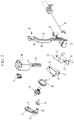
FIG. 2 is an exploded perspective view illustrating the power child lock device according to the exemplary embodiment of the present invention. -
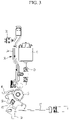
FIG. 3 is a front view illustrating a state in which the power child lock device according to the exemplary embodiment of the present invention is released. -
FIG. 4 is a view for explaining an operation of an inside handle in a state in which the power child lock device according to the exemplary embodiment of the present invention is released. -
FIG. 5 is a front view illustrating a state in which the power child lock device according to the exemplary embodiment of the present invention is locked. -
FIG. 6 is a view for explaining an operation of the inside handle in a state in which the power child lock device according to the exemplary embodiment of the present invention is locked. -
- 10: Drive motor
- 20: Worm
- 30: Switch link
- 31: Worm wheel gear
- 32: Link body
- 33: Pressing flange
- 40: Release lever
- 41: Pin hole
- 42: Coupling groove
- 50: Inside handle lever
- 51: Pin hole
- 52: Cable
- 53: Connecting hole
- 54: Coupling groove
- 60: Power child lever
- 61: Long hole
- 62: Coupling protrusion
- 63: Rim
- 70: Power child lock switch
- 81, 82: Return spring
- Hereinafter, exemplary embodiments of the present invention will be described in detail with reference to the accompanying drawings.
- Referring to
FIGS. 1 and2 , a vehicle door comprising a power child lock device according to an exemplary embodiment of the present invention includes adrive motor 10 serving as a rotation driving mechanism capable of rotating clockwise and counterclockwise, aworm 20 provided on a motor shaft of thedrive motor 10, aswitch link 30 moved vertically by an operation of thedrive motor 10 and having a cylindricalworm wheel gear 31 meshing with theworm 20, arelease lever 40 connected to a door latch by means of a cable and the like to release the door latch and installed to be rotatable by means of apin 45, aninside handle lever 50 installed to be rotatable by means of thepin 45 and connected, by means of acable 52, to an inside handle installed in a door of a vehicle, and apower child lever 60 configured to connect or separate therelease lever 40 and theinside handle lever 50. - The
drive motor 10 may be embedded in a casing 1. - The
switch link 30 has alink body 32 extending vertically based on the drawings. The cylindricalworm wheel gear 31, which protrudes approximately vertically from thelink body 32, may be provided at one side of thelink body 32. Apressing flange 33, which protrudes in a direction opposite to the cylindricalworm wheel gear 31, is provided at a lower end of thelink body 32. - In addition, the power child lock device may further include a power
child lock switch 70 turned on or off by theswitch link 30 as theswitch link 30 moves vertically and configured to transmit on/off signals to a door latch controller. - A
switch contact flange 34 may extend vertically from an upper portion of thelink body 32, and theswitch contact flange 34 comes into contact with the powerchild lock switch 70 to turn on the powerchild lock switch 70. Theswitch link 30 may have a switch-offinclined surface 35 inclined vertically to turn off the powerchild lock switch 70 by being spaced apart from the powerchild lock switch 70 when theswitch link 30 moves downward. - When the
drive motor 10 rotates in one direction, theworm 20 rotates integrally with themotor 10, the cylindricalworm wheel gear 31 and theswitch link 30 are moved downward by the rotation of theworm 20. When thedrive motor 10 rotates in the other direction, theworm wheel gear 31 and theswitch link 30 are moved upward. - An elliptical
long hole 61 into which thepin 45 is inserted may be formed in an upper portion of thepower child lever 60 so that thepower child lever 60 may be rotated by means of thepin 45. Acoupling protrusion 62 may be provided at a lower portion of thepower child lever 60. Arim 63 of thelong hole 61 is pressed by the pressingflange 33, such that thepower child lever 60 may be moved downward by means of thelong hole 61 with thepin 45 inserted into thepower child lever 60. - An upper portion of the
release lever 40 may be provided with apin hole 41 into which thepin 45 is inserted so that therelease lever 40 may be rotated by means of thepin 45. A lower portion of therelease lever 40 may be provided with a coupling groove 42 into which thecoupling protrusion 62 is inserted so that therelease lever 40 is connected to thepower child lever 60. - An upper portion of the
inside handle lever 50 may be provided with apin hole 51 into which thepin 45 is inserted so that theinside handle lever 50 may be rotated by means of thepin 45. A lower portion of theinside handle lever 50 may be provided with a connectinghole 53 into which thecable 52 is inserted and connected so that theinside handle lever 50 is connected, by means of thecable 52, to the inside handle installed in the door of the vehicle. Acoupling groove 54 may be provided between thepin hole 51 and the connectinghole 53, such that thecoupling protrusion 62 is inserted into thecoupling groove 54 so that theinside handle lever 50 is connected to therelease lever 40 by means of thepower child lever 60. - In addition, the power child lock device may further include return springs 81 and 82 configured to return the
power child lever 60 and therelease lever 40 to the original positions. -
FIG. 3 illustrates a state in which the power child lock device according to the exemplary embodiment of the present invention is released. In the state in which theswitch link 30 is moved upward, the powerchild lock switch 70 is turned on by coming into contact with theswitch contact flange 34 of theswitch link 30, and thecoupling protrusion 62 of thepower child lever 60 is inserted into the coupling groove 42 of therelease lever 40 and thecoupling groove 54 of theinside handle lever 50, such that therelease lever 40 and theinside handle lever 50 are integrally connected with each other through thepower child lever 60. - In this state, when an occupant pulls the inside handle installed in the rear door of the vehicle to open the rear door of the vehicle, an operating force of the inside handle is transmitted to the
inside handle lever 50 through thecable 52. As a result, as illustrated inFIG. 4 , theinside handle lever 50 is rotated counterclockwise, and therelease lever 40 is also simultaneously rotated counterclockwise by theinside handle lever 50, such that the door latch connected to the release lever by a cable or a rod is released, and thus the rear door may be opened. - Meanwhile, as illustrated in
FIG. 5 , when the driver operates a switch or the like to operate the power child lock, power is applied to thedrive motor 10, thedrive motor 10 rotates in one direction, theworm 20 is rotated by the rotation of thedrive motor 10, the cylindricalworm wheel gear 31 is moved downward, and theswitch link 30 is also moved downward. - Therefore, the switch-off
inclined surface 35 of theswitch link 30 is positioned to face the powerchild lock switch 70, such that the powerchild lock switch 70 is turned off by becoming spaced apart from theswitch link 30. - Further, the pressing
flange 33 of theswitch link 30 presses downward therim 63 of thepower child lever 60 by the downward movement of theswitch link 30. Therefore, with thepin 45 inserted into thepower child lever 60, thepower child lever 60 is moved downward, and thecoupling protrusion 62 is withdrawn from thecoupling groove 54 of theinside handle lever 50, such that theinside handle lever 50 and therelease lever 40 are separated without being connected with each other through thepower child lever 60. - In this state, as illustrated in
FIG. 6 , when the occupant pulls the inside handle installed in the rear door of the vehicle to open the rear door of the vehicle, the operating force of the inside handle is transmitted to theinside handle lever 50 through thecable 52, such that theinside handle lever 50 is rotated counterclockwise. However, because theinside handle lever 50 and therelease lever 40 are not connected to each other, therelease lever 40 is not rotated, and the release operating force is not transmitted to the door latch through therelease lever 40, such that the rear door remains locked, and the rear door cannot be opened. - Meanwhile, when the driver releases the power child lock by operating the switch or the like, the
drive motor 10 rotates in the other direction, and theswitch link 30 returns to the state illustrated inFIG. 3 while moving upward again. - According to the power child lock device according to the exemplary embodiment of the present invention, it is possible to reduce the number of components, costs and weights by simplifying the mechanism for operating the power child lock. In addition, it is possible to improve operational reliability by simplifying the power child lock structure.
- While this invention has been described in connection with what is presently considered to be practical exemplary embodiments, it is to be understood that the invention is not limited to the disclosed embodiments. On the contrary, it is intended to cover various modifications and equivalent arrangements included within the scope of the appended claims.
Claims (7)
- A vehicle door comprising:an inside handle; anda power child lock device comprising:a rotation driving mechanism;a switch link (30) connected to the rotation driving mechanism so as to be movable vertically by a rotational force of the rotation driving mechanism;an inside handle lever (50) cooperatively connected to the inside handle installed in the vehicle door;a release lever (40) connected to a door catch and configured to lock or release the door catch; anda power child lever (60) configured to selectively connect or separate the inside handle lever (50) and the release lever (40) by being moved by the switch link (30),wherein the rotation driving mechanism is a drive motor (10) capable of rotating clockwise and counterclockwise, wherein:the drive motor (10) has a worm (20) integrally rotated therewith;the switch link (30) has a cylindrical worm wheel gear (31) meshing with the worm (20);the switch link (30) has a link body (32) extending vertically;one side of the link body (32) is provided with the cylindrical worm wheel gear (31) that protrudes from the link body (32); anda lower end of the link body (32) is provided with a pressing flange (33) configured to press the power child lever (60) and protruding in a direction opposite to the cylindrical worm wheel gear (31).
- The vehicle door of claim 1, the power child lock device further comprising a power child lock switch (70) configured to be turned on or off by the switch link (30) in accordance with the movement of the switch link (30).
- The vehicle door of claim 2, wherein:the link body (32) has a switch contact flange (34) configured to turn on the power child lock switch (70) by coming into contact with the power child lock switch (70); andthe link body (32) has a switch-off inclined surface (35) configured to turn off the power child lock switch (70) by being spaced apart from the power child lock switch (70) when the switch link (30) moves downward.
- The vehicle door of one of claims 1-3, wherein:an upper portion of the power child lever (60) is provided with an elliptical long hole (61) into which a pin (45) is inserted so that the power child lever (60) is rotatable by means of the pin (45),a lower portion of the power child lever (60) is provided with a coupling protrusion (62), anda rim (63) of the long hole (61) is pressed by the pressing flange (33), such that the power child lever (60) is moved through the long hole (61) with the pin (45) inserted into the power child lever (60).
- The vehicle door of claim 4, wherein:an upper portion of the release lever (40) is provided with a pin hole (41) into which the pin (45) is inserted so that the release lever (40) is rotated by means of the pin (45); anda lower portion of the release lever (40) is provided with a coupling groove (42) into which the coupling protrusion (62) is inserted so that the release lever (40) is connected to the power child lever (60).
- The vehicle door of claim 4 or 5, wherein:an upper portion of the inside handle lever (50) is provided with a pin hole (51) into which the pin (45) is inserted so that the inside handle lever (50) is rotatable by means of the pin (45),a lower portion of the inside handle lever (50) is provided with a connecting hole (53) into which a cable (52) is inserted and connected so that the inside handle lever (50) is connected, through the cable (52), to the inside handle installed in the door of the vehicle, anda coupling groove (54), into which the coupling protrusion (62) is inserted so that the inside handle lever (50) is connected to the release lever (40) through the power child lever (60), is provided between the pin hole (51) and the connecting hole (53).
- The vehicle door of one of claims 1-6, the power child lock device further comprising a return spring (81, 82) configured to return the power child lever (60) and the release lever (40) to original positions.
Applications Claiming Priority (1)
| Application Number | Priority Date | Filing Date | Title |
|---|---|---|---|
| KR1020190100815A KR102633869B1 (en) | 2019-08-19 | 2019-08-19 | Power child lock device |
Publications (2)
| Publication Number | Publication Date |
|---|---|
| EP3783173A1 EP3783173A1 (en) | 2021-02-24 |
| EP3783173B1 true EP3783173B1 (en) | 2022-05-04 |
Family
ID=68581201
Family Applications (1)
| Application Number | Title | Priority Date | Filing Date |
|---|---|---|---|
| EP19208492.9A Active EP3783173B1 (en) | 2019-08-19 | 2019-11-12 | A vehicle door comprising a power child lock device |
Country Status (4)
| Country | Link |
|---|---|
| US (1) | US11499348B2 (en) |
| EP (1) | EP3783173B1 (en) |
| KR (1) | KR102633869B1 (en) |
| CN (1) | CN112392341B (en) |
Families Citing this family (5)
| Publication number | Priority date | Publication date | Assignee | Title |
|---|---|---|---|---|
| DE102022121658A1 (en) * | 2022-08-26 | 2024-02-29 | Kiekert Aktiengesellschaft | Motor vehicle lock |
| CN116104372B (en) * | 2022-11-10 | 2025-11-18 | 芜湖瑞智安汽车科技有限公司 | Child insurance for car door locks |
| US12607047B2 (en) * | 2023-01-26 | 2026-04-21 | Kiekert Ag | Motor vehicle latch |
| CN116122676B (en) * | 2023-02-13 | 2025-01-28 | 浙江天岳汽车电器有限公司 | A car door child lock |
| CN116397969B (en) * | 2023-04-21 | 2024-06-11 | 重庆长安汽车股份有限公司 | Control method and device for vehicle door child lock |
Family Cites Families (35)
| Publication number | Priority date | Publication date | Assignee | Title |
|---|---|---|---|---|
| US2785916A (en) * | 1954-07-30 | 1957-03-19 | Adolph J Mutti | Anti-crash auto door lock |
| US2916319A (en) * | 1957-07-26 | 1959-12-08 | Gen Motors Corp | Deck lid locking mechanism |
| US3933382A (en) * | 1973-07-13 | 1976-01-20 | Transport Security Systems, Inc. | Security lock |
| IT1091053B (en) * | 1975-12-01 | 1985-06-26 | Kiekert Soehne Arn | CENTRAL LOCKING DEVICE FOR VEHICLE DOORS |
| US4659121A (en) * | 1984-03-08 | 1987-04-21 | Mcgee Michael H | Garage door lock system |
| US4799719A (en) * | 1987-06-18 | 1989-01-24 | George Wood | Motor operated lock |
| DE8809256U1 (en) * | 1988-07-20 | 1988-09-22 | Kiekert GmbH & Co KG, 5628 Heiligenhaus | Motor vehicle door lock with lock housed in the motor vehicle door and child safety lock |
| DE3902776A1 (en) | 1988-08-13 | 1990-02-15 | Kiekert Gmbh Co Kg | MOTOR VEHICLE DOOR LOCK WITH CENTRAL LOCKING DRIVE AND ANTI-THEFT SECURITY |
| US4917419A (en) * | 1988-08-22 | 1990-04-17 | Mora Jr Saturnino F | Electromechanical door lock system |
| JP2576017Y2 (en) * | 1989-03-24 | 1998-07-09 | アイシン精機株式会社 | Child protector mechanism of door lock device |
| US5079964A (en) * | 1989-05-25 | 1992-01-14 | Mitsui Kinzoku Kogyo Kabushiki Kaisha | Actuator for door locking apparatus for vehicle |
| US5092638B1 (en) * | 1989-06-20 | 1995-04-04 | Mitsui Mining & Smelting Co | Child-lock mechanism for locking apparatus for vehicle |
| JP2585354Y2 (en) * | 1989-08-07 | 1998-11-18 | アイシン精機株式会社 | Child protector mechanism of door lock device |
| JP2533004B2 (en) * | 1991-02-16 | 1996-09-11 | 三井金属鉱業株式会社 | Electric lock device for trunk doors |
| US5537848A (en) * | 1994-06-27 | 1996-07-23 | General Motors Corporation | Deadbolt locking system |
| KR0171782B1 (en) * | 1995-12-14 | 1999-03-30 | 김태구 | Door lock structure for child protection of car |
| US5715713A (en) * | 1996-01-11 | 1998-02-10 | General Motors Corporation | Door latch locking actuator assembly |
| US5746459A (en) * | 1996-07-31 | 1998-05-05 | Independent Mobility Systems, Inc. | Power door latch method and apparatus |
| GB2330864A (en) | 1997-07-15 | 1999-05-05 | Rockwell Lvs | Vehicle door securing mechanism incorporating a child safety device |
| US6079757A (en) * | 1998-08-11 | 2000-06-27 | General Motors Corporation | Door latch with manually resettable deadbolt lock |
| US6199923B1 (en) * | 1999-06-10 | 2001-03-13 | Delphi Technologies, Inc. | Vehicle door latch |
| GB2360544B (en) * | 2000-03-23 | 2003-07-09 | Meritor Light Vehicle Sys Ltd | Power actuator arrangement |
| DE102009041101A1 (en) * | 2009-09-14 | 2011-03-24 | K.A. Schmersal Holding Gmbh & Co. Kg | Guard for a component for closing an opening |
| US8757680B2 (en) * | 2010-03-04 | 2014-06-24 | Leehan Door Corporation | Door lock assembly |
| KR101216625B1 (en) * | 2010-10-27 | 2012-12-31 | 평화정공 주식회사 | Rear door latch for vehicle |
| DE202012012039U1 (en) * | 2012-12-15 | 2014-03-19 | Kiekert Aktiengesellschaft | Motor vehicle door lock |
| JP6450991B2 (en) * | 2014-10-29 | 2019-01-16 | 三井金属アクト株式会社 | Vehicle door latch device |
| EP3392434A4 (en) | 2015-12-16 | 2019-08-07 | Mitsui Kinzoku ACT Corporation | AUTOMOTIVE DOOR LOCK DEVICE |
| US10619385B2 (en) | 2016-06-02 | 2020-04-14 | Magna Closures Inc. | Closure latch for a rear vehicle door having an emergency child lock release mechanism |
| KR101972508B1 (en) * | 2016-08-19 | 2019-04-26 | 주식회사 우보테크 | Latch system for door of vehicle |
| CN106401324B (en) * | 2016-12-02 | 2018-08-14 | 上海恩坦华汽车门系统有限公司 | A kind of electronic insurance for children structure of automobile door lock |
| US11280118B2 (en) * | 2016-12-19 | 2022-03-22 | Kiekert Ag | Vehicle door lock with gear thrust retainer |
| US10808424B2 (en) * | 2017-05-01 | 2020-10-20 | Amesbury Group, Inc. | Modular multi-point lock |
| KR101935921B1 (en) * | 2017-11-06 | 2019-01-07 | 대동도어 주식회사 | Door latch for vehicle |
| KR102518596B1 (en) | 2018-01-30 | 2023-04-05 | 현대자동차 주식회사 | Power child lock operating device |
-
2019
- 2019-08-19 KR KR1020190100815A patent/KR102633869B1/en active Active
- 2019-10-25 US US16/663,595 patent/US11499348B2/en active Active
- 2019-11-12 EP EP19208492.9A patent/EP3783173B1/en active Active
- 2019-11-28 CN CN201911192383.6A patent/CN112392341B/en active Active
Also Published As
| Publication number | Publication date |
|---|---|
| KR102633869B1 (en) | 2024-02-05 |
| CN112392341B (en) | 2022-11-22 |
| KR20210021658A (en) | 2021-03-02 |
| CN112392341A (en) | 2021-02-23 |
| US11499348B2 (en) | 2022-11-15 |
| US20210054666A1 (en) | 2021-02-25 |
| EP3783173A1 (en) | 2021-02-24 |
Similar Documents
| Publication | Publication Date | Title |
|---|---|---|
| US11499348B2 (en) | Power child lock device | |
| CN108204184B (en) | Back door opening and closing device for vehicle | |
| CN108979366B (en) | Trunk lid latch assembly for vehicle | |
| KR20200127320A (en) | Motor??driven door latch for vehicle | |
| CN1454280A (en) | Electrically operated detent latch | |
| KR101918367B1 (en) | Trunk latch module for vehicle | |
| CN112302437B (en) | Electric door lock for vehicle | |
| US11365567B2 (en) | Power child lock system for vehicle | |
| EP3517716B1 (en) | Power child lock operating device | |
| JP3921043B2 (en) | Vehicle door lock device | |
| EP1580365A1 (en) | Latch mechanism | |
| CN1987028A (en) | Automobile door lock | |
| US12188268B2 (en) | Vehicle door latch | |
| US20240151078A1 (en) | Vehicle door latch | |
| KR102219164B1 (en) | Tail gate and trunk latch | |
| KR100303367B1 (en) | Door ratch assembly for automobile | |
| CN117545905A (en) | Closure assembly for a vehicle cover | |
| US12320167B2 (en) | Motor vehicle lock | |
| JP4673797B2 (en) | Vehicle door lock device | |
| US20020050720A1 (en) | Coupling device for door locking systems | |
| JPH01247677A (en) | Locking device for vehicle door | |
| EP3575523A1 (en) | Door lock device | |
| KR102799301B1 (en) | Door rock apparatus for vehicle | |
| CN218029543U (en) | Button type external lock | |
| KR100431985B1 (en) | Door locker of a driver's seat for vehicles |
Legal Events
| Date | Code | Title | Description |
|---|---|---|---|
| PUAI | Public reference made under article 153(3) epc to a published international application that has entered the european phase |
Free format text: ORIGINAL CODE: 0009012 |
|
| STAA | Information on the status of an ep patent application or granted ep patent |
Free format text: STATUS: THE APPLICATION HAS BEEN PUBLISHED |
|
| STAA | Information on the status of an ep patent application or granted ep patent |
Free format text: STATUS: REQUEST FOR EXAMINATION WAS MADE |
|
| AK | Designated contracting states |
Kind code of ref document: A1 Designated state(s): AL AT BE BG CH CY CZ DE DK EE ES FI FR GB GR HR HU IE IS IT LI LT LU LV MC MK MT NL NO PL PT RO RS SE SI SK SM TR |
|
| AX | Request for extension of the european patent |
Extension state: BA ME |
|
| 17P | Request for examination filed |
Effective date: 20210209 |
|
| RBV | Designated contracting states (corrected) |
Designated state(s): AL AT BE BG CH CY CZ DE DK EE ES FI FR GB GR HR HU IE IS IT LI LT LU LV MC MK MT NL NO PL PT RO RS SE SI SK SM TR |
|
| RAP3 | Party data changed (applicant data changed or rights of an application transferred) |
Owner name: HYUNDAI MOTOR COMPANY Owner name: KIA CORPORATION |
|
| GRAP | Despatch of communication of intention to grant a patent |
Free format text: ORIGINAL CODE: EPIDOSNIGR1 |
|
| STAA | Information on the status of an ep patent application or granted ep patent |
Free format text: STATUS: GRANT OF PATENT IS INTENDED |
|
| RIC1 | Information provided on ipc code assigned before grant |
Ipc: E05B 81/72 20140101ALI20211103BHEP Ipc: E05B 81/64 20140101ALI20211103BHEP Ipc: E05B 81/16 20140101ALI20211103BHEP Ipc: E05B 81/40 20140101ALI20211103BHEP Ipc: E05B 81/06 20140101ALI20211103BHEP Ipc: E05B 77/26 20140101AFI20211103BHEP |
|
| INTG | Intention to grant announced |
Effective date: 20211208 |
|
| GRAS | Grant fee paid |
Free format text: ORIGINAL CODE: EPIDOSNIGR3 |
|
| GRAA | (expected) grant |
Free format text: ORIGINAL CODE: 0009210 |
|
| STAA | Information on the status of an ep patent application or granted ep patent |
Free format text: STATUS: THE PATENT HAS BEEN GRANTED |
|
| AK | Designated contracting states |
Kind code of ref document: B1 Designated state(s): AL AT BE BG CH CY CZ DE DK EE ES FI FR GB GR HR HU IE IS IT LI LT LU LV MC MK MT NL NO PL PT RO RS SE SI SK SM TR |
|
| REG | Reference to a national code |
Ref country code: GB Ref legal event code: FG4D |
|
| RIN1 | Information on inventor provided before grant (corrected) |
Inventor name: SEO, YONGDAE |
|
| REG | Reference to a national code |
Ref country code: CH Ref legal event code: EP |
|
| REG | Reference to a national code |
Ref country code: AT Ref legal event code: REF Ref document number: 1489200 Country of ref document: AT Kind code of ref document: T Effective date: 20220515 |
|
| REG | Reference to a national code |
Ref country code: IE Ref legal event code: FG4D Ref country code: DE Ref legal event code: R096 Ref document number: 602019014418 Country of ref document: DE |
|
| REG | Reference to a national code |
Ref country code: LT Ref legal event code: MG9D |
|
| REG | Reference to a national code |
Ref country code: NL Ref legal event code: MP Effective date: 20220504 |
|
| REG | Reference to a national code |
Ref country code: AT Ref legal event code: MK05 Ref document number: 1489200 Country of ref document: AT Kind code of ref document: T Effective date: 20220504 |
|
| PG25 | Lapsed in a contracting state [announced via postgrant information from national office to epo] |
Ref country code: SE Free format text: LAPSE BECAUSE OF FAILURE TO SUBMIT A TRANSLATION OF THE DESCRIPTION OR TO PAY THE FEE WITHIN THE PRESCRIBED TIME-LIMIT Effective date: 20220504 Ref country code: PT Free format text: LAPSE BECAUSE OF FAILURE TO SUBMIT A TRANSLATION OF THE DESCRIPTION OR TO PAY THE FEE WITHIN THE PRESCRIBED TIME-LIMIT Effective date: 20220905 Ref country code: NO Free format text: LAPSE BECAUSE OF FAILURE TO SUBMIT A TRANSLATION OF THE DESCRIPTION OR TO PAY THE FEE WITHIN THE PRESCRIBED TIME-LIMIT Effective date: 20220804 Ref country code: NL Free format text: LAPSE BECAUSE OF FAILURE TO SUBMIT A TRANSLATION OF THE DESCRIPTION OR TO PAY THE FEE WITHIN THE PRESCRIBED TIME-LIMIT Effective date: 20220504 Ref country code: LT Free format text: LAPSE BECAUSE OF FAILURE TO SUBMIT A TRANSLATION OF THE DESCRIPTION OR TO PAY THE FEE WITHIN THE PRESCRIBED TIME-LIMIT Effective date: 20220504 Ref country code: HR Free format text: LAPSE BECAUSE OF FAILURE TO SUBMIT A TRANSLATION OF THE DESCRIPTION OR TO PAY THE FEE WITHIN THE PRESCRIBED TIME-LIMIT Effective date: 20220504 Ref country code: GR Free format text: LAPSE BECAUSE OF FAILURE TO SUBMIT A TRANSLATION OF THE DESCRIPTION OR TO PAY THE FEE WITHIN THE PRESCRIBED TIME-LIMIT Effective date: 20220805 Ref country code: FI Free format text: LAPSE BECAUSE OF FAILURE TO SUBMIT A TRANSLATION OF THE DESCRIPTION OR TO PAY THE FEE WITHIN THE PRESCRIBED TIME-LIMIT Effective date: 20220504 Ref country code: BG Free format text: LAPSE BECAUSE OF FAILURE TO SUBMIT A TRANSLATION OF THE DESCRIPTION OR TO PAY THE FEE WITHIN THE PRESCRIBED TIME-LIMIT Effective date: 20220804 Ref country code: AT Free format text: LAPSE BECAUSE OF FAILURE TO SUBMIT A TRANSLATION OF THE DESCRIPTION OR TO PAY THE FEE WITHIN THE PRESCRIBED TIME-LIMIT Effective date: 20220504 |
|
| PG25 | Lapsed in a contracting state [announced via postgrant information from national office to epo] |
Ref country code: RS Free format text: LAPSE BECAUSE OF FAILURE TO SUBMIT A TRANSLATION OF THE DESCRIPTION OR TO PAY THE FEE WITHIN THE PRESCRIBED TIME-LIMIT Effective date: 20220504 Ref country code: PL Free format text: LAPSE BECAUSE OF FAILURE TO SUBMIT A TRANSLATION OF THE DESCRIPTION OR TO PAY THE FEE WITHIN THE PRESCRIBED TIME-LIMIT Effective date: 20220504 Ref country code: LV Free format text: LAPSE BECAUSE OF FAILURE TO SUBMIT A TRANSLATION OF THE DESCRIPTION OR TO PAY THE FEE WITHIN THE PRESCRIBED TIME-LIMIT Effective date: 20220504 Ref country code: IS Free format text: LAPSE BECAUSE OF FAILURE TO SUBMIT A TRANSLATION OF THE DESCRIPTION OR TO PAY THE FEE WITHIN THE PRESCRIBED TIME-LIMIT Effective date: 20220904 |
|
| PG25 | Lapsed in a contracting state [announced via postgrant information from national office to epo] |
Ref country code: SM Free format text: LAPSE BECAUSE OF FAILURE TO SUBMIT A TRANSLATION OF THE DESCRIPTION OR TO PAY THE FEE WITHIN THE PRESCRIBED TIME-LIMIT Effective date: 20220504 Ref country code: SK Free format text: LAPSE BECAUSE OF FAILURE TO SUBMIT A TRANSLATION OF THE DESCRIPTION OR TO PAY THE FEE WITHIN THE PRESCRIBED TIME-LIMIT Effective date: 20220504 Ref country code: RO Free format text: LAPSE BECAUSE OF FAILURE TO SUBMIT A TRANSLATION OF THE DESCRIPTION OR TO PAY THE FEE WITHIN THE PRESCRIBED TIME-LIMIT Effective date: 20220504 Ref country code: ES Free format text: LAPSE BECAUSE OF FAILURE TO SUBMIT A TRANSLATION OF THE DESCRIPTION OR TO PAY THE FEE WITHIN THE PRESCRIBED TIME-LIMIT Effective date: 20220504 Ref country code: EE Free format text: LAPSE BECAUSE OF FAILURE TO SUBMIT A TRANSLATION OF THE DESCRIPTION OR TO PAY THE FEE WITHIN THE PRESCRIBED TIME-LIMIT Effective date: 20220504 Ref country code: DK Free format text: LAPSE BECAUSE OF FAILURE TO SUBMIT A TRANSLATION OF THE DESCRIPTION OR TO PAY THE FEE WITHIN THE PRESCRIBED TIME-LIMIT Effective date: 20220504 Ref country code: CZ Free format text: LAPSE BECAUSE OF FAILURE TO SUBMIT A TRANSLATION OF THE DESCRIPTION OR TO PAY THE FEE WITHIN THE PRESCRIBED TIME-LIMIT Effective date: 20220504 |
|
| REG | Reference to a national code |
Ref country code: DE Ref legal event code: R097 Ref document number: 602019014418 Country of ref document: DE |
|
| PLBE | No opposition filed within time limit |
Free format text: ORIGINAL CODE: 0009261 |
|
| STAA | Information on the status of an ep patent application or granted ep patent |
Free format text: STATUS: NO OPPOSITION FILED WITHIN TIME LIMIT |
|
| PG25 | Lapsed in a contracting state [announced via postgrant information from national office to epo] |
Ref country code: AL Free format text: LAPSE BECAUSE OF FAILURE TO SUBMIT A TRANSLATION OF THE DESCRIPTION OR TO PAY THE FEE WITHIN THE PRESCRIBED TIME-LIMIT Effective date: 20220504 |
|
| 26N | No opposition filed |
Effective date: 20230207 |
|
| PG25 | Lapsed in a contracting state [announced via postgrant information from national office to epo] |
Ref country code: SI Free format text: LAPSE BECAUSE OF FAILURE TO SUBMIT A TRANSLATION OF THE DESCRIPTION OR TO PAY THE FEE WITHIN THE PRESCRIBED TIME-LIMIT Effective date: 20220504 |
|
| PG25 | Lapsed in a contracting state [announced via postgrant information from national office to epo] |
Ref country code: MC Free format text: LAPSE BECAUSE OF FAILURE TO SUBMIT A TRANSLATION OF THE DESCRIPTION OR TO PAY THE FEE WITHIN THE PRESCRIBED TIME-LIMIT Effective date: 20220504 |
|
| REG | Reference to a national code |
Ref country code: CH Ref legal event code: PL |
|
| P01 | Opt-out of the competence of the unified patent court (upc) registered |
Effective date: 20230530 |
|
| REG | Reference to a national code |
Ref country code: BE Ref legal event code: MM Effective date: 20221130 |
|
| PG25 | Lapsed in a contracting state [announced via postgrant information from national office to epo] |
Ref country code: LI Free format text: LAPSE BECAUSE OF NON-PAYMENT OF DUE FEES Effective date: 20221130 Ref country code: CH Free format text: LAPSE BECAUSE OF NON-PAYMENT OF DUE FEES Effective date: 20221130 |
|
| PG25 | Lapsed in a contracting state [announced via postgrant information from national office to epo] |
Ref country code: LU Free format text: LAPSE BECAUSE OF NON-PAYMENT OF DUE FEES Effective date: 20221112 |
|
| PG25 | Lapsed in a contracting state [announced via postgrant information from national office to epo] |
Ref country code: IE Free format text: LAPSE BECAUSE OF NON-PAYMENT OF DUE FEES Effective date: 20221112 |
|
| PG25 | Lapsed in a contracting state [announced via postgrant information from national office to epo] |
Ref country code: BE Free format text: LAPSE BECAUSE OF NON-PAYMENT OF DUE FEES Effective date: 20221130 |
|
| PG25 | Lapsed in a contracting state [announced via postgrant information from national office to epo] |
Ref country code: CY Free format text: LAPSE BECAUSE OF FAILURE TO SUBMIT A TRANSLATION OF THE DESCRIPTION OR TO PAY THE FEE WITHIN THE PRESCRIBED TIME-LIMIT Effective date: 20220504 |
|
| PG25 | Lapsed in a contracting state [announced via postgrant information from national office to epo] |
Ref country code: MK Free format text: LAPSE BECAUSE OF FAILURE TO SUBMIT A TRANSLATION OF THE DESCRIPTION OR TO PAY THE FEE WITHIN THE PRESCRIBED TIME-LIMIT Effective date: 20220504 Ref country code: HU Free format text: LAPSE BECAUSE OF FAILURE TO SUBMIT A TRANSLATION OF THE DESCRIPTION OR TO PAY THE FEE WITHIN THE PRESCRIBED TIME-LIMIT; INVALID AB INITIO Effective date: 20191112 |
|
| PG25 | Lapsed in a contracting state [announced via postgrant information from national office to epo] |
Ref country code: MT Free format text: LAPSE BECAUSE OF FAILURE TO SUBMIT A TRANSLATION OF THE DESCRIPTION OR TO PAY THE FEE WITHIN THE PRESCRIBED TIME-LIMIT Effective date: 20220504 |
|
| PG25 | Lapsed in a contracting state [announced via postgrant information from national office to epo] |
Ref country code: BG Free format text: LAPSE BECAUSE OF FAILURE TO SUBMIT A TRANSLATION OF THE DESCRIPTION OR TO PAY THE FEE WITHIN THE PRESCRIBED TIME-LIMIT Effective date: 20220504 |
|
| PG25 | Lapsed in a contracting state [announced via postgrant information from national office to epo] |
Ref country code: BG Free format text: LAPSE BECAUSE OF FAILURE TO SUBMIT A TRANSLATION OF THE DESCRIPTION OR TO PAY THE FEE WITHIN THE PRESCRIBED TIME-LIMIT Effective date: 20220504 |
|
| PG25 | Lapsed in a contracting state [announced via postgrant information from national office to epo] |
Ref country code: TR Free format text: LAPSE BECAUSE OF FAILURE TO SUBMIT A TRANSLATION OF THE DESCRIPTION OR TO PAY THE FEE WITHIN THE PRESCRIBED TIME-LIMIT Effective date: 20220504 |
|
| PGFP | Annual fee paid to national office [announced via postgrant information from national office to epo] |
Ref country code: DE Payment date: 20251020 Year of fee payment: 7 |
|
| PGFP | Annual fee paid to national office [announced via postgrant information from national office to epo] |
Ref country code: GB Payment date: 20251023 Year of fee payment: 7 |
|
| PGFP | Annual fee paid to national office [announced via postgrant information from national office to epo] |
Ref country code: IT Payment date: 20251021 Year of fee payment: 7 |
|
| PGFP | Annual fee paid to national office [announced via postgrant information from national office to epo] |
Ref country code: FR Payment date: 20251021 Year of fee payment: 7 |