EP3782885B1 - Straddled vehicle - Google Patents
Straddled vehicle Download PDFInfo
- Publication number
- EP3782885B1 EP3782885B1 EP20191644.2A EP20191644A EP3782885B1 EP 3782885 B1 EP3782885 B1 EP 3782885B1 EP 20191644 A EP20191644 A EP 20191644A EP 3782885 B1 EP3782885 B1 EP 3782885B1
- Authority
- EP
- European Patent Office
- Prior art keywords
- vehicle
- light
- emitting surface
- regards
- bulb
- Prior art date
- Legal status (The legal status is an assumption and is not a legal conclusion. Google has not performed a legal analysis and makes no representation as to the accuracy of the status listed.)
- Active
Links
Images



Classifications
-
- B—PERFORMING OPERATIONS; TRANSPORTING
- B62—LAND VEHICLES FOR TRAVELLING OTHERWISE THAN ON RAILS
- B62J—CYCLE SADDLES OR SEATS; AUXILIARY DEVICES OR ACCESSORIES SPECIALLY ADAPTED TO CYCLES AND NOT OTHERWISE PROVIDED FOR, e.g. ARTICLE CARRIERS OR CYCLE PROTECTORS
- B62J6/00—Arrangement of optical signalling or lighting devices on cycles; Mounting or supporting thereof; Circuits therefor
- B62J6/02—Headlights
- B62J6/022—Headlights specially adapted for motorcycles or the like
- B62J6/026—Headlights specially adapted for motorcycles or the like characterised by the structure, e.g. casings
-
- B—PERFORMING OPERATIONS; TRANSPORTING
- B60—VEHICLES IN GENERAL
- B60Q—ARRANGEMENT OF SIGNALLING OR LIGHTING DEVICES, THE MOUNTING OR SUPPORTING THEREOF OR CIRCUITS THEREFOR, FOR VEHICLES IN GENERAL
- B60Q1/00—Arrangement of optical signalling or lighting devices, the mounting or supporting thereof or circuits therefor
- B60Q1/0029—Spatial arrangement
- B60Q1/0035—Spatial arrangement relative to the vehicle
-
- B—PERFORMING OPERATIONS; TRANSPORTING
- B60—VEHICLES IN GENERAL
- B60Q—ARRANGEMENT OF SIGNALLING OR LIGHTING DEVICES, THE MOUNTING OR SUPPORTING THEREOF OR CIRCUITS THEREFOR, FOR VEHICLES IN GENERAL
- B60Q1/00—Arrangement of optical signalling or lighting devices, the mounting or supporting thereof or circuits therefor
- B60Q1/02—Arrangement of optical signalling or lighting devices, the mounting or supporting thereof or circuits therefor the devices being primarily intended to illuminate the way ahead or to illuminate other areas of way or environments
- B60Q1/04—Arrangement of optical signalling or lighting devices, the mounting or supporting thereof or circuits therefor the devices being primarily intended to illuminate the way ahead or to illuminate other areas of way or environments the devices being headlights
- B60Q1/0408—Arrangement of optical signalling or lighting devices, the mounting or supporting thereof or circuits therefor the devices being primarily intended to illuminate the way ahead or to illuminate other areas of way or environments the devices being headlights built into the vehicle body, e.g. details concerning the mounting of the headlamps on the vehicle body
-
- B—PERFORMING OPERATIONS; TRANSPORTING
- B62—LAND VEHICLES FOR TRAVELLING OTHERWISE THAN ON RAILS
- B62J—CYCLE SADDLES OR SEATS; AUXILIARY DEVICES OR ACCESSORIES SPECIALLY ADAPTED TO CYCLES AND NOT OTHERWISE PROVIDED FOR, e.g. ARTICLE CARRIERS OR CYCLE PROTECTORS
- B62J17/00—Weather guards for riders; Fairings or stream-lining parts not otherwise provided for
- B62J17/02—Weather guards for riders; Fairings or stream-lining parts not otherwise provided for shielding only the rider's front
-
- B—PERFORMING OPERATIONS; TRANSPORTING
- B62—LAND VEHICLES FOR TRAVELLING OTHERWISE THAN ON RAILS
- B62K—CYCLES; CYCLE FRAMES; CYCLE STEERING DEVICES; RIDER-OPERATED TERMINAL CONTROLS SPECIALLY ADAPTED FOR CYCLES; CYCLE AXLE SUSPENSIONS; CYCLE SIDECARS, FORECARS, OR THE LIKE
- B62K2202/00—Motorised scooters
Definitions
- the present invention relates to a straddled vehicle and in particular relates to a headlight unit of a straddled vehicle.
- JP H08 310465 A discloses a straddled vehicle according to the preamble of claim 1.
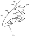
- Patent Document TW 1510385 discloses a scooter type vehicle that is one type of straddled vehicle. As illustrated in FIG. 1 , the scooter type vehicle includes a head pipe (not illustrated), a front portion cover 1000 arranged in front of the head pipe, and a headlight unit 2000 arranged in the front portion cover 1000.
- the front portion cover 1000 includes a front cover portion 1011 that is arranged above the headlight unit 2000.
- the headlight unit 2000 includes: a housing portion 2021, the front surface portion of which is open; a transparent cover portion 2022 that is provided on the front surface of the housing portion 2021 and that protrudes further to the front than the front cover portion 1011; and a bulb 2023 and a reflector portion 2024 which are accommodated inside a space formed by the housing portion 2021 and the transparent cover portion 2022.
- the front cover portion 1011 covers an upper end of the transparent cover portion 2022 at a position above the reflector portion 2024.
- the transparent cover portion 2022 is formed so as to protrude further to the front than the front cover portion 1011 and be exposed.
- the front cover portion 1011 disclosed in Patent Document TW 1510385 covers the upper end of the transparent cover portion 2022 at a position above the reflector portion 2024, and the transparent cover portion 2022 of the headlight unit 2000 is formed so as to protrude further to the front than the front cover portion 1011 and be exposed.
- the heat space is larger than necessary on days when only a small amount of thermal energy is acquired from the sunlight such as on cloudy or rainy days.
- the temperature inside the headlight unit 2000 tends not to rise and rainwater clinging to the outer surface of the transparent cover portion 2022 is not easily evaporated.
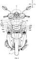
- FIG. 2 it has been considered arranging the font edge portion of a front cover portion 3000 further downward and forward than an upper edge portion of the reflector portion, and extending a transparent cover portion 4000 of the headlight unit rearward and downward of the vehicle from the front edge portion of the front cover portion 3000, thereby suppressing an increase in size in order to resolve the aforementioned problem.
- the amount of shielding by the front cover portion 3000 is increased.
- the amount of the transparent cover portion 4000 of the headlight unit rearward and downward of the vehicle is reduced, whereby the amount of sunlight entering the inside of the headlight unit can be reduced, the thermal energy acquired from sunlight is less, and the volume of the heat space can be reduced.
- rainwater is less likely to become attached to the transparent cover portion 4000 and less rainwater clings to the transparent cover portion 4000 in comparison to a conventional headlight unit. Furthermore, the amount of exposure of the transparent cover portion 4000 is reduced as seen in the vehicle plan view, and therefore fluctuation of the amount of thermal energy acquired from sunlight between sunny days and cloudy days is reduced and the heat space volume required for sunny days can be reduced. Consequently, an increase in the size of the headlight unit can be suppressed.
- the high beam light HL is necessarily irradiated further in the forward direction in comparison to the low beam light and a portion of the high beam light is reflected by the reflector below the bulb and irradiated in the forward direction of the vehicle.
- the light-emitting surface of the transparent cover portion 4000 becomes an inverse inclined surface and the incident angle of the high beam light HL tends to deviate from 0-degrees with respect to the transparent cover portion 4000 (that is, vertical incidence tends to be lost).
- the high beam light HL is refracted by the inverse inclined surface of the transparent cover portion 4000 and the amount of high beam light irradiated toward the intended location is reduced.
- the light-emitting surface of the transparent cover portion 4000 is an inverse inclined surface
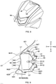
- the traveling wind flows along the inverse inclined surface whereby the rainwater W clinging to the transparent cover portion 4000 tends to pool at the bottom of the transparent cover portion 4000.
- the high beam light HL is more likely to be diffused when passing through the transparent cover portion 4000 due to the rainwater W pooled at the bottom of the transparent cover portion 4000, and therefore, there is a concern that the amount of light of the high beam irradiated toward the intended location is reduced.
- an object of the present invention is to provide a straddled vehicle provided with a headlight unit with which rainwater clinging to the transparent cover portion can be easily removed while suppressing an increase in the size of the headlight unit.
- a straddled vehicle that includes a head pipe, a front portion cover arranged in front of the head pipe, and a headlight unit arranged in the front portion cover.
- the front portion cover includes a front cover portion that is arranged above the headlight unit.
- the headlight unit includes a bulb for emitting light, a reflector portion for reflecting the light from the bulb, a housing portion that accommodates the bulb and the reflector portion, a transparent cover portion that covers the bulb and the reflector portion from the front, and a lamp chamber formed by the housing portion and the transparent cover portion.
- the front cover portion extends obliquely downward toward the front of the vehicle at least from above an upper end of the transparent cover portion, and a front edge portion of the front cover portion is arranged further downward and forward than an upper edge portion of the reflector portion.
- the transparent cover portion includes a light-emitting surface that is exposed to the outside and irradiates the light from the bulb in the forward direction of the vehicle, and the light-emitting surface includes, as seen in a cross-section at the center in the vehicle left-right direction, a light-emitting surface upper portion that extends rearward and downward of the vehicle from the front edge portion of the front cover portion, and a light-emitting surface lower portion that extends forward and downward of the vehicle from the light-emitting surface upper portion.
- a boundary of the light-emitting surface upper portion and the light-emitting surface lower portion is positioned below an upper end of the bulb and above a lower end of the bulb as seen in the cross-section at the center in the vehicle left-right direction.
- the reflector portion includes, at least, a reflector upper portion that is positioned above the bulb, extends rearward and downward of the vehicle, and reflects the light from the bulb in the forward direction of the vehicle, and a reflector lower portion that is positioned below the bulb, extends forward and downward of the vehicle, and reflects the light from the bulb in the forward direction of the vehicle.
- the front edge portion of the front cover portion of the straddled vehicle of the present teaching is arranged further downward and forward than the upper edge portion of the reflector portion, and the light-emitting surface upper portion extends rearward and downward of the vehicle from the front edge portion of the front cover portion, whereby it is difficult for sunlight to enter the lamp chamber from the transparent cover portion which is not shielded by the front cover portion.
- changes in temperature inside the lamp chamber (heat space) between sunny days and cloudy days are reduced and therefore the lamp chamber can be made smaller.
- the light-emitting surface upper portion is configured to extend rearward and downward of the vehicle from the front edge portion of the front cover portion to form an inverse inclined surface, whereby the portion exposed upward is reduced and it is difficult for rainwater falling from the sky to cling to the light-emitting surface.
- the light-emitting surface lower portion is configured to extend forward and downward of the vehicle from the light-emitting surface upper portion to form a forward inclined surface, and the reflector lower portion extends forward and downward of the vehicle, whereby the incident angle of the high beam light with respect to the light-emitting surface lower portion can be easily configured to approach 0-degrees (namely, vertical incidence).
- the amount of light refracted downward by the transparent cover portion can be reduced and the amount of high beam light irradiated toward the intended location can be assured.
- the light-emitting surface lower portion is configured to extend forward and downward of the vehicle from the light-emitting surface upper portion to form a forward inclined surface, whereby the situation of rainwater, which is splashed upward by the vehicle when traveling, clinging to the light-emitting surface can be prevented.
- the reflector upper portion in the straddled vehicle of the present teaching preferably includes an upper effective portion that is inclined in the same direction as the light-emitting surface upper portion as seen in the cross-section at the center in the vehicle left-right direction
- the reflector lower portion preferably includes a lower effective portion that is inclined in the same direction as the light-emitting surface lower portion as seen in the cross-section at the center in the vehicle left-right direction.
- the amount of low beam light and high beam light irradiated toward the intended location can be more effectively assured due to the upper effective portion and the lower effective portion in the straddled vehicle of the present teaching.
- the bulb of the straddled vehicle of the present teaching preferably includes an illumination portion and a socket portion to which the illumination portion is attached, and the boundary of the light-emitting surface upper portion and the light-emitting surface lower portion is preferably positioned between the upper end and the lower end of the illumination portion as seen in the cross-section at the center in the vehicle left-right direction.
- a front end of the light-emitting surface lower portion in the straddled vehicle of the present teaching is preferably positioned further to the front of the vehicle than a front end of the light-emitting surface upper portion as seen in the cross-section at the center in the vehicle left-right direction.
- the straddled vehicle of the present teaching is configured such that the light-emitting surface lower portion is a forward inclined surface that extends forward and downward of the vehicle from the light-emitting upper surface and the front end of the light-emitting surface lower portion is positioned further to the front of the vehicle than the front end of the light-emitting surface upper portion, whereby the rainwater splashed upward by the vehicle during traveling can be can be blocked and clinging of the rainwater splashed upward by the vehicle when traveling can be prevented more effectively.
- the traveling wind is easily guided along the surface and rainwater clinging to the light-emitting surface lower portion can be moved easily to the boundary of the light-emitting surface upper portion and the light-emitting surface lower portion by the traveling wind.
- Rainwater that has pooled on the boundary is easily evaporated by the heat from the center of the bulb.
- the front portion cover of the straddled vehicle of the present teaching preferably includes a lower cover portion that is arranged below the headlight unit and extends downward from the lower edge of the headlight unit.
- the lower cover portion of the straddled vehicle of the present teaching preferably extends forward and downward of the vehicle.
- the lower cover portion extends forward and downward of the vehicle whereby the traveling wind is guided easily and is able to flow toward the light-emitting surface lower portion.
- Rainwater clinging to the light-emitting surface lower portion can be moved easily to the boundary of the light-emitting surface upper portion and the light-emitting surface lower portion by the traveling wind. Rainwater that has pooled on the boundary is easily evaporated by the heat from the center of the bulb.
- the position corresponding to the bulb within the transparent cover portion is preferably positioned further to the rear of the vehicle than an imaginary line that connects the front end of the light-emitting surface upper portion and the front end of the light-emitting surface lower portion in the straddled vehicle of the present teaching.
- the lamp chamber (heat space) of the straddled vehicle of the present teaching is configured so that a change in the temperature between sunny days and cloudy days is reduced, the required volume of the heat space for sunny days is reduced, and a heat space that is sufficient even for sunny days can be assured.
- the position corresponding to the bulb within the transparent cover portion is near the center of the bulb and heat from the center of the bulb is easily transmitted to the position corresponding to the bulb in the transparent cover portion, whereby rainwater pooled at the position corresponding to the bulb in the transparent cover portion is easily evaporated by the heat from the center of the bulb.
- the boundary of the light-emitting surface upper portion and the light-emitting surface lower portion in the straddled vehicle of the present teaching preferably extends to the left and right sides and upward from the center in the vehicle left-right direction as seen in the vehicle front view, and preferably extends upward and rearward from the front of the vehicle as seen in the vehicle side view.
- the traveling wind flows along the shape of the boundary in the straddled vehicle of the present teaching, whereby rainwater is moved easily outward in the left and right sides of the transparent cover portion and rearward and therefore does not easily cling to the transparent cover portion.
- the directions forward, rearward, leftward, rightward, upward, and downward respectively have the same meaning as toward the front of the vehicle, toward the rear of the vehicle, toward the left in the vehicle left-right direction, toward the right in the vehicle left-right direction, upward in the vehicle up-down direction, and downward in the vehicle up-down direction as seen from a rider sitting on the straddled vehicle 1. That is, the above directions mean toward the front of the vehicle, toward the rear of the vehicle with regards to the vehicle front-rear direction, toward the left of the vehicle, toward the right of the vehicle with regards to the vehicle left-right direction, the vehicle upward direction, and the vehicle downward direction with regards to the vehicle up-down direction as seen from the rear of the vehicle.
- FIG. 4 is a left side view of the straddled vehicle 1 according to the present teaching.
- FIG. 5 is a localized enlarged front view illustrating a portion of a structure of a vehicle front portion of the straddled vehicle 1 according to the present teaching.
- FIG. 6 is a localized enlarged cross-sectional view illustrating a portion of a structure of the vehicle front portion of the straddled vehicle 1 according to the present teaching.
- FIG. 7 is a localized enlarged front view illustrating the front portion cover and a headlight unit of the straddled vehicle 1 according to the present teaching.
- FIG. 8 illustrates the front portion cover and the headlight unit as seen from in front and to the left of the vehicle.
- FIG. 9 is a localized enlarged cross-sectional view for explaining the arrangement relationship among the members of the headlight unit.
- the straddled vehicle 1 is a so-called "under-bone” type straddled vehicle.
- the straddled vehicle 1 includes a vehicle body frame 2, a steering mechanism 3, a vehicle body cover 4, a front wheel 5, a seat 6, a handle 7, a rear wheel 8, and a headlight unit 9.
- the internal structure of the vehicle body frame 2 and portions of the vehicle hidden by the vehicle body cover 4 are depicted with dotted lines.
- the vehicle body frame 2 includes the head pipe 21, a down frame portion 22, a lower frame portion 23, and a rear frame portion 24.
- the head pipe 21 is inserted into and rotatably supported by a steering shaft 31 of the steering mechanism 3 and extends diagonally downward toward the front of the vehicle.
- the down frame portion 22 is connected to the head pipe 21 by welding or the like and extends diagonally downward toward the rear of the vehicle and is positioned further to the rear than the front wheel 5.
- the lower frame portion 23 is connected to a lower portion of the down frame portion 22 and extends rearward of the vehicle.
- the rear frame portion 24 is connected to a rear portion of the lower frame portion 23 and extends rearward and upward, and supports the seat 6 from below.
- a unit swing type power unit PU is supported by the rear frame portion 24 of the vehicle body frame 2 in a manner that allows vertical swinging.
- the seat 6 is arranged above the power unit PU.
- a rider operates the steering mechanism 3 and drives the straddled vehicle 1 while sitting on a sitting portion of the seat 6 and placing his/her feet on the upper surface of a footboard portion.
- the power unit PU is provided with, for example, an engine (not illustrated), and a V-belt type continuously variable transmission arranged inside a transmission case 11 that extends toward the rear of the vehicle from the outside of the engine in the vehicle width direction, and the power unit PU is a structure in which the engine and the transmission case 11 are provided in an integrated manner.
- the engine is mounted such that the cylinder shaft is oriented substantially horizontally toward the front.
- the engine is an air-cooled single cylinder 4-cycle engine.
- the engine may be water-cooled type or may be a multi-cylinder engine.
- the rear wheel 8 driven by driving power from the engine is rotatably supported at a rear end portion of the transmission case 11.
- the engine and the transmission case 11 may not be integrated and may be provided as separate structures.
- the transmission case 11 is provided on the vehicle left side. However, the transmission case 11 may be provided on the vehicle right side.
- the handle 7 which is operated by the rider is provided to an upper portion of the steering mechanism 3.
- Front forks 32 are provided to a lower portion of the steering mechanism 3.
- the front wheel 5 is installed at the lower ends of the front forks 32 and is rotatably supported by a lower portion of the steering mechanism 3.
- the front wheel 5 can be turned, by the rider operating the handle 7, so as to be deflected to the right and left with respect to a center line C (see FIG. 5 ) that extends in the front-back direction along the center in the vehicle width direction.
- the front forks 32 each have a suspension mechanism and absorb shocks due to the extension and contraction of the suspension mechanisms.
- the front wheel 5 moves in the up-down direction with respect to the handle 7 accompanying the extension and contraction of the suspension mechanisms of the front forks 32.
- a front fender 10 is arranged above the front wheel 5.
- the front fender 10 covers the upper side of the front wheel 5.
- the vehicle body cover 4 includes a handle cover 41, a front portion cover 42, side covers 43L, 43R, a rear cover 44, and a footboard 45.
- the handle cover 41 is arranged above the front portion cover 42 and is formed so as to surround the handle 7.
- the front portion cover 42 is arranged in front of the head pipe 21 and above the front wheel 5 as illustrated in FIG. 4 .
- the front portion cover 42 has provided therein an opening for arranging the headlight unit 9 in the front portion cover 42.
- the front portion cover 42 includes a front cover portion 421 that is arranged above the headlight unit 9, side cover portions 422L, 422R that are arranged to the right and left of the headlight unit 9, and a lower cover portion 423 that is arranged below the headlight unit 9, as seen in the vehicle front view.
- the front cover portion 421, the side cover portions 422L, 422R, and the lower cover portion 423 are formed integrally, and the opening is formed.
- the opening is formed so as to surround the headlight unit 9 as seen in the vehicle front view.
- the front cover portion 421, the side cover portions 422L, 422R, and the lower cover portion 423 may be formed separately.
- the headlight unit 9 can be arranged in the front portion cover 42, the lower cover portion 423 may not be provided.
- a cutout may be formed by the front cover portion 421 and the side cover portions 422L, 422R, and the headlight unit 9 may be arranged in the cutout.
- the lower cover portion 423 When the lower cover portion 423 is arranged below the headlight unit 9, as illustrated in FIG. 6 , the lower cover portion 423 extends downward of the vehicle from a lower edge of a light-emitting surface of a transparent cover portion 94 of the below-mentioned headlight unit 9. In addition, the lower cover portion 423 may extend forward and downward of the vehicle. Specifically, because the lower cover portion 423 prevents mud splashing onto the light-emitting surface of the transparent cover portion 94, as illustrated in FIG. 9 , a front end 423F of the lower cover portion 423 is positioned further downward and forward than a front end 942F of a light-emitting surface lower portion 942 of the transparent cover portion 94 of the below-mentioned headlight unit 9. In addition, the front end 423F of the lower cover portion 423 may be positioned further to the front than a below-mentioned imaginary line L1 and further to the rear than a below-mentioned extension imaginary line L5.
- the front cover portion 421 extends obliquely downward toward the front of the vehicle from at least an upper end 94T of the transparent cover portion 94 of the below-mentioned headlight unit 9 as seen in a cross-section at the center in the vehicle left-right direction.
- the front edge portion of the front cover portion 421 is arranged further downward and forward than the upper edge portion of a reflector portion 92 of the below-mentioned headlight unit 9.
- the side cover portions 422L, 422R are disposed to the outside in the vehicle width direction of the headlight unit 9 as seen in the vehicle front view.
- the side cover portions 422L, 422R are formed such that the main configurations thereof exhibit left-right symmetry.
- the lower cover portion 423 is arranged so as to adjoin the lower edge of the light-emitting surface of the transparent cover portion 94 of the below-mentioned headlight unit 9.
- At least a portion of the front cover portion 421 overlaps a portion of the transparent cover portion 94 of the below-mentioned headlight unit 9 in the vehicle up-down direction
- at least a portion of the lower cover portion 423 overlaps a portion of the transparent cover portion 94 of the below-mentioned headlight unit 9 in the vehicle up-down direction as seen in the vehicle plan view.
- the upper edges of the side cover 43L ( FIG. 4 ) and the side cover 43R (not illustrated) are respectively connected to the lower edges of the left and right side cover portions 422L, 422R of the front portion cover 42.
- the lower edge of the side cover 43L (43R) is connected to the front edge of the footboard 45.
- the rear cover 44 is arranged in a vehicle rear portion and is installed below the seat 6 and around a storage box (not illustrated).
- the rear cover 44 covers the periphery of the rear frame portion 24.
- the low floor footboard 45 which is a foot rest portion is installed between the side covers 43L, 43R and the rear cover 44 for the rider to place his/her feet.
- the footboard 45 extends substantially horizontally rearward of the vehicle from a connecting portion with the lower edge of the side cover 43L (43R), and is connected to the rear cover 44.
- a foot rest portion space that is open in the left and right directions of the vehicle is formed between the side cover 43L (43R) and the rear cover 44 and above the footboard 45 as seen in the vehicle side view.
- the shape of the foot rest portion is not limited to the configuration of the low floor footboard 45.
- the headlight unit 9 includes a bulb 91, the reflector portion 92, a housing portion 93, the transparent cover portion 94, and a lamp chamber 95.
- the headlight unit 9 is arranged in the front portion cover 42.
- the headlight unit 9 is arranged in the center in the vehicle width direction and a center line C of the vehicle passes therethrough (see FIG. 5 ).
- the bulb 91 includes an illumination portion 911 that emits light, and a socket portion 912 to which the illumination portion 911 is attached.
- the socket portion 912 of the bulb 91 is arranged in the approximate center of the reflector portion 92 as seen in the cross-section at the center in the vehicle left-right direction.
- the illumination portion 911 of the bulb 91 includes, for example, a double filament.
- the double filament of the illumination portion 911 includes two filaments. A center point of a line that joins the respective center points in the longitudinal direction of the two filaments of the double filament of the illumination portion 911, is an illumination center 911C (see FIG. 9 ) of the illumination portion 911.
- the reflector portion 92 is configured in roughly a bowl shape and reflects the light from the illumination portion 911 of the bulb 91.
- the reflector portion 92 includes at least a reflector upper portion 921 and a reflector lower portion 922 as seen in the cross-section at the center in the vehicle left-right direction.
- the reflector upper portion 921 of the reflector portion 92 is positioned above the bulb 91 and extends rearward and downward of the vehicle as seen in the cross-section at the center in the vehicle left-right direction, and reflects the light from the bulb 91 in the forward direction of the vehicle.
- FIG. 6 the reflector upper portion 921 of the reflector portion 92 is positioned above the bulb 91 and extends rearward and downward of the vehicle as seen in the cross-section at the center in the vehicle left-right direction, and reflects the light from the bulb 91 in the forward direction of the vehicle.
- the reflector lower portion 922 of the reflector portion 92 is positioned below the bulb 91 and extends forward and downward of the vehicle as seen in the cross-section at the center in the vehicle left-right direction, and may be reflected the light from the bulb 91 in the forward direction of the vehicle.
- the reflector upper portion 921 of the reflector portion 92 may be positioned above the socket portion 912 of the bulb 91 and reflect the light from the illumination portion 911 of the bulb 91 in the forward direction of the vehicle.
- the reflector lower portion 922 of the reflector portion 92 may be positioned below socket portion 912 of the bulb 91 and may be reflected the light from the illumination portion 911 of the bulb 91 in the forward direction of the vehicle.
- At least a portion of the reflector upper portion 921 of the reflector portion 92 overlaps a portion of a below-mentioned light-emitting surface upper portion 941 of the light-emitting surface of the transparent cover portion 94 of the headlight unit 9 in the vehicle front-back direction
- at least a portion of the reflector lower portion 922 of the reflector portion 92 overlaps a portion of a below-mentioned light-emitting surface lower portion 942 of the light-emitting surface of the transparent cover portion 94 of the headlight unit 9 in the vehicle front-back direction.
- the housing portion 93 accommodates the bulb 91 and the reflector portion 92.
- the lamp chamber 95 is formed by the housing portion 93 and the transparent cover portion 94.
- the transparent cover portion 94 is formed in a rounded arrow feather shape as seen in the vehicle front view.
- the transparent cover portion 94 is not limited to a rounded arrow feather shape and may have an approximately round shape, a hexagonal shape, a rectangular shape, or an inverse trapezoid shape or the like. Many variations are possible.
- the portion exhibiting the rounded arrow feather shape of the transparent cover portion 94 indicates the portion surrounded by the front cover portion 421, the side cover portions 422L, 422R, and the lower cover portion 423 of the front portion cover 42 as seen in the vehicle front view. As illustrated in FIG.
- the transparent cover portion 94 covers the bulb 91 and the reflector portion 92 from the front of the vehicle as seen in the cross-section at the center in the vehicle left-right direction.
- the transparent cover portion 94 includes a light-emitting surface (the portion surrounded by the front cover portion 421, the side cover portions 422L, 422R, and the lower cover portion 423 of the front portion cover 42) that is exposed to the outside of the front portion cover 42, transmits the light of the illumination portion 911 of the bulb 91, and irradiates the light in the forward direction of the vehicle.
- At least a portion of the front cover portion 421 of the front portion cover 42 overlaps an upper end 94T of the transparent cover portion 94 in the vehicle up-down direction, and at least a portion of the lower cover portion 423 of the front portion cover 42 overlaps the lower end of the transparent cover portion 94 in the vehicle up-down direction. While not illustrated, at least portions of each of the side cover portions 422L, 422R of the front portion cover 42 overlap the respective left and right ends of the transparent cover portion 94 in the vehicle left-right direction.
- the light-emitting surface includes, as seen in the cross-section at the center in the vehicle left-right direction, the light-emitting surface upper portion 941 that extends rearward and downward of the vehicle from the front edge portion of the front cover portion 421, and the light-emitting surface lower portion 942 that extends forward and downward of the vehicle from the light-emitting surface upper portion 941.
- the front end of the light-emitting surface lower portion 942 may be positioned further to the front of the vehicle than the front end of the light-emitting surface upper portion 941 as seen in the cross-section at the center in the vehicle left-right direction.
- the light-emitting surface of the transparent cover portion 94 is shaped to be slightly recessed toward the inside.
- the portion recessed the most is the portion that corresponds to a boundary 943 of the light-emitting surface upper portion 941 and the light-emitting surface lower portion 942 and separates the light-emitting surface upper portion 941 and the light-emitting surface lower portion 942.
- the boundary 943 of the light-emitting surface upper portion 941 and the light-emitting surface lower portion 942 corresponds to a rear end 941B of the light-emitting surface upper portion 941 and a rear end 942B of the light-emitting surface lower portion 942.
- the boundary 943 of the light-emitting surface upper portion 941 and the light-emitting surface lower portion 942 is positioned below an upper end 91U of the bulb 91 and above a lower end 91D of the bulb 91 as seen in the cross-section at the center in the vehicle left-right direction.
- the boundary 943 of the light-emitting surface upper portion 941 and the light-emitting surface lower portion 942 is positioned below an upper end 911U of the illumination portion 911 of the bulb 91 and above a lower end 911D of the illumination portion 911 of the bulb 91 as seen in the cross-section at the center in the vehicle left-right direction.
- the boundary 943 of the light-emitting surface upper portion 941 and the light-emitting surface lower portion 942 extends to the left and right sides and upward from the center in the vehicle left-right direction as seen in the vehicle front view as illustrated in FIG. 7 , and extends upward and rearward from the front of the vehicle as seen in the vehicle side view as illustrated in FIG. 4 .
- the light-emitting surface of the transparent cover portion 94 includes a left edge 94L, a right edge 94R, an upper edge 94U, and a lower edge 94D as seen in the vehicle front view.
- the left edge 94L extends downward and rightward of the vehicle as seen in the vehicle front view.
- the right edge 94R extends downward and leftward of the vehicle as seen in the vehicle front view.
- the upper edge 94U is formed so as to extend upward while advancing toward the outside in the vehicle width direction from a center portion in the vehicle width direction as seen in the vehicle front view.
- the upper edge 94U of the light-emitting surface of the transparent cover portion 94 is formed in a substantially V-shape so that the center portion in the vehicle width direction is recessed downward as seen in the vehicle front view.
- the upper edge 94U may be formed so as to extend in a direction horizontal to the vehicle width direction as seen in the vehicle front view, or may be formed so that the center portion in the vehicle width direction protrudes upward.
- the lower edge 94D is formed so as to extend upward while advancing toward the outside in the vehicle width direction from a center portion in the vehicle width direction as seen in the vehicle front view.
- the lower edge 94D of the transparent cover portion 94 is formed in a substantially V-shape so that the center portion in the vehicle width direction protrudes downward as seen in the vehicle front view.
- the lower edge 94D may be formed so as to extend in a direction horizontal to the vehicle width direction as seen in the vehicle front view, or may be formed so that the center portion in the vehicle width direction is recessed upward.
- the upper end of the left edge 94L adjoins the left end of the upper edge 94U, and the lower end of the left edge 94L adjoins the left end of the lower edge 94D.
- the upper end of the right edge 94R adjoins the right end of the upper edge 94U, and the lower end of the right edge 94R adjoins the right end of the lower edge 94D.
- the portion surrounded by the left edge 94L, the right edge 94R, the upper edge 94U, and the lower edge 94D is the light-emitting surface of the transparent cover portion 94.
- the light-emitting surface of the transparent cover portion 94 is shaped to be slightly recessed toward the inside.
- the portion recessed the most is the portion that corresponds to the boundary 943 of the light-emitting surface upper portion 941 and the light-emitting surface lower portion 942.
- the portion (or the boundary 943 of the transparent cover portion 94) recessed the most within the recess is in a position near the illumination portion 911 of the bulb 91 as seen in the cross-section at the center in the vehicle left-right direction. As illustrated in FIG.
- the portion (or the boundary 943 of the transparent cover portion 94) recessed the most within the recess is in a position at the same height as the illumination portion 911 of the bulb 91 as seen in the cross-section at the center in the vehicle left-right direction.
- the "position corresponding to the bulb within the transparent cover portion as seen in the cross-section at the center in the vehicle left-right direction" is the position at the same height as illumination portion 911 of the bulb 91 within the transparent cover portion 94 as seen in the cross-section at the center in the vehicle left-right direction.
- the position corresponding to the bulb 91 within the transparent cover portion 94 is positioned further to the rear of the vehicle than the imaginary line L1 that connects the front end of the light-emitting surface upper portion 941 and the front end of the light-emitting surface lower portion 942 as seen in the cross-section at the center in the vehicle left-right direction.
- the center portion in the vehicle left-right direction of the light-emitting surface of the transparent cover portion 94 is the position corresponding to the bulb 91 as seen in the front view.
- the reflector upper portion 921 of the reflector portion 92 includes an upper effective portion 9211 that is inclined in the same direction as the light-emitting surface upper portion 941 as seen in the cross-section at the center in the vehicle left-right direction
- the reflector lower portion 922 of the reflector portion 92 includes a lower effective portion 9221 that is inclined in the same direction as the light-emitting surface lower portion 942 as seen in the cross-section at the center in the vehicle left-right direction
- the reflector portion 92 positioned between a horizontal imaginary line L3 that passes through the upper end of the upper effective portion 9211 and a horizontal imaginary line L4 that passes through the lower end of the lower effective portion 9221 is the effective portion in the present teaching.
- the upper end of the light-emitting surface upper portion 941 is positioned, for example, on the same horizontal imaginary line L3 as the upper end of the upper effective portion 9211
- the lower end of the light-emitting surface lower portion 942 is positioned, for example, on the same horizontal imaginary line L4 as the lower end of the lower effective portion 9221 as seen in the cross-section at the center in the vehicle left-right direction.
- the reflector portion 92 positioned further to the rear of the vehicle than the imaginary line L2 is the effective portion in the present teaching.
- the range of the effective portion limited by the imaginary line L2 and the range of the effective portion limited by the horizontal imaginary line L3 and the horizontal imaginary line L4, as seen in the cross-section at the center in the vehicle left-right direction, are the same. However, many variations are possible within the allowable range.
- the effective portion including the smallest range is set as the effective portion among the effective portion limited by the imaginary line L2 and the effective portion limited by the horizontal imaginary line L3 and the horizontal imaginary line L4.
- the range of the effective portion limited by the imaginary line L2 is larger than the range of the effective portion limited by the horizontal imaginary line L3 and the horizontal imaginary line L4, the range of the effective portion limited by the horizontal imaginary line L3 and the horizontal imaginary line L4 is set as the effective portion.
- the range of the effective portion limited by the imaginary line L2 is smaller than the range of the effective portion limited by the horizontal imaginary line L3 and the horizontal imaginary line L4, the range of the effective portion limited by the imaginary line L2 is set as the effective portion.
- the upper effective portion 9211 within the reflector portion 92 mainly reflects the light from the illumination portion 911 of the bulb 91, and the reflected light passes through the light-emitting surface upper portion 941 of the transparent cover portion 94 and the reflected light serves as the low beam light.
- the lower effective portion 9221 within the reflector portion 92 mainly reflects the light from the illumination portion 911 of the bulb 91, and the reflected light passes through the light-emitting surface lower portion 942 of the transparent cover portion 94 and the reflected light serves as the high beam light.
- the low beam light easily satisfies the angle of 0-degrees (namely, the vertical incidence) with respect to the light-emitting surface upper portion 941.
- the high beam light easily satisfies the angle of 0-degrees (namely, the vertical incidence) with respect to the light-emitting surface lower portion 942.
- the length in the vehicle width direction of the boundary 943 of the light-emitting surface upper portion 941 and the light-emitting surface lower portion 942 is greater than the width of the front wheel 5 as seen in the vehicle front view.
- a left end 943L and a right end 943R of the boundary 943 of the light-emitting surface upper portion 941 and the light-emitting surface lower portion 942 are positioned to the outside in the vehicle width direction of the front wheel 5 as seen in the vehicle front view. That is, the left end 943L of the boundary 943 is positioned further to the left than the left side of the front wheel 5, and the right end 943R of the boundary 943 is positioned further to the right than the right side of the front wheel 5.
- the left end 943L of the boundary 943 is positioned between a vertical imaginary line that stretches along the left side of the front wheel 5 and the left edge 94L of the transparent cover portion 94
- the right end 943R of the boundary 943 is positioned between a vertical imaginary line that stretches along the right side of the front wheel 5 and the right edge 94R of the transparent cover portion 94.
- the line that is tangent to a location of the front cover portion 421 at which the line intersects a vertical imaginary line that extends straight up from the upper end 94T of the transparent cover portion 94 as seen in the cross-section at the center in the vehicle left-right direction, is an extension imaginary line L5.
- the light-emitting surface upper portion 941 and the light-emitting surface lower portion 942 of the transparent cover portion 94 are both positioned rearward of the extension imaginary line L5. More specifically, a front end 941F of the light-emitting surface upper portion 941 and a front end 942F of the light-emitting surface lower portion 942 of the transparent cover portion 94 are both positioned rearward of the extension imaginary line L5.
- the straddled vehicle 1 of the present embodiment includes the head pipe 21, the front portion cover 42 arranged in front of the head pipe 21, and the headlight unit 9 arranged in the front portion cover 42.
- the front portion cover 42 includes a front cover portion 421 that is arranged above the headlight unit 9.
- the headlight unit 9 includes the bulb 91 for emitting light, the reflector portion 92 for reflecting the light from the bulb 91, the housing portion 93 that accommodates the bulb 91 and the reflector portion 92, the transparent cover portion 94 that covers the bulb 91 and the reflector portion 92 from the front, and the lamp chamber 95 formed by the housing portion 93 and the transparent cover portion 94.
- the front cover portion 421 extends obliquely downward toward the front of the vehicle at least from above the upper end of the transparent cover portion 94, and the front edge portion of the front cover portion 421 is arranged further downward and forward than the upper edge portion of the reflector portion 92.
- the transparent cover portion 94 includes the light-emitting surface that is exposed to the outside and irradiates the light from the bulb 91 in the forward direction of the vehicle, and the light-emitting surface includes, as seen in the cross-section at the center in the vehicle left-right direction, the light-emitting surface upper portion 941 that extends rearward and downward of the vehicle from the front edge portion of the front cover portion 421, and the light-emitting surface lower portion 942 that extends forward and downward of the vehicle from the light-emitting surface upper portion 941.
- the boundary 943 of the light-emitting surface upper portion 941 and the light-emitting surface lower portion 942 is positioned below the upper end of the bulb 91 and above the lower end of the bulb 91 as seen in the cross-section at the center in the vehicle left-right direction.
- the reflector portion 92 includes, at least, the reflector upper portion 921 that is positioned above the bulb 91, extends rearward and downward of the vehicle, and reflects the light from the bulb 91 in the forward direction of the vehicle, and the reflector lower portion 922 that is positioned below the bulb 91, extends forward and downward of the vehicle, and reflects the light from the bulb 91 in the forward direction of the vehicle.
- the front edge portion of the front cover portion 421 is arranged further downward and forward than the upper edge portion of the reflector portion 92
- the transparent cover portion 94 includes the light-emitting surface that is exposed to the outside and irradiates the light of the bulb 91 in the forward direction of the vehicle
- the light-emitting surface includes the light-emitting surface upper portion that extends rearward and downward of the vehicle from the front edge portion of the front cover portion 421 as seen in the cross-section at the center in the vehicle left-right direction.
- the light-emitting surface upper portion 941 extends rearward and downward of the vehicle from the front edge portion of the front cover portion 421 as seen in the cross-section at the center in the vehicle left-right direction.
- the light-emitting surface upper portion 941 includes an inverse inclined surface and therefore the portion exposed upward is reduced and it is more difficult for rainwater falling from the sky to cling to the light-emitting surface upper portion 941.
- the straddled vehicle 1 as seen in the cross-section at the center in the vehicle left-right direction, includes the light-emitting surface lower portion 942 that extends forward and downward of the vehicle from the light-emitting surface upper portion 941, and the reflector lower portion 922 that is positioned below the bulb 91, extends forward and downward of the vehicle, and reflects the light from the bulb 91 in the forward direction of the vehicle.
- the light-emitting surface lower portion 942 includes a forward inclined surface and the reflector lower portion 922 extends forward and downward of the vehicle, whereby the incident angle of the high beam light with respect to the light-emitting surface lower portion 942 can be easily configured to approach 0-degrees (namely, vertical incidence).
- the amount of light refracted downward by the transparent cover portion 94 can be reduced and therefore the amount of high beam light irradiated toward the intended location can be assured.
- the straddled vehicle 1 includes the light-emitting surface lower portion 942 that extends forward and downward of the vehicle from the light-emitting surface upper portion 941 as seen in the cross-section at the center in the vehicle left-right direction.
- the light-emitting surface lower portion 942 includes a forward inclined surface whereby clinging of the rainwater splashed upward by the vehicle when traveling can be prevented.
- the traveling wind flows along the shape of the light-emitting surface lower portion 942 whereby the rainwater clinging to the light-emitting surface lower portion 942 can be moved easily to the boundary 943 of the light-emitting surface upper portion 941 and the light-emitting surface lower portion 942.
- the boundary 943 of the light-emitting surface upper portion 941 and the light-emitting surface lower portion 942 is positioned near the bulb 91 and therefore rainwater pooled on the boundary 943 is easily evaporated by heat from the bulb 91. Therefore, rainwater clinging to the light-emitting surface lower portion 942 can be removed easily.
- the straddled vehicle 1 of the present embodiment can achieve the advantageous effect of easily removing rainwater clinging to the transparent cover portion 94 while suppressing an increase in the size of the headlight unit 9 at the same time.
- the reflector upper portion 921 includes the upper effective portion 9211 that is inclined in the same direction as the light-emitting surface upper portion 941 as seen in the cross-section at the center in the vehicle left-right direction
- the reflector lower portion 922 includes the lower effective portion 9221 that is inclined in the same direction as the light-emitting surface lower portion 942 as seen in the cross-section at the center in the vehicle left-right direction.
- the amount of low beam light and high beam light irradiated toward the intended location can be more effectively assured.
- the bulb 91 includes the illumination portion 911 and the socket portion 912 to which the illumination portion 911 is attached, and the boundary 943 of the light-emitting surface upper portion 941 and the light-emitting surface lower portion 942 is positioned between the upper end 911U and the lower end 911D of the illumination portion 911 as seen in the cross-section at the center in the vehicle left-right direction.
- the lamp chamber 95 (heat space) is configured so that changes in the temperature between sunny days and cloudy days are reduced, the heat space volume required for sunny days is reduced, and the heat space that is sufficient even for sunny days can be assured.
- the boundary 943 is positioned near the center of the bulb 91 and heat from the center of the bulb 91 is easily transmitted to the boundary 943, whereby rainwater pooled on the boundary 943 is easily evaporated by the heat from the center of the bulb 91.
- the front end of the light-emitting surface lower portion 942 is positioned further to the front of the vehicle than the front end of the light-emitting surface upper portion 941 as seen in the cross-section at the center in the vehicle left-right direction.
- the light-emitting surface lower portion 942 is a forward inclined surface that extends forward and downward of the vehicle from the light-emitting surface upper portion 941, and the front end of the light-emitting surface lower portion 942 is positioned further to the front of the vehicle than the front end of the light-emitting surface upper portion 941, whereby rainwater splashed upward by the vehicle when traveling can be blocked and clinging of the rainwater splashed upward by the vehicle when traveling can be prevented more effectively.
- the traveling wind is easily guided along the surface and rainwater clinging to the light-emitting surface lower portion 942 can be moved easily to the boundary 943 of the light-emitting surface upper portion 941 and the light-emitting surface lower portion 942 by the traveling wind.
- Rainwater that has pooled on the boundary 943 is easily evaporated by the heat from the center of the bulb 91.
- the front portion cover 42 includes the lower cover portion 423 that is arranged below the headlight unit 9 and extends downward from the lower edge of the headlight unit 9.
- the lower cover portion 423 extends forward and downward of the vehicle.
- the lower cover portion 423 extends forward and downward of the vehicle whereby the traveling wind is guided easily and is able to flow toward the light-emitting surface lower portion 942.
- Rainwater clinging to the light-emitting surface lower portion 942 can be moved easily to the boundary 943 of the light-emitting surface upper portion 941 and the light-emitting surface lower portion 942 by the traveling wind. Rainwater that has pooled on the boundary 943 is easily evaporated by the heat from the center of the bulb 91.
- the position corresponding to the bulb 91 within the transparent cover portion 94 is positioned further to the rear of the vehicle than the imaginary line that connects the front end of the light-emitting surface upper portion 941 and the front end of the light-emitting surface lower portion 942.
- the lamp chamber 95 (heat space) of the straddled vehicle 1 of the present embodiment is configured so that the change in temperature between when it is sunny and when it is cloudy is reduced whereby the required volume of the heat space is reduced and a sufficient heat space even when it is sunny can be assured.
- the position corresponding to the bulb 91 within the transparent cover portion 94 is the position near the center of the bulb 91 and the heat from the center of the bulb 91 is easily transmitted to the position corresponding to the bulb 91 within the transparent cover portion 94, whereby rainwater pooled at the position corresponding to the bulb 91 within the transparent cover portion 94 is easily evaporated by the heat from the center of the bulb 91.
- the boundary 943 of the light-emitting surface upper portion 941 and the light-emitting surface lower portion 942 extends to the left and right sides and upward from the center in the vehicle left-right direction as seen in the vehicle front view, and extends upward and rearward from the front of the vehicle as seen in the vehicle side view.
- the traveling wind flows along the shape of the boundary 943 in the straddled vehicle 1 of the present embodiment, whereby rainwater is moved easily outward in the left and right sides of the transparent cover portion 94 and rearward and therefore does not easily cling to the transparent cover portion 94. Moreover, rainwater that has pooled on the boundary 943 is easily evaporated by the heat from the center of the bulb 91.
- the vehicle body frame 2 of the present teaching is not limited to the abovementioned mode.
- the joining method of the vehicle body frame 2 is not limited to welding and the vehicle body frame 2 may be fixed by bolts or the like or may be manufactured integrally by casting.
- the vehicle body frame 2 is not limited to pipe members and may be a cast frame, and the cross-section is not limited to a round shape and may be a rectangular shape. Many variations are possible.
- the configuration of the front portion cover 42 is not limited to the embodiment and the front portion cover 42 may be formed from a plurality of cover members and the division positions of the cover members are not limited in the embodiment.
- the vehicle body cover 4 members such as the handle cover 41, the front portion cover 42, the side covers 43L, 43R, the rear cover 44, and the footboard 45 are external members and can be formed as appropriate from a material such as plastic. While the cover members are integral molding components made by injection molding, the cover members may be configured from a plurality of members. For example, while the front cover portion 421, the side cover portions 422L, 422R, and the lower cover portion 423 of the front portion cover 42 are integrated, the members may be separate bodies. In addition, while the front portion cover 42 includes the lower cover portion 423, the lower cover portion 423 may not be included. In addition, the above members may each comprise a plurality of members.
- the vehicle body covers overall preferably have left-right symmetry from the point of view of appearance and manufacturing.
- the straddled vehicle is a scooter vehicle of a two-wheel motorized vehicle
- the straddled vehicle is not limited to a scooter vehicle and may be applicable to a straddled vehicle other than a scooter vehicle such as an electric vehicle, a sports-type two-wheel motorized vehicle, a moped two-wheel motorized vehicle, or a four-wheel buggy such as an all-terrain vehicle (ATV).
- the present teaching is not limited to a two-wheel straddled vehicle and may be a three-wheel straddled vehicle.
Landscapes
- Engineering & Computer Science (AREA)
- Mechanical Engineering (AREA)
- Non-Portable Lighting Devices Or Systems Thereof (AREA)
- Lighting Device Outwards From Vehicle And Optical Signal (AREA)
Description
- The present invention relates to a straddled vehicle and in particular relates to a headlight unit of a straddled vehicle.
-
JP H08 310465 A claim 1. Patent DocumentTW 1510385 FIG. 1 , the scooter type vehicle includes a head pipe (not illustrated), afront portion cover 1000 arranged in front of the head pipe, and aheadlight unit 2000 arranged in thefront portion cover 1000. Thefront portion cover 1000 includes afront cover portion 1011 that is arranged above theheadlight unit 2000. - As seen in a cross-section, the
headlight unit 2000 includes: ahousing portion 2021, the front surface portion of which is open; atransparent cover portion 2022 that is provided on the front surface of thehousing portion 2021 and that protrudes further to the front than thefront cover portion 1011; and abulb 2023 and areflector portion 2024 which are accommodated inside a space formed by thehousing portion 2021 and thetransparent cover portion 2022. - The
front cover portion 1011 covers an upper end of thetransparent cover portion 2022 at a position above thereflector portion 2024. In addition, thetransparent cover portion 2022 is formed so as to protrude further to the front than thefront cover portion 1011 and be exposed. - The
front cover portion 1011 disclosed in Patent DocumentTW 1510385 transparent cover portion 2022 at a position above thereflector portion 2024, and thetransparent cover portion 2022 of theheadlight unit 2000 is formed so as to protrude further to the front than thefront cover portion 1011 and be exposed. - In this case, sunlight enters the space formed by the
housing portion 2021 and thetransparent cover portion 2022 from thetransparent cover portion 2022 that is not shielded by thefront cover portion 1011. - As a result, there is a need to design a heat space in consideration of the thermal energy acquired from the sunlight in addition to the thermal energy produced by the
bulb 2023 itself when theheadlight unit 2000 is turned on. - Therefore, there is a tendency to increase the size of the
headlight unit 2000 to ensure a sufficient volume for the heat space. - However, the heat space is larger than necessary on days when only a small amount of thermal energy is acquired from the sunlight such as on cloudy or rainy days.
- As a result, the temperature inside the
headlight unit 2000 tends not to rise and rainwater clinging to the outer surface of thetransparent cover portion 2022 is not easily evaporated. - As illustrated in
FIG. 2 , it has been considered arranging the font edge portion of afront cover portion 3000 further downward and forward than an upper edge portion of the reflector portion, and extending atransparent cover portion 4000 of the headlight unit rearward and downward of the vehicle from the front edge portion of thefront cover portion 3000, thereby suppressing an increase in size in order to resolve the aforementioned problem. - By arranging the front edge portion of the
front cover portion 3000 further downward and forward than the upper edge portion of the reflector portion, the amount of shielding by thefront cover portion 3000 is increased. Moreover, by extending the light-emitting surface of thetransparent cover portion 4000 of the headlight unit rearward and downward of the vehicle from the front edge portion of thefront cover portion 3000, the amount of thetransparent cover portion 4000 that is not overlapped by thefront cover portion 3000 as seen in the vehicle plan view is reduced, whereby the amount of sunlight entering the inside of the headlight unit can be reduced, the thermal energy acquired from sunlight is less, and the volume of the heat space can be reduced. Additionally, rainwater is less likely to become attached to thetransparent cover portion 4000 and less rainwater clings to thetransparent cover portion 4000 in comparison to a conventional headlight unit. Furthermore, the amount of exposure of thetransparent cover portion 4000 is reduced as seen in the vehicle plan view, and therefore fluctuation of the amount of thermal energy acquired from sunlight between sunny days and cloudy days is reduced and the heat space volume required for sunny days can be reduced. Consequently, an increase in the size of the headlight unit can be suppressed. - However, when the light-emitting surface of the
transparent cover portion 4000 extends rearward and downward of the vehicle from the front edge portion of thefront cover portion 3000 to become an inverse inclined surface, high beam light HL is affected and a new problem arises. - That is, the high beam light HL is necessarily irradiated further in the forward direction in comparison to the low beam light and a portion of the high beam light is reflected by the reflector below the bulb and irradiated in the forward direction of the vehicle.
- As a result, as illustrated in
FIG. 2 , the light-emitting surface of thetransparent cover portion 4000 becomes an inverse inclined surface and the incident angle of the high beam light HL tends to deviate from 0-degrees with respect to the transparent cover portion 4000 (that is, vertical incidence tends to be lost). As a result, there is a concern that an effect will occur in which the high beam light HL is refracted by the inverse inclined surface of thetransparent cover portion 4000 and the amount of high beam light irradiated toward the intended location is reduced. - Furthermore, as illustrated in
FIG. 3 , although the rainwater falling from the sky is less likely to cling to thetransparent cover portion 4000, rainwater W splashed upward by the vehicle is more likely to cling to thetransparent cover portion 4000 due to the light-emitting surface of thetransparent cover portion 4000 being an inverse inclined surface. - In this case, because the light-emitting surface of the
transparent cover portion 4000 is an inverse inclined surface, the traveling wind flows along the inverse inclined surface whereby the rainwater W clinging to thetransparent cover portion 4000 tends to pool at the bottom of thetransparent cover portion 4000. Accordingly, the high beam light HL is more likely to be diffused when passing through thetransparent cover portion 4000 due to the rainwater W pooled at the bottom of thetransparent cover portion 4000, and therefore, there is a concern that the amount of light of the high beam irradiated toward the intended location is reduced. - In consideration of the above situation, an object of the present invention is to provide a straddled vehicle provided with a headlight unit with which rainwater clinging to the transparent cover portion can be easily removed while suppressing an increase in the size of the headlight unit.
- According to the present invention said object is solved by a straddled vehicle having the features of
independent claim 1. Preferred embodiments are laid down in the dependent claims. - Accordingly, it is provided a straddled vehicle that includes a head pipe, a front portion cover arranged in front of the head pipe, and a headlight unit arranged in the front portion cover. The front portion cover includes a front cover portion that is arranged above the headlight unit. The headlight unit includes a bulb for emitting light, a reflector portion for reflecting the light from the bulb, a housing portion that accommodates the bulb and the reflector portion, a transparent cover portion that covers the bulb and the reflector portion from the front, and a lamp chamber formed by the housing portion and the transparent cover portion. As seen in a cross-section at the center in the vehicle left-right direction, the front cover portion extends obliquely downward toward the front of the vehicle at least from above an upper end of the transparent cover portion, and a front edge portion of the front cover portion is arranged further downward and forward than an upper edge portion of the reflector portion. The transparent cover portion includes a light-emitting surface that is exposed to the outside and irradiates the light from the bulb in the forward direction of the vehicle, and the light-emitting surface includes, as seen in a cross-section at the center in the vehicle left-right direction, a light-emitting surface upper portion that extends rearward and downward of the vehicle from the front edge portion of the front cover portion, and a light-emitting surface lower portion that extends forward and downward of the vehicle from the light-emitting surface upper portion. A boundary of the light-emitting surface upper portion and the light-emitting surface lower portion is positioned below an upper end of the bulb and above a lower end of the bulb as seen in the cross-section at the center in the vehicle left-right direction. As seen in the cross-section at the center in the vehicle left-right direction, the reflector portion includes, at least, a reflector upper portion that is positioned above the bulb, extends rearward and downward of the vehicle, and reflects the light from the bulb in the forward direction of the vehicle, and a reflector lower portion that is positioned below the bulb, extends forward and downward of the vehicle, and reflects the light from the bulb in the forward direction of the vehicle.
- According to the above mode, the front edge portion of the front cover portion of the straddled vehicle of the present teaching is arranged further downward and forward than the upper edge portion of the reflector portion, and the light-emitting surface upper portion extends rearward and downward of the vehicle from the front edge portion of the front cover portion, whereby it is difficult for sunlight to enter the lamp chamber from the transparent cover portion which is not shielded by the front cover portion. As a result, changes in temperature inside the lamp chamber (heat space) between sunny days and cloudy days are reduced and therefore the lamp chamber can be made smaller.
- In addition, as seen in the cross-section at the center in the vehicle left-right direction, the light-emitting surface upper portion is configured to extend rearward and downward of the vehicle from the front edge portion of the front cover portion to form an inverse inclined surface, whereby the portion exposed upward is reduced and it is difficult for rainwater falling from the sky to cling to the light-emitting surface.
- In addition, as seen in the cross-section at the center in the vehicle left-right direction, the light-emitting surface lower portion is configured to extend forward and downward of the vehicle from the light-emitting surface upper portion to form a forward inclined surface, and the reflector lower portion extends forward and downward of the vehicle, whereby the incident angle of the high beam light with respect to the light-emitting surface lower portion can be easily configured to approach 0-degrees (namely, vertical incidence). As a result, the amount of light refracted downward by the transparent cover portion can be reduced and the amount of high beam light irradiated toward the intended location can be assured.
- In addition, as seen in the cross-section at the center in the vehicle left-right direction, the light-emitting surface lower portion is configured to extend forward and downward of the vehicle from the light-emitting surface upper portion to form a forward inclined surface, whereby the situation of rainwater, which is splashed upward by the vehicle when traveling, clinging to the light-emitting surface can be prevented. While there is a concern that the problem of rainwater falling from the sky clinging to the light-emitting surface may occur again due to the light-emitting surface lower portion extending forward and downward of the vehicle, the traveling wind flows along the shape of the light-emitting surface lower portion, whereby the rainwater clinging to the light-emitting surface lower portion moves easily to the boundary of the light-emitting surface upper portion and the light-emitting surface lower portion. The boundary of the light-emitting surface upper portion and the light-emitting surface lower portion is positioned near the bulb and therefore rainwater pooled at the boundary is evaporated easily by heat from the bulb. Therefore, rainwater clinging to the light-emitting surface lower portion can be removed easily.
- The reflector upper portion in the straddled vehicle of the present teaching preferably includes an upper effective portion that is inclined in the same direction as the light-emitting surface upper portion as seen in the cross-section at the center in the vehicle left-right direction, and the reflector lower portion preferably includes a lower effective portion that is inclined in the same direction as the light-emitting surface lower portion as seen in the cross-section at the center in the vehicle left-right direction.
- In this case, the amount of low beam light and high beam light irradiated toward the intended location can be more effectively assured due to the upper effective portion and the lower effective portion in the straddled vehicle of the present teaching.
- The bulb of the straddled vehicle of the present teaching preferably includes an illumination portion and a socket portion to which the illumination portion is attached, and the boundary of the light-emitting surface upper portion and the light-emitting surface lower portion is preferably positioned between the upper end and the lower end of the illumination portion as seen in the cross-section at the center in the vehicle left-right direction.
- In this case, changes in the temperature between sunny days and cloudy days in the lamp chamber (heat space) of the straddled vehicle of the present teaching are reduced, the heat space volume required for sunny days is reduced, and a heat space that is sufficient even for sunny days can be assured. The boundary is positioned near the center of the bulb and heat from the center of the bulb is transmitted easily to the boundary, whereby rainwater pooled at the boundary is easily evaporated by the heat from the center of the bulb.
- A front end of the light-emitting surface lower portion in the straddled vehicle of the present teaching is preferably positioned further to the front of the vehicle than a front end of the light-emitting surface upper portion as seen in the cross-section at the center in the vehicle left-right direction.
- In this case, the straddled vehicle of the present teaching is configured such that the light-emitting surface lower portion is a forward inclined surface that extends forward and downward of the vehicle from the light-emitting upper surface and the front end of the light-emitting surface lower portion is positioned further to the front of the vehicle than the front end of the light-emitting surface upper portion, whereby the rainwater splashed upward by the vehicle during traveling can be can be blocked and clinging of the rainwater splashed upward by the vehicle when traveling can be prevented more effectively.
- In addition, because the light-emitting surface lower portion is a forward inclined surface, the traveling wind is easily guided along the surface and rainwater clinging to the light-emitting surface lower portion can be moved easily to the boundary of the light-emitting surface upper portion and the light-emitting surface lower portion by the traveling wind. Rainwater that has pooled on the boundary is easily evaporated by the heat from the center of the bulb.
- The front portion cover of the straddled vehicle of the present teaching preferably includes a lower cover portion that is arranged below the headlight unit and extends downward from the lower edge of the headlight unit.
- In this case, rainwater splashed upward by the vehicle when traveling can be blocked by the lower cover portion of the straddled vehicle of the present teaching and the clinging of the rainwater to the transparent cover portion can be prevented more effectively.
- The lower cover portion of the straddled vehicle of the present teaching preferably extends forward and downward of the vehicle.
- In this case, rainwater splashed upward by the vehicle when traveling can be blocked by the lower cover portion that extends forward and downward of the vehicle in the straddled vehicle of the present teaching, and the clinging of the rainwater to the transparent cover portion can be prevented more effectively. Furthermore, the lower cover portion extends forward and downward of the vehicle whereby the traveling wind is guided easily and is able to flow toward the light-emitting surface lower portion. Rainwater clinging to the light-emitting surface lower portion can be moved easily to the boundary of the light-emitting surface upper portion and the light-emitting surface lower portion by the traveling wind. Rainwater that has pooled on the boundary is easily evaporated by the heat from the center of the bulb.
- As seen in the cross-section at the center in the vehicle left-right direction, the position corresponding to the bulb within the transparent cover portion is preferably positioned further to the rear of the vehicle than an imaginary line that connects the front end of the light-emitting surface upper portion and the front end of the light-emitting surface lower portion in the straddled vehicle of the present teaching.
- In this case, the lamp chamber (heat space) of the straddled vehicle of the present teaching is configured so that a change in the temperature between sunny days and cloudy days is reduced, the required volume of the heat space for sunny days is reduced, and a heat space that is sufficient even for sunny days can be assured. The position corresponding to the bulb within the transparent cover portion is near the center of the bulb and heat from the center of the bulb is easily transmitted to the position corresponding to the bulb in the transparent cover portion, whereby rainwater pooled at the position corresponding to the bulb in the transparent cover portion is easily evaporated by the heat from the center of the bulb.
- The boundary of the light-emitting surface upper portion and the light-emitting surface lower portion in the straddled vehicle of the present teaching preferably extends to the left and right sides and upward from the center in the vehicle left-right direction as seen in the vehicle front view, and preferably extends upward and rearward from the front of the vehicle as seen in the vehicle side view.
- In this case, the traveling wind flows along the shape of the boundary in the straddled vehicle of the present teaching, whereby rainwater is moved easily outward in the left and right sides of the transparent cover portion and rearward and therefore does not easily cling to the transparent cover portion.
- According to this configuration, rainwater that has pooled on the boundary is easily evaporated by the heat from the center of the bulb.
-
-
FIG. 1 is a side view of aheadlight unit 2000 of a straddled vehicle according to Patent DocumentTW 1510385 -
FIG. 2 is a schematic view for explaining the high beam light when the transparent cover portion of a headlight unit is an inverse inclined surface. -
FIG. 3 is a schematic view for explaining how rainwater pools easily on the transparent cover portion when the transparent cover portion of a headlight unit is an inverse inclined surface. -
FIG. 4 is a left side view of a straddledvehicle 1 according to the present teaching. -
FIG. 5 is a localized enlarged front view illustrating a portion of a structure of a vehicle front portion of the straddledvehicle 1 according to the present teaching. -
FIG. 6 is a localized enlarged cross-sectional view illustrating a portion of a structure of the vehicle front portion of the straddledvehicle 1 according to the present teaching. -
FIG. 7 is a localized enlarged front view illustrating the front portion cover and a headlight unit of the straddledvehicle 1 according to the present teaching. -
FIG. 8 illustrates the front portion cover and the headlight unit as seen from in front and to the left of the vehicle. -
FIG. 9 is a localized enlarged cross-sectional view for explaining the arrangement relationship among the members of the headlight unit. - Hereinbelow, a straddled
vehicle 1 according to the present teaching will be explained in detail with reference to an embodiment depicted in the accompanying drawings. - In the following explanation, the directions forward, rearward, leftward, rightward, upward, and downward respectively have the same meaning as toward the front of the vehicle, toward the rear of the vehicle, toward the left in the vehicle left-right direction, toward the right in the vehicle left-right direction, upward in the vehicle up-down direction, and downward in the vehicle up-down direction as seen from a rider sitting on the straddled
vehicle 1. That is, the above directions mean toward the front of the vehicle, toward the rear of the vehicle with regards to the vehicle front-rear direction, toward the left of the vehicle, toward the right of the vehicle with regards to the vehicle left-right direction, the vehicle upward direction, and the vehicle downward direction with regards to the vehicle up-down direction as seen from the rear of the vehicle. - The letter markers "F," "B," "L," "R," "U," and "D" in the following
FIG. 4-7 and9 respectively indicate "toward the front of the vehicle," "toward the rear of the vehicle," "toward the left of the vehicle," "toward the right of the vehicle," the "vehicle upward direction," and the "vehicle downward direction." -
FIG. 4 is a left side view of the straddledvehicle 1 according to the present teaching.FIG. 5 is a localized enlarged front view illustrating a portion of a structure of a vehicle front portion of the straddledvehicle 1 according to the present teaching.FIG. 6 is a localized enlarged cross-sectional view illustrating a portion of a structure of the vehicle front portion of the straddledvehicle 1 according to the present teaching.FIG. 7 is a localized enlarged front view illustrating the front portion cover and a headlight unit of the straddledvehicle 1 according to the present teaching.FIG. 8 illustrates the front portion cover and the headlight unit as seen from in front and to the left of the vehicle.FIG. 9 is a localized enlarged cross-sectional view for explaining the arrangement relationship among the members of the headlight unit. - An overall structure of the straddled
vehicle 1 of the present embodiment will be explained first with reference toFIG. 4 . The straddledvehicle 1 is a so-called "under-bone" type straddled vehicle. The straddledvehicle 1 includes avehicle body frame 2, asteering mechanism 3, avehicle body cover 4, afront wheel 5, aseat 6, ahandle 7, arear wheel 8, and aheadlight unit 9. The internal structure of thevehicle body frame 2 and portions of the vehicle hidden by thevehicle body cover 4 are depicted with dotted lines. - The
vehicle body frame 2 includes thehead pipe 21, adown frame portion 22, alower frame portion 23, and arear frame portion 24. - The
head pipe 21 is inserted into and rotatably supported by a steeringshaft 31 of thesteering mechanism 3 and extends diagonally downward toward the front of the vehicle. The downframe portion 22 is connected to thehead pipe 21 by welding or the like and extends diagonally downward toward the rear of the vehicle and is positioned further to the rear than thefront wheel 5. Thelower frame portion 23 is connected to a lower portion of thedown frame portion 22 and extends rearward of the vehicle. Therear frame portion 24 is connected to a rear portion of thelower frame portion 23 and extends rearward and upward, and supports theseat 6 from below. - A unit swing type power unit PU is supported by the
rear frame portion 24 of thevehicle body frame 2 in a manner that allows vertical swinging. Theseat 6 is arranged above the power unit PU. A rider operates thesteering mechanism 3 and drives the straddledvehicle 1 while sitting on a sitting portion of theseat 6 and placing his/her feet on the upper surface of a footboard portion. - The power unit PU is provided with, for example, an engine (not illustrated), and a V-belt type continuously variable transmission arranged inside a
transmission case 11 that extends toward the rear of the vehicle from the outside of the engine in the vehicle width direction, and the power unit PU is a structure in which the engine and thetransmission case 11 are provided in an integrated manner. The engine is mounted such that the cylinder shaft is oriented substantially horizontally toward the front. The engine is an air-cooled single cylinder 4-cycle engine. However, the type of engine is not limited in particular. The engine may be water-cooled type or may be a multi-cylinder engine. Therear wheel 8 driven by driving power from the engine is rotatably supported at a rear end portion of thetransmission case 11. The engine and thetransmission case 11 may not be integrated and may be provided as separate structures. As illustrated inFIG. 4 , thetransmission case 11 is provided on the vehicle left side. However, thetransmission case 11 may be provided on the vehicle right side. - The
handle 7 which is operated by the rider is provided to an upper portion of thesteering mechanism 3.Front forks 32 are provided to a lower portion of thesteering mechanism 3. Thefront wheel 5 is installed at the lower ends of thefront forks 32 and is rotatably supported by a lower portion of thesteering mechanism 3. Thefront wheel 5 can be turned, by the rider operating thehandle 7, so as to be deflected to the right and left with respect to a center line C (seeFIG. 5 ) that extends in the front-back direction along the center in the vehicle width direction. Thefront forks 32 each have a suspension mechanism and absorb shocks due to the extension and contraction of the suspension mechanisms. Thefront wheel 5 moves in the up-down direction with respect to thehandle 7 accompanying the extension and contraction of the suspension mechanisms of thefront forks 32. Afront fender 10 is arranged above thefront wheel 5. Thefront fender 10 covers the upper side of thefront wheel 5. - As illustrated in
FIG. 4 , thevehicle body cover 4 includes ahandle cover 41, afront portion cover 42, side covers 43L, 43R, arear cover 44, and afootboard 45. - The
handle cover 41 is arranged above thefront portion cover 42 and is formed so as to surround thehandle 7. - The
front portion cover 42 is arranged in front of thehead pipe 21 and above thefront wheel 5 as illustrated inFIG. 4 . In addition, thefront portion cover 42 has provided therein an opening for arranging theheadlight unit 9 in thefront portion cover 42. As illustrated inFIG. 5 , thefront portion cover 42 includes afront cover portion 421 that is arranged above theheadlight unit 9,side cover portions headlight unit 9, and alower cover portion 423 that is arranged below theheadlight unit 9, as seen in the vehicle front view. Thefront cover portion 421, theside cover portions lower cover portion 423 are formed integrally, and the opening is formed. The opening is formed so as to surround theheadlight unit 9 as seen in the vehicle front view. However, thefront cover portion 421, theside cover portions lower cover portion 423 may be formed separately. In addition, if theheadlight unit 9 can be arranged in thefront portion cover 42, thelower cover portion 423 may not be provided. A cutout may be formed by thefront cover portion 421 and theside cover portions headlight unit 9 may be arranged in the cutout. - When the
lower cover portion 423 is arranged below theheadlight unit 9, as illustrated inFIG. 6 , thelower cover portion 423 extends downward of the vehicle from a lower edge of a light-emitting surface of atransparent cover portion 94 of the below-mentionedheadlight unit 9. In addition, thelower cover portion 423 may extend forward and downward of the vehicle. Specifically, because thelower cover portion 423 prevents mud splashing onto the light-emitting surface of thetransparent cover portion 94, as illustrated inFIG. 9 , afront end 423F of thelower cover portion 423 is positioned further downward and forward than afront end 942F of a light-emitting surfacelower portion 942 of thetransparent cover portion 94 of the below-mentionedheadlight unit 9. In addition, thefront end 423F of thelower cover portion 423 may be positioned further to the front than a below-mentioned imaginary line L1 and further to the rear than a below-mentioned extension imaginary line L5. - In addition, as illustrated in
FIG. 6 , thefront cover portion 421 extends obliquely downward toward the front of the vehicle from at least anupper end 94T of thetransparent cover portion 94 of the below-mentionedheadlight unit 9 as seen in a cross-section at the center in the vehicle left-right direction. The front edge portion of thefront cover portion 421 is arranged further downward and forward than the upper edge portion of areflector portion 92 of the below-mentionedheadlight unit 9. - As illustrated in
FIG. 5 , theside cover portions headlight unit 9 as seen in the vehicle front view. Theside cover portions lower cover portion 423 is arranged so as to adjoin the lower edge of the light-emitting surface of thetransparent cover portion 94 of the below-mentionedheadlight unit 9. - In addition, at least a portion of the
front cover portion 421 overlaps a portion of thetransparent cover portion 94 of the below-mentionedheadlight unit 9 in the vehicle up-down direction, and at least a portion of thelower cover portion 423 overlaps a portion of thetransparent cover portion 94 of the below-mentionedheadlight unit 9 in the vehicle up-down direction as seen in the vehicle plan view. - The upper edges of the
side cover 43L (FIG. 4 ) and the side cover 43R (not illustrated) are respectively connected to the lower edges of the left and rightside cover portions front portion cover 42. The lower edge of theside cover 43L (43R) is connected to the front edge of thefootboard 45. - As illustrated in
FIG. 4 , therear cover 44 is arranged in a vehicle rear portion and is installed below theseat 6 and around a storage box (not illustrated). Therear cover 44 covers the periphery of therear frame portion 24. - The
low floor footboard 45 which is a foot rest portion is installed between the side covers 43L, 43R and therear cover 44 for the rider to place his/her feet. In addition, as illustrated inFIG. 4 , thefootboard 45 extends substantially horizontally rearward of the vehicle from a connecting portion with the lower edge of theside cover 43L (43R), and is connected to therear cover 44. As a result, a foot rest portion space that is open in the left and right directions of the vehicle is formed between theside cover 43L (43R) and therear cover 44 and above thefootboard 45 as seen in the vehicle side view. The shape of the foot rest portion is not limited to the configuration of thelow floor footboard 45. - As illustrated in
FIG. 6 , theheadlight unit 9 includes abulb 91, thereflector portion 92, ahousing portion 93, thetransparent cover portion 94, and alamp chamber 95. Theheadlight unit 9 is arranged in thefront portion cover 42. Theheadlight unit 9 is arranged in the center in the vehicle width direction and a center line C of the vehicle passes therethrough (seeFIG. 5 ). - The
bulb 91 includes anillumination portion 911 that emits light, and asocket portion 912 to which theillumination portion 911 is attached. Thesocket portion 912 of thebulb 91 is arranged in the approximate center of thereflector portion 92 as seen in the cross-section at the center in the vehicle left-right direction. Theillumination portion 911 of thebulb 91 includes, for example, a double filament. The double filament of theillumination portion 911 includes two filaments. A center point of a line that joins the respective center points in the longitudinal direction of the two filaments of the double filament of theillumination portion 911, is anillumination center 911C (seeFIG. 9 ) of theillumination portion 911. - The
reflector portion 92 is configured in roughly a bowl shape and reflects the light from theillumination portion 911 of thebulb 91. Thereflector portion 92 includes at least a reflectorupper portion 921 and a reflectorlower portion 922 as seen in the cross-section at the center in the vehicle left-right direction. As illustrated inFIG. 6 , the reflectorupper portion 921 of thereflector portion 92 is positioned above thebulb 91 and extends rearward and downward of the vehicle as seen in the cross-section at the center in the vehicle left-right direction, and reflects the light from thebulb 91 in the forward direction of the vehicle. As illustrated inFIG. 6 , the reflectorlower portion 922 of thereflector portion 92 is positioned below thebulb 91 and extends forward and downward of the vehicle as seen in the cross-section at the center in the vehicle left-right direction, and may be reflected the light from thebulb 91 in the forward direction of the vehicle. However, the reflectorupper portion 921 of thereflector portion 92 may be positioned above thesocket portion 912 of thebulb 91 and reflect the light from theillumination portion 911 of thebulb 91 in the forward direction of the vehicle. The reflectorlower portion 922 of thereflector portion 92 may be positioned belowsocket portion 912 of thebulb 91 and may be reflected the light from theillumination portion 911 of thebulb 91 in the forward direction of the vehicle. - As seen in the vehicle front view, at least a portion of the reflector
upper portion 921 of thereflector portion 92 overlaps a portion of a below-mentioned light-emitting surfaceupper portion 941 of the light-emitting surface of thetransparent cover portion 94 of theheadlight unit 9 in the vehicle front-back direction, and at least a portion of the reflectorlower portion 922 of thereflector portion 92 overlaps a portion of a below-mentioned light-emitting surfacelower portion 942 of the light-emitting surface of thetransparent cover portion 94 of theheadlight unit 9 in the vehicle front-back direction. - The
housing portion 93 accommodates thebulb 91 and thereflector portion 92. Thelamp chamber 95 is formed by thehousing portion 93 and thetransparent cover portion 94. - As illustrated in
FIG. 7 , thetransparent cover portion 94 is formed in a rounded arrow feather shape as seen in the vehicle front view. Thetransparent cover portion 94 is not limited to a rounded arrow feather shape and may have an approximately round shape, a hexagonal shape, a rectangular shape, or an inverse trapezoid shape or the like. Many variations are possible. In the case illustrated inFIG. 7 , the portion exhibiting the rounded arrow feather shape of thetransparent cover portion 94 indicates the portion surrounded by thefront cover portion 421, theside cover portions lower cover portion 423 of thefront portion cover 42 as seen in the vehicle front view. As illustrated inFIG. 6 , thetransparent cover portion 94 covers thebulb 91 and thereflector portion 92 from the front of the vehicle as seen in the cross-section at the center in the vehicle left-right direction. In addition, thetransparent cover portion 94 includes a light-emitting surface (the portion surrounded by thefront cover portion 421, theside cover portions lower cover portion 423 of the front portion cover 42) that is exposed to the outside of thefront portion cover 42, transmits the light of theillumination portion 911 of thebulb 91, and irradiates the light in the forward direction of the vehicle. As seen in the cross-section at the center in the vehicle left-right direction, at least a portion of thefront cover portion 421 of thefront portion cover 42 overlaps anupper end 94T of thetransparent cover portion 94 in the vehicle up-down direction, and at least a portion of thelower cover portion 423 of thefront portion cover 42 overlaps the lower end of thetransparent cover portion 94 in the vehicle up-down direction. While not illustrated, at least portions of each of theside cover portions front portion cover 42 overlap the respective left and right ends of thetransparent cover portion 94 in the vehicle left-right direction. - As illustrated in
FIG. 6 , the light-emitting surface includes, as seen in the cross-section at the center in the vehicle left-right direction, the light-emitting surfaceupper portion 941 that extends rearward and downward of the vehicle from the front edge portion of thefront cover portion 421, and the light-emitting surfacelower portion 942 that extends forward and downward of the vehicle from the light-emitting surfaceupper portion 941. In addition, the front end of the light-emitting surfacelower portion 942 may be positioned further to the front of the vehicle than the front end of the light-emitting surfaceupper portion 941 as seen in the cross-section at the center in the vehicle left-right direction. - As illustrated in
FIG. 6 , the light-emitting surface of thetransparent cover portion 94 is shaped to be slightly recessed toward the inside. The portion recessed the most is the portion that corresponds to aboundary 943 of the light-emitting surfaceupper portion 941 and the light-emitting surfacelower portion 942 and separates the light-emitting surfaceupper portion 941 and the light-emitting surfacelower portion 942. As illustrated inFIG. 9 , theboundary 943 of the light-emitting surfaceupper portion 941 and the light-emitting surfacelower portion 942 corresponds to arear end 941B of the light-emitting surfaceupper portion 941 and arear end 942B of the light-emitting surfacelower portion 942. - As illustrated in
FIG. 6 , theboundary 943 of the light-emitting surfaceupper portion 941 and the light-emitting surfacelower portion 942 is positioned below anupper end 91U of thebulb 91 and above alower end 91D of thebulb 91 as seen in the cross-section at the center in the vehicle left-right direction. Preferably, theboundary 943 of the light-emitting surfaceupper portion 941 and the light-emitting surfacelower portion 942 is positioned below anupper end 911U of theillumination portion 911 of thebulb 91 and above alower end 911D of theillumination portion 911 of thebulb 91 as seen in the cross-section at the center in the vehicle left-right direction. - The
boundary 943 of the light-emitting surfaceupper portion 941 and the light-emitting surfacelower portion 942 extends to the left and right sides and upward from the center in the vehicle left-right direction as seen in the vehicle front view as illustrated inFIG. 7 , and extends upward and rearward from the front of the vehicle as seen in the vehicle side view as illustrated inFIG. 4 . - As illustrated in
FIG. 7 . the light-emitting surface of thetransparent cover portion 94 includes aleft edge 94L, aright edge 94R, anupper edge 94U, and alower edge 94D as seen in the vehicle front view. Theleft edge 94L extends downward and rightward of the vehicle as seen in the vehicle front view. Theright edge 94R extends downward and leftward of the vehicle as seen in the vehicle front view. However, theleft edge 94L and theright edge 94R may only extend downward of the vehicle. Theupper edge 94U is formed so as to extend upward while advancing toward the outside in the vehicle width direction from a center portion in the vehicle width direction as seen in the vehicle front view. That is, theupper edge 94U of the light-emitting surface of thetransparent cover portion 94 is formed in a substantially V-shape so that the center portion in the vehicle width direction is recessed downward as seen in the vehicle front view. However, theupper edge 94U may be formed so as to extend in a direction horizontal to the vehicle width direction as seen in the vehicle front view, or may be formed so that the center portion in the vehicle width direction protrudes upward. Thelower edge 94D is formed so as to extend upward while advancing toward the outside in the vehicle width direction from a center portion in the vehicle width direction as seen in the vehicle front view. That is, thelower edge 94D of thetransparent cover portion 94 is formed in a substantially V-shape so that the center portion in the vehicle width direction protrudes downward as seen in the vehicle front view. However, thelower edge 94D may be formed so as to extend in a direction horizontal to the vehicle width direction as seen in the vehicle front view, or may be formed so that the center portion in the vehicle width direction is recessed upward. The upper end of theleft edge 94L adjoins the left end of theupper edge 94U, and the lower end of theleft edge 94L adjoins the left end of thelower edge 94D. The upper end of theright edge 94R adjoins the right end of theupper edge 94U, and the lower end of theright edge 94R adjoins the right end of thelower edge 94D. - The portion surrounded by the
left edge 94L, theright edge 94R, theupper edge 94U, and thelower edge 94D is the light-emitting surface of thetransparent cover portion 94. - As indicated above, the light-emitting surface of the
transparent cover portion 94 is shaped to be slightly recessed toward the inside. The portion recessed the most is the portion that corresponds to theboundary 943 of the light-emitting surfaceupper portion 941 and the light-emitting surfacelower portion 942. As illustrated inFIG. 6 , the portion (or theboundary 943 of the transparent cover portion 94) recessed the most within the recess is in a position near theillumination portion 911 of thebulb 91 as seen in the cross-section at the center in the vehicle left-right direction. As illustrated inFIG. 6 , the portion (or theboundary 943 of the transparent cover portion 94) recessed the most within the recess is in a position at the same height as theillumination portion 911 of thebulb 91 as seen in the cross-section at the center in the vehicle left-right direction. In the present teaching, the "position corresponding to the bulb within the transparent cover portion as seen in the cross-section at the center in the vehicle left-right direction" is the position at the same height asillumination portion 911 of thebulb 91 within thetransparent cover portion 94 as seen in the cross-section at the center in the vehicle left-right direction. - As illustrated in
FIG. 9 , the position corresponding to thebulb 91 within the transparent cover portion 94 (or the portion recessed the most within the recess) is positioned further to the rear of the vehicle than the imaginary line L1 that connects the front end of the light-emitting surfaceupper portion 941 and the front end of the light-emitting surfacelower portion 942 as seen in the cross-section at the center in the vehicle left-right direction. - Although not illustrated, the center portion in the vehicle left-right direction of the light-emitting surface of the
transparent cover portion 94 is the position corresponding to thebulb 91 as seen in the front view. - The reflector
upper portion 921 of thereflector portion 92 includes an uppereffective portion 9211 that is inclined in the same direction as the light-emitting surfaceupper portion 941 as seen in the cross-section at the center in the vehicle left-right direction, and the reflectorlower portion 922 of thereflector portion 92 includes a lowereffective portion 9221 that is inclined in the same direction as the light-emitting surfacelower portion 942 as seen in the cross-section at the center in the vehicle left-right direction - The
reflector portion 92 positioned between a horizontal imaginary line L3 that passes through the upper end of the uppereffective portion 9211 and a horizontal imaginary line L4 that passes through the lower end of the lowereffective portion 9221 is the effective portion in the present teaching. As illustrated inFIG. 9 , the upper end of the light-emitting surfaceupper portion 941 is positioned, for example, on the same horizontal imaginary line L3 as the upper end of the uppereffective portion 9211, and the lower end of the light-emitting surfacelower portion 942 is positioned, for example, on the same horizontal imaginary line L4 as the lower end of the lowereffective portion 9221 as seen in the cross-section at the center in the vehicle left-right direction. - As seen in the cross-section at the center in the vehicle left-right direction, a line that passes through the
illumination center 911C of theillumination portion 911 and is orthogonal to the vehicle front-back direction, is an imaginary line L2. Thereflector portion 92 positioned further to the rear of the vehicle than the imaginary line L2 is the effective portion in the present teaching. - In the present embodiment, as illustrated in
FIG. 9 , the range of the effective portion limited by the imaginary line L2 and the range of the effective portion limited by the horizontal imaginary line L3 and the horizontal imaginary line L4, as seen in the cross-section at the center in the vehicle left-right direction, are the same. However, many variations are possible within the allowable range. When the range of the effective portion limited by the imaginary line L2 and the range of the effective portion limited by the horizontal imaginary line L3 and the horizontal imaginary line L4 are different, the effective portion including the smallest range is set as the effective portion among the effective portion limited by the imaginary line L2 and the effective portion limited by the horizontal imaginary line L3 and the horizontal imaginary line L4. For example, when the range of the effective portion limited by the imaginary line L2 is larger than the range of the effective portion limited by the horizontal imaginary line L3 and the horizontal imaginary line L4, the range of the effective portion limited by the horizontal imaginary line L3 and the horizontal imaginary line L4 is set as the effective portion. Conversely, when the range of the effective portion limited by the imaginary line L2 is smaller than the range of the effective portion limited by the horizontal imaginary line L3 and the horizontal imaginary line L4, the range of the effective portion limited by the imaginary line L2 is set as the effective portion. - The upper
effective portion 9211 within thereflector portion 92 mainly reflects the light from theillumination portion 911 of thebulb 91, and the reflected light passes through the light-emitting surfaceupper portion 941 of thetransparent cover portion 94 and the reflected light serves as the low beam light. The lowereffective portion 9221 within thereflector portion 92 mainly reflects the light from theillumination portion 911 of thebulb 91, and the reflected light passes through the light-emitting surfacelower portion 942 of thetransparent cover portion 94 and the reflected light serves as the high beam light. - The low beam light easily satisfies the angle of 0-degrees (namely, the vertical incidence) with respect to the light-emitting surface
upper portion 941. The high beam light easily satisfies the angle of 0-degrees (namely, the vertical incidence) with respect to the light-emitting surfacelower portion 942. - As illustrated in
FIG. 5 , the length in the vehicle width direction of theboundary 943 of the light-emitting surfaceupper portion 941 and the light-emitting surfacelower portion 942 is greater than the width of thefront wheel 5 as seen in the vehicle front view. - As illustrated in
FIG. 5 , aleft end 943L and aright end 943R of theboundary 943 of the light-emitting surfaceupper portion 941 and the light-emitting surfacelower portion 942 are positioned to the outside in the vehicle width direction of thefront wheel 5 as seen in the vehicle front view. That is, theleft end 943L of theboundary 943 is positioned further to the left than the left side of thefront wheel 5, and theright end 943R of theboundary 943 is positioned further to the right than the right side of thefront wheel 5. More specifically, theleft end 943L of theboundary 943 is positioned between a vertical imaginary line that stretches along the left side of thefront wheel 5 and theleft edge 94L of thetransparent cover portion 94, and theright end 943R of theboundary 943 is positioned between a vertical imaginary line that stretches along the right side of thefront wheel 5 and theright edge 94R of thetransparent cover portion 94. - As illustrated in
FIG. 9 , the line that is tangent to a location of thefront cover portion 421 at which the line intersects a vertical imaginary line that extends straight up from theupper end 94T of thetransparent cover portion 94 as seen in the cross-section at the center in the vehicle left-right direction, is an extension imaginary line L5. The light-emitting surfaceupper portion 941 and the light-emitting surfacelower portion 942 of thetransparent cover portion 94 are both positioned rearward of the extension imaginary line L5. More specifically, afront end 941F of the light-emitting surfaceupper portion 941 and afront end 942F of the light-emitting surfacelower portion 942 of thetransparent cover portion 94 are both positioned rearward of the extension imaginary line L5. - As indicated above, the straddled
vehicle 1 of the present embodiment includes thehead pipe 21, thefront portion cover 42 arranged in front of thehead pipe 21, and theheadlight unit 9 arranged in thefront portion cover 42. Thefront portion cover 42 includes afront cover portion 421 that is arranged above theheadlight unit 9. Theheadlight unit 9 includes thebulb 91 for emitting light, thereflector portion 92 for reflecting the light from thebulb 91, thehousing portion 93 that accommodates thebulb 91 and thereflector portion 92, thetransparent cover portion 94 that covers thebulb 91 and thereflector portion 92 from the front, and thelamp chamber 95 formed by thehousing portion 93 and thetransparent cover portion 94. As seen in the cross-section at the center in the vehicle left-right direction, thefront cover portion 421 extends obliquely downward toward the front of the vehicle at least from above the upper end of thetransparent cover portion 94, and the front edge portion of thefront cover portion 421 is arranged further downward and forward than the upper edge portion of thereflector portion 92. Thetransparent cover portion 94 includes the light-emitting surface that is exposed to the outside and irradiates the light from thebulb 91 in the forward direction of the vehicle, and the light-emitting surface includes, as seen in the cross-section at the center in the vehicle left-right direction, the light-emitting surfaceupper portion 941 that extends rearward and downward of the vehicle from the front edge portion of thefront cover portion 421, and the light-emitting surfacelower portion 942 that extends forward and downward of the vehicle from the light-emitting surfaceupper portion 941. Theboundary 943 of the light-emitting surfaceupper portion 941 and the light-emitting surfacelower portion 942 is positioned below the upper end of thebulb 91 and above the lower end of thebulb 91 as seen in the cross-section at the center in the vehicle left-right direction. As seen in the cross-section at the center in the vehicle left-right direction, thereflector portion 92 includes, at least, the reflectorupper portion 921 that is positioned above thebulb 91, extends rearward and downward of the vehicle, and reflects the light from thebulb 91 in the forward direction of the vehicle, and the reflectorlower portion 922 that is positioned below thebulb 91, extends forward and downward of the vehicle, and reflects the light from thebulb 91 in the forward direction of the vehicle. - In the above embodiment, in the straddled
vehicle 1 according to the present teaching, the front edge portion of thefront cover portion 421 is arranged further downward and forward than the upper edge portion of thereflector portion 92, thetransparent cover portion 94 includes the light-emitting surface that is exposed to the outside and irradiates the light of thebulb 91 in the forward direction of the vehicle, and the light-emitting surface includes the light-emitting surface upper portion that extends rearward and downward of the vehicle from the front edge portion of thefront cover portion 421 as seen in the cross-section at the center in the vehicle left-right direction. - According to the above configuration, it is difficult for sunlight to enter the
lamp chamber 95 from thetransparent cover portion 94 which is not shielded by thefront cover portion 421. As a result, changes in temperature inside the lamp chamber 95 (heat space) between sunny days and cloudy days are reduced, whereby thelamp chamber 95 can be made smaller. - In the straddled
vehicle 1 according to the present embodiment, the light-emitting surfaceupper portion 941 extends rearward and downward of the vehicle from the front edge portion of thefront cover portion 421 as seen in the cross-section at the center in the vehicle left-right direction. - According to the above configuration, the light-emitting surface
upper portion 941 includes an inverse inclined surface and therefore the portion exposed upward is reduced and it is more difficult for rainwater falling from the sky to cling to the light-emitting surfaceupper portion 941. - The straddled
vehicle 1 according to the present embodiment, as seen in the cross-section at the center in the vehicle left-right direction, includes the light-emitting surfacelower portion 942 that extends forward and downward of the vehicle from the light-emitting surfaceupper portion 941, and the reflectorlower portion 922 that is positioned below thebulb 91, extends forward and downward of the vehicle, and reflects the light from thebulb 91 in the forward direction of the vehicle. - According to the above configuration, the light-emitting surface
lower portion 942 includes a forward inclined surface and the reflectorlower portion 922 extends forward and downward of the vehicle, whereby the incident angle of the high beam light with respect to the light-emitting surfacelower portion 942 can be easily configured to approach 0-degrees (namely, vertical incidence). As a result, the amount of light refracted downward by thetransparent cover portion 94 can be reduced and therefore the amount of high beam light irradiated toward the intended location can be assured. - The straddled
vehicle 1 according to the present embodiment includes the light-emitting surfacelower portion 942 that extends forward and downward of the vehicle from the light-emitting surfaceupper portion 941 as seen in the cross-section at the center in the vehicle left-right direction. - According to the above configuration, the light-emitting surface
lower portion 942 includes a forward inclined surface whereby clinging of the rainwater splashed upward by the vehicle when traveling can be prevented. In addition, the traveling wind flows along the shape of the light-emitting surfacelower portion 942 whereby the rainwater clinging to the light-emitting surfacelower portion 942 can be moved easily to theboundary 943 of the light-emitting surfaceupper portion 941 and the light-emitting surfacelower portion 942. Theboundary 943 of the light-emitting surfaceupper portion 941 and the light-emitting surfacelower portion 942 is positioned near thebulb 91 and therefore rainwater pooled on theboundary 943 is easily evaporated by heat from thebulb 91. Therefore, rainwater clinging to the light-emitting surfacelower portion 942 can be removed easily. - As indicated above, the straddled
vehicle 1 of the present embodiment can achieve the advantageous effect of easily removing rainwater clinging to thetransparent cover portion 94 while suppressing an increase in the size of theheadlight unit 9 at the same time. - In one preferred embodiment of the straddled
vehicle 1 according to the present teaching, the reflectorupper portion 921 includes the uppereffective portion 9211 that is inclined in the same direction as the light-emitting surfaceupper portion 941 as seen in the cross-section at the center in the vehicle left-right direction, and the reflectorlower portion 922 includes the lowereffective portion 9221 that is inclined in the same direction as the light-emitting surfacelower portion 942 as seen in the cross-section at the center in the vehicle left-right direction. - According to the above configuration, the amount of low beam light and high beam light irradiated toward the intended location can be more effectively assured.
- In one preferred embodiment of the straddled
vehicle 1 according to the present teaching, thebulb 91 includes theillumination portion 911 and thesocket portion 912 to which theillumination portion 911 is attached, and theboundary 943 of the light-emitting surfaceupper portion 941 and the light-emitting surfacelower portion 942 is positioned between theupper end 911U and thelower end 911D of theillumination portion 911 as seen in the cross-section at the center in the vehicle left-right direction. - According to the above configuration, the lamp chamber 95 (heat space) is configured so that changes in the temperature between sunny days and cloudy days are reduced, the heat space volume required for sunny days is reduced, and the heat space that is sufficient even for sunny days can be assured. The
boundary 943 is positioned near the center of thebulb 91 and heat from the center of thebulb 91 is easily transmitted to theboundary 943, whereby rainwater pooled on theboundary 943 is easily evaporated by the heat from the center of thebulb 91. - In one preferred embodiment of the straddled
vehicle 1 according to the present teaching, the front end of the light-emitting surfacelower portion 942 is positioned further to the front of the vehicle than the front end of the light-emitting surfaceupper portion 941 as seen in the cross-section at the center in the vehicle left-right direction. - According to the above configuration, in the straddled
vehicle 1 of the present embodiment as seen in the cross-section at the center in the vehicle left-right direction, the light-emitting surfacelower portion 942 is a forward inclined surface that extends forward and downward of the vehicle from the light-emitting surfaceupper portion 941, and the front end of the light-emitting surfacelower portion 942 is positioned further to the front of the vehicle than the front end of the light-emitting surfaceupper portion 941, whereby rainwater splashed upward by the vehicle when traveling can be blocked and clinging of the rainwater splashed upward by the vehicle when traveling can be prevented more effectively. - In addition, because the light-emitting surface
lower portion 942 portion is a forward inclined surface, the traveling wind is easily guided along the surface and rainwater clinging to the light-emitting surfacelower portion 942 can be moved easily to theboundary 943 of the light-emitting surfaceupper portion 941 and the light-emitting surfacelower portion 942 by the traveling wind. Rainwater that has pooled on theboundary 943 is easily evaporated by the heat from the center of thebulb 91. - In one preferred embodiment of the straddled
vehicle 1 according to the present teaching, thefront portion cover 42 includes thelower cover portion 423 that is arranged below theheadlight unit 9 and extends downward from the lower edge of theheadlight unit 9. - According to the above configuration, rainwater splashed upward by the vehicle when traveling can be blocked and the clinging of the rainwater to the
transparent cover portion 94 can be prevented more effectively. - In one preferred embodiment of the straddled
vehicle 1 according to the present teaching, thelower cover portion 423 extends forward and downward of the vehicle. - According to the above configuration, in the straddled
vehicle 1 of the present embodiment, rainwater splashed upward by the vehicle when traveling can be blocked by thelower cover portion 423 that extends forward and downward of the vehicle, and the clinging of the rainwater to thetransparent cover portion 94 can be prevented more effectively. Furthermore, thelower cover portion 423 extends forward and downward of the vehicle whereby the traveling wind is guided easily and is able to flow toward the light-emitting surfacelower portion 942. Rainwater clinging to the light-emitting surfacelower portion 942 can be moved easily to theboundary 943 of the light-emitting surfaceupper portion 941 and the light-emitting surfacelower portion 942 by the traveling wind. Rainwater that has pooled on theboundary 943 is easily evaporated by the heat from the center of thebulb 91. - In one preferred embodiment of the straddled
vehicle 1 according to the present teaching, as seen in the cross-section at the center in the vehicle left-right direction, the position corresponding to thebulb 91 within thetransparent cover portion 94 is positioned further to the rear of the vehicle than the imaginary line that connects the front end of the light-emitting surfaceupper portion 941 and the front end of the light-emitting surfacelower portion 942. - According to the above configuration, the lamp chamber 95 (heat space) of the straddled
vehicle 1 of the present embodiment is configured so that the change in temperature between when it is sunny and when it is cloudy is reduced whereby the required volume of the heat space is reduced and a sufficient heat space even when it is sunny can be assured. The position corresponding to thebulb 91 within thetransparent cover portion 94 is the position near the center of thebulb 91 and the heat from the center of thebulb 91 is easily transmitted to the position corresponding to thebulb 91 within thetransparent cover portion 94, whereby rainwater pooled at the position corresponding to thebulb 91 within thetransparent cover portion 94 is easily evaporated by the heat from the center of thebulb 91. - In one preferred embodiment of the straddled
vehicle 1 according to the present teaching, theboundary 943 of the light-emitting surfaceupper portion 941 and the light-emitting surfacelower portion 942 extends to the left and right sides and upward from the center in the vehicle left-right direction as seen in the vehicle front view, and extends upward and rearward from the front of the vehicle as seen in the vehicle side view. - According to the above configuration, the traveling wind flows along the shape of the
boundary 943 in the straddledvehicle 1 of the present embodiment, whereby rainwater is moved easily outward in the left and right sides of thetransparent cover portion 94 and rearward and therefore does not easily cling to thetransparent cover portion 94. Moreover, rainwater that has pooled on theboundary 943 is easily evaporated by the heat from the center of thebulb 91. - The
vehicle body frame 2 of the present teaching is not limited to the abovementioned mode. For example, the joining method of thevehicle body frame 2 is not limited to welding and thevehicle body frame 2 may be fixed by bolts or the like or may be manufactured integrally by casting. In addition, thevehicle body frame 2 is not limited to pipe members and may be a cast frame, and the cross-section is not limited to a round shape and may be a rectangular shape. Many variations are possible. - The configuration of the
front portion cover 42 is not limited to the embodiment and thefront portion cover 42 may be formed from a plurality of cover members and the division positions of the cover members are not limited in the embodiment. - The vehicle body cover 4 members such as the
handle cover 41, thefront portion cover 42, the side covers 43L, 43R, therear cover 44, and thefootboard 45 are external members and can be formed as appropriate from a material such as plastic. While the cover members are integral molding components made by injection molding, the cover members may be configured from a plurality of members. For example, while thefront cover portion 421, theside cover portions lower cover portion 423 of thefront portion cover 42 are integrated, the members may be separate bodies. In addition, while thefront portion cover 42 includes thelower cover portion 423, thelower cover portion 423 may not be included. In addition, the above members may each comprise a plurality of members. The vehicle body covers overall preferably have left-right symmetry from the point of view of appearance and manufacturing. - Moreover, while the straddled vehicle according to the present teaching is a scooter vehicle of a two-wheel motorized vehicle, the straddled vehicle is not limited to a scooter vehicle and may be applicable to a straddled vehicle other than a scooter vehicle such as an electric vehicle, a sports-type two-wheel motorized vehicle, a moped two-wheel motorized vehicle, or a four-wheel buggy such as an all-terrain vehicle (ATV). The present teaching is not limited to a two-wheel straddled vehicle and may be a three-wheel straddled vehicle.
-
- 1
- Straddled vehicle
- 2
- Vehicle body frame
- 21
- Head pipe
- 22
- Down frame portion
- 23
- Lower frame portion
- 24
- Rear frame portion
- 3
- Steering mechanism
- 31
- Steering shaft
- 32
- Front forks
- 4
- Vehicle body cover
- 41
- Handle cover
- 42
- Front portion cover
- 421
- Front cover portion
- 422L, 422R
- Side cover portion
- 423
- Lower cover portion
- 423F
- Front end
- 43L, 43R
- Side covers
- 44
- Rear cover
- 45
- Footboard
- 5
- Front wheel
- 6
- Seat
- 7
- Handle
- 8
- Rear wheel
- 9
- Headlight unit
- 91
- Bulb
- 91D
- Lower end
- 91U
- Upper end
- 911
- Illumination portion
- 911C
- Illumination center
- 911D
- Lower end
- 911U
- Upper end
- 912
- Socket portion
- 92
- Reflector portion
- 921
- Reflector upper portion
- 9211
- Upper effective portion
- 922
- Reflector lower portion
- 9221
- Lower effective portion
- 93
- Housing portion
- 94
- Transparent cover portion
- 941
- Light-emitting surface upper portion
- 941B
- Rear end
- 941F
- Front end
- 942
- Light-emitting surface lower portion
- 942B
- Rear end
- 942F
- Front end
- 943
- Boundary
- 943L
- Left end
- 943R
- Right end
- 94D
- Lower edge
- 94L
- Left edge
- 94R
- Right edge
- 94T
- Upper end
- 94U
- Upper edge
- 95
- Lamp chamber
- 10
- Front fender
- 11
- Transmission case
- 1000
- Front portion cover
- 1011
- Front cover portion
- 2000
- Headlight unit
- 2021
- Housing portion
- 2022
- Transparent cover portion
- 2023
- Bulb
- 2024
- Reflector portion
- 3000
- Front cover portion
- 4000
- Transparent cover portion
- C
- Center line
- HL
- High beam light
- L1
- Imaginary line
- L2
- Imaginary line
- L3
- Horizontal imaginary line
- L4
- Horizontal imaginary line
- L5
- Extension imaginary line
- PU
- Power unit
- W
- Rainwater
Claims (8)
- A straddled vehicle (1) comprising:a head pipe (21),a front portion cover (42) arranged in front of the head pipe (21) with regards to a vehicle front-rear direction, anda headlight unit (9) arranged in the front portion cover (42) with regards to the vehicle front-rear direction, whereinthe front portion cover (42) includesa front cover portion (421) arranged above the headlight unit (9) with regards to a vehicle up-down direction;the headlight unit (9) includes:a bulb (91) configured to emit light,a reflector portion (92) configured to reflect the light from the bulb (91);(92), a housing portion (93) that accommodates the bulb (91) and the reflector portiona transparent cover portion (94) that covers the bulb (91) and the reflector portion (92) from the front with regards to the vehicle front-rear direction, anda lamp chamber (95) formed by the housing portion (93) and the transparent cover portion (94); andthe front cover portion (421) extends obliquely downward with regards to the vehicle up-down direction toward the front with regards to the vehicle front-rear direction at least from above an upper end (94T) of the transparent cover portion (94) with regards to the vehicle up-down direction as seen in a cross-section at the center in a vehicle left-right direction,a front edge portion of the front cover portion (421) is arranged further downward with regards to the vehicle up-down direction and forward with regards to the vehicle front-rear direction than an upper edge portion of the reflector portion (92),the transparent cover portion (94) includes a light-emitting surface that is exposed to an outside and that is configured to irradiate the light from the bulb (91) in the forward direction with regards to the vehicle front-rear direction, andas seen in the cross-section at the center in the vehicle left-right direction, the reflector portion (92) includes, at least, a reflector upper portion (921) that is positioned above the bulb (91) with regards to the vehicle up-down direction, extends rearward with regards to the vehicle front-rear direction and downward with regards to the vehicle up-down direction, and is configured to reflect the light from the bulb (91) in the forward direction of the vehicle, and a reflector lower portion (922) that is positioned below the bulb (91) with regards to the vehicle up-down direction, extends forward with regards to the vehicle front-rear direction and downward with regards to the vehicle up-down direction, and is configured to reflect the light from the bulb (91) in the forward direction of the vehicle,characterized in thatthe light-emitting surface includes, as seen in the cross-section at the center in the vehicle left-right direction, a light-emitting surface upper portion (941) that extends rearward with regards to the vehicle front-rear direction and downward with regards to the vehicle up-down direction from the front edge portion of the front cover portion (421), and a light-emitting surface lower portion (942) that extends forward with regards to the vehicle front-rear direction and downward with regards to the vehicle up-down direction from the light-emitting surface upper portion (941),a boundary (943) of the light-emitting surface upper portion (941) and the light-emitting surface lower portion (942) is positioned below an upper end of the bulb (91) and above a lower end of the bulb (91) with regards to the vehicle up-down direction as seen in the cross-section at the center in the vehicle left-right direction.
- The straddled vehicle (1) according to claim 1, wherein the reflector upper portion (921) includes an upper effective portion (9211) that is inclined in the same direction as the light-emitting surface upper portion (941) as seen in the cross-section at the center in the vehicle left-right direction, and the reflector lower portion (922) includes a lower effective portion (9221) that is inclined in the same direction as the light-emitting surface lower portion (942) as seen in the cross-section at the center in the vehicle left-right direction.
- The straddled vehicle (1) according to claim 1 or 2, wherein the bulb (91) includes an illumination portion (911) and a socket portion (912) to which the illumination portion (911) is attached, and
the boundary (943) of the light-emitting surface upper portion (941) and the light-emitting surface lower portion (942) is positioned between an upper end and a lower end of the illumination portion (911) with regards to the vehicle up-down direction as seen in the cross-section at the center in the vehicle left-right direction. - The straddled vehicle (1) according to at least one of the claims 1 to 3, wherein a front end of the light-emitting surface lower portion (942) is positioned further to the front of the vehicle than a front end of the light-emitting surface upper portion (941) with regards to the vehicle front-rear direction as seen in the cross-section at the center in the vehicle left-right direction.
- The straddled vehicle (1) according to at least one of the claims 1 to 4, wherein the front portion cover (42) includes a lower cover portion (423) that is arranged below the headlight unit (9) and extends downward from the lower edge of the headlight unit (9) with regards to the vehicle up-down direction.
- The straddled vehicle (1) according to claim 5, wherein the lower cover portion (423) extends forward with regards to the vehicle front-rear direction and downward with regards to the vehicle up-down direction.
- The straddled vehicle (1) according to claim 4, wherein as seen in the cross-section at the center in the vehicle left-right direction, the position corresponding to the bulb (91) within the transparent cover portion (94) is positioned further to the rear of the vehicle than an imaginary line (L1) that connects the front end of the light-emitting surface upper portion (941) and the front end of the light-emitting surface lower portion (942) with regards to the vehicle front-rear direction.
- The straddled vehicle (1) according to at least one of the claims 1 to 6, wherein the boundary (943) of the light-emitting surface upper portion (941) and the light-emitting surface lower portion (942) extends to the left and right sides with regards to the vehicle left-right direction and upward with regards to the vehicle up-down direction from the center in the vehicle left-right direction as seen in the vehicle front view, and extends upward with regards to the vehicle up-down direction and rearward with regards to the vehicle front-rear direction from the front of the vehicle as seen in the vehicle side view.
Applications Claiming Priority (1)
| Application Number | Priority Date | Filing Date | Title |
|---|---|---|---|
| JP2019150946A JP2021030801A (en) | 2019-08-21 | 2019-08-21 | Saddle-type vehicle |
Publications (2)
| Publication Number | Publication Date |
|---|---|
| EP3782885A1 EP3782885A1 (en) | 2021-02-24 |
| EP3782885B1 true EP3782885B1 (en) | 2022-03-23 |
Family
ID=72147936
Family Applications (1)
| Application Number | Title | Priority Date | Filing Date |
|---|---|---|---|
| EP20191644.2A Active EP3782885B1 (en) | 2019-08-21 | 2020-08-19 | Straddled vehicle |
Country Status (2)
| Country | Link |
|---|---|
| EP (1) | EP3782885B1 (en) |
| JP (1) | JP2021030801A (en) |
Family Cites Families (3)
| Publication number | Priority date | Publication date | Assignee | Title |
|---|---|---|---|---|
| JP3629567B2 (en) * | 1995-05-16 | 2005-03-16 | ヤマハ発動機株式会社 | Scooter type motorcycle |
| TWI510385B (en) | 2012-03-30 | 2015-12-01 | Yamaha Motor Co Ltd | Straddle type vehicle |
| JP6389218B2 (en) * | 2016-09-30 | 2018-09-12 | 本田技研工業株式会社 | Wind guide structure for saddle-ride type vehicles |
-
2019
- 2019-08-21 JP JP2019150946A patent/JP2021030801A/en active Pending
-
2020
- 2020-08-19 EP EP20191644.2A patent/EP3782885B1/en active Active
Also Published As
| Publication number | Publication date |
|---|---|
| EP3782885A1 (en) | 2021-02-24 |
| JP2021030801A (en) | 2021-03-01 |
Similar Documents
| Publication | Publication Date | Title |
|---|---|---|
| JP5531153B2 (en) | LIGHTING DEVICE FOR VEHICLE AND MOUNTING STRUCTURE FOR THE DEVICE | |
| JP5551979B2 (en) | Vehicle lamp arrangement structure | |
| JP6490728B2 (en) | Headlight structure of saddle-ride type vehicle | |
| AU2012200297B2 (en) | Headlamp Device | |
| US7762609B2 (en) | Straddle-type vehicle | |
| CN101788123A (en) | Position marker lamps and lighting devices for two-wheeled motor vehicles | |
| EP2463184B1 (en) | Motorcycle | |
| CN103693135B (en) | The front structure of Straddle type vehicle | |
| JP2009132355A (en) | Radiator cover for saddle riding type vehicle and saddle riding type vehicle equipped with the same | |
| EP2644485B1 (en) | Saddle-ride type vehicle | |
| JP2016005942A (en) | Saddle riding vehicle | |
| JP5211020B2 (en) | Front lighting structure of saddle-ride type vehicle | |
| JP2006076459A (en) | vehicle | |
| JP2015227102A (en) | Saddle-riding type vehicle | |
| CN101545603B (en) | Headlight structure of vehicle | |
| JP2012240425A (en) | Taillight unit, and motorcycle | |
| US7325952B2 (en) | Lamp and motorcycle provided with the lamp | |
| EP3782885B1 (en) | Straddled vehicle | |
| JP6389218B2 (en) | Wind guide structure for saddle-ride type vehicles | |
| JP2009234479A (en) | Headlight device for motorcycle | |
| JP7543837B2 (en) | Lamp unit | |
| JP2012151015A (en) | Headlight | |
| TWI584988B (en) | Speed Keda vehicles | |
| WO2022163442A1 (en) | Saddle-ride type vehicle | |
| JP2009173220A (en) | Arrangement structure for saddle-ride type vehicles |
Legal Events
| Date | Code | Title | Description |
|---|---|---|---|
| PUAI | Public reference made under article 153(3) epc to a published international application that has entered the european phase |
Free format text: ORIGINAL CODE: 0009012 |
|
| STAA | Information on the status of an ep patent application or granted ep patent |
Free format text: STATUS: REQUEST FOR EXAMINATION WAS MADE |
|
| 17P | Request for examination filed |
Effective date: 20200819 |
|
| AK | Designated contracting states |
Kind code of ref document: A1 Designated state(s): AL AT BE BG CH CY CZ DE DK EE ES FI FR GB GR HR HU IE IS IT LI LT LU LV MC MK MT NL NO PL PT RO RS SE SI SK SM TR |
|
| AX | Request for extension of the european patent |
Extension state: BA ME |
|
| RBV | Designated contracting states (corrected) |
Designated state(s): AL AT BE BG CH CY CZ DE DK EE ES FI FR GB GR HR HU IE IS IT LI LT LU LV MC MK MT NL NO PL PT RO RS SE SI SK SM TR |
|
| GRAP | Despatch of communication of intention to grant a patent |
Free format text: ORIGINAL CODE: EPIDOSNIGR1 |
|
| STAA | Information on the status of an ep patent application or granted ep patent |
Free format text: STATUS: GRANT OF PATENT IS INTENDED |
|
| RIC1 | Information provided on ipc code assigned before grant |
Ipc: B60Q 1/00 20060101ALI20210927BHEP Ipc: B60Q 1/04 20060101ALI20210927BHEP Ipc: B62J 17/02 20060101ALI20210927BHEP Ipc: B62J 6/026 20200101AFI20210927BHEP |
|
| INTG | Intention to grant announced |
Effective date: 20211018 |
|
| GRAS | Grant fee paid |
Free format text: ORIGINAL CODE: EPIDOSNIGR3 |
|
| GRAA | (expected) grant |
Free format text: ORIGINAL CODE: 0009210 |
|
| STAA | Information on the status of an ep patent application or granted ep patent |
Free format text: STATUS: THE PATENT HAS BEEN GRANTED |
|
| AK | Designated contracting states |
Kind code of ref document: B1 Designated state(s): AL AT BE BG CH CY CZ DE DK EE ES FI FR GB GR HR HU IE IS IT LI LT LU LV MC MK MT NL NO PL PT RO RS SE SI SK SM TR |
|
| REG | Reference to a national code |
Ref country code: GB Ref legal event code: FG4D |
|
| REG | Reference to a national code |
Ref country code: CH Ref legal event code: EP |
|
| REG | Reference to a national code |
Ref country code: DE Ref legal event code: R096 Ref document number: 602020002314 Country of ref document: DE |
|
| REG | Reference to a national code |
Ref country code: IE Ref legal event code: FG4D |
|
| REG | Reference to a national code |
Ref country code: AT Ref legal event code: REF Ref document number: 1477261 Country of ref document: AT Kind code of ref document: T Effective date: 20220415 |
|
| REG | Reference to a national code |
Ref country code: LT Ref legal event code: MG9D |
|
| REG | Reference to a national code |
Ref country code: NL Ref legal event code: MP Effective date: 20220323 |
|
| PG25 | Lapsed in a contracting state [announced via postgrant information from national office to epo] |
Ref country code: SE Free format text: LAPSE BECAUSE OF FAILURE TO SUBMIT A TRANSLATION OF THE DESCRIPTION OR TO PAY THE FEE WITHIN THE PRESCRIBED TIME-LIMIT Effective date: 20220323 Ref country code: RS Free format text: LAPSE BECAUSE OF FAILURE TO SUBMIT A TRANSLATION OF THE DESCRIPTION OR TO PAY THE FEE WITHIN THE PRESCRIBED TIME-LIMIT Effective date: 20220323 Ref country code: NO Free format text: LAPSE BECAUSE OF FAILURE TO SUBMIT A TRANSLATION OF THE DESCRIPTION OR TO PAY THE FEE WITHIN THE PRESCRIBED TIME-LIMIT Effective date: 20220623 Ref country code: LT Free format text: LAPSE BECAUSE OF FAILURE TO SUBMIT A TRANSLATION OF THE DESCRIPTION OR TO PAY THE FEE WITHIN THE PRESCRIBED TIME-LIMIT Effective date: 20220323 Ref country code: HR Free format text: LAPSE BECAUSE OF FAILURE TO SUBMIT A TRANSLATION OF THE DESCRIPTION OR TO PAY THE FEE WITHIN THE PRESCRIBED TIME-LIMIT Effective date: 20220323 Ref country code: BG Free format text: LAPSE BECAUSE OF FAILURE TO SUBMIT A TRANSLATION OF THE DESCRIPTION OR TO PAY THE FEE WITHIN THE PRESCRIBED TIME-LIMIT Effective date: 20220623 |
|
| REG | Reference to a national code |
Ref country code: AT Ref legal event code: MK05 Ref document number: 1477261 Country of ref document: AT Kind code of ref document: T Effective date: 20220323 |
|
| PG25 | Lapsed in a contracting state [announced via postgrant information from national office to epo] |
Ref country code: LV Free format text: LAPSE BECAUSE OF FAILURE TO SUBMIT A TRANSLATION OF THE DESCRIPTION OR TO PAY THE FEE WITHIN THE PRESCRIBED TIME-LIMIT Effective date: 20220323 Ref country code: GR Free format text: LAPSE BECAUSE OF FAILURE TO SUBMIT A TRANSLATION OF THE DESCRIPTION OR TO PAY THE FEE WITHIN THE PRESCRIBED TIME-LIMIT Effective date: 20220624 Ref country code: FI Free format text: LAPSE BECAUSE OF FAILURE TO SUBMIT A TRANSLATION OF THE DESCRIPTION OR TO PAY THE FEE WITHIN THE PRESCRIBED TIME-LIMIT Effective date: 20220323 |
|
| PG25 | Lapsed in a contracting state [announced via postgrant information from national office to epo] |
Ref country code: NL Free format text: LAPSE BECAUSE OF FAILURE TO SUBMIT A TRANSLATION OF THE DESCRIPTION OR TO PAY THE FEE WITHIN THE PRESCRIBED TIME-LIMIT Effective date: 20220323 |
|
| PG25 | Lapsed in a contracting state [announced via postgrant information from national office to epo] |
Ref country code: SM Free format text: LAPSE BECAUSE OF FAILURE TO SUBMIT A TRANSLATION OF THE DESCRIPTION OR TO PAY THE FEE WITHIN THE PRESCRIBED TIME-LIMIT Effective date: 20220323 Ref country code: SK Free format text: LAPSE BECAUSE OF FAILURE TO SUBMIT A TRANSLATION OF THE DESCRIPTION OR TO PAY THE FEE WITHIN THE PRESCRIBED TIME-LIMIT Effective date: 20220323 Ref country code: RO Free format text: LAPSE BECAUSE OF FAILURE TO SUBMIT A TRANSLATION OF THE DESCRIPTION OR TO PAY THE FEE WITHIN THE PRESCRIBED TIME-LIMIT Effective date: 20220323 Ref country code: PT Free format text: LAPSE BECAUSE OF FAILURE TO SUBMIT A TRANSLATION OF THE DESCRIPTION OR TO PAY THE FEE WITHIN THE PRESCRIBED TIME-LIMIT Effective date: 20220725 Ref country code: ES Free format text: LAPSE BECAUSE OF FAILURE TO SUBMIT A TRANSLATION OF THE DESCRIPTION OR TO PAY THE FEE WITHIN THE PRESCRIBED TIME-LIMIT Effective date: 20220323 Ref country code: EE Free format text: LAPSE BECAUSE OF FAILURE TO SUBMIT A TRANSLATION OF THE DESCRIPTION OR TO PAY THE FEE WITHIN THE PRESCRIBED TIME-LIMIT Effective date: 20220323 Ref country code: CZ Free format text: LAPSE BECAUSE OF FAILURE TO SUBMIT A TRANSLATION OF THE DESCRIPTION OR TO PAY THE FEE WITHIN THE PRESCRIBED TIME-LIMIT Effective date: 20220323 Ref country code: AT Free format text: LAPSE BECAUSE OF FAILURE TO SUBMIT A TRANSLATION OF THE DESCRIPTION OR TO PAY THE FEE WITHIN THE PRESCRIBED TIME-LIMIT Effective date: 20220323 |
|
| PG25 | Lapsed in a contracting state [announced via postgrant information from national office to epo] |
Ref country code: PL Free format text: LAPSE BECAUSE OF FAILURE TO SUBMIT A TRANSLATION OF THE DESCRIPTION OR TO PAY THE FEE WITHIN THE PRESCRIBED TIME-LIMIT Effective date: 20220323 Ref country code: IS Free format text: LAPSE BECAUSE OF FAILURE TO SUBMIT A TRANSLATION OF THE DESCRIPTION OR TO PAY THE FEE WITHIN THE PRESCRIBED TIME-LIMIT Effective date: 20220723 Ref country code: AL Free format text: LAPSE BECAUSE OF FAILURE TO SUBMIT A TRANSLATION OF THE DESCRIPTION OR TO PAY THE FEE WITHIN THE PRESCRIBED TIME-LIMIT Effective date: 20220323 |
|
| REG | Reference to a national code |
Ref country code: DE Ref legal event code: R097 Ref document number: 602020002314 Country of ref document: DE |
|
| PLBE | No opposition filed within time limit |
Free format text: ORIGINAL CODE: 0009261 |
|
| STAA | Information on the status of an ep patent application or granted ep patent |
Free format text: STATUS: NO OPPOSITION FILED WITHIN TIME LIMIT |
|
| PG25 | Lapsed in a contracting state [announced via postgrant information from national office to epo] |
Ref country code: DK Free format text: LAPSE BECAUSE OF FAILURE TO SUBMIT A TRANSLATION OF THE DESCRIPTION OR TO PAY THE FEE WITHIN THE PRESCRIBED TIME-LIMIT Effective date: 20220323 |
|
| 26N | No opposition filed |
Effective date: 20230102 |
|
| PG25 | Lapsed in a contracting state [announced via postgrant information from national office to epo] |
Ref country code: MC Free format text: LAPSE BECAUSE OF FAILURE TO SUBMIT A TRANSLATION OF THE DESCRIPTION OR TO PAY THE FEE WITHIN THE PRESCRIBED TIME-LIMIT Effective date: 20220323 |
|
| PG25 | Lapsed in a contracting state [announced via postgrant information from national office to epo] |
Ref country code: LU Free format text: LAPSE BECAUSE OF NON-PAYMENT OF DUE FEES Effective date: 20220819 |
|
| REG | Reference to a national code |
Ref country code: BE Ref legal event code: MM Effective date: 20220831 |
|
| PG25 | Lapsed in a contracting state [announced via postgrant information from national office to epo] |
Ref country code: SI Free format text: LAPSE BECAUSE OF FAILURE TO SUBMIT A TRANSLATION OF THE DESCRIPTION OR TO PAY THE FEE WITHIN THE PRESCRIBED TIME-LIMIT Effective date: 20220323 |
|
| P01 | Opt-out of the competence of the unified patent court (upc) registered |
Effective date: 20230527 |
|
| PG25 | Lapsed in a contracting state [announced via postgrant information from national office to epo] |
Ref country code: IE Free format text: LAPSE BECAUSE OF NON-PAYMENT OF DUE FEES Effective date: 20220819 |
|
| PG25 | Lapsed in a contracting state [announced via postgrant information from national office to epo] |
Ref country code: BE Free format text: LAPSE BECAUSE OF NON-PAYMENT OF DUE FEES Effective date: 20220831 |
|
| REG | Reference to a national code |
Ref country code: CH Ref legal event code: PL |
|
| PG25 | Lapsed in a contracting state [announced via postgrant information from national office to epo] |
Ref country code: CY Free format text: LAPSE BECAUSE OF FAILURE TO SUBMIT A TRANSLATION OF THE DESCRIPTION OR TO PAY THE FEE WITHIN THE PRESCRIBED TIME-LIMIT Effective date: 20220323 Ref country code: CH Free format text: LAPSE BECAUSE OF NON-PAYMENT OF DUE FEES Effective date: 20230831 |
|
| PG25 | Lapsed in a contracting state [announced via postgrant information from national office to epo] |
Ref country code: MK Free format text: LAPSE BECAUSE OF FAILURE TO SUBMIT A TRANSLATION OF THE DESCRIPTION OR TO PAY THE FEE WITHIN THE PRESCRIBED TIME-LIMIT Effective date: 20220323 Ref country code: HU Free format text: LAPSE BECAUSE OF FAILURE TO SUBMIT A TRANSLATION OF THE DESCRIPTION OR TO PAY THE FEE WITHIN THE PRESCRIBED TIME-LIMIT; INVALID AB INITIO Effective date: 20200819 |
|
| PG25 | Lapsed in a contracting state [announced via postgrant information from national office to epo] |
Ref country code: TR Free format text: LAPSE BECAUSE OF FAILURE TO SUBMIT A TRANSLATION OF THE DESCRIPTION OR TO PAY THE FEE WITHIN THE PRESCRIBED TIME-LIMIT Effective date: 20220323 |
|
| PG25 | Lapsed in a contracting state [announced via postgrant information from national office to epo] |
Ref country code: MT Free format text: LAPSE BECAUSE OF FAILURE TO SUBMIT A TRANSLATION OF THE DESCRIPTION OR TO PAY THE FEE WITHIN THE PRESCRIBED TIME-LIMIT Effective date: 20220323 |
|
| GBPC | Gb: european patent ceased through non-payment of renewal fee |
Effective date: 20240819 |
|
| PG25 | Lapsed in a contracting state [announced via postgrant information from national office to epo] |
Ref country code: GB Free format text: LAPSE BECAUSE OF NON-PAYMENT OF DUE FEES Effective date: 20240819 |
|
| PGFP | Annual fee paid to national office [announced via postgrant information from national office to epo] |
Ref country code: DE Payment date: 20250820 Year of fee payment: 6 |
|
| PGFP | Annual fee paid to national office [announced via postgrant information from national office to epo] |
Ref country code: IT Payment date: 20250825 Year of fee payment: 6 |
|
| PGFP | Annual fee paid to national office [announced via postgrant information from national office to epo] |
Ref country code: FR Payment date: 20250828 Year of fee payment: 6 |