EP3782790A1 - Procédé pour pièce de carrosserie comportant un film chauffant - Google Patents
Procédé pour pièce de carrosserie comportant un film chauffant Download PDFInfo
- Publication number
- EP3782790A1 EP3782790A1 EP20188057.2A EP20188057A EP3782790A1 EP 3782790 A1 EP3782790 A1 EP 3782790A1 EP 20188057 A EP20188057 A EP 20188057A EP 3782790 A1 EP3782790 A1 EP 3782790A1
- Authority
- EP
- European Patent Office
- Prior art keywords
- support
- face
- heating track
- connection member
- sheet
- Prior art date
- Legal status (The legal status is an assumption and is not a legal conclusion. Google has not performed a legal analysis and makes no representation as to the accuracy of the status listed.)
- Granted
Links
Images
Classifications
-
- B—PERFORMING OPERATIONS; TRANSPORTING
- B29—WORKING OF PLASTICS; WORKING OF SUBSTANCES IN A PLASTIC STATE IN GENERAL
- B29C—SHAPING OR JOINING OF PLASTICS; SHAPING OF MATERIAL IN A PLASTIC STATE, NOT OTHERWISE PROVIDED FOR; AFTER-TREATMENT OF THE SHAPED PRODUCTS, e.g. REPAIRING
- B29C45/00—Injection moulding, i.e. forcing the required volume of moulding material through a nozzle into a closed mould; Apparatus therefor
- B29C45/14—Injection moulding, i.e. forcing the required volume of moulding material through a nozzle into a closed mould; Apparatus therefor incorporating preformed parts or layers, e.g. injection moulding around inserts or for coating articles
- B29C45/14778—Injection moulding, i.e. forcing the required volume of moulding material through a nozzle into a closed mould; Apparatus therefor incorporating preformed parts or layers, e.g. injection moulding around inserts or for coating articles the article consisting of a material with particular properties, e.g. porous, brittle
- B29C45/14811—Multilayered articles
-
- H—ELECTRICITY
- H01—ELECTRIC ELEMENTS
- H01Q—ANTENNAS, i.e. RADIO AERIALS
- H01Q1/00—Details of, or arrangements associated with, antennas
- H01Q1/42—Housings not intimately mechanically associated with radiating elements, e.g. radome
- H01Q1/422—Housings not intimately mechanically associated with radiating elements, e.g. radome comprising two or more layers of dielectric material
-
- H—ELECTRICITY
- H05—ELECTRIC TECHNIQUES NOT OTHERWISE PROVIDED FOR
- H05B—ELECTRIC HEATING; ELECTRIC LIGHT SOURCES NOT OTHERWISE PROVIDED FOR; CIRCUIT ARRANGEMENTS FOR ELECTRIC LIGHT SOURCES, IN GENERAL
- H05B1/00—Details of electric heating devices
- H05B1/02—Automatic switching arrangements specially adapted to apparatus ; Control of heating devices
- H05B1/0227—Applications
- H05B1/023—Industrial applications
- H05B1/0236—Industrial applications for vehicles
-
- B—PERFORMING OPERATIONS; TRANSPORTING
- B29—WORKING OF PLASTICS; WORKING OF SUBSTANCES IN A PLASTIC STATE IN GENERAL
- B29C—SHAPING OR JOINING OF PLASTICS; SHAPING OF MATERIAL IN A PLASTIC STATE, NOT OTHERWISE PROVIDED FOR; AFTER-TREATMENT OF THE SHAPED PRODUCTS, e.g. REPAIRING
- B29C45/00—Injection moulding, i.e. forcing the required volume of moulding material through a nozzle into a closed mould; Apparatus therefor
- B29C45/14—Injection moulding, i.e. forcing the required volume of moulding material through a nozzle into a closed mould; Apparatus therefor incorporating preformed parts or layers, e.g. injection moulding around inserts or for coating articles
- B29C45/14639—Injection moulding, i.e. forcing the required volume of moulding material through a nozzle into a closed mould; Apparatus therefor incorporating preformed parts or layers, e.g. injection moulding around inserts or for coating articles for obtaining an insulating effect, e.g. for electrical components
-
- B—PERFORMING OPERATIONS; TRANSPORTING
- B29—WORKING OF PLASTICS; WORKING OF SUBSTANCES IN A PLASTIC STATE IN GENERAL
- B29C—SHAPING OR JOINING OF PLASTICS; SHAPING OF MATERIAL IN A PLASTIC STATE, NOT OTHERWISE PROVIDED FOR; AFTER-TREATMENT OF THE SHAPED PRODUCTS, e.g. REPAIRING
- B29C45/00—Injection moulding, i.e. forcing the required volume of moulding material through a nozzle into a closed mould; Apparatus therefor
- B29C45/14—Injection moulding, i.e. forcing the required volume of moulding material through a nozzle into a closed mould; Apparatus therefor incorporating preformed parts or layers, e.g. injection moulding around inserts or for coating articles
- B29C45/14819—Injection moulding, i.e. forcing the required volume of moulding material through a nozzle into a closed mould; Apparatus therefor incorporating preformed parts or layers, e.g. injection moulding around inserts or for coating articles the inserts being completely encapsulated
-
- B—PERFORMING OPERATIONS; TRANSPORTING
- B29—WORKING OF PLASTICS; WORKING OF SUBSTANCES IN A PLASTIC STATE IN GENERAL
- B29C—SHAPING OR JOINING OF PLASTICS; SHAPING OF MATERIAL IN A PLASTIC STATE, NOT OTHERWISE PROVIDED FOR; AFTER-TREATMENT OF THE SHAPED PRODUCTS, e.g. REPAIRING
- B29C45/00—Injection moulding, i.e. forcing the required volume of moulding material through a nozzle into a closed mould; Apparatus therefor
- B29C45/14—Injection moulding, i.e. forcing the required volume of moulding material through a nozzle into a closed mould; Apparatus therefor incorporating preformed parts or layers, e.g. injection moulding around inserts or for coating articles
- B29C45/14836—Preventing damage of inserts during injection, e.g. collapse of hollow inserts, breakage
-
- B—PERFORMING OPERATIONS; TRANSPORTING
- B32—LAYERED PRODUCTS
- B32B—LAYERED PRODUCTS, i.e. PRODUCTS BUILT-UP OF STRATA OF FLAT OR NON-FLAT, e.g. CELLULAR OR HONEYCOMB, FORM
- B32B15/00—Layered products comprising a layer of metal
- B32B15/04—Layered products comprising a layer of metal comprising metal as the main or only constituent of a layer, which is next to another layer of the same or of a different material
- B32B15/08—Layered products comprising a layer of metal comprising metal as the main or only constituent of a layer, which is next to another layer of the same or of a different material of synthetic resin
-
- B—PERFORMING OPERATIONS; TRANSPORTING
- B32—LAYERED PRODUCTS
- B32B—LAYERED PRODUCTS, i.e. PRODUCTS BUILT-UP OF STRATA OF FLAT OR NON-FLAT, e.g. CELLULAR OR HONEYCOMB, FORM
- B32B27/00—Layered products comprising a layer of synthetic resin
- B32B27/40—Layered products comprising a layer of synthetic resin comprising polyurethanes
-
- H—ELECTRICITY
- H01—ELECTRIC ELEMENTS
- H01Q—ANTENNAS, i.e. RADIO AERIALS
- H01Q1/00—Details of, or arrangements associated with, antennas
- H01Q1/02—Arrangements for de-icing; Arrangements for drying-out ; Arrangements for cooling; Arrangements for preventing corrosion
-
- H—ELECTRICITY
- H01—ELECTRIC ELEMENTS
- H01Q—ANTENNAS, i.e. RADIO AERIALS
- H01Q1/00—Details of, or arrangements associated with, antennas
- H01Q1/27—Adaptation for use in or on movable bodies
- H01Q1/32—Adaptation for use in or on road or rail vehicles
- H01Q1/3208—Adaptation for use in or on road or rail vehicles characterised by the application wherein the antenna is used
-
- H—ELECTRICITY
- H01—ELECTRIC ELEMENTS
- H01Q—ANTENNAS, i.e. RADIO AERIALS
- H01Q1/00—Details of, or arrangements associated with, antennas
- H01Q1/27—Adaptation for use in or on movable bodies
- H01Q1/32—Adaptation for use in or on road or rail vehicles
- H01Q1/3208—Adaptation for use in or on road or rail vehicles characterised by the application wherein the antenna is used
- H01Q1/3233—Adaptation for use in or on road or rail vehicles characterised by the application wherein the antenna is used particular used as part of a sensor or in a security system, e.g. for automotive radar, navigation systems
-
- H—ELECTRICITY
- H01—ELECTRIC ELEMENTS
- H01Q—ANTENNAS, i.e. RADIO AERIALS
- H01Q1/00—Details of, or arrangements associated with, antennas
- H01Q1/27—Adaptation for use in or on movable bodies
- H01Q1/32—Adaptation for use in or on road or rail vehicles
- H01Q1/325—Adaptation for use in or on road or rail vehicles characterised by the location of the antenna on the vehicle
- H01Q1/3275—Adaptation for use in or on road or rail vehicles characterised by the location of the antenna on the vehicle mounted on a horizontal surface of the vehicle, e.g. on roof, hood, trunk
-
- H—ELECTRICITY
- H01—ELECTRIC ELEMENTS
- H01Q—ANTENNAS, i.e. RADIO AERIALS
- H01Q1/00—Details of, or arrangements associated with, antennas
- H01Q1/27—Adaptation for use in or on movable bodies
- H01Q1/32—Adaptation for use in or on road or rail vehicles
- H01Q1/325—Adaptation for use in or on road or rail vehicles characterised by the location of the antenna on the vehicle
- H01Q1/3283—Adaptation for use in or on road or rail vehicles characterised by the location of the antenna on the vehicle side-mounted antennas, e.g. bumper-mounted, door-mounted
-
- H—ELECTRICITY
- H01—ELECTRIC ELEMENTS
- H01Q—ANTENNAS, i.e. RADIO AERIALS
- H01Q1/00—Details of, or arrangements associated with, antennas
- H01Q1/42—Housings not intimately mechanically associated with radiating elements, e.g. radome
- H01Q1/425—Housings not intimately mechanically associated with radiating elements, e.g. radome comprising a metallic grid
-
- H—ELECTRICITY
- H05—ELECTRIC TECHNIQUES NOT OTHERWISE PROVIDED FOR
- H05B—ELECTRIC HEATING; ELECTRIC LIGHT SOURCES NOT OTHERWISE PROVIDED FOR; CIRCUIT ARRANGEMENTS FOR ELECTRIC LIGHT SOURCES, IN GENERAL
- H05B3/00—Ohmic-resistance heating
- H05B3/20—Heating elements having extended surface area substantially in a two-dimensional [2D] plane, e.g. plate-heater
- H05B3/22—Heating elements having extended surface area substantially in a two-dimensional [2D] plane, e.g. plate-heater non-flexible
- H05B3/28—Heating elements having extended surface area substantially in a two-dimensional [2D] plane, e.g. plate-heater non-flexible heating conductor embedded in insulating material
- H05B3/286—Heating elements having extended surface area substantially in a two-dimensional [2D] plane, e.g. plate-heater non-flexible heating conductor embedded in insulating material the insulating material being an organic material, e.g. plastic
-
- B—PERFORMING OPERATIONS; TRANSPORTING
- B29—WORKING OF PLASTICS; WORKING OF SUBSTANCES IN A PLASTIC STATE IN GENERAL
- B29C—SHAPING OR JOINING OF PLASTICS; SHAPING OF MATERIAL IN A PLASTIC STATE, NOT OTHERWISE PROVIDED FOR; AFTER-TREATMENT OF THE SHAPED PRODUCTS, e.g. REPAIRING
- B29C45/00—Injection moulding, i.e. forcing the required volume of moulding material through a nozzle into a closed mould; Apparatus therefor
- B29C45/14—Injection moulding, i.e. forcing the required volume of moulding material through a nozzle into a closed mould; Apparatus therefor incorporating preformed parts or layers, e.g. injection moulding around inserts or for coating articles
- B29C45/14836—Preventing damage of inserts during injection, e.g. collapse of hollow inserts, breakage
- B29C2045/14844—Layers protecting the insert from injected material
-
- B—PERFORMING OPERATIONS; TRANSPORTING
- B29—WORKING OF PLASTICS; WORKING OF SUBSTANCES IN A PLASTIC STATE IN GENERAL
- B29C—SHAPING OR JOINING OF PLASTICS; SHAPING OF MATERIAL IN A PLASTIC STATE, NOT OTHERWISE PROVIDED FOR; AFTER-TREATMENT OF THE SHAPED PRODUCTS, e.g. REPAIRING
- B29C45/00—Injection moulding, i.e. forcing the required volume of moulding material through a nozzle into a closed mould; Apparatus therefor
- B29C45/14—Injection moulding, i.e. forcing the required volume of moulding material through a nozzle into a closed mould; Apparatus therefor incorporating preformed parts or layers, e.g. injection moulding around inserts or for coating articles
- B29C2045/1486—Details, accessories and auxiliary operations
- B29C2045/14868—Pretreatment of the insert, e.g. etching, cleaning
-
- B—PERFORMING OPERATIONS; TRANSPORTING
- B29—WORKING OF PLASTICS; WORKING OF SUBSTANCES IN A PLASTIC STATE IN GENERAL
- B29K—INDEXING SCHEME ASSOCIATED WITH SUBCLASSES B29B, B29C OR B29D, RELATING TO MOULDING MATERIALS OR TO MATERIALS FOR MOULDS, REINFORCEMENTS, FILLERS OR PREFORMED PARTS, e.g. INSERTS
- B29K2075/00—Use of PU, i.e. polyureas or polyurethanes or derivatives thereof, as moulding material
-
- B—PERFORMING OPERATIONS; TRANSPORTING
- B29—WORKING OF PLASTICS; WORKING OF SUBSTANCES IN A PLASTIC STATE IN GENERAL
- B29K—INDEXING SCHEME ASSOCIATED WITH SUBCLASSES B29B, B29C OR B29D, RELATING TO MOULDING MATERIALS OR TO MATERIALS FOR MOULDS, REINFORCEMENTS, FILLERS OR PREFORMED PARTS, e.g. INSERTS
- B29K2995/00—Properties of moulding materials, reinforcements, fillers, preformed parts or moulds
- B29K2995/0003—Properties of moulding materials, reinforcements, fillers, preformed parts or moulds having particular electrical or magnetic properties, e.g. piezoelectric
- B29K2995/0005—Conductive
-
- B—PERFORMING OPERATIONS; TRANSPORTING
- B29—WORKING OF PLASTICS; WORKING OF SUBSTANCES IN A PLASTIC STATE IN GENERAL
- B29K—INDEXING SCHEME ASSOCIATED WITH SUBCLASSES B29B, B29C OR B29D, RELATING TO MOULDING MATERIALS OR TO MATERIALS FOR MOULDS, REINFORCEMENTS, FILLERS OR PREFORMED PARTS, e.g. INSERTS
- B29K2995/00—Properties of moulding materials, reinforcements, fillers, preformed parts or moulds
- B29K2995/0018—Properties of moulding materials, reinforcements, fillers, preformed parts or moulds having particular optical properties, e.g. fluorescent or phosphorescent
- B29K2995/0026—Transparent
-
- B—PERFORMING OPERATIONS; TRANSPORTING
- B29—WORKING OF PLASTICS; WORKING OF SUBSTANCES IN A PLASTIC STATE IN GENERAL
- B29K—INDEXING SCHEME ASSOCIATED WITH SUBCLASSES B29B, B29C OR B29D, RELATING TO MOULDING MATERIALS OR TO MATERIALS FOR MOULDS, REINFORCEMENTS, FILLERS OR PREFORMED PARTS, e.g. INSERTS
- B29K2995/00—Properties of moulding materials, reinforcements, fillers, preformed parts or moulds
- B29K2995/0018—Properties of moulding materials, reinforcements, fillers, preformed parts or moulds having particular optical properties, e.g. fluorescent or phosphorescent
- B29K2995/0029—Translucent
-
- B—PERFORMING OPERATIONS; TRANSPORTING
- B29—WORKING OF PLASTICS; WORKING OF SUBSTANCES IN A PLASTIC STATE IN GENERAL
- B29L—INDEXING SCHEME ASSOCIATED WITH SUBCLASS B29C, RELATING TO PARTICULAR ARTICLES
- B29L2031/00—Other particular articles
- B29L2031/30—Vehicles, e.g. ships or aircraft, or body parts thereof
- B29L2031/3044—Bumpers
-
- B—PERFORMING OPERATIONS; TRANSPORTING
- B32—LAYERED PRODUCTS
- B32B—LAYERED PRODUCTS, i.e. PRODUCTS BUILT-UP OF STRATA OF FLAT OR NON-FLAT, e.g. CELLULAR OR HONEYCOMB, FORM
- B32B2307/00—Properties of the layers or laminate
- B32B2307/40—Properties of the layers or laminate having particular optical properties
- B32B2307/412—Transparent
-
- B—PERFORMING OPERATIONS; TRANSPORTING
- B32—LAYERED PRODUCTS
- B32B—LAYERED PRODUCTS, i.e. PRODUCTS BUILT-UP OF STRATA OF FLAT OR NON-FLAT, e.g. CELLULAR OR HONEYCOMB, FORM
- B32B2605/00—Vehicles
-
- H—ELECTRICITY
- H05—ELECTRIC TECHNIQUES NOT OTHERWISE PROVIDED FOR
- H05B—ELECTRIC HEATING; ELECTRIC LIGHT SOURCES NOT OTHERWISE PROVIDED FOR; CIRCUIT ARRANGEMENTS FOR ELECTRIC LIGHT SOURCES, IN GENERAL
- H05B2203/00—Aspects relating to Ohmic resistive heating covered by group H05B3/00
- H05B2203/013—Heaters using resistive films or coatings
-
- H—ELECTRICITY
- H05—ELECTRIC TECHNIQUES NOT OTHERWISE PROVIDED FOR
- H05B—ELECTRIC HEATING; ELECTRIC LIGHT SOURCES NOT OTHERWISE PROVIDED FOR; CIRCUIT ARRANGEMENTS FOR ELECTRIC LIGHT SOURCES, IN GENERAL
- H05B2214/00—Aspects relating to resistive heating, induction heating and heating using microwaves, covered by groups H05B3/00, H05B6/00
- H05B2214/02—Heaters specially designed for de-icing or protection against icing
Definitions
- the invention relates to the field of motor vehicles. And more particularly the field of the manufacture of a plastic element, intended to be mounted on a body part.
- plastic body parts which can be fitted, for example, to a rear hatch, a door blank, front and rear bumpers, a roof, etc.
- Bodywork elements are then used, attached to the bodywork part, having, for example, a radome function, that is to say an element transparent to electromagnetic waves protecting and hiding sensors.
- transparent is understood to mean the capacity of a material traversed by an incident wave flow to transmit a fraction greater than 90% of the wave flow passing through it.
- transparent will be used to refer to this definition.
- bumpers are now frequently equipped with proximity radars which make it possible to assist the driver during the phases of parking the motor vehicle at low speed.
- Some sensors can see their normal operation disrupted by the presence of a layer of ice, snow or frost in the event of temperature below 10 degrees Celsius. This layer of frost interferes with the normal passage of electromagnetic waves, which is a source of error for the evaluation of external physical parameters.
- Such a de-icing system is traditionally formed of a heating track, made up of conductive wires capable of transforming electrical energy into thermal energy is associated with two connection plates arranged at each end of the heating track in order to supply it with an electric current.
- This system is positioned on an element for a body part located near a sensor. The thermal energy thus released makes it possible to locally defrost the room in the event that a layer of frost has formed.
- a heating radome comprising a flexible printed circuit board (or PCB) forming a film which is stamped and molded on the back with a thermoplastic material.
- the printed circuit comprises a metallic structure which is produced by means of linear strips.
- the radome further includes a connector for connecting the printed circuit to a power supply.
- the radome as described in this document requires a film large enough to be able to cover the entire area to be heated which is equivalent to the surface of the radome.
- the two plastic layers are separated from one another by the film which has a large bulk, which makes the radome not very robust and not very waterproof.
- the heating elements are supported by the film, the latter is present over the entire area to be heated.
- the transparent areas of the radome are reduced due to the presence of the film. Thus, the aesthetic quality of the radome is degraded.
- the object of the invention is in particular to provide an element intended to be mounted on a bodywork part, for example a radome, which is more robust and aesthetic.
- the method as proposed by the present invention makes it possible to arrange one or more heating tracks at the places which require a thermal input, which increases the defrosting efficiency.
- substantially the whole of the support element is separated from the molded layer only by the heating tracks, which allows a reduced space requirement between the layers and an increased strength of the final part.
- the aesthetic quality of the body part element is also improved thanks to the absence of a backing sheet on almost all of this element.
- the support sheet comprising the connection member can be easily moved to an area that is hardly visible from the outside of the vehicle.
- the support sheet is a flexible sheet, for example a flexible printed circuit, which can be subjected to mechanical torsion and which makes it possible to save space compared to the use of rigid circuits or manual wire wiring.
- the connection member may be formed from an electrically conductive plate or a metal pin and the heating track may be formed from an electrically conductive wire.
- the invention also relates to an element for a body part comprising a first transparent plastic layer, a second transparent plastic layer, a heating track arranged between the transparent plastic layers and connected to a connection member, the heating track being in direct contact with the first and second layers.
- the manufacturing process comprises a first step in which a support element 10 or 20 is produced having a first face 11, 21 on which is fixed a support sheet 3 comprising at least one connection member 4.
- the connection member 4 is fixed. formed of an electrically conductive plate.
- the connection member 4 will allow at least one heating track 5 to be connected to an energy source.
- the support sheet 3 can comprise one or more connection elements 4 'connected to each other and to the connection member 4, each connection element 4' can be connected to a heating track 5.
- the heating track 5 there is a heating track 5 on the support element 10, 20, the heating track 5 being disposed on the first face 11 or 21 of the support element 10 or 20, the heating track 5 can be formed of a wire conductor of electricity. Then, the heating track 5 is connected to the connection member 4 (for example by soldering with tin) and the support element 10 or 20 is placed in a molding chamber of a mold defining the shape of the mold. 'element for a body part, the first face 11 or 21 of the support member 10, 20 facing the interior of the molding chamber and a plastic material is injected into the molding chamber in order to cover the heating track 5.
- connection member 4 it is possible to place a means of protection 7 of the connection member 4 around the latter to protect it from the plastic material. injected by insulating it to subsequently guarantee its access to connect it to an electrical supply means.
- the protection means 7 is the connector base making it possible to connect the connection member 4 to an electrical supply means by accommodating a connector (not shown).
- the assembly formed already comprises a means for fixing a connector.
- the protection means 7 comprises an opening making it possible to connect the connection member 4 to a connector (for example if the protection member 7 is a connector socket comprising a wall (or shaft) 72 surrounding the member connection '), the mold in which the plastic material is injected comprises a housing 8 (numbered on the figure 4a ) in which the wall 72 is received so as to close the opening and thus prevent the entry of plastic material inside the protection means 7 and then covering the connection member 4 by means of an adjustment between the wall 72 and housing 8.
- the number of moldings may vary depending on the embodiment. Therefore, it is possible to reproduce this configuration of closing the opening in the housing 8 for each molding to protect the connection member 4.
- the support element 10 is a plastic film as illustrated in figure 3a .
- This film can be produced by extrusion or lamination before fixing a support sheet 3 comprising at least one connection member 4 on a first face 11 of the film as illustrated in figure 3b . It is also conceivable to use a film existing on the market.
- the film forms a first transparent layer.
- a heating track 5 is placed on the film, the heating track 5 being disposed on the first face 11 of the support element 10. Then, the heating track 5 is connected to the connection member 4, by welding for example .
- the heating track 5 is distributed homogeneously over the entire surface of the film and is attached thereto by gluing or by local melting of the film.
- a molding step is then carried out in which the support element 10 is placed in a molding chamber of a mold defining the shape of the element for a body part, the first face 11 of the support element 10 being facing the inside of the molding chamber and a plastic material is injected into the molding chamber in order to cover the heating track 5.
- a second transparent layer 13 is thus obtained as illustrated by 3d figure .
- the molding chamber of the body part element is configured so that after the molding, the connection member 4 is accessible by an electrical supply means.
- the thickness of the second transparent layer 13 is less than that of the connection member 4.
- the support element 20 is a molded part forming a first transparent layer which is obtained by the following steps: a support sheet 3 comprising at least one connection member 4 is placed in a molding chamber of a mold defining the shape of the molded part as visible at the figure 4a . A first face 31 of the support sheet 3 is placed facing the interior of the molding chamber. When the mold is closed, a plastic material, for example a thermoplastic material, is injected into the molding chamber as visible at the bottom. figure 4b and the molded part covering the first face 31 of the support sheet 3 is obtained as shown in figure 4c .
- a plastic material for example a thermoplastic material
- the molding chamber of the molded part 20 is configured so that the thickness of the molded part 20 is less than that of the connection member 4 so that the latter is accessible by an electric power supply means.
- an electric power supply means As can be seen on the figure 4a to 4c , it is possible to place the protection means 7 around the protection member 4 during this first molding to isolate it from the material injected as explained above.
- connection elements 4 ' there are several connection elements 4 'on a second face 32 of the support sheet 3 which is opposite to the first face 31, the connection elements 4' being electrically connected to each other by connection means integrated in the support sheet 3 All the connection elements 4 'are also connected to the connection element 4 which is located on the first face 31.
- heating tracks 5 are arranged on the first layer and each connected to a connection element 4 'on the second face 32 of the support sheet 3 by welding. It may for example be several wires as described above forming a heating zone (this configuration with several connection elements 4 ′ and several heating tracks 5 is also conceivable for the first embodiment of the invention).
- the heating tracks 5 are distributed homogeneously over the entire surface of the first transparent layer and are fixed thereto by gluing or by local melting of the first layer.
- the assembly comprising the first layer, the support sheet 3 and the heating tracks 5 is placed in a molding chamber defining the shape of the element for a body part, the first face 21 of the support element 20 being facing the inside of the molding chamber.
- Another plastic material for example thermoplastic polyurethane (TPU), is injected into the molding chamber in order to cover the heating tracks 5 as illustrated in figure 4f .
- TPU thermoplastic polyurethane
- the protection means 7 can protect the connection member 4 (for example, the opening of the protection means 7 can again be placed in the notch 8).
- an element 1 is obtained for a bodywork part comprising a first transparent plastic layer (corresponding to the support element 10 or 20), a second layer 13, 23 of transparent plastic, at the same time.
- a heating track 5 arranged between the transparent plastic layers and connected to a connection member 4, the heating track 5 being in direct contact with the first and second layers.
- FIG 5 illustrates another aspect of the invention relating to a means of protection 7 of the connection member.
- the means of protection 7 as it is also illustrated in figures 1 and 2 comprises a base 71 intended to bear against the support sheet 3 and a wall 72 extending from the base 71 and defining a space intended to at least partially contain the connection member 4 so that the latter is isolated of the plastic material injected during the molding while keeping it an access for the connection to a power supply.
- connection members in the first embodiment and to connect them electrically together. It is also possible to provide a ring or an opaque technical zone making it possible to hide the support sheet when the element is assembled on the vehicle.
Landscapes
- Engineering & Computer Science (AREA)
- Manufacturing & Machinery (AREA)
- Mechanical Engineering (AREA)
- Remote Sensing (AREA)
- Computer Security & Cryptography (AREA)
- Radar, Positioning & Navigation (AREA)
- Injection Moulding Of Plastics Or The Like (AREA)
- Surface Heating Bodies (AREA)
- Resistance Heating (AREA)
Abstract
- Étape A : on réalise un élément de support (10) présentant une première face (11) sur laquelle est fixée une feuille support (3) comprenant au moins un organe de connexion (4).
- Étape B : on dispose une piste chauffante sur l'élément de support (10), la piste chauffante étant disposée sur la première face (11) de l'élément de support (10),
- Étape C : on raccorde la piste chauffante à l'organe de connexion (4),
- Étape D : on dispose l'élément de support (10) dans une chambre de moulage d'un moule définissant la forme de l'élément pour pièce de carrosserie, la première face (11) de l'élément de support (10) étant face à l'intérieur de la chambre de moulage et on injecte une matière plastique dans la chambre de moulage afin de recouvrir la piste chauffante.
Description
- L'invention concerne le domaine des véhicules automobiles. Et plus particulièrement le domaine de la fabrication d'un élément en matière plastique, destiné à être monté sur une pièce de carrosserie.
- De nombreux véhicules modernes sont équipés d'éléments de carrosserie en matière plastique pouvant équiper par exemple un hayon arrière, un flan de portière, des pare-chocs avant et arrière, un toit, etc.
- En particulier, depuis l'introduction des systèmes d'assistance à la conduite, on a besoin de placer sur certaines pièces de carrosserie en plastique des capteurs de différentes sortes, afin de mesurer des paramètres physiques extérieurs représentatifs de l'environnement extérieur du véhicule automobile. L'ensemble des valeurs de ces paramètres forme des informations disponibles en temps réel sur l'environnement du véhicule.
- On utilise alors des éléments de carrosserie, rapportés sur la pièce de carrosserie, ayant, par exemple, une fonction de radôme, c'est-à-dire un élément transparent aux ondes électromagnétiques protégeant et cachant des capteurs. On entend de manière conventionnelle par transparent la capacité d'un matériau traversé par un flux d'ondes incident à transmettre une fraction supérieure à 90% du flux d'ondes le traversant. Par la suite, on utilisera le terme « transparent » pour faire référence à cette définition.
- A titre d'exemple, les pare-chocs sont désormais fréquemment équipés de radars de proximité qui permettent d'assister le conducteur lors des phases de manœuvre de stationnement du véhicule automobile à basse vitesse.
- Certains capteurs, comme celui cité dans l'exemple ci-dessus, peuvent voir leur fonctionnement normal déréglé par la présence d'une couche de glace, de neige ou de givre en cas de température en dessous de 10 degrés Celsius. Cette couche de givre vient perturber le passage normal des ondes électromagnétiques, ce qui est une source d'erreur pour l'évaluation des paramètres physiques extérieurs.
- Afin d'éviter le dépôt de givre, qui vient non seulement rendre le système d'assistance inutilisable, mais qui de surcroît peut générer de fausses alarmes, il est indispensable de prévoir un système de dégivrage sur l'élément pour pièce de carrosserie, par exemple sur la zone de la pièce de carrosserie qui sert de radôme.
- Un tel système de dégivrage est traditionnellement formé d'une piste chauffante, constituée de fils conducteurs capables de transformer une énergie électrique en énergie thermique est associée à deux plaques de connexion disposées à chaque extrémité de la piste chauffante afin de l'alimenter en un courant électrique. Ce système est positionné sur un élément pour pièce de carrosserie situé à proximité d'un capteur. L'énergie thermique ainsi dégagée permet de dégivrer localement la pièce dans le cas où une couche de givre s'est formée.
- Il est connu, par exemple, du document
US2018/0269569 , un radôme chauffant comprenant un circuit imprimé (ou PCB de l'anglais « printed circuit board ») flexible formant un film qui est estampé et moulé dans le dos avec un matériau thermoplastique. Le circuit imprimé comprend une structure métallique qui est réalisée au moyen de bandes linéaires. Le radôme comprend en outre un connecteur permettant de raccorder le circuit imprimé à une alimentation électrique. Le radôme tel que décrit dans ce document nécessite un film suffisamment grand pour pouvoir couvrir toute la zone à chauffer qui est équivalent à la surface du radôme. Ainsi, les deux couches de plastique sont séparées l'une de l'autre par le film qui présente un encombrement important ce qui rend le radôme peu robuste et peu étanche. En outre, comme les éléments chauffants sont supportés par le film, ce dernier est présent sur toute la zone à chauffer. Les zones transparentes du radôme sont réduites due à la présence du film. Ainsi, la qualité esthétique du radôme est dégradée. - L'invention a notamment pour but de fournir un élément destiné à être monté sur une pièce de carrosserie, par exemple un radôme, qui est plus robuste et esthétique.
- A cet effet l'invention a pour objet un procédé de fabrication d'un élément pour pièce de carrosserie comprenant successivement les étapes suivantes :
- Étape A : on réalise un élément de support présentant une première face sur laquelle est fixée une feuille support comprenant au moins un organe de connexion.
- Étape B : on dispose au moins une piste chauffante sur l'élément de support, la piste chauffante étant disposée sur la première face de l'élément de support,
- Étape C : on raccorde la piste chauffante à l'organe de connexion,
- Étape D : on dispose l'élément de support dans une chambre de moulage d'un moule définissant la forme de l'élément pour pièce de carrosserie, la première face de l'élément de support étant face à l'intérieur de la chambre de moulage et on injecte une matière plastique dans la chambre de moulage afin de recouvrir la piste chauffante.
- Le procédé tel que proposé par la présente invention permet d'agencer une ou plusieurs pistes chauffantes aux endroits qui nécessitent un apport thermique ce qui augmente l'efficacité de dégivrage. De plus, substantiellement la totalité de l'élément de support est séparé de la couche moulée uniquement par les pistes chauffantes ce qui permet un encombrement réduit entre les couches et une robustesse accrue de la pièce finale. La qualité esthétique de l'élément pour pièce de carrosserie est également améliorée grâce à l'absence de feuille support sur la quasi-totalité de cet élément. En effet, la feuille support comportant l'organe de connexion peut être facilement déportée dans une zone peu visible depuis l'extérieur du véhicule.
- Selon l'invention, la feuille support est une feuille souple, par exemple un circuit imprimé souple, pouvant être soumis à une torsion mécanique et permettant d'offrir un gain de place par rapport à l'utilisation de circuits rigides ou de câblage filaire manuel. L'organe de connexion peut être formé d'une plaque conductrice de l'électricité ou d'une broche métallique et la piste chauffante peut être formée d'un fil conducteur de l'électricité.
- Suivant d'autres caractéristiques optionnelles du procédé de fabrication prises seules ou en combinaison :
- l'élément de support est un film en matière plastique et l'étape A comprend les étapes suivantes :
- on réalise un film en matière plastique,
- on fixe sur une première face du film une feuille support comprenant au moins un organe de connexion.
- La fixation de la feuille support sur le film permet de garantir la tenue de la feuille support pendant l'étape de surmoulage du film. Cette fixation peut être fait par collage, soudage ou encore l'utilisation de bande adhésive. Le film est réalisé par extrusion ou laminage mais il est également envisageable d'utiliser un film existant sur le marché.
- le procédé de fabrication comprend l'étape suivante : on dépose un revêtement sur une seconde face de l'élément de support, opposée à la première face. Le revêtement permet d'améliorer la résistance de l'élément de support aux UV ou à la rayure. Le revêtement peut être un vernis ou un revêtement issu d'un traitement hardcoat.
- l'élément de support est une pièce moulée et l'étape A comprend les étapes suivantes :
- on dispose une feuille support comprenant au moins un organe de connexion dans une chambre de moulage d'un moule définissant la forme de l'élément de support, une première face de la feuille support étant face à l'intérieur de la chambre de moulage, et on injecte une matière plastique dans la chambre de moulage afin d'obtenir une pièce moulée couvrant la première face de la feuille support,
- on dispose sur une seconde face de la feuille support, opposée à la première face, au moins un élément de connexion.
- le procédé de fabrication comprend l'étape suivante avant l'étape D : on dispose sur la feuille support un moyen de protection de l'organe de connexion de façon à protéger au moins partiellement l'organe de connexion de la matière plastique pendant l'étape D. Le moyen de protection présente un espace contenant au moins partiellement l'organe de connexion de façon à ce que celui-ci soit isolé de la matière plastique injectée pendant le moulage tout en lui gardant un accès pour le branchement à une alimentation électrique.
- la piste chauffante est raccordée à l'organe de connexion par soudure. Le type de soudure peut être de différente nature, par exemple TC bonding (ou liaison par thermocompression en français) ou encore la soudure électrique.
- la feuille support comprend une pluralité d'éléments de connexion reliés électriquement entre eux par des moyens de connexion intégrés dans la feuille support et les étapes B et C consistent à disposer un nombre correspondant de piste chauffante sur l'élément de support et à raccorder chaque piste chauffante à un élément de connexion. Il est alors possible d'agencer des pistes chauffantes de manière indépendante ce qui facilite la répartition des zones chauffantes en fonction du besoin et améliore l'aspect esthétique du radôme.
- on fixe la piste chauffante sur l'élément de support par collage ou par fusion locale de l'élément de support.- la piste chauffante comprend un matériau choisi parmi du cuivre, du tungstène, ou un alliage de cuivre et de tungstène.
- la feuille de support est réalisée à partir d'une feuille de silicone, de polyoléfine (polyéthylène ou polypropylène), d'élastomère thermoplastique (TPE), de polyester, ou de polyamide. La feuille de support peut également être en époxy. La matière qui est surmoulée sur la feuille de support est choisie de façon à ce qu'elle soit compatible chimiquement avec le film pour assurer une bonne liaison et garantir un minimum défaut d'interface.
- L'invention a également pour objet un élément pour pièce de carrosserie comprenant une première couche en plastique transparente, une seconde couche en plastique transparente, une piste chauffante agencée entre les couches en plastique transparente et reliée à un organe de connexion, la piste chauffante étant en contact direct avec les première et seconde couches.
- L'invention sera mieux comprise à la lecture de la description qui va suivre donnée uniquement à titre d'exemple et faite en se référant aux dessins annexés dans lesquels :
- [
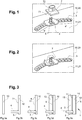
Fig. 1 ] lafigure 1 est une vue en perspective d'un élément pour pièce de carrosserie selon l'invention en cours de fabrication ; - [
Fig. 2 ] lafigure 2 est une vue en perspective de l'élément pour pièce de carrosserie de lafigure 1 équipé d'un moyen de protection ; - [
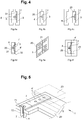
Fig. 3 ] lafigure 3 est un ensemble de schémas (figures 3a-3e ) illustrant différentes étapes du procédé de fabrication de l'élément pour carrosserie selon un premier mode de réalisation ; - [
Fig. 4 ] lafigure 4 est un ensemble de schémas (figures 4a-4f ) illustrant différentes étapes du procédé de fabrication de l'élément pour carrosserie selon un second mode de réalisation ; - [
Fig. 5 ] lafigure 5 est une vue en perspective de l'élément pour carrosserie partiellement coupé selon un plan orthogonal à la feuille support obtenu selon le second mode de réalisation. - On a représenté sur les
figures 1 et 2 un élément pour pièce de carrosserie désigné par la référence générale 1 qui est en cours de fabrication selon le procédé tel que proposé par la présente invention. Le procédé de fabrication comprend une première étape à laquelle on réalise un élément de support 10 ou 20 présentant une première face 11, 21 sur laquelle est fixé une feuille support 3 comprenant au moins un organe de connexion 4. L'organe de connexion 4 est formé d'une plaque conductrice de l'électricité. L'organe de connexion 4 permettra de raccorder au moins une piste chauffante 5 à une source d'énergie. Comme cela sera décrit par la suite, la feuille de support 3 peut comprendre un ou des éléments de connexion 4' connectés entre eux et à l'organe de connexion 4, chaque élément de connexion 4' pourra être relié à une piste chauffante 5. Les différentes possibilités de réalisation de circuits électriques reliant les différents éléments susmentionnés, bien connues de l'homme du métier, ne feront pas l'objet d'une description détaillée dans la présente demande. - Deux modes de réalisation sont illustrés respectivement aux
figures 3 et4 et seront décrits en détail plus loin. Dans les deux modes de réalisation, on dispose une piste chauffante 5 sur l'élément de support 10, 20, la piste chauffante 5 étant disposée sur la première face 11 ou 21 de l'élément de support 10 ou 20, la piste chauffante 5 pouvant être formée d'un fil conducteur de l'électricité. Ensuite, on raccorde la piste chauffante 5 à l'organe de connexion 4 (par exemple par soudure à l'étain) et on dispose l'élément de support 10 ou 20 dans une chambre de moulage d'un moule définissant la forme de l'élément pour pièce de carrosserie, la première face 11 ou 21 de l'élément de support 10, 20 étant face à l'intérieur de la chambre de moulage et on injecte une matière plastique dans la chambre de moulage afin de recouvrir la piste chauffante 5. - Lors de cette injection, il est possible de placer un moyen de protection 7 de l'organe de connexion 4 autour de ce dernier pour le protéger de la matière plastique injectée en l'isolant pour par la suite garantir son accès pour le raccorder à un moyen d'alimentation électrique.
- Avantageusement, le moyen de protection 7 est l'embase connectique permettant de réaliser le raccordement de l'organe de connexion 4 à un moyen d'alimentation électrique en accueillant un connecteur (non illustré). Ainsi, l'ensemble formé comprend déjà un moyen permettant la fixation d'un connecteur.
- Dans le cas où le moyen de protection 7 comprend une ouverture permettant de relier l'organe de connexion 4 à un connecteur (par exemple si l'organe de protection 7 est une embase connectique comprenant une paroi (ou fût) 72 entourant l'organe de connexion '), le moule dans lequel la matière plastique est injectée comprend un logement 8 (numérotée sur la
figure 4a ) dans lequel la paroi 72 vient se loger de manière à obturer l'ouverture et ainsi empêcher l'entrée de matière plastique à l'intérieur du moyen de protection 7 et recouvrant alors l'organe de connexion 4 grâce à un ajustement entre la paroi 72 et le logement 8. - Comme cela sera décrit par la suite, le nombre de moulage peut varier selon le mode de réalisation. Dès lors, il est possible de reproduire cette configuration d'obturation de l'ouverture dans le logement 8 à chaque moulage pour protéger l'organe de connexion 4.
- Maintenant, on va décrire le premier mode de réalisation qui est visible aux
figures 3a-3e . Selon ce mode de réalisation, l'élément de support 10 est un film en matière plastique comme illustré à lafigure 3a . On peut réaliser ce film par extrusion ou laminage avant de fixer une feuille support 3 comprenant au moins un organe de connexion 4 sur une première face 11 du film comme illustré à lafigure 3b . Il est également envisageable d'utiliser un film existant sur le marché. Le film forme une première couche transparente. - Tel que visible à la
figure 3c , on dispose une piste chauffante 5 sur le film, la piste chauffante 5 étant disposée sur la première face 11 de l'élément de support 10. Ensuite, on raccorde la piste chauffante 5 à l'organe de connexion 4, par soudure par exemple. La piste chauffante 5 est répartie de façon homogène sur toute la surface du film et y est fixée par collage ou par fusion locale du film. - Une étape de moulage est ensuite réalisée dans laquelle on dispose l'élément de support 10 dans une chambre de moulage d'un moule définissant la forme de l'élément pour pièce de carrosserie, la première face 11 de l'élément de support 10 étant face à l'intérieur de la chambre de moulage et on injecte une matière plastique dans la chambre de moulage afin de recouvrir la piste chauffante 5. On obtient ainsi une seconde couche transparente 13 tel qu'illustré par la
figure 3d . La chambre de moulage de l'élément pour pièce de carrosserie est configurée de façon à ce qu'après le moulage, l'organe de connexion 4 soit accessible par un moyen d'alimentation électrique. Ainsi, l'épaisseur de la seconde couche 13 transparente est inférieure à celle de l'organe de connexion 4. C'est également lors de cette étape qu'une protection de l'organe de connexion 4 par un moyen de protection 7 telle que décrite plus haut est envisageable en plaçant avant cette étape ledit moyen de protection 7. - Afin d'améliorer la résistance de l'élément aux UV et de le protéger de la rayure, il est possible de déposer un revêtement 6 sur une seconde face 12 du film qui est opposée à la première face 11 comme montré à la
figure 3e . Cette étape est également envisageable dans le second mode de réalisation qui est illustré auxfigures 4 et 5 . - Selon le second mode de réalisation de la présente invention, l'élément de support 20 est une pièce moulée formant une première couche transparente qui est obtenu par les étapes suivantes : on dispose une feuille support 3 comprenant au moins un organe de connexion 4 dans une chambre de moulage d'une moule définissant la forme de la pièce moulée comme visible à la
figure 4a . Une première face 31 de la feuille support 3 est placée face à l'intérieur de la chambre de moulage. A la fermeture du moule, une matière plastique, par exemple un matériau thermoplastique, est injectée dans la chambre de moulage tel que visible à lafigure 4b et on obtient la pièce moulée couvrant la première face 31 de la feuille support 3 comme montré à lafigure 4c . La chambre de moulage de la pièce moulée 20 est configurée de façon à ce que l'épaisseur de la pièce moulée 20 soit inférieure à celle de l'organe de connexion 4 pour que ce dernier soit accessible par un moyen d'alimentation électrique. Comme cela est visible sur lesfigure 4a à 4c , il est possible de placer le moyen de protection 7 autour de l'organe de protection 4 au lors de ce premier moulage pour l'isoler de la matière injectée comme expliqué plus haut. - Par la suite, tel que visible à la
figure 4d , on dispose plusieurs éléments de connexion 4' sur une seconde face 32 de la feuille support 3 qui est opposée à la première face 31, les éléments de connexion 4' étant reliés électriquement entre eux par des moyens de connexion intégrés dans la feuille support 3. Tous les éléments de connexion 4' sont également reliés à l'organe de connexion 4 qui se trouve sur la première face 31. - Après le surmoulage de la première couche transparente (ou élément de support 20) et comme visible à la
figure 4e , des pistes chauffantes 5 sont disposées sur la première couche et raccordées chacune à un élément de connexion 4' sur la seconde face 32 de la feuille support 3 par soudure. Il peut par exemple s'agir de plusieurs fils tels que décrits plus haut formant une zone chauffante (cette configuration à plusieurs éléments de connexion 4' et plusieurs pistes chauffantes 5 est également envisageables pour le premier mode de réalisation de l'invention). Les pistes chauffantes 5 sont réparties de façon homogène sur toute la surface de la première couche transparente et y sont fixées par collage ou par fusion locale de la première couche. - Enfin, l'ensemble comprenant la première couche, la feuille support 3 et les pistes chauffantes 5 est placé dans une chambre de moulage définissant la forme de l'élément pour pièce de carrosserie, la première face 21 de l'élément de support 20 étant face à l'intérieur de la chambre de moulage. Une autre matière plastique, par exemple du polyuréthane thermoplastique (TPU), est injectée dans la chambre de moulage afin de recouvrir les pistes chauffante 5 comme illustré à la
figure 4f . Là encore, le moyen de protection 7 peut protéger l'organe de connexion 4 (par exemple, l'ouverture du moyen de protection 7 peut de nouveau être placée dans l'encoche 8). - Selon le premier ou le second mode de réalisation, on obtient un élément 1 pour pièce de carrosserie comprenant une première couche en plastique transparente (correspondant à l'élément de support 10 ou 20), une seconde couche 13, 23 en plastique transparente, au moins une piste chauffante 5 agencée entre les couches en plastique transparente et reliée à un organe de connexion 4, la piste chauffante 5 étant en contact direct avec les première et seconde couches.
- Un tel élément 1 obtenu par le procédé de fabrication selon le second mode de réalisation est visible à la
figure 5 qui illustre un autre aspect de l'invention concernant un moyen de protection 7 de l'organe de connexion. Le moyen de protection 7 tel qu'il est illustré également auxfigures 1 et 2 comprend une base 71 destinée à prendre appui contre la feuille support 3 et une paroi 72 s'étendant depuis la base 71 et définissant un espace destiné à contenir au moins partiellement l'organe de connexion 4 de façon à ce que celui-ci soit isolé de la matière plastique injectée pendant le moulage tout en lui gardant un accès pour le branchement à une alimentation électrique. - L'invention n'est pas limitée aux modes de réalisation présentés et d'autres modes de réalisation apparaîtront clairement à l'homme du métier. Il est notamment possible d'agencer plusieurs organes de connexion dans le premier mode de réalisation et de les relier électriquement ensemble. Il est également possible de prévoir un anneau ou une zone technique opaque permettant de cacher la feuille supporte lorsque l'élément est assemblé sur le véhicule.
-
- 1 : élément
- 10, 20 : élément de support (première couche)
- 13, 23 : seconde couche
- 11, 21 : première face de l'élément de support
- 12 : seconde face de l'élément de support
- 3 : feuille de support
- 31 : première face de la feuille support
- 32 : seconde face de la feuille support
- 4, : organe de connexion
- 4' : éléments de connexion
- 5 : piste chauffante
- 7 : moyen de protection
- 71 : base du moyen de protection
- 72 : paroi du moyen de protection
- 8 : logement
Claims (11)
- Procédé de fabrication d'un élément (1) pour pièce de carrosserie comprenant successivement les étapes suivantes :- Étape A : on réalise un élément de support (10, 20) présentant une première face (11, 21) sur laquelle est fixée une feuille support (3) comprenant au moins un organe de connexion (4).- Étape B : on dispose au moins une piste chauffante (5) sur l'élément de support (10, 20), la piste chauffante (5) étant disposée sur la première face (11, 21) de l'élément de support (10, 20),- Étape C : on raccorde la piste chauffante (5) à l'organe de connexion (4),- Étape D : on dispose l'élément de support (10, 20) dans une chambre de moulage d'un moule définissant la forme de l'élément pour pièce de carrosserie, la première face (11, 21) de l'élément de support (10, 20) étant face à l'intérieur de la chambre de moulage et on injecte une matière plastique dans la chambre de moulage afin de recouvrir la piste chauffante (5).
- Procédé de fabrication selon la revendication 1 dans lequel l'élément de support (10) est un film en matière plastique et l'étape A comprend les étapes suivantes :- on réalise un film en matière plastique,- on fixe sur une première face du film une feuille support (3) comprenant au moins un organe de connexion (4).
- Procédé de fabrication selon l'une quelconque des revendications précédentes comprenant l'étape suivante :- on dépose un revêtement (6) sur une seconde face (12) de l'élément de support (10, 20), opposée à la première face (11).
- Procédé de fabrication selon la revendication 1 dans lequel l'élément de support (20) est une pièce moulée et l'étape A comprend les étapes suivantes :- on dispose une feuille support (3) comprenant au moins un organe de connexion (4) dans une chambre de moulage d'un moule définissant la forme de l'élément de support (20), une première face (31) de la feuille support (3) étant face à l'intérieur de la chambre de moulage, et on injecte une matière plastique dans la chambre de moulage afin d'obtenir une pièce moulée couvrant la première face (31) de la feuille support (3),- On dispose sur une seconde face (32) de la feuille support (3), opposée à la première face (31), au moins un élément de connexion (4').
- Procédé de fabrication selon l'une quelconque des revendications précédentes comprenant l'étape suivante avant l'étape D :- On dispose sur la feuille support un moyen de protection (7) de l'organe de connexion (4) de façon à protéger au moins partiellement l'organe de connexion (4) de la matière plastique pendant l'étape D.
- Procédé de fabrication selon l'une quelconque des revendications précédentes dans lequel la piste chauffante (5) est raccordée à l'organe de connexion (4) par soudure.
- Procédé de fabrication selon l'une quelconque des revendications précédentes dans lequel la feuille support (3) comprend une pluralité d'éléments de connexion (4') reliés électriquement entre eux par des moyens de connexion intégrés dans la feuille support (3) et les étapes B et C consistent à disposer un nombre correspondant de piste chauffante (5) sur l'élément de support (10, 20) et à raccorder chaque piste chauffante (5) à un élément de connexion (4').
- Procédé de fabrication selon l'une quelconque des revendications précédentes dans lequel on fixe la piste chauffante (5) sur l'élément de support (10, 20) par collage ou par fusion locale de l'élément de support (10, 20).
- Procédé de fabrication selon l'une quelconque des revendications précédentes dans lequel la piste chauffante (5) comprend un matériau choisi parmi du cuivre, du tungstène, ou un alliage de cuivre et de tungstène.
- Procédé de fabrication selon l'une quelconque des revendications précédentes dans lequel la feuille de support (3) est réalisée à partir d'une feuille de silicone, de polyoléfine (polyéthylène ou polypropylène), d'élastomère thermoplastique (TPE), de polyester, ou de polyamide.
- Élément pour pièce de carrosserie comprenant une première couche en plastique transparente, une seconde couche (13, 23) en plastique transparente, une piste chauffante (5) agencée entre les couches en plastique transparente et reliée à un organe de connexion (4), la piste chauffante (5) étant en contact direct avec les première et seconde couches.
Applications Claiming Priority (1)
| Application Number | Priority Date | Filing Date | Title |
|---|---|---|---|
| FR1908631A FR3099400B1 (fr) | 2019-07-29 | 2019-07-29 | Élément pour pièce de carrosserie comportant un film chauffant |
Publications (2)
| Publication Number | Publication Date |
|---|---|
| EP3782790A1 true EP3782790A1 (fr) | 2021-02-24 |
| EP3782790B1 EP3782790B1 (fr) | 2022-09-07 |
Family
ID=68654698
Family Applications (1)
| Application Number | Title | Priority Date | Filing Date |
|---|---|---|---|
| EP20188057.2A Active EP3782790B1 (fr) | 2019-07-29 | 2020-07-28 | Procédé pour pièce de carrosserie comportant un film chauffant |
Country Status (4)
| Country | Link |
|---|---|
| US (1) | US11877357B2 (fr) |
| EP (1) | EP3782790B1 (fr) |
| CN (1) | CN112310634B (fr) |
| FR (1) | FR3099400B1 (fr) |
Families Citing this family (5)
| Publication number | Priority date | Publication date | Assignee | Title |
|---|---|---|---|---|
| EP4090131A1 (fr) * | 2021-05-13 | 2022-11-16 | Yanfeng Plastic Omnium Automotive Exterior Systems Co., Ltd. | Module de chauffage de dégivrage pour automobile |
| EP4122670A1 (fr) * | 2021-07-23 | 2023-01-25 | Weißer und Grießhaber Gesellschaft mit beschränkter Haftung | Procédé de fabrication d'un recouvrement en matière plastique doté d'une piste électroconductrice |
| AT526302B1 (de) * | 2022-06-21 | 2024-12-15 | Att Advanced Thermal Tech Gmbh | Schutzabdeckung für Sensoren der Fahrzeugtechnik |
| WO2025174788A1 (fr) * | 2024-02-13 | 2025-08-21 | Covestro Llc | Moulage par insertion et revêtement dans un moule sur des substrats comportant des éléments sensibles à la pression |
| DE102024109457A1 (de) * | 2024-04-04 | 2025-10-09 | Oechsler Ag | Verfahren zur Herstellung eines Vorspritzlings und/oder eines Radoms für Radarvorrichtungen für Fahrzeuge |
Citations (3)
| Publication number | Priority date | Publication date | Assignee | Title |
|---|---|---|---|---|
| US20180269569A1 (en) | 2015-09-30 | 2018-09-20 | HELLA GmbH & Co. KGaA | Method for producing a radome and corresponding radome |
| DE102018007404A1 (de) * | 2017-09-25 | 2019-03-28 | Compagnie Plastic Omnium | Verfahren zur Herstellung eines Fahrzeugbauteils aus Kunststoff mit mindestens einer spritzgegossenen Heizbahn |
| FR3075720A1 (fr) * | 2017-12-21 | 2019-06-28 | Compagnie Plastic Omnium | Piece de carrosserie comprenant un element de decoration et un moyen chauffant |
Family Cites Families (5)
| Publication number | Priority date | Publication date | Assignee | Title |
|---|---|---|---|---|
| EP2145506B1 (fr) * | 2007-05-01 | 2013-04-24 | Exatec, LLC. | Connexions électriques pour fenêtres en plastique moulées d'insert de film |
| CN102077060B (zh) * | 2008-06-04 | 2014-10-29 | G·帕特尔 | 一种基于腐蚀金属的监测系统 |
| DE102013012785A1 (de) * | 2013-07-31 | 2015-02-05 | Daimler Ag | Herstellverfahren für ein Kunststoff-Radom eines Kraftfahrzeugs |
| JP6540611B2 (ja) * | 2016-06-15 | 2019-07-10 | 株式会社豊田自動織機 | 樹脂ウィンドウの製造方法及び樹脂ウィンドウ |
| DE102018132395A1 (de) * | 2018-12-17 | 2020-06-18 | Bayerische Motoren Werke Aktiengesellschaft | Verfahren zur Herstellung einer Flächenheizung für einen Teilbereich eines Fahrzeugs |
-
2019
- 2019-07-29 FR FR1908631A patent/FR3099400B1/fr not_active Expired - Fee Related
-
2020
- 2020-07-28 EP EP20188057.2A patent/EP3782790B1/fr active Active
- 2020-07-29 US US16/941,795 patent/US11877357B2/en active Active
- 2020-07-29 CN CN202010742741.2A patent/CN112310634B/zh active Active
Patent Citations (3)
| Publication number | Priority date | Publication date | Assignee | Title |
|---|---|---|---|---|
| US20180269569A1 (en) | 2015-09-30 | 2018-09-20 | HELLA GmbH & Co. KGaA | Method for producing a radome and corresponding radome |
| DE102018007404A1 (de) * | 2017-09-25 | 2019-03-28 | Compagnie Plastic Omnium | Verfahren zur Herstellung eines Fahrzeugbauteils aus Kunststoff mit mindestens einer spritzgegossenen Heizbahn |
| FR3075720A1 (fr) * | 2017-12-21 | 2019-06-28 | Compagnie Plastic Omnium | Piece de carrosserie comprenant un element de decoration et un moyen chauffant |
Also Published As
| Publication number | Publication date |
|---|---|
| EP3782790B1 (fr) | 2022-09-07 |
| FR3099400B1 (fr) | 2021-07-30 |
| US11877357B2 (en) | 2024-01-16 |
| CN112310634A (zh) | 2021-02-02 |
| CN112310634B (zh) | 2025-07-18 |
| FR3099400A1 (fr) | 2021-02-05 |
| US20210037610A1 (en) | 2021-02-04 |
Similar Documents
| Publication | Publication Date | Title |
|---|---|---|
| EP3782790B1 (fr) | Procédé pour pièce de carrosserie comportant un film chauffant | |
| EP3766677B1 (fr) | Procédé de fabrication d'un élément de carrosserie muni d'une piste conductrice | |
| EP1247696B1 (fr) | Elément extérieur de véhicule automobile, intégrant un capteur capacitif et pièce de carrosserie comportant un tel élément extérieur | |
| FR2826626A1 (fr) | Module d'equipement d'un vehicule automobile | |
| EP3772133B1 (fr) | Dispositif de protection pour lidar de véhicule automobile | |
| CN110875510B (zh) | 车辆雷达罩及用于制造所述雷达罩的方法 | |
| EP1550579B1 (fr) | Dispositif d'éclairage intérieur pour véhicule automobile | |
| FR2864700A1 (fr) | Procede d'enrobage d'une unite electronique d'un capteur et capteur correspondant | |
| WO2019202154A1 (fr) | Procede de fabrication d'un element pour piece de carrosserie comportant des moyens de degivrage perfectionnes | |
| EP0323295B1 (fr) | Procédé pour fixer sur un support un composant électronique et ses contacts | |
| EP3769952A1 (fr) | Élément de pièce de carrosserie dégivrant | |
| FR3101008A1 (fr) | Procédé de fabrication d’un élément pour pièce de carrosserie | |
| FR3014388A1 (fr) | Procede de fabrication d'un element chauffant pour balai d'essuie-glace d'un vehicule | |
| FR2801728A1 (fr) | Antenne emettrice de champ magnetique pour vehicule automobile | |
| EP3756852B1 (fr) | Procédé de fabrication d'une pièce de carrosserie comprenant un dispositif électrique | |
| WO2020099057A1 (fr) | Élément de pièce de carrosserie comportant un film chauffant | |
| FR3026672A1 (fr) | Procede de fabrication d'une structure de vehicule ayant deux composants en materiau thermoplastique colles par chauffage, et structure de vehicule correspondante | |
| FR3099411A1 (fr) | Panneau de commande pour véhicule et procédé de réalisation | |
| FR3075454B1 (fr) | Element du type capteur surmoule et son procede de fabrication, et son procede de montage pour sa connexion electrique | |
| EP2824704A1 (fr) | Module électronique et son procédé de fabrication | |
| WO2016008798A1 (fr) | Dispositif et procédé de connexion d'un moteur électrique | |
| FR3082802A1 (fr) | Piece d'habillage interieur pour habitacle de vehicule et procede de fabrication de la piece d'habillage interieur | |
| FR3154673A1 (fr) | Pièce de garniture ou d’équipement de véhicule intégrant un élément fonctionnel électrique, procédé et installations pour sa fabrication | |
| EP1399975B1 (fr) | Capteur de luminosite et son procede de fabrication | |
| EP0915431A1 (fr) | Carte à microcircuit et procédé de fabrication d'une telle carte |
Legal Events
| Date | Code | Title | Description |
|---|---|---|---|
| PUAI | Public reference made under article 153(3) epc to a published international application that has entered the european phase |
Free format text: ORIGINAL CODE: 0009012 |
|
| STAA | Information on the status of an ep patent application or granted ep patent |
Free format text: STATUS: THE APPLICATION HAS BEEN PUBLISHED |
|
| AK | Designated contracting states |
Kind code of ref document: A1 Designated state(s): AL AT BE BG CH CY CZ DE DK EE ES FI FR GB GR HR HU IE IS IT LI LT LU LV MC MK MT NL NO PL PT RO RS SE SI SK SM TR |
|
| AX | Request for extension of the european patent |
Extension state: BA ME |
|
| RIN1 | Information on inventor provided before grant (corrected) |
Inventor name: DUBOST, ELISE Inventor name: STABLO, FREDERIC Inventor name: TRESSE, DAVID Inventor name: BOISSON, DAMIEN Inventor name: JACQUEMET, THIERRY Inventor name: SELMANE, ISMAEL |
|
| STAA | Information on the status of an ep patent application or granted ep patent |
Free format text: STATUS: REQUEST FOR EXAMINATION WAS MADE |
|
| 17P | Request for examination filed |
Effective date: 20210722 |
|
| RBV | Designated contracting states (corrected) |
Designated state(s): AL AT BE BG CH CY CZ DE DK EE ES FI FR GB GR HR HU IE IS IT LI LT LU LV MC MK MT NL NO PL PT RO RS SE SI SK SM TR |
|
| GRAP | Despatch of communication of intention to grant a patent |
Free format text: ORIGINAL CODE: EPIDOSNIGR1 |
|
| STAA | Information on the status of an ep patent application or granted ep patent |
Free format text: STATUS: GRANT OF PATENT IS INTENDED |
|
| RIC1 | Information provided on ipc code assigned before grant |
Ipc: H05B 3/18 20060101ALI20220406BHEP Ipc: H05B 3/16 20060101ALI20220406BHEP Ipc: H01Q 1/02 20060101ALI20220406BHEP Ipc: B29C 45/14 20060101AFI20220406BHEP |
|
| INTG | Intention to grant announced |
Effective date: 20220422 |
|
| GRAS | Grant fee paid |
Free format text: ORIGINAL CODE: EPIDOSNIGR3 |
|
| GRAA | (expected) grant |
Free format text: ORIGINAL CODE: 0009210 |
|
| STAA | Information on the status of an ep patent application or granted ep patent |
Free format text: STATUS: THE PATENT HAS BEEN GRANTED |
|
| AK | Designated contracting states |
Kind code of ref document: B1 Designated state(s): AL AT BE BG CH CY CZ DE DK EE ES FI FR GB GR HR HU IE IS IT LI LT LU LV MC MK MT NL NO PL PT RO RS SE SI SK SM TR |
|
| REG | Reference to a national code |
Ref country code: GB Ref legal event code: FG4D Free format text: NOT ENGLISH |
|
| REG | Reference to a national code |
Ref country code: CH Ref legal event code: EP Ref country code: AT Ref legal event code: REF Ref document number: 1516666 Country of ref document: AT Kind code of ref document: T Effective date: 20220915 |
|
| REG | Reference to a national code |
Ref country code: DE Ref legal event code: R096 Ref document number: 602020004943 Country of ref document: DE |
|
| REG | Reference to a national code |
Ref country code: IE Ref legal event code: FG4D Free format text: LANGUAGE OF EP DOCUMENT: FRENCH |
|
| REG | Reference to a national code |
Ref country code: LT Ref legal event code: MG9D |
|
| REG | Reference to a national code |
Ref country code: NL Ref legal event code: MP Effective date: 20220907 |
|
| PG25 | Lapsed in a contracting state [announced via postgrant information from national office to epo] |
Ref country code: SE Free format text: LAPSE BECAUSE OF FAILURE TO SUBMIT A TRANSLATION OF THE DESCRIPTION OR TO PAY THE FEE WITHIN THE PRESCRIBED TIME-LIMIT Effective date: 20220907 Ref country code: RS Free format text: LAPSE BECAUSE OF FAILURE TO SUBMIT A TRANSLATION OF THE DESCRIPTION OR TO PAY THE FEE WITHIN THE PRESCRIBED TIME-LIMIT Effective date: 20220907 Ref country code: NO Free format text: LAPSE BECAUSE OF FAILURE TO SUBMIT A TRANSLATION OF THE DESCRIPTION OR TO PAY THE FEE WITHIN THE PRESCRIBED TIME-LIMIT Effective date: 20221207 Ref country code: LV Free format text: LAPSE BECAUSE OF FAILURE TO SUBMIT A TRANSLATION OF THE DESCRIPTION OR TO PAY THE FEE WITHIN THE PRESCRIBED TIME-LIMIT Effective date: 20220907 Ref country code: LT Free format text: LAPSE BECAUSE OF FAILURE TO SUBMIT A TRANSLATION OF THE DESCRIPTION OR TO PAY THE FEE WITHIN THE PRESCRIBED TIME-LIMIT Effective date: 20220907 Ref country code: FI Free format text: LAPSE BECAUSE OF FAILURE TO SUBMIT A TRANSLATION OF THE DESCRIPTION OR TO PAY THE FEE WITHIN THE PRESCRIBED TIME-LIMIT Effective date: 20220907 |
|
| REG | Reference to a national code |
Ref country code: AT Ref legal event code: MK05 Ref document number: 1516666 Country of ref document: AT Kind code of ref document: T Effective date: 20220907 |
|
| PG25 | Lapsed in a contracting state [announced via postgrant information from national office to epo] |
Ref country code: HR Free format text: LAPSE BECAUSE OF FAILURE TO SUBMIT A TRANSLATION OF THE DESCRIPTION OR TO PAY THE FEE WITHIN THE PRESCRIBED TIME-LIMIT Effective date: 20220907 Ref country code: GR Free format text: LAPSE BECAUSE OF FAILURE TO SUBMIT A TRANSLATION OF THE DESCRIPTION OR TO PAY THE FEE WITHIN THE PRESCRIBED TIME-LIMIT Effective date: 20221208 |
|
| PG25 | Lapsed in a contracting state [announced via postgrant information from national office to epo] |
Ref country code: SM Free format text: LAPSE BECAUSE OF FAILURE TO SUBMIT A TRANSLATION OF THE DESCRIPTION OR TO PAY THE FEE WITHIN THE PRESCRIBED TIME-LIMIT Effective date: 20220907 Ref country code: RO Free format text: LAPSE BECAUSE OF FAILURE TO SUBMIT A TRANSLATION OF THE DESCRIPTION OR TO PAY THE FEE WITHIN THE PRESCRIBED TIME-LIMIT Effective date: 20220907 Ref country code: PT Free format text: LAPSE BECAUSE OF FAILURE TO SUBMIT A TRANSLATION OF THE DESCRIPTION OR TO PAY THE FEE WITHIN THE PRESCRIBED TIME-LIMIT Effective date: 20230109 Ref country code: ES Free format text: LAPSE BECAUSE OF FAILURE TO SUBMIT A TRANSLATION OF THE DESCRIPTION OR TO PAY THE FEE WITHIN THE PRESCRIBED TIME-LIMIT Effective date: 20220907 Ref country code: CZ Free format text: LAPSE BECAUSE OF FAILURE TO SUBMIT A TRANSLATION OF THE DESCRIPTION OR TO PAY THE FEE WITHIN THE PRESCRIBED TIME-LIMIT Effective date: 20220907 Ref country code: AT Free format text: LAPSE BECAUSE OF FAILURE TO SUBMIT A TRANSLATION OF THE DESCRIPTION OR TO PAY THE FEE WITHIN THE PRESCRIBED TIME-LIMIT Effective date: 20220907 |
|
| PG25 | Lapsed in a contracting state [announced via postgrant information from national office to epo] |
Ref country code: SK Free format text: LAPSE BECAUSE OF FAILURE TO SUBMIT A TRANSLATION OF THE DESCRIPTION OR TO PAY THE FEE WITHIN THE PRESCRIBED TIME-LIMIT Effective date: 20220907 Ref country code: PL Free format text: LAPSE BECAUSE OF FAILURE TO SUBMIT A TRANSLATION OF THE DESCRIPTION OR TO PAY THE FEE WITHIN THE PRESCRIBED TIME-LIMIT Effective date: 20220907 Ref country code: IS Free format text: LAPSE BECAUSE OF FAILURE TO SUBMIT A TRANSLATION OF THE DESCRIPTION OR TO PAY THE FEE WITHIN THE PRESCRIBED TIME-LIMIT Effective date: 20230107 Ref country code: EE Free format text: LAPSE BECAUSE OF FAILURE TO SUBMIT A TRANSLATION OF THE DESCRIPTION OR TO PAY THE FEE WITHIN THE PRESCRIBED TIME-LIMIT Effective date: 20220907 |
|
| REG | Reference to a national code |
Ref country code: DE Ref legal event code: R097 Ref document number: 602020004943 Country of ref document: DE |
|
| P01 | Opt-out of the competence of the unified patent court (upc) registered |
Effective date: 20230517 |
|
| PG25 | Lapsed in a contracting state [announced via postgrant information from national office to epo] |
Ref country code: NL Free format text: LAPSE BECAUSE OF FAILURE TO SUBMIT A TRANSLATION OF THE DESCRIPTION OR TO PAY THE FEE WITHIN THE PRESCRIBED TIME-LIMIT Effective date: 20220907 Ref country code: AL Free format text: LAPSE BECAUSE OF FAILURE TO SUBMIT A TRANSLATION OF THE DESCRIPTION OR TO PAY THE FEE WITHIN THE PRESCRIBED TIME-LIMIT Effective date: 20220907 |
|
| PLBE | No opposition filed within time limit |
Free format text: ORIGINAL CODE: 0009261 |
|
| STAA | Information on the status of an ep patent application or granted ep patent |
Free format text: STATUS: NO OPPOSITION FILED WITHIN TIME LIMIT |
|
| PG25 | Lapsed in a contracting state [announced via postgrant information from national office to epo] |
Ref country code: DK Free format text: LAPSE BECAUSE OF FAILURE TO SUBMIT A TRANSLATION OF THE DESCRIPTION OR TO PAY THE FEE WITHIN THE PRESCRIBED TIME-LIMIT Effective date: 20220907 |
|
| 26N | No opposition filed |
Effective date: 20230608 |
|
| PG25 | Lapsed in a contracting state [announced via postgrant information from national office to epo] |
Ref country code: SI Free format text: LAPSE BECAUSE OF FAILURE TO SUBMIT A TRANSLATION OF THE DESCRIPTION OR TO PAY THE FEE WITHIN THE PRESCRIBED TIME-LIMIT Effective date: 20220907 |
|
| PG25 | Lapsed in a contracting state [announced via postgrant information from national office to epo] |
Ref country code: MC Free format text: LAPSE BECAUSE OF FAILURE TO SUBMIT A TRANSLATION OF THE DESCRIPTION OR TO PAY THE FEE WITHIN THE PRESCRIBED TIME-LIMIT Effective date: 20220907 |
|
| PG25 | Lapsed in a contracting state [announced via postgrant information from national office to epo] |
Ref country code: MC Free format text: LAPSE BECAUSE OF FAILURE TO SUBMIT A TRANSLATION OF THE DESCRIPTION OR TO PAY THE FEE WITHIN THE PRESCRIBED TIME-LIMIT Effective date: 20220907 |
|
| REG | Reference to a national code |
Ref country code: CH Ref legal event code: PL |
|
| REG | Reference to a national code |
Ref country code: BE Ref legal event code: MM Effective date: 20230731 |
|
| PG25 | Lapsed in a contracting state [announced via postgrant information from national office to epo] |
Ref country code: LU Free format text: LAPSE BECAUSE OF NON-PAYMENT OF DUE FEES Effective date: 20230728 |
|
| PG25 | Lapsed in a contracting state [announced via postgrant information from national office to epo] |
Ref country code: LU Free format text: LAPSE BECAUSE OF NON-PAYMENT OF DUE FEES Effective date: 20230728 |
|
| REG | Reference to a national code |
Ref country code: IE Ref legal event code: MM4A |
|
| PG25 | Lapsed in a contracting state [announced via postgrant information from national office to epo] |
Ref country code: CH Free format text: LAPSE BECAUSE OF NON-PAYMENT OF DUE FEES Effective date: 20230731 |
|
| PG25 | Lapsed in a contracting state [announced via postgrant information from national office to epo] |
Ref country code: IT Free format text: LAPSE BECAUSE OF FAILURE TO SUBMIT A TRANSLATION OF THE DESCRIPTION OR TO PAY THE FEE WITHIN THE PRESCRIBED TIME-LIMIT Effective date: 20220907 Ref country code: BE Free format text: LAPSE BECAUSE OF NON-PAYMENT OF DUE FEES Effective date: 20230731 |
|
| PG25 | Lapsed in a contracting state [announced via postgrant information from national office to epo] |
Ref country code: IE Free format text: LAPSE BECAUSE OF NON-PAYMENT OF DUE FEES Effective date: 20230728 |
|
| PG25 | Lapsed in a contracting state [announced via postgrant information from national office to epo] |
Ref country code: IE Free format text: LAPSE BECAUSE OF NON-PAYMENT OF DUE FEES Effective date: 20230728 |
|
| REG | Reference to a national code |
Ref country code: DE Ref legal event code: R081 Ref document number: 602020004943 Country of ref document: DE Owner name: OPMOBILITY SE, FR Free format text: FORMER OWNER: COMPAGNIE PLASTIC OMNIUM SE, LYON, FR |
|
| PG25 | Lapsed in a contracting state [announced via postgrant information from national office to epo] |
Ref country code: BG Free format text: LAPSE BECAUSE OF FAILURE TO SUBMIT A TRANSLATION OF THE DESCRIPTION OR TO PAY THE FEE WITHIN THE PRESCRIBED TIME-LIMIT Effective date: 20220907 |
|
| PG25 | Lapsed in a contracting state [announced via postgrant information from national office to epo] |
Ref country code: BG Free format text: LAPSE BECAUSE OF FAILURE TO SUBMIT A TRANSLATION OF THE DESCRIPTION OR TO PAY THE FEE WITHIN THE PRESCRIBED TIME-LIMIT Effective date: 20220907 |
|
| GBPC | Gb: european patent ceased through non-payment of renewal fee |
Effective date: 20240728 |
|
| PG25 | Lapsed in a contracting state [announced via postgrant information from national office to epo] |
Ref country code: GB Free format text: LAPSE BECAUSE OF NON-PAYMENT OF DUE FEES Effective date: 20240728 |
|
| PG25 | Lapsed in a contracting state [announced via postgrant information from national office to epo] |
Ref country code: CY Free format text: LAPSE BECAUSE OF FAILURE TO SUBMIT A TRANSLATION OF THE DESCRIPTION OR TO PAY THE FEE WITHIN THE PRESCRIBED TIME-LIMIT; INVALID AB INITIO Effective date: 20200728 |
|
| PG25 | Lapsed in a contracting state [announced via postgrant information from national office to epo] |
Ref country code: HU Free format text: LAPSE BECAUSE OF FAILURE TO SUBMIT A TRANSLATION OF THE DESCRIPTION OR TO PAY THE FEE WITHIN THE PRESCRIBED TIME-LIMIT; INVALID AB INITIO Effective date: 20200728 |
|
| PGFP | Annual fee paid to national office [announced via postgrant information from national office to epo] |
Ref country code: DE Payment date: 20250722 Year of fee payment: 6 |
|
| PGFP | Annual fee paid to national office [announced via postgrant information from national office to epo] |
Ref country code: FR Payment date: 20250730 Year of fee payment: 6 |
|
| PG25 | Lapsed in a contracting state [announced via postgrant information from national office to epo] |
Ref country code: TR Free format text: LAPSE BECAUSE OF FAILURE TO SUBMIT A TRANSLATION OF THE DESCRIPTION OR TO PAY THE FEE WITHIN THE PRESCRIBED TIME-LIMIT Effective date: 20220907 |