EP3782683A1 - System zur atemgasversorgung bei der beatmung mit einem tubus - Google Patents
System zur atemgasversorgung bei der beatmung mit einem tubus Download PDFInfo
- Publication number
- EP3782683A1 EP3782683A1 EP20020380.0A EP20020380A EP3782683A1 EP 3782683 A1 EP3782683 A1 EP 3782683A1 EP 20020380 A EP20020380 A EP 20020380A EP 3782683 A1 EP3782683 A1 EP 3782683A1
- Authority
- EP
- European Patent Office
- Prior art keywords
- pressure
- connection
- balloon
- ventilator
- hose
- Prior art date
- Legal status (The legal status is an assumption and is not a legal conclusion. Google has not performed a legal analysis and makes no representation as to the accuracy of the status listed.)
- Granted
Links
Images


Classifications
-
- A—HUMAN NECESSITIES
- A61—MEDICAL OR VETERINARY SCIENCE; HYGIENE
- A61M—DEVICES FOR INTRODUCING MEDIA INTO, OR ONTO, THE BODY; DEVICES FOR TRANSDUCING BODY MEDIA OR FOR TAKING MEDIA FROM THE BODY; DEVICES FOR PRODUCING OR ENDING SLEEP OR STUPOR
- A61M16/00—Devices for influencing the respiratory system of patients by gas treatment, e.g. ventilators; Tracheal tubes
- A61M16/04—Tracheal tubes
- A61M16/0402—Special features for tracheal tubes not otherwise provided for
- A61M16/0409—Special features for tracheal tubes not otherwise provided for with mean for closing the oesophagus
-
- A—HUMAN NECESSITIES
- A61—MEDICAL OR VETERINARY SCIENCE; HYGIENE
- A61M—DEVICES FOR INTRODUCING MEDIA INTO, OR ONTO, THE BODY; DEVICES FOR TRANSDUCING BODY MEDIA OR FOR TAKING MEDIA FROM THE BODY; DEVICES FOR PRODUCING OR ENDING SLEEP OR STUPOR
- A61M16/00—Devices for influencing the respiratory system of patients by gas treatment, e.g. ventilators; Tracheal tubes
- A61M16/0051—Devices for influencing the respiratory system of patients by gas treatment, e.g. ventilators; Tracheal tubes with alarm devices
-
- A—HUMAN NECESSITIES
- A61—MEDICAL OR VETERINARY SCIENCE; HYGIENE
- A61M—DEVICES FOR INTRODUCING MEDIA INTO, OR ONTO, THE BODY; DEVICES FOR TRANSDUCING BODY MEDIA OR FOR TAKING MEDIA FROM THE BODY; DEVICES FOR PRODUCING OR ENDING SLEEP OR STUPOR
- A61M16/00—Devices for influencing the respiratory system of patients by gas treatment, e.g. ventilators; Tracheal tubes
- A61M16/021—Devices for influencing the respiratory system of patients by gas treatment, e.g. ventilators; Tracheal tubes operated by electrical means
- A61M16/022—Control means therefor
- A61M16/024—Control means therefor including calculation means, e.g. using a processor
-
- A—HUMAN NECESSITIES
- A61—MEDICAL OR VETERINARY SCIENCE; HYGIENE
- A61M—DEVICES FOR INTRODUCING MEDIA INTO, OR ONTO, THE BODY; DEVICES FOR TRANSDUCING BODY MEDIA OR FOR TAKING MEDIA FROM THE BODY; DEVICES FOR PRODUCING OR ENDING SLEEP OR STUPOR
- A61M16/00—Devices for influencing the respiratory system of patients by gas treatment, e.g. ventilators; Tracheal tubes
- A61M16/04—Tracheal tubes
- A61M16/0434—Cuffs
- A61M16/044—External cuff pressure control or supply, e.g. synchronisation with respiration
-
- A—HUMAN NECESSITIES
- A61—MEDICAL OR VETERINARY SCIENCE; HYGIENE
- A61M—DEVICES FOR INTRODUCING MEDIA INTO, OR ONTO, THE BODY; DEVICES FOR TRANSDUCING BODY MEDIA OR FOR TAKING MEDIA FROM THE BODY; DEVICES FOR PRODUCING OR ENDING SLEEP OR STUPOR
- A61M16/00—Devices for influencing the respiratory system of patients by gas treatment, e.g. ventilators; Tracheal tubes
- A61M16/04—Tracheal tubes
- A61M16/0434—Cuffs
- A61M16/045—Cuffs with cuffs partially or completely inflated by the respiratory gas
- A61M16/0452—Cuffs with cuffs partially or completely inflated by the respiratory gas following the inspiration and expiration pressure
-
- A—HUMAN NECESSITIES
- A61—MEDICAL OR VETERINARY SCIENCE; HYGIENE
- A61M—DEVICES FOR INTRODUCING MEDIA INTO, OR ONTO, THE BODY; DEVICES FOR TRANSDUCING BODY MEDIA OR FOR TAKING MEDIA FROM THE BODY; DEVICES FOR PRODUCING OR ENDING SLEEP OR STUPOR
- A61M16/00—Devices for influencing the respiratory system of patients by gas treatment, e.g. ventilators; Tracheal tubes
- A61M16/08—Bellows; Connecting tubes ; Water traps; Patient circuits
- A61M16/0875—Connecting tubes
-
- A—HUMAN NECESSITIES
- A61—MEDICAL OR VETERINARY SCIENCE; HYGIENE
- A61M—DEVICES FOR INTRODUCING MEDIA INTO, OR ONTO, THE BODY; DEVICES FOR TRANSDUCING BODY MEDIA OR FOR TAKING MEDIA FROM THE BODY; DEVICES FOR PRODUCING OR ENDING SLEEP OR STUPOR
- A61M16/00—Devices for influencing the respiratory system of patients by gas treatment, e.g. ventilators; Tracheal tubes
- A61M16/20—Valves specially adapted to medical respiratory devices
-
- A—HUMAN NECESSITIES
- A61—MEDICAL OR VETERINARY SCIENCE; HYGIENE
- A61M—DEVICES FOR INTRODUCING MEDIA INTO, OR ONTO, THE BODY; DEVICES FOR TRANSDUCING BODY MEDIA OR FOR TAKING MEDIA FROM THE BODY; DEVICES FOR PRODUCING OR ENDING SLEEP OR STUPOR
- A61M16/00—Devices for influencing the respiratory system of patients by gas treatment, e.g. ventilators; Tracheal tubes
- A61M16/04—Tracheal tubes
- A61M16/0434—Cuffs
-
- A—HUMAN NECESSITIES
- A61—MEDICAL OR VETERINARY SCIENCE; HYGIENE
- A61M—DEVICES FOR INTRODUCING MEDIA INTO, OR ONTO, THE BODY; DEVICES FOR TRANSDUCING BODY MEDIA OR FOR TAKING MEDIA FROM THE BODY; DEVICES FOR PRODUCING OR ENDING SLEEP OR STUPOR
- A61M2210/00—Anatomical parts of the body
- A61M2210/10—Trunk
- A61M2210/1042—Alimentary tract
- A61M2210/105—Oesophagus
Definitions
- VAP Ventilator-associated pneumonia
- One measure within a package of measures to reduce the VAP risk is the continuous monitoring and control of the blocked balloon of the endotracheal tube or the tracheal cannula.
- the intermittent balloon control using a manometer, used in intensive care units, is widely used. This is to avoid complications in connection with too low or too high balloon pressure. Although this method could theoretically reduce complications, it is inadequate for the long-term maintenance and continuous monitoring of adequate tube blockage.
- the most important function of the tracheal tube balloon is to close the extraluminal airway to air and fluid leakage to enable effective positive pressure mechanical ventilation and to prevent microaspiration of contaminated subglottic secretions. Insufficient pressure in the balloon causes microaspiration. Too much pressure for lesions.
- the object of the invention is to specify an improved and safe system for supplying breathing gas with a tracheal tube balloon.
- a system for breathing gas supply comprising a ventilator, a breathing gas source, a control unit, a pressure control module and / or a flow control module and a memory, with a pressure sensor device and a flow sensor device and a user interface for specifying parameters of the breathing gas supply or for exchanging data are included, wherein the ventilator has at least one hose connection to which the breathing gas hose are adapted can and a patient interface as an interface to the patient and at least one pressure connection for an additional pressure hose, characterized in that a tube is used as the patient interface which has a balloon that can be filled with compressed gas in a defined manner via the pressure connection and the pressure hose adapted to it.
- the system according to the invention is also characterized in that the patient interface is designed as a tube for the windpipe or for the esophagus or as a urinary catheter.
- the system according to the invention is alternatively characterized in that the control unit is set up and designed to control the breathing gas source using the pressure control module or the flow control module for specifying a breathing gas pressure and / or a breathing gas flow, and the breathing gas is provided at the hose connection and passed to a patient via the breathing gas hose becomes.
- the system according to the invention is additionally characterized in that the control unit is set up and designed to additionally activate the humidifier or the nebuliser and the heater for heating and humidifying the breathing gas or an oxygen source at least temporarily.
- the system according to the invention is also characterized in that a pulse oximeter or a co-measuring device is additionally adapted, which then communicates with the system and / or is supplied with energy by it and wherein the control unit is set up and designed to take the measured values of these devices or the user provide at the interface and / or an automatic algorithm to use the correct flow rate and the measured values of these devices or for the activation or control of the oxygen source and / or for the activation or control of the breathing gas source.
- the system according to the invention is alternatively also characterized in that the patient interface is designed as an endotracheal tube with a tracheal end and a distal end, with a tube connector for connection to the breathing gas hose and a continuous lumen for the breathing gases, with the inflatable balloon being formed near the tracheal end , wherein the balloon can be filled with compressed gas from the breathing gas source or a compressed gas source via a supply line which is connected to the pressure connection of the ventilator via the pressure hose.
- the system according to the invention is additionally also characterized in that the control unit is also set up and designed to control the breathing gas source using the pressure control module in such a way that a pressurized gas is fed via a line to the pressure connection of the ventilator, at least one pressure connection being present, and each pressure connection being one Pressure sensor is assigned, which can determine the pressure of the gas in the pressure connection and / or each pressure connection is also assigned a valve which is set up to enable or block a compressed gas flow to the pressure connection.
- the system according to the invention is optionally also characterized in that a user can set the balloon pressure via the interface and the control unit sets the desired pressure in the balloon via the pressure sensor and the pressure regulator, readjusts automatically and uses the balloon pressure (Pbal) as a signal for the control of the ventilator Provides, wherein the balloon pressure (Pbal) is varied, for example, according to the pressure of inspiration and expiration.
- the system according to the invention is, for example, also characterized in that the pressure connection of the ventilator has a connection means for detachable connection to the ventilator, and an inner lumen and a compressed gas line in the inner lumen, as well as a male connector a, which has at least one conical section that is designed for releasable connection with the female receptacle of the pressure adapter.
- the system according to the invention is additionally also characterized in that a pressure adapter is included which has a male Luer connection which is arranged on a short hose section and which has a female receptacle for the male pressure connection of the ventilator, with a check valve in the pressure adapter is arranged, which is biased in a closed position and whose valve body can be moved into an open position by the pressure connection.
- a pressure adapter is included which has a male Luer connection which is arranged on a short hose section and which has a female receptacle for the male pressure connection of the ventilator, with a check valve in the pressure adapter is arranged, which is biased in a closed position and whose valve body can be moved into an open position by the pressure connection.
- the system according to the invention is alternatively also characterized in that a pressure hose is comprised which has a Luer-Lock connection at one end and at least one pressure adapter at the other end which can be plugged onto the pressure connection of the ventilator, with a check valve in the Pressure adapter is arranged, which is biased in a closed position and the valve body in which Connection to the pressure connection, through which the pressure connection is moved into an open position.
- the pressure adapter has a male Luer connection which is arranged on a hose section and which is adapted for connection to a female Luer connection of a pressure hose, the pressure adapter also having a female receptacle for the male Has pressure connection of the ventilator.
- the system according to the invention is also characterized in that a check valve is arranged in the area of the female receptacle, which is pre-tensioned in a closed position by a spring, the valve body of the check valve being movable into an open position through the pressure connection.
- the system according to the invention is also characterized in that the pressure connection has a pressure gas line I which conducts compressed gas and also serves to move the valve body into an open position when the pressure adapter is connected to the pressure connection.
- the system according to the invention is alternatively characterized in that the valve body has a contact surface against which the (tip of the) compressed gas line is pushed when the male pressure connection is pushed into the female receptacle.
- the male pressure connection then presses (by means of the pressure gas line I) the valve body against the spring force into the open position, which enables gas to flow from the male pressure connection into the pressure adapter (or the pressure hose).
- the system according to the invention is, for example, characterized in that the female receptacle is made of a soft or elastomeric material and has an inner lumen which is adapted to the outer diameter of the male pressure connection of the ventilator so that the male pressure connection can be inserted into the female receptacle and a sealing and clamping connection between the two is ensured.
- the pressure adapter can thus be placed on the pressure connection and leads to a sealed flow connection of compressed gas from the pressure connection into the pressure adapter.
- the system according to the invention is alternatively characterized in that the pressure of the balloon is dynamically adapted to the respective pressure situation during inspiration. Especially in patients with high ventilation pressures, this ensures adequate blocking in the endotracheal tube or in the tracheal cannula during inspiration.
- the system according to the invention is also characterized in that the pressure of the balloon is dynamically adapted to the respective pressure situation during expiration. as well as the necessary relief for the blood flow to the tracheal mucosa in the expiratory phase.
- the system according to the invention is alternatively also characterized in that the control unit is also set up and designed to control the breathing gas source using the pressure control module in such a way that compressed gas is fed via a line to the pressure connection of the ventilator, the pressure connection being assigned a pressure sensor that determines the pressure of the gas in the pressure connection, the pressure of the gas in the pressure connection essentially corresponding to the pressure in the balloon (Pbal) when a pressure gas-conducting connection is established between the balloon and the pressure gas connection.
- the system according to the invention is additionally characterized in that the control unit has or controls a pressure regulator in order to set the desired pressure in the balloon and makes the balloon pressure (Pbal) available to the control unit as, for example, a digitized signal.
- the system according to the invention is alternatively also characterized in that the control unit varies the balloon pressure (Pbal) in accordance with the pressure of inspiration and expiration.
- the system according to the invention is also characterized in that the measured balloon pressure is displayed as an additional pressure curve on the ventilator.
- the object is also achieved by a ventilator set up and designed for use in a system according to the invention.
- the object is also achieved by a pressure adapter set up and designed for use in a system according to the invention.
- the pressure adapter has a male Luer connection which is arranged on a short hose section and which has a female receptacle for the male pressure connection of the ventilator, a check valve being arranged in the pressure adapter, which is in a The closed position is biased and the valve body can be moved into an open position through the pressure connection.
- the object is also achieved by a pressure hose set up and designed for use in a system according to the invention.
- the pressure hose has a Luer-Lock connection at one end and at least one pressure adapter at the other end, which can be placed on the pressure connection, a check valve being arranged in the pressure adapter, which is biased in a closed position and whose valve body is through the Pressure connection can be moved into an open position.
- a pressure hose 25 with a pressure adapter 26 set up and designed for use in a system according to at least one of the preceding claims.
- a value of around 25 cm H2O should be maintained for the balloon pressure, as microaspiration occurs at a value below 20 cm H2O and the risk of ischemic lesions of the trachea due to the reduced blood flow to the tracheal mucosa is more important at a pressure of more than 30 cmH2O plays.
- Two balloon modes are available for monitoring and optimizing the balloon.
- the availability of the balloon modes and the control of the automatic balloon mode can be set on the configuration level of the ventilator (according to the department specifications)
- the “static" balloon mode the user specifies a defined balloon pressure (P-balloon constant), which is continuously monitored and optimized.
- the continuously measured balloon pressure is displayed as an additional pressure curve and can be provided with appropriate alarms for leakage, defective tube block cuff and pressure monitoring.
- the "automatic" mode the blocking of the balloon adapts to the respective pressure situation during inspiration.
- the continuously measured balloon pressure is also displayed here as an additional pressure curve and can be provided with appropriate alarms.
- Automatic cough monitoring can detect critical situations that require an adapted pressure level in the tube. In this situation, an increased pressure level (PBallon max) is built up in both balloon modes.
- PBallon max an increased pressure level
- the user can trigger a temporary over-blocking of the balloon (e.g. for oral care, subglottic rinsing, prone positioning, ...) with an adjustable time. The maneuver and the remaining time are displayed accordingly in the information line of the intensive fan.
- the balloon scout can unblock the balloon, making safe extubation easier.
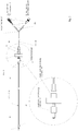
- Figure 1 shows schematically the system for breathing gas supply comprising a (not shown) breathing gas source 2, in a ventilator 1, a control unit 3, a pressure control module 4, a flow control module 6 and a memory 5, with a pressure sensor device 7 and a flow sensor device 8 and a user interface 9 for Specification of parameters 10 of the breathing gas supply or for the exchange of data are included.
- the system has a breathing gas hose 11 (the one line for inspiration and one line for expiration) and a patient interface 12.
- the ventilator 1 has at least one hose connection 10 to which the breathing gas hose 11 can be adapted.
- the ventilator also has a display for showing breathing gas values or breathing gas curves.
- the system optionally additionally has a humidifier 13 and / or an oxygen source 14 and / or a nebulizer 15 and / or a heater 16.
- the patient interface 12 is, for example, a tube for the windpipe or for the esophagus or a urinary catheter or
- the control unit 3 is set up and designed to control the breathing gas source 2 using the pressure control module 4 or the flow control module 6 for specifying a breathing gas pressure and / or a breathing gas flow.
- the breathing gas is made available at the hose connection 10 and passed through the hose 11 to a patient.
- the control unit 3 is set up and designed to additionally activate the humidifier 13 or the nebulizer and the heater 16 for heating and humidifying the breathing gas at least temporarily.
- the control unit 3 can also activate an oxygen source 14 and / or a nebulizer 15 for conditioning the breathing gas.
- the breathing gas hose 11 and / or the humidifier 13 and / or the nebulizer 15 each have a heater 16.
- the breathing gas hose 11 and / or the humidifier 13 and / or the nebulizer 15 has a heater 16.
- the control unit is set up and designed to recognize breathing efforts from the pressure signal and / or from the flow signal of the pressure sensor device and / or the flow sensor device.
- the user interface 9 for specifying parameters of the breathing gas supply or for exchanging data is designed, for example, as a touchscreen. Alternatively or in addition, a display and input keys can also be provided. In addition, the user interface 9 has at least one interface (USB, Bluetooth, WLAN ...) for connecting to external devices or a network in order to exchange data. Preset parameters are stored in the memory and can be called up.
- the breathing gas source 2 is designed, for example, as an electric motor with a fan wheel or as a compressed gas source with valves.
- the system is designed and set up, for example, so that the control unit, taking into account the signals from the flow and / or pressure sensor device, activates an oxygen source for admixing oxygen, which is modulated as a function of the breathing phase.
- the idea is to control the addition of oxygen so that more oxygen is available to the patient in phases of inspiration than for expiration.
- the system is designed and set up, for example, so that a pulse oximeter 17 or a Co2 measuring device 18 can be adapted, which then communicates with the system and / or is supplied with energy by it.
- the user - or an automatic algorithm - can use the measured values of these devices to set the correct flow rate and the correct oxygen admixture.
- the control unit takes into account measured values of the pulse oximeter 17 and / or of the Co2 measuring device 18 when activating / controlling the oxygen source and / or when activating / controlling the flow control module 6.
- the user inputs a specification to the control unit 3 via the user interface to activate the pressure control module or the flow control module 6.
- the specification can also be stored in the memory and read out by the control unit.
- the control unit 3 automatically selects the module 4 or 6 on the basis of information stored in the memory and controls it by specifying the parameters (pressure values, flow values ).
- Fig. 1 also shows a ventilation tube 12 designed as an endotracheal tube with tracheal end 19, with a distal end 18 with tube connector 20 for connection to ventilation tubes 11 for a ventilation device 1 and a continuous lumen for the breathing gases.
- the inflatable cuff 21 - also called a balloon - is formed near the tracheal end 19; the supply line 23 to the balloon is not shown.
- the feed line 23 to the inflatable balloon is routed along the outside or inside of the tube or is integrated into the tube wall and equipped with a connector 22 at the end for connection 24 to the ventilator.
- a pressure hose 25 establishes the connection between the pressure connection 24 of the ventilator and the connector 22 of the supply line 23.
- the endotracheal tube 12 is shown inserted into a patient's windpipe (ending well in front of the main bronchi).
- a pressure sensor can, near the tracheal end 19, be fastened on the outside of the tube 12 or introduced and fixed in the tube wall.
- the inflatable balloon 21 made of a thin plastic film, for example made of a thermoplastic elastomer with a wall thickness of, for example, less than 0.2 mm, is attached to the tracheal tube.
- a supply line 23 for compressed gas leads into the interior of the balloon, with the aid of which the balloon 21 is inflated with a filling pressure.
- a channel is incorporated in the wall of the tube which exits in the area of the balloon 21 through the opening from the wall of the tube 12.
- the control unit 3 is also set up and designed to control the breathing gas source 2 using the pressure control module 4 in such a way that a compressed gas is fed via a line to the pressure connection 24 of the ventilator.
- a pressure sensor which can determine the pressure of the gas in the pressure connection 24, is assigned to each pressure connection 24.
- Each pressure connection 24 is also assigned, for example, a valve which is set up to enable or block a compressed gas flow to the pressure connection 24. The valve is preferably controlled or switched via the control unit 3.
- the compressed gas can be taken from the breathing gas source 2 or from a separate compressed gas source (hospital line).
- the ventilator can be expanded to include a module with a pressure sensor and pressure regulator integrated into the control unit 3, for example, which sets the desired pressure in the balloon, automatically readjusts and the balloon pressure (Pbal) B. digitized signal of the control of the ventilator continuously available.
- the balloon pressure (Pbal) is preferably varied according to the pressure of inspiration and expiration.
- the pressure sensor can be arranged adjacent to or in the pressure connection 24 of the ventilator. The balloon pressure (Pbal) of the tube is measured by means of the pressure sensor and the measured values are transmitted to the control unit 3.
- a gastric tube equipped with an inflatable balloon that can be pressurized with a filling pressure of up to 35 mbar is provided for insertion into the patient's esophagus, and the esophageal balloon pressure prevailing in the gastric tube balloon is continuous or intermittent detected, the fluctuations of the intrathoracic pressure transmitted to the balloon of the gastric tube being detected and evaluated and fed to the ventilator to control the breathing gas flow.
- the gastric tube which can be inserted into the esophagus, is brought to rest against the wall of the esophagus by inflating its esophageal balloon, and in its middle and (better) lower third, the pressure curve within the chest over the wall of the esophagus (transmural) onto the esophageal balloon the gastric tube transmits.
- the pressure transmitted transmurally is picked up by this balloon and used as a measured value and control signal.
- the system is characterized in that the control unit 3 is set up and designed to control the breathing gas source 2 using the pressure control module 4 or the flow control module 6 for specifying a breathing gas pressure and / or a breathing gas flow and the breathing gas is provided at the hose connector 10 and via the breathing gas hose 11 is directed to a patient, wherein the control unit 3 is set up and designed to additionally at least temporarily activate the humidifier 13 or the nebulizer and the heater 16 for heating and humidifying the breathing gas or an oxygen source 14 and additionally a pulse oximeter 17 or a Co2 measuring device 18 is adapted, which then communicates with the system and / or is supplied with energy by it and wherein the control unit 3 is set up and designed to provide the measured values of these devices 17 or 18 to the user at the interface and / or an automatic algorithm to provide the correct flow rate u nd to use the measured values of these devices 17 or 18 for the activation or control of the oxygen source 14 and / or for the activation or control of the breathing gas source.
- the pressure adapter 26 has a male Luer connection 27 which is arranged on a short hose section 25 and which is adapted for connection to a female Luer connection of a pressure hose.
- the pressure adapter 26 has a female receptacle 28 for the male pressure connection 24 of the ventilator.
- a check valve 29 is arranged, which is pretensioned by a spring 30 in a closed position 34.
- the valve body 31 of the check valve 29 can be moved into an open position through the pressure connection 24.
- the closed position 34 Figure 4a
- the sealing surface 32 of the valve body 31 lies against the seal 33 of the check valve 29 in a sealing manner.
- the compressed gas line 24l in the pressure connection 24 also serves to move the valve body 31 into an open position 35 ( Figure 4b ) to move.
- the valve body has a contact surface 31k, against which the (tip of the) compressed gas line 24l is pressed when the male pressure connection 24 is pushed into the female receptacle 28.
- the male pressure connection 24 then presses (by means of the compressed gas line 24l) the valve body 31 against the spring force into the open position 35, which enables a gas flow from the male pressure connection 24 into the pressure adapter 26 (or the pressure hose 25).
- the female receptacle 28 is preferably made of a soft or elastomeric material and has an inner lumen 28i which is adapted to the outer diameter 24b, c of the male pressure connection 24 of the ventilator so that the male pressure connection 24 can easily be inserted into the female receptacle 28 , however, when the male pressure connection 24 is further inserted into the female receptacle 28, it ensures a sealing and clamping connection between the two.
- the inner lumen 28i is therefore smaller than the maximum outer diameter 24c.
- the pressure adapter 26 can thus be placed on the pressure connection 24 and leads to a sealed flow connection of compressed gas from the pressure connection 24 into the pressure adapter 26.
- Fig. 3 shows:
- the male pressure connector 24 of the ventilator has a threaded part 24g with which it is screwed into the ventilator 1, a compressed gas line 24l in the inner lumen of the pressure connector and a male connector 24a which has at least one conical section 24k.
- the conical section 24k has a small outer diameter 24b at the end 24b which faces away from the ventilator.
- the small outer diameter 24b is used for the easy attachment of the female receptacle 28.
- the outer diameter of the conical section 24k increases and reaches a maximum outer diameter 24c.
- the soft or elastic female receptacle 28 is securely fixed in the area of the maximum outer diameter 24c.
- a pressure hose 25 establishes the connection between the pressure connection 24 of the ventilator and the connector 22 of the supply line 23.
- the hose has a (male) Luer-Lock connection 35 at one end and at least one pressure adapter 26 at the other end, which is placed on the pressure connection 24 (of the ventilator) and provides a sealed flow connection for pressurized gas from the pressure connection 24 in leads the tube and further into the balloon.
- the at least one pressure adapter 26 has a female receptacle 28 for the male pressure connection 24 of the ventilator with a check valve 29 which is pretensioned by a spring 30 in a closed position and whose valve body 31 can be moved into an open position through the pressure connection 24.
- the pressure hose 25 can have a Y-piece 37 from which two pressure adapters 26 branch off. Of these, one pressure adapter 26 then has a check valve 29 and the other pressure adapter 26 does not have a check valve.
- the section of the hose 25 with the pressure adapter 26 is connected to a filter 40 via a female Luer lock connector 38.
- the filter 40 has a male lock connection 39 for this purpose.
- the filter 40 also has a female Luer lock connector 41, to which a male Luer lock connector 42 of the further pressure hose 25 can be connected.
- the filter 40 preferably has a non-detachable, for example glued, male Luer lock connection 39 and a non-detachable, for example glued, female Luer lock connection 41.
- the further section of the pressure hose has a (male) Luer-Lock connection 42 on which it is connected to the filter and a further (male) Luer-Lock connection 43 for connection to the balloon 21.
- the Luer-Lock connection 43 is via a Hose nozzle 44 inextricably connected to hose 25.
Landscapes
- Health & Medical Sciences (AREA)
- Pulmonology (AREA)
- Heart & Thoracic Surgery (AREA)
- Engineering & Computer Science (AREA)
- Anesthesiology (AREA)
- Biomedical Technology (AREA)
- Emergency Medicine (AREA)
- Hematology (AREA)
- Life Sciences & Earth Sciences (AREA)
- Animal Behavior & Ethology (AREA)
- General Health & Medical Sciences (AREA)
- Public Health (AREA)
- Veterinary Medicine (AREA)
- Measurement Of The Respiration, Hearing Ability, Form, And Blood Characteristics Of Living Organisms (AREA)
- External Artificial Organs (AREA)
Abstract
Description
- Die ventilatorassoziierte Pneumonie (VAP) ist die häufigste nosokomiale Infektion bei Beatmungspatienten auf der Intensivstation. Vielfach wird diese durch Erreger aus dem oberen Respirationstrakt verursacht, welche aufgrund von Mikroaspirationen am Tubus-Ballon vorbei in die Lunge gelangen. Die ventilatorassoziierte Pneumonie erhöht die Sterblichkeitsrate zusätzlich um ca. 10%, verlängert die Beatmungsdauer und verursacht zusätzliche Kosten.
- Als eine Maßnahme innerhalb eines Maßnahmenbündels zur Reduzierung des VAP-Risikos gilt die kontinuierliche Überwachung und Steuerung des geblockten Ballons des Endotrachealtubus bzw. der Trachealkanüle. Die auf Intensivstationen angewendete intermittierende Ballon-Kontrolle mithilfe eines Manometers ist weit verbreitet. Damit sollen Komplikationen im Zusammenhang mit einem zu niedrigen oder zu hohen Ballondruck vermieden werden. Obwohl durch diese Methode theoretisch eine Verringerung der Komplikationen erreicht werden könnte, ist sie zur dauerhaften Aufrechterhaltung und kontinuierlichen Überwachung einer adäquaten Tubusblockierung unzureichend geeignet. Die wichtigste Funktion des Trachealtubus-Ballons besteht darin, den extraluminalen Atemweg gegen Luft und eine Flüssigkeitsleckage zu verschließen, damit eine wirksame maschinelle Beatmung mit positivem Druck möglich ist, und um eine Mikroaspiration von kontaminiertem subglottischem Sekret zu vermeiden. Ein zu geringer Druck im Ballon sorgt für eine Mikroaspiration. Ein zu hoher Druck für Läsionen.
- Die erfindungsgemäße Aufgabe ist es ein verbessertes und sicheres System zur Atemgasversorgung mit einem Trachealtubus-Ballon anzugeben.
- Die Aufgabe wird gelöst durch ein System zur Atemgasversorgung umfassend ein Beatmungsgerät eine Atemgasquelle , eine Steuereinheit , ein Drucksteuermodul und/oder ein Flusssteuermodul und einen Speicher, wobei ebenfalls eine Drucksensoreinrichtung und eine Flusssensoreinrichtung und eine Anwenderschnittstelle zur Vorgabe von Parametern der Atemgasversorgung oder zum Austausch von Daten umfasst sind, wobei das Beatmungsgerät zumindest einen Schlauchanschluss aufweist, an den der Atemgasschlauch adaptiert werden kann und ein Patienteninterface als Schnittstelle zum Patienten und zumindest einen Druckanschluss für einen zusätzlichen Druckschlauch dadurch gekennzeichnet, dass als Patienteninterface ein Tubus verwendet ist, der einen Ballon aufweist, der über den Druckanschluss und den daran adaptierten Druckschlauch definiert mit Druckgas befüllbar ist. Das erfindungsgemäße System ist auch dadurch gekennzeichnet, dass das Patienteninterface als ein Tubus für die Luftröhre oder für die Speiseröhre oder als ein Blasenkatheter ausgebildet ist.
Das erfindungsgemäße System ist alternativ dadurch gekennzeichnet, dass die Steuereinheit eingerichtet und ausgebildet ist die Atemgasquelle, unter Verwendung des Drucksteuermoduls oder des Flusssteuermoduls, zur Vorgabe eines Atemgasdruckes und/oder eines Atemgasflusses anzusteuern und das Atemgas am Schlauchanschluss bereitgestellt und über den Atemgasschlauch zu einem Patienten geleitet wird.
Das erfindungsgemäße System ist ergänzend dadurch gekennzeichnet, dass die Steuereinheit eingerichtet und ausgebildet ist zusätzlich zumindest zeitweise den Anfeuchter oder den Vernebler und die Heizung zur Erwärmung und Anfeuchtung des Atemgases oder eine Sauerstoffquelle zu aktivieren.
Das erfindungsgemäße System ist auch dadurch gekennzeichnet, dass zusätzlich ein Pulsoximeter oder ein Co -Messgerät adaptiert ist, welches dann mit dem System kommuniziert und/oder von ihm mit Energie versorgt wird und wobei die Steuereinheit eingerichtet und ausgebildet ist die Messwerte dieser Geräte oder dem Anwender an der Schnittstelle bereitzustellen und/oder ein automatischer Algorithmus die richtige Flussrate und die Messwerte dieser Geräte oder für die Aktivierung oder Steuerung der Sauerstoffquelle und/oder bei der Aktivierung oder Steuerung der Atemgasquelle zu nutzen.
Das erfindungsgemäße System ist alternativ auch dadurch gekennzeichnet, dass das Patienteninterface als Endotrachealtubus mit trachealem Ende und mit einem distalen Ende, mit Tubuskonnektor zum Anschluss an den Atemgasschlauch und einem durchgehenden Lumen für die Atemgase ausgeführt ist, wobei nahe am trachealen Ende der aufblasbare Ballon ausgebildet ist, wobei der Ballon über eine Zuführleitung , die über den Druckschlauch mit dem Druckanschluss des Beatmungsgerätes verbunden ist, mit Druckgas aus der Atemgasquelle oder einer Druckgasquelle befüllbar ist. - Das erfindungsgemäße System ist ergänzend auch dadurch gekennzeichnet, dass die Steuereinheit auch eingerichtet und ausgebildet ist die Atemgasquelle , unter Verwendung des Drucksteuermoduls so anzusteuern, dass ein Druckgas über eine Leitung zum Druckanschluss des Beatmungsgerätes geführt wird, wobei zumindest ein Druckanschluss vorhanden, und jedem Druckanschluss ein Drucksensor zugeordnet ist, der den Druck des Gases in dem Druckanschluss bestimmen kann und/oder jedem Druckanschluss auch ein Ventil zugeordnet ist, welches eingerichtet ist, eine Druckgasströmung zu dem Druckanschluss freizugeben oder zu sperren.
Das erfindungsgemäße System ist optional auch dadurch gekennzeichnet, dass ein Anwender über die Schnittstelle den Ballondruck festlegen kann und die Steuereinheit über den Drucksensor und den Druckregler den gewünschten Druck im Ballon einstellt, selbsttätig nachregelt und den Ballondruck (Pbal) als Signal der Steuerung des Beatmungsgerätes zur Verfügung stellt, wobei der Ballondruck (Pbal) beispielsweise entsprechend dem Druck der Inspiration und Exspiration variiert wird.
Das erfindungsgemäße System ist beispielsweise auch dadurch gekennzeichnet, dass der Druckanschluss des Beatmungsgerätes ein Verbindungsmittel aufweist, zur lösbaren Verbindung mit dem Beatmungsgerät, und ein inneres Lumen und eine Druckgasleitung im inneren Lumen, sowie einen männlichen Anschluss a, der zumindest einen konischen Abschnitt aufweist, der zur lösbaren Verbindung mit der weiblichen Aufnahme des Druckadapters ausgebildet ist.
Das erfindungsgemäße System ist ergänzend auch dadurch gekennzeichnet, dass ein Druckadapter umfasst ist, welcher einen männlichen Luer-Anschluß aufweist, der an einem kurzen Schlauchabschnitt angeordnet ist, und der eine weibliche Aufnahme für den männlichen Druckanschluss des Beatmungsgerätes aufweist, wobei ein Rückschlagventil in dem Druckadapter angeordnet ist, das in einer Schließstellung vorgespannt ist und dessen Ventilkörper durch den Druckanschluss in eine Öffnungsstellung bewegt werden kann.
Das erfindungsgemäße System ist alternativ auch dadurch gekennzeichnet, dass ein Druckschlauch umfasst ist, der an einem Ende einen Luer-Lock Anschluss aufweist und an dem anderen Ende zumindest einen Druckadapter aufweist, der auf den Druckanschluss des Beatmungsgerätes gesteckt werden kann, wobei ein Rückschlagventil in dem Druckadapter angeordnet ist, das in einer Schließstellung vorgespannt ist und dessen Ventilkörper, bei der Verbindung mit dem Druckanschluss, durch den Druckanschluss in eine Öffnungsstellung bewegt wird.
Das erfindungsgemäße System ist auch dadurch gekennzeichnet, dass der Druckadapter einen männlichen Luer-Anschluß aufweist, der an einem Schlauchabschnitt angeordnet ist, und der zur Verbindung mit einem weiblichen Luer-Anschluss eines Druckschlauches angepasst ist, wobei der Druckadapter zudem eine weibliche Aufnahme für den männlichen Druckanschluss des Beatmungsgerätes aufweist.
Das erfindungsgemäße System ist zudem dadurch gekennzeichnet, dass im Bereich der weiblichen Aufnahme ein Rückschlagventil angeordnet ist, welches durch eine Feder in einer Schließstellung vorgespannt ist, wobei der Ventilkörper des Rückschlagventils durch den Druckanschluss in eine Öffnungsstellung bewegbar ist.
Das erfindungsgemäße System ist auch dadurch gekennzeichnet, dass der Druckanschluss eine Druckgasleitung I aufweist die Druckgas leitet und auch dazu dient, den Ventilkörper in eine Öffnungsstellung zu bewegen, wenn der Druckadapter mit dem Druckanschluss verbunden wird.
Das erfindungsgemäße System ist alternativ dadurch gekennzeichnet, dass der Ventilkörper eine Kontaktfläche aufweist, gegen die die (Spitze der) Druckgasleitung gedrängt wird, wenn der männliche Druckanschluss in die weibliche Aufnahme geschoben wird.
Der männliche Druckanschluss drückt dann (mittels der Druckgasleitung I) den Ventilkörper gegen die Federkraft in die Offenstellung, die einen Gasfluss aus dem männlichen Druckanschluss in den Druckadpter (oder den Druckschlauch) ermöglicht.
Das erfindungsgemäße System ist beispielsweise dadurch gekennzeichnet, dass die weibliche Aufnahme aus einem weichen oder elastomeren Material gefertigt ist und ein Innenlumen aufweist, welches dem Außendurchmesser des männlichen Druckanschlusses des Beatmungsgerätes so angepasst ist, dass der männliche Druckanschluss in die weibliche Aufnahme eingeführt werden kann und eine dichtende und klemmende Verbindung zwischen beiden sicherstellt ist.
Der Druckadapter kann so auf den Druckanschluss gesetzt werden und führt zu einer abgedichteten Strömungsverbindung von Druckgas aus dem Druckanschluss in den Druckadapter. - Das erfindungsgemäße System ist alternativ dadurch gekennzeichnet, dass der Druck des Ballons dynamisch an die jeweilige Drucksituation in der Inspiration angepasst wird. Gerade bei Patienten mit hohen Beatmungsdrücken kann hierdurch sowohl eine adäquate Blockung im Endotrachealtubus bzw. in der Trachealkanüle in der Inspiration sichergestellt werden, Das erfindungsgemäße System ist auch dadurch gekennzeichnet, dass der Druck des Ballons dynamisch an die jeweilige Drucksituation in der Exspiration angepasst wird. als auch die notwendige Entlastung für die Durchblutung der Trachealschleimhaut in der Exspirationsphase gewährleistet werden.
Das erfindungsgemäße System ist alternativ auch dadurch gekennzeichnet, dass die Steuereinheit auch eingerichtet und ausgebildet ist die Atemgasquelle , unter Verwendung des Drucksteuermoduls so anzusteuern, dass Druckgas über eine Leitung zum Druckanschluss des Beatmungsgerätes geführt wird, wobei dem Druckanschluss ein Drucksensor zugeordnet ist, der den Druck des Gases in dem Druckanschluss bestimmt, wobei der Druck des Gases in dem Druckanschluss dem Druck im Ballon (Pbal) im Wesentlichen entspricht, wenn eine Druckgasleitende Verbindung zwischen dem Ballon und dem Druckgasanschluss hergestellt ist.
Das erfindungsgemäße System ist ergänzend dadurch gekennzeichnet, dass die Steuereinheit einen Druckregler aufweist oder diesen ansteuert, um den gewünschten Druck im Ballon einzustellen und den Ballondruck (Pbal) als beispielsweise digitalisiertes Signal der Steuereinheit zur Verfügung stellt.
Das erfindungsgemäße System ist alternativ auch dadurch gekennzeichnet, dass die Steuereinheit den Ballondruck (Pbal) entsprechend dem Druck der Inspiration und der Exspiration variiert.
Das erfindungsgemäße System ist auch dadurch gekennzeichnet, dass der gemessene Ballondruck als zusätzliche Druckkurve auf dem Beatmungsgerät angezeigt wird.
Die Aufgabe wird auch gelöst durch ein Beatmungsgerät eingerichtet und ausgebildet zur Verwendung in einem erfindungsgemäßen System.
Die Aufgabe wird auch gelöst durch einen Druckadapter eingerichtet und ausgebildet zur Verwendung in einem erfindungsgemäßen System. Der Druckadapter weist einen männlichen Luer-Anschluß aufweist, der an einem kurzen Schlauchabschnitt angeordnet ist, und der eine weibliche Aufnahme für den männlichen Druckanschluss des Beatmungsgerätes aufweist, wobei ein Rückschlagventil in dem Druckadapter angeordnet ist, welches in einer Schließstellung vorgespannt ist und dessen Ventilkörper durch den Druckanschluss in eine Öffnungsstellung bewegt werden kann.
Die Aufgabe wird auch gelöst durch einen Druckschlauch eingerichtet und ausgebildet zur Verwendung in einem erfindungsgemäßen System. Der Druckschlauch weist an einem Ende einen Luer-Lock Anschluss auf und an dem anderen Ende zumindest einen Druckadapter auf, der auf den Druckanschluss gesetzt werden kann, wobei ein Rückschlagventil in dem Druckadapter angeordnet ist, welches in einer Schließstellung vorgespannt ist und dessen Ventilkörper durch den Druckanschluss in eine Öffnungsstellung bewegt werden kann.
Die Aufgabe wird auch gelöst durch einen Druckschlauch 25 mit einem Druckadapter 26 eingerichtet und ausgebildet zur Verwendung in einem System nach zumindest einem der vorhergehenden Ansprüche.
Für den Ballondruck sollte in etwa ein Wert von 25 cm H2O aufrechterhalten werden, da die Mikroaspiration bei einem Wert von unter 20 cm H2O auftritt und das Risiko von ischämischen Läsionen der Trachea aufgrund der Minderdurchblutung der Trachealschleimhaut bei einem Druck von über 30 cmH2O eine größere Rolle spielt. - Die Erfindung bietet folgende Vorteile:
- Aufrechterhaltung und Überwachung eines durch den Anwender vorgegebenen Ballondrucks
- Zwei Betriebsarten: Gleichbleibende Regelung des Ballons (statisch) oder automatische Anpassung an den Plateaudruck
- Erkennung von defekten Ballonmanschetten (Alarm) und Leckagen
- Algorithmus zur Hustenerkennung (Ballonanpassung)
- Modus zur zeitweiligen Überblockung des Ballons (z.B. bei Mundpflege, subglottischen Spülungen, Bauchlagerung, ...)
- Modus für die Leerung des Ballons (Extubation)
- Überwachung von Druckwerten des Ballons (PBallon), Zielwerte = 20-30 cmH2O
- da zu geringer Ballondruck < 20 cmH2O -> Mikroaspiration
- da dauerhaft zu hoher Ballondruck > 30 cmH2O -> Ischämie der Trachealschleimhaut
- Die Funktionsweise des Ballons kann an die unterschiedlichen Bedürfnisse angepasst werden. Zur Überwachung und Optimierung des Ballons stehen zwei Ballon-Modi zur Verfügung. Die Verfügbarkeit der Ballon-Modi und die Regelung des automatischen Ballon-Modus können auf der Konfigurationsebene des Beatmungsgerätes (gemäß den Abteilungsvorgaben) eingestellt werden
Mit dem "statischen" Ballon-Modus gibt der Anwender einen definierten Ballondruck (PBallon konstant) vor, welcher kontinuierlich überwacht und optimiert wird.
Der kontinuierlich gemessene Ballondruck wird als zusätzliche Druckkurve angezeigt und kann mit entsprechenden Alarmen für Leckage, defekte Tubusblockmanschette und Drucküberwachung versehen werden.
Im "automatischen" Modus adaptiert sich die Blockung des Ballons an die jeweilige Drucksituation in der Inspiration. Gerade bei Patienten mit hohen Beatmungsdrücken kann hierdurch sowohl eine adäquate Blockung im Endotrachealtubus bzw. in der Trachealkanüle in der Inspiration sichergestellt werden, als auch die notwendige Entlastung für die Durchblutung der Trachealschleimhaut in der Exspirationsphase gewährleistet werden.
Der kontinuierlich gemessene Ballondruck wird auch hier als zusätzliche Druckkurve angezeigt und kann mit entsprechenden Alarmen versehen werden.
Eine automatische Hustenüberwachung kann kritische Situationen erkennen, welche ein angepasstes Druckniveau im Tubus erfordern. In dieser Situation wird in beiden Ballon-Modi ein erhöhtes Druckniveau (PBallon max) aufgebaut.
Über eine Taste der Schnittstelle kann der Anwender eine zeitweilige Überblockung des Ballons (z.B. bei Mundpflege, subglottischen Spülungen, Bauchlagerung, ...) mit einstellbarer Zeitvorgabe auslösen.
Das Manöver sowie die verbleibende Restzeit wird in der Informationszeile des Intensivventilators entsprechend angezeigt.
Auf Tastendruck kann der Ballonscout den Ballon entblocken und so die sichere Extubation erleichtern. -
Figur 1 zeigt schematisch das System zur Atemgasversorgung umfassend eine (nicht gezeigte) Atemgasquelle 2, in einem Beatmungsgerät 1, eine Steuereinheit 3, ein Drucksteuermodul 4, ein Flusssteuermodul 6 und einen Speicher 5, wobei ebenfalls eine Drucksensoreinrichtung 7 und eine Flusssensoreinrichtung 8 und eine Anwenderschnittstelle 9 zur Vorgabe von Parametern 10 der Atemgasversorgung oder zum Austausch von Daten umfasst sind. Das System weist einen Atemgasschlauch 11 (der eine Leitung für die Inspiration und eine Leitung für die Exspiration umfassen kann) und ein Patienteninterface 12 auf. Das Beatmungsgerät 1 weist zumindest einen Schlauchanschluss 10 auf, an den der Atemgasschlauch 11 adaptiert werden kann. Das Beatmungsgerät weist auch eine Anzeige auf, zur Darstellung von Atemgaswerten oder von Atemgaskurven. Das System weist optional zusätzlich einen Anfeuchter 13 und/oder eine Sauerstoffquelle 14 und/oder einen Vernebler 15 und/oder eine Heizung 16 auf. Das Patienteninterface 12 ist beispielsweise ein Tubus für die Luftröhre oder für die Speiseröhre oder ein Blasenkatheter oder - Die Steuereinheit 3 ist eingerichtet und ausgebildet die Atemgasquelle 2, unter Verwendung des Drucksteuermoduls 4 oder des Flusssteuermoduls 6, zur Vorgabe eines Atemgasdruckes und/oder eines Atemgasflusses anzusteuern. Das Atemgas wird am Schlauchanschluss 10 bereitgestellt und über den Schlauch 11 zu einem Patienten geleitet.
Die Steuereinheit 3 ist eingerichtet und ausgebildet zusätzlich zumindest zeitweise den Anfeuchter 13 oder den Vernebler und die Heizung 16 zur Erwärmung und Anfeuchtung des Atemgases zu aktivieren.
Die Steuereinheit 3 kann zusätzlich eine Sauerstoffquelle 14 und/oder einen Vernebler 15 zur Konditionierung des Atemgases aktivieren.
Der Atemgasschlauch 11 und/oder der Anfeuchter 13 und/oder der Vernebler 15 weisen jeweils eine Heizung 16 auf. Alternativ weist zumindest der Atemgasschlauch 11 und/oder der Anfeuchter 13 und/oder der Vernebler 15 eine Heizung 16 auf.
Die Steuereinheit ist zur Erkennung von Atmungsbemühungen aus dem Drucksignal und/oder aus dem Flusssignal der Drucksensoreinrichtung und/oder der Flusssensoreinrichtung eingerichtet und ausgebildet.
Die Anwenderschnittstelle 9 zur Vorgabe von Parametern der Atemgasversorgung oder zum Austausch von Daten ist beispielsweise ausgebildet als ein Touchscreen. Alternativ oder ergänzend können auch ein Display und Eingabetasten vorgesehen sein. Ergänzend weist die Anwenderschnittstelle 9 zumindest eine Schnittstelle (USB, Bluetooth, WLAN...) zur Verbindung mit externen Geräten oder einem Netzwerk auf, um Daten auszutauschen. Vorgegebene Parameter werden im Speicher abrufbar abgelegt.
Die Atemgasquelle 2 ist beispielsweise ausgebildet als Elektromotor mit Lüfterrad oder als Druckgasquelle mit Ventilen. - Das System ist beispielsweise ausgebildet und eingerichtet, dass die Steuereinheit unter Berücksichtigung der Signale der Fluss- und/oder Drucksensoreinrichtung, eine Sauerstoffquelle zur Sauerstoffbeimischung aktiviert, die Atemphasenabhängig moduliert wird. Beispielsweise ist daran gedacht die Sauerstoffbeimischung so zu steuern, dass in Phasen der Inspiration dem Patienten mehr Sauerstoff zur Verfügung steht als zur Exspiration.
- Das System ist beispielsweise ausgebildet und eingerichtet, dass ein Pulsoximeter 17 oder ein Co2-Messgerät 18 adaptiert werden kann, welches dann mit dem System kommuniziert und/oder von ihm mit Energie versorgt wird. Über die Messwerte dieser Geräte kann der Anwender - oder ein automatischer Algorithmus - die richtige Flussrate und die richtige Sauerstoff-Beimischung einstellen. Beispielsweise berücksichtigt die Steuereinheit Messwerte des Pulsoximeters 17 und/oder des Co2-Messgerätes 18 bei der Aktivierung / Steuerung der Sauerstoffquelle und/oder bei der Aktivierung / Steuerung des Flusssteuermoduls 6.
- Erfindungsgemäß ist daran gedacht, dass der Anwender über die Anwenderschnittstelle eine Vorgabe an die Steuereinheit 3 eingibt das Drucksteuermodul oder das Flusssteuermodul 6 zu aktivieren. Die Vorgabe kann auch im Speicher abgelegt sein und von der Steuereinheit ausgelesen werden. Erfindungsgemäß ist auch daran gedacht, dass die Steuereinheit 3 selbststätig anhand im Speicher abgelegter Informationen das Modul 4 oder 6 wählt und unter Vorgabe der Parameter (Druckwerte, Flusswerte ...) ansteuert.
-
Fig. 1 zeigt auch einen Beatmungstubus 12 in der Ausführung als Endotrachealtubus mit trachealen Ende 19, mit einem distalem Ende 18 mit Tubuskonnektor 20 zum Anschluss an Beatmungsschläuche 11 für ein Beatmungsgerät 1 und einem durchgehenden Lumen für die Atemgase. Nahe am trachealen Ende 19 ist die aufblasbare Manschette 21 - auch Ballon genannt - ausgebildet, die Zuführleitung 23 zum Ballon ist nicht dargestellt.
Die Zuführleitung 23 zu dem aufblasbaren Ballon ist aussenseitig oder innenseitig am Tubus entlanggeführt oder in die Tubuswand integriert und mit einem Anschlussstecker 22 am Ende zum Anschluss 24 an das Beatmungsgerät ausgerüstet. Ein Druckschlauch 25 stellt die Verbindung her zwischen dem Druckanschluss 24 des Beatmungsgerätes und dem Anschlussstecker 22 der Zuführleitung 23. - Der Endotrachealtubus 12 ist eingeführt in die Luftröhre eines Patienten dargestellt (endend deutlich vor den Hauptbronchien).
Ein Drucksensor kann, nahe dem trachealen Ende 19, außenseitig an dem Tubus 12 befestigt bzw. in die Tubus-Wandung eingebracht und fixiert sein.
Außenseitig nahe dem trachealen Ende 19 des Tubus ist der aufblasbare Ballon 21 aus einer dünnen Kunststofffolie beispielsweise aus einem thermoplastischen Elastomer mit einer Wanddicke von beispielsweise kleiner 0,2 mm auf dem Trachealtubus befestigt.
In das Innere des Ballons führt eine Zufuhrleitung 23 für Druckgas, mit deren Hilfe der Ballon 21 mit einem Fülldruck aufgeblasen wird. Für die Zufuhr der Druckgas zu dem Ballon 21 ist beispielsweise in der Wandung des Tubus ein Kanal eingearbeitet, der im Bereich des Ballons 21 durch die Öffnung aus der Wandung des Tubus 12 austritt. - Die Steuereinheit 3 ist auch eingerichtet und ausgebildet die Atemgasquelle 2, unter Verwendung des Drucksteuermoduls 4 so anzusteuern, dass ein Druckgas über eine Leitung zum Druckanschluss 24 des Beatmungsgerätes geführt wird. Erfindungsgemäß ist zumindest ein Druckanschluss 24 vorhanden, bevorzugt zumindest zwei. Jedem Druckanschluss 24 ist ein Drucksensor zugeordnet, der den Druck des Gases in dem Druckanschluss 24 bestimmen kann. Jedem Druckanschluss 24 ist beispielsweise auch ein Ventil zugeordnet, welches eingerichtet ist, eine Druckgasströmung zu dem Druckanschluss 24 freizugeben oder zu sperren. Das Ventil wird bevorzugt über die Steuereinheit 3 gesteuert bzw. geschaltet. Das Druckgas kann der Atemgasquelle 2 entnommen werden oder einer separaten Druckgasquelle (Krankenhausleitung).
- Zur Registrierung des Ballondrucks (Pbal) kann das Beatmungsgerät um ein beispielsweise in die Steuereinheit 3 integriertes Modul mit Drucksensor und Druckregler erweitert sein, welches den gewünschten Druck im Ballon einstellt, selbsttätig nachregelt und den Ballondruck (Pbal) als z. B. digitalisiertes Signal der Steuerung des Beatmungsgerätes kontinuierlich zur Verfügung stellt. Bevorzugt wird der Ballondruck (Pbal) entsprechend dem Druck der Inspiration und Exspiration variiert. Der Drucksensor kann benachbart zu oder im Druckanschluss 24 des Beatmungsgerätes angeordnet sein. Der Ballondruck (Pbal) des Tubus wird mittels des Drucksensors gemessen und die Meßwerte der Steuereinheit 3 übermittelt. Gemäß einem weiteren Vorschlag der Erfindung wird zur Optimierung der Steuerung des Beatmungsgerätes eine mit einem aufblasbaren und mit einem Fülldruck von bis zu 35 mbar beaufschlagbaren Ballon ausgerüstete Magensonde zum Einführen in die Speiseröhre des Patienten vorgesehen und der im Ballon der Magensonde herrschende ösophageale Ballondruck kontinuierlich oder intermittierend erfaßt, wobei die sich auf den Ballon der Magensonde übertragenden Schwankungen des intrathorakalen Drucks erfasst und ausgewertet werden und dem Beatmungsgerät zur Steuerung des Atemgasflusses zugeführt werden. Die in die Speiseröhre einführbare Magensonde wird durch Aufblasen ihres ösophagealen Ballons zum Anliegen an die Wandung der Speiseröhre gebracht, die in ihrem mittleren und (besser) unteren Drittel den Druckverlauf innerhalb des Brustkorbs über die Wand der Speiseröhre hinweg (transmural) auf den ösophageal platzierten Ballon der Magensonde überträgt. Der transmural übertragene Druck wird von diesem Ballon aufgenommen und als Messwert und Steuerungssignal nutzbar gemacht.
- Das System ist dadurch gekennzeichnet, dass die Steuereinheit 3 eingerichtet und ausgebildet ist die Atemgasquelle 2, unter Verwendung des Drucksteuermoduls 4 oder des Flusssteuermoduls 6, zur Vorgabe eines Atemgasdruckes und/oder eines Atemgasflusses anzusteuern und das Atemgas am Schlauchanschluss 10 bereitgestellt und über den Atemgasschlauch 11 zu einem Patienten geleitet wird, wobei die Steuereinheit 3 eingerichtet und ausgebildet ist zusätzlich zumindest zeitweise den Anfeuchter 13 oder den Vernebler und die Heizung 16 zur Erwärmung und Anfeuchtung des Atemgases oder eine Sauerstoffquelle 14 zu aktivieren und wobei zusätzlich ein Pulsoximeter 17 oder ein Co2-Messgerät 18 adaptiert ist, welches dann mit dem System kommuniziert und/oder von ihm mit Energie versorgt wird und wobei die Steuereinheit 3 eingerichtet und ausgebildet ist die Messwerte dieser Geräte 17 oder 18 dem Anwender an der Schnittstelle bereitzustellen und/oder ein automatischer Algorithmus die richtige Flussrate und die Messwerte dieser Geräte 17 oder 18 für die Aktivierung oder Steuerung der Sauerstoffquelle 14 und/oder bei der Aktivierung oder Steuerung der Atemgasquelle zu nutzen.
-
Fig. 2 und4 zeigen:
Der Druckadapter 26 weist einen männlichen Luer-Anschluß 27 auf, der an einem kurzen Schlauchabschnitt 25 angeordnet ist, und der zur Verbindung mit einem weiblichen Luer-Anschluss eines Druckschlauches angepasst ist.
Zusätzlich weist der Druckadapter 26 eine weibliche Aufnahme 28 für den männlichen Druckanschluss 24 des Beatmungsgerätes auf. Im Bereich der weibliche Aufnahme 28 ist ein Rückschlagventil 29 angeordnet, welches durch eine Feder 30 in einer Schließstellung 34 vorgespannt ist. Der Ventilkörper 31 des Rückschlagventils 29 kann durch den Druckanschluss 24 in eine Öffnungsstellung bewegt werden kann.
In der Schließstellung 34 (Fig. 4a ) liegt die Dichtfläche 32 des Ventilkörpers 31 dichtend an der Dichtung 33 des Rückschlagventils 29 an. - Die Druckgasleitung 24l in dem Druckanschluss 24 dient auch dazu, den Ventilkörper 31 in eine Öffnungsstellung 35 (
Fig. 4b ) zu bewegen.
Dazu weist der Ventilkörper eine Kontaktfläche 31k auf, gegen die die (Spitze der) Druckgasleitung 24l gedrängt wird, wenn der männlichen Druckanschluss 24 in die weibliche Aufnahme 28 geschoben wird. Der männlichen Druckanschluss 24 drückt dann (mittels der Druckgasleitung 24l) den Ventilkörper 31 gegen die Federkraft in die Offenstellung 35, die einen Gasfluss aus dem männlichen Druckanschluss 24 in den Druckadpter 26 (oder den Druckschlauch 25) ermöglicht.
Die weibliche Aufnahme 28 ist bevorzugt aus einem weichen oder elastomeren Material gefertigt und weist ein Innenlumen 28i auf, welches dem Außendurchmesser 24b, c des männlichen Druckanschlusses 24 des Beatmungsgerätes so angepasst ist, dass der männlichen Druckanschluss 24 leicht in die weibliche Aufnahme 28 eingeführt werden kann, dann jedoch, wenn der männlichen Druckanschluss 24 weiter in die weibliche Aufnahme 28 eingeführt ist, eine dichtende und klemmende Verbindung zwischen beiden sicherstellt. Das Innenlumen 28i ist also kleiner als der maximale Außendurchmesser 24c.
Der Druckadapter 26 kann so auf den Druckanschluss 24 gesetzt werden und führt zu einer abgedichteten Strömungsverbindung von Druckgas aus dem Druckanschluss 24 in den Druckadapter 26. - Der neue Druckadapter 26 erlaubt somit (mittelbar über Verbindungsschläuche):
- den Anschluss eines Ösophaguskatheters an das Beatmungsgerät für ein transpulmonales Druckmonitoring und eine gastrale Druckmessung.
- den Anschluss eines Blasenkatheters an das Beatmungsgerät zur Erfassung und Überwachung des intraabdominelles Drucks.
-
Fig. 3 zeigt:
Der männliche Druckanschluss 24 des Beatmungsgerätes weist einen Gewindeteil 24g auf, mit dem er in das Beatmungsgerät 1 geschraubt wird, eine Druckgasleitung 24l im inneren Lumen des Druckanschlusses und einen männlichen Anschluss 24a, der zumindest einen konischen Abschnitt 24k aufweist. Der konische Abschnitt 24k weist einen geringen Außendurchmesser 24b an dem Ende 24b auf, welches dem Beatmungsgerät abgewandt ist. Der geringe Außendurchmesser 24b dient dem leichten Aufsetzen der weiblichen Aufnahme 28. Dem Beatmungsgerät weiter zugewandt nimmt der Außendurchmesser des konischen Abschnitts 24k zu und erreicht einen maximalen Außendurchmesser 24c. Im Bereich des maximalen Außendurchmessers 24c ist die weiche oder elastische weibliche Aufnahme 28 sicher fixiert. -
Fig. 5 zeigt:
Ein Druckschlauch 25 stellt die Verbindung her zwischen dem Druckanschluss 24 des Beatmungsgerätes und dem Anschlussstecker 22 der Zuführleitung 23.
Dazu weist der Schlauch an einem Ende einen (männlichen) Luer-Lock Anschluss 35 auf und an dem anderen Ende zumindest einen Druckadapter 26, der auf den Druckanschluss 24 (des Beatmungsgerätes) gesetzt werden und zu einer abgedichteten Strömungsverbindung von Druckgas aus dem Druckanschluss 24 in den Schlauch und weiter in den Ballon führt.
Der zumindest eine Druckadapter 26 weist eine weibliche Aufnahme 28 für den männlichen Druckanschluss 24 des Beatmungsgerätes mit einem Rückschlagventil 29 auf, das durch eine Feder 30 in einer Schließstellung vorgespannt ist und dessen Ventilkörper 31 durch den Druckanschluss 24 in eine Öffnungsstellung bewegt werden kann. - Der Druckschlauch 25 kann ein Y-Stück 37 aufweisen, von dem zwei Druckadapter 26 abzweigen. Davon weist dann ein Druckadapter 26 ein Rückschlagventil 29 auf und der andere Druckadapter 26 weist kein Rückschlagventil auf.
Der Abschnitt des Schlauches 25 mit dem Druckadapter 26 ist über einen weiblichen Luer-Lock Anschluss 38 mit einem Filter 40 verbunden. Der Filter 40 weist dazu einen männlichen Lock Anschluss 39 auf. Der Filter 40 weist zudem einen weiblichen Luer Lock Anschluss 41 auf, an den ein männlicher Luer Lock Anschluss 42 des weiteren Druckschlauches 25 konnektiert werden kann.
Der Filter 40 weist bevorzugt einen unlösbaren, beispielsweise verklebten, männlichen Luer-Lock Anschluss 39 und einen unlösbaren, beispielsweise verklebten, weiblichen Luer-Lock Anschluss 41 auf.
Der weitere Abschnitt des Druckschlauches weist dazu einen (männlichen) Luer-Lock Anschluss 42 auf der mit dem Filter verbunden wird und einen weiteren (männlichen) Luer-Lock Anschluss 43 zur Verbindung mit dem Ballon 21. Der Luer-Lock Anschluss 43 ist über eine Schlauchtülle 44 unlösbar mit dem Schlauch 25 verbunden. - Der Druckschlauch hat folgende Einsatzmöglichkeiten:
- druckgeprüfte Sicherheitsleitung zur Verbindung zwischen Beatmungsgerät und Endotrachealtubus bzw. Trachealkanülen zur Ballonregulierung und - überwachung
- verhindert die versehentliche Entlastung des Ballons bei Dekonnektion
- erlaubt die Erfassung von Leckagen vor Aktivierung der Ballonfunktion (Prüfadapter)
Claims (16)
- System zur Atemgasversorgung umfassend ein Beatmungsgerät 1 eine Atemgasquelle 2, eine Steuereinheit 3, ein Drucksteuermodul 4 und einen Speicher 5, wobei ebenfalls eine Drucksensoreinrichtung 7 und eine Flusssensoreinrichtung 8 und eine Anwenderschnittstelle 9 zur Vorgabe von Parametern der Atemgasversorgung oder zum Austausch von Daten umfasst sind, wobei das Beatmungsgerät zumindest einen Schlauchanschluss 10 aufweist, an den der Atemgasschlauch 11 adaptiert werden kann und ein Patienteninterface 12 als Schnittstelle zum Patienten und zumindest einen Druckanschluss 24 für einen zusätzlichen Druckschlauch 25 dadurch gekennzeichnet, dass als Patienteninterface 12 ein Tubus verwendet ist, der einen Ballon 21 aufweist, der über den Druckanschluss 24 und den daran adaptierten Druckschlauch 25 definiert mit Druckgas befüllbar ist.
- System nach Anspruch 1 dadurch gekennzeichnet, dass das Patienteninterface 12 als Endotrachealtubus mit trachealem Ende 19 und mit einem distalen Ende 18, mit Tubuskonnektor 20 zum Anschluss an den Atemgasschlauch 11 und einem durchgehenden Lumen für die Atemgase ausgeführt ist, wobei nahe am trachealen Ende 19 der aufblasbare Ballon 21 ausgebildet ist, wobei der Ballon über eine Zuführleitung 23, die über den Druckschlauch 25 mit dem Druckanschluss 24 des Beatmungsgerätes verbunden ist, mit Druckgas aus der Atemgasquelle oder einer Druckgasquelle befüllbar ist.
- System nach zumindest einem der vorhergehenden Ansprüche dadurch gekennzeichnet, dass die Steuereinheit 3 eingerichtet und ausgebildet ist die Atemgasquelle 2, unter Verwendung des Drucksteuermoduls 4 so anzusteuern, dass Druckgas über eine Leitung zum Druckanschluss 24 des Beatmungsgerätes geführt wird, wobei zumindest ein Druckanschluss 24 vorhanden, und jedem Druckanschluss 24 ein Drucksensor zugeordnet ist, der den Druck des Gases in dem Druckanschluss 24 bestimmen kann und/oder jedem Druckanschluss 24 auch ein Ventil zugeordnet ist, welches eingerichtet ist, eine Druckgasströmung zu dem Druckanschluss 24 freizugeben oder zu sperren.
- System nach zumindest einem der vorhergehenden Ansprüche dadurch gekennzeichnet, dass ein Anwender über die Schnittstelle 9 den Ballondruck festlegen kann und die Steuereinheit 3 über den Drucksensor und den Druckregler den gewünschten Druck im Ballon 21 einstellt und den Ballondruck (Pbal) als Signal der Steuereinheit 3 zur Verfügung stellt, wobei der Ballondruck (Pbal) entsprechend dem Druck der Inspiration und/oder Exspiration variiert wird.
- System nach zumindest einem der vorhergehenden Ansprüche dadurch gekennzeichnet, dass der Druckanschluss 24 des Beatmungsgerätes ein Verbindungsmittel 24g aufweist, zur lösbaren Verbindung mit dem Beatmungsgerät, und ein inneres Lumen und eine Druckgasleitung 24l im inneren Lumen, sowie einen männlichen Anschluss 24a, der zumindest einen konischen Abschnitt 24k aufweist, der zur lösbaren Verbindung mit der weiblichen Aufnahme 28 des Druckadapters 26 ausgebildet ist.
- System nach zumindest einem der vorhergehenden Ansprüche dadurch gekennzeichnet, dass ein Druckadapter 26 umfasst ist, welcher einen männlichen Luer-Anschluß 27 aufweist, der an einem kurzen Schlauchabschnitt 25 angeordnet ist, und der eine weibliche Aufnahme 28 für den männlichen Druckanschluss 24 des Beatmungsgerätes aufweist, wobei ein Rückschlagventil 29 in dem Druckadapter 26 angeordnet ist, das in einer Schließstellung 34 vorgespannt ist und dessen Ventilkörper 31 durch den Druckanschluss 24 in eine Öffnungsstellung 35 bewegt werden kann.
- System nach zumindest einem der vorhergehenden Ansprüche dadurch gekennzeichnet, dass ein Druckschlauch 25 umfasst ist, der an einem Ende einen Luer-Lock Anschluss 43 aufweist und an dem anderen Ende zumindest einen Druckadapter 26 aufweist, der auf den Druckanschluss 24 des Beatmungsgerätes gesteckt werden kann, wobei ein Rückschlagventil 29 in dem Druckadapter 26 angeordnet ist, das in einer Schließstellung vorgespannt ist und dessen Ventilkörper 31, bei der Verbindung mit dem Druckanschluss 24, durch den Druckanschluss 24 in eine Öffnungsstellung bewegt wird.
- System nach zumindest einem der vorhergehenden Ansprüche dadurch gekennzeichnet, dass der Druckadapter 26 einen männlichen Luer-Anschluß 27 aufweist, der an einem Schlauchabschnitt 25 angeordnet ist, und der zur Verbindung mit einem weiblichen Luer-Anschluss eines Druckschlauches angepasst ist, wobei der Druckadapter 26 zudem eine weibliche Aufnahme 28 für den männlichen Druckanschluss 24 des Beatmungsgerätes aufweist.
- System nach zumindest einem der vorhergehenden Ansprüche dadurch gekennzeichnet, dass im Bereich der weiblichen Aufnahme 28 ein Rückschlagventil 29 angeordnet ist, welches durch eine Feder 30 in einer Schließstellung 34 vorgespannt ist, wobei der Ventilkörper 31 des Rückschlagventils 29 durch den Druckanschluss 24 in eine Öffnungsstellung bewegbar ist.
- System nach zumindest einem der vorhergehenden Ansprüche dadurch gekennzeichnet, dass der Druckanschluss 24 eine Druckgasleitung 24l aufweist die Druckgas leitet und auch dazu dient, den Ventilkörper 31 in eine Öffnungsstellung 35 zu bewegen, wenn der Druckadapter 26 mit dem Druckanschluss 24 verbunden wird.
- System nach zumindest einem der vorhergehenden Ansprüche dadurch gekennzeichnet, dass der Ventilkörper 31 eine Kontaktfläche 31k aufweist, gegen die die (Spitze der) Druckgasleitung 24l gedrängt wird, wenn der männlichen Druckanschluss 24 in die weibliche Aufnahme 28 geschoben wird.
- System nach zumindest einem der vorhergehenden Ansprüche dadurch gekennzeichnet, dass die weibliche Aufnahme 28 aus einem weichen oder elastomeren Material gefertigt ist und ein Innenlumen 28i aufweist, welches dem Außendurchmesser 24b, c des männlichen Druckanschlusses 24 des Beatmungsgerätes so angepasst ist, dass der männliche Druckanschluss 24 in die weibliche Aufnahme 28 eingeführt werden kann und eine dichtende und klemmende Verbindung zwischen beiden sicherstellt ist.
- System nach zumindest einem der vorhergehenden Ansprüche dadurch gekennzeichnet, dass die Steuereinheit 3 auch eingerichtet und ausgebildet ist die Atemgasquelle 2, unter Verwendung des Drucksteuermoduls 4 so anzusteuern, dass Druckgas über eine Leitung zum Druckanschluss 24 des Beatmungsgerätes geführt wird, wobei dem Druckanschluss 24 ein Drucksensor zugeordnet ist, der den Druck des Gases in dem Druckanschluss 24 bestimmt, wobei der Druck des Gases in dem Druckanschluss 24 dem Druck im Ballon 21 (Pbal) im Wesentlichen entspricht, wenn eine druckgasleitende Verbindung zwischen dem Ballon 21 und dem Druckgasanschluss 24 hergestellt ist.
- System nach zumindest einem der vorhergehenden Ansprüche dadurch gekennzeichnet, dass die Steuereinheit 3 einen Druckregler aufweist oder diesen ansteuert, um den gewünschten Druck im Ballon 21 einzustellen und den Ballondruck (Pbal) als digitalisiertes Signal der Steuereinheit 3 zur Verfügung stellt, wobei die Steuereinheit 3 den Ballondruck (Pbal) entsprechend dem Druck der Inspiration und/oder der Exspiration variiert, wobei der gemessene Ballondruck als zusätzliche Druckkurve auf der Anzeige des Beatmungsgerätes 1 angezeigt wird.
- Beatmungsgerät 1 eingerichtet und ausgebildet zur Verwendung in einem System nach zumindest einem der vorhergehenden Ansprüche.
- Druckschlauch 25 mit einem Druckadapter 26 eingerichtet und ausgebildet zur Verwendung in einem System nach zumindest einem der vorhergehenden Ansprüche.
Applications Claiming Priority (1)
| Application Number | Priority Date | Filing Date | Title |
|---|---|---|---|
| DE102019005943 | 2019-08-23 |
Publications (2)
| Publication Number | Publication Date |
|---|---|
| EP3782683A1 true EP3782683A1 (de) | 2021-02-24 |
| EP3782683B1 EP3782683B1 (de) | 2025-08-13 |
Family
ID=72240267
Family Applications (1)
| Application Number | Title | Priority Date | Filing Date |
|---|---|---|---|
| EP20020380.0A Active EP3782683B1 (de) | 2019-08-23 | 2020-08-21 | System zur atemgasversorgung bei der beatmung mit einem tubus |
Country Status (2)
| Country | Link |
|---|---|
| EP (1) | EP3782683B1 (de) |
| DE (1) | DE102020121973A1 (de) |
Citations (4)
| Publication number | Priority date | Publication date | Assignee | Title |
|---|---|---|---|---|
| US4630606A (en) * | 1983-07-29 | 1986-12-23 | Dragerwerk Ag | Device for determining and evaluating the pressure in a balloon sleeve of a closed tracheal tube |
| DE19826690C1 (de) * | 1998-06-16 | 1999-11-25 | Eckhard Eichner | Cuffdruckbegrenzungsventil für Endotrachealtuben |
| US20030000526A1 (en) * | 2001-03-30 | 2003-01-02 | Fred Gobel | Method for controlling a ventilator, and system therefor |
| US20180021540A1 (en) * | 2015-02-17 | 2018-01-25 | Smiths Medical International Limited | Valves and tubes including valves |
-
2020
- 2020-08-21 DE DE102020121973.3A patent/DE102020121973A1/de active Pending
- 2020-08-21 EP EP20020380.0A patent/EP3782683B1/de active Active
Patent Citations (4)
| Publication number | Priority date | Publication date | Assignee | Title |
|---|---|---|---|---|
| US4630606A (en) * | 1983-07-29 | 1986-12-23 | Dragerwerk Ag | Device for determining and evaluating the pressure in a balloon sleeve of a closed tracheal tube |
| DE19826690C1 (de) * | 1998-06-16 | 1999-11-25 | Eckhard Eichner | Cuffdruckbegrenzungsventil für Endotrachealtuben |
| US20030000526A1 (en) * | 2001-03-30 | 2003-01-02 | Fred Gobel | Method for controlling a ventilator, and system therefor |
| US20180021540A1 (en) * | 2015-02-17 | 2018-01-25 | Smiths Medical International Limited | Valves and tubes including valves |
Also Published As
| Publication number | Publication date |
|---|---|
| DE102020121973A1 (de) | 2021-02-25 |
| EP3782683B1 (de) | 2025-08-13 |
Similar Documents
| Publication | Publication Date | Title |
|---|---|---|
| US11969550B2 (en) | Gas flow reversing element with bypass and method for controlling expiration of a patient | |
| EP3520850B1 (de) | System zur erfassung von atemanstrengungen eines patienten | |
| DE69223782T2 (de) | Katheterspitze für die intratracheale beatmung und die intratracheale pulmonare ventilation | |
| DE3204110C2 (de) | Trachealtubus zur künstlichen Beatmung und Respirator zum Anschluß an diesen Tubus | |
| DE10213905C2 (de) | Verfahren zur Steuerung eines Beatmungsgerätes und Anlage hierfür | |
| EP1654023B1 (de) | Anordnung zur atmungsunterstützung eines patienten | |
| EP1385567B1 (de) | Vorrichtung zur Beatmung mit einem Endotrachealtubus | |
| US9242058B2 (en) | Tracheal tube positioning devices and methods | |
| EP3226949B1 (de) | Vorrichtung zur dynamisch dichtenden okklusion oder raumfullenden tamponade eines hohlorgans | |
| DE102010054397A1 (de) | Verfahren und Vorrichtung zur Gasprobensammlung | |
| DE102009053067A1 (de) | Trachealtubus mit Temperatursensor | |
| DE69911706T2 (de) | Vorrichtung zur Unterstützung der Atmungsfunktion | |
| EP4271453A1 (de) | Beatmungsvorrichtung mit sprechluft-zuführung | |
| EP3782683B1 (de) | System zur atemgasversorgung bei der beatmung mit einem tubus | |
| DE3435900A1 (de) | Einrichtung zum intermittierenden aufblasen eines cuffs fuer ein patienten-beatmungsgeraet | |
| WO2007085625A1 (de) | Vorrichtung zur einstellung und kontrolle des druckes in manschetten von endotracheal- oder tracheostomiekanülen | |
| EP4129377A1 (de) | Beatmungssystem mit sprechfunktion | |
| EP4154808B1 (de) | System zur befüllung eines ösophagusballons | |
| DE102020002932A1 (de) | Vorrichtung und Verfahren zur wechselweisen Messung thorakaler Drucke und ösophagealen Dichtung gegen aufsteigendes Magensekret | |
| DE102008052438A1 (de) | Trachealtubus | |
| US20180093064A1 (en) | Gas concentrator apparatus | |
| US20180353380A1 (en) | Assembly and adapter for regulating pressure during fluid transer | |
| DE102009005046A1 (de) | Einrichtung zur Steuerung von Exspirationsventilen bei Beatmungseinrichtungen | |
| EP1526886A2 (de) | Vorrichtung zur seitentrennung der atemwege | |
| DD133520B1 (de) | Vorrichtung zur endotrachealen beatmung |
Legal Events
| Date | Code | Title | Description |
|---|---|---|---|
| PUAI | Public reference made under article 153(3) epc to a published international application that has entered the european phase |
Free format text: ORIGINAL CODE: 0009012 |
|
| STAA | Information on the status of an ep patent application or granted ep patent |
Free format text: STATUS: THE APPLICATION HAS BEEN PUBLISHED |
|
| AK | Designated contracting states |
Kind code of ref document: A1 Designated state(s): AL AT BE BG CH CY CZ DE DK EE ES FI FR GB GR HR HU IE IS IT LI LT LU LV MC MK MT NL NO PL PT RO RS SE SI SK SM TR |
|
| AX | Request for extension of the european patent |
Extension state: BA ME |
|
| STAA | Information on the status of an ep patent application or granted ep patent |
Free format text: STATUS: REQUEST FOR EXAMINATION WAS MADE |
|
| 17P | Request for examination filed |
Effective date: 20210809 |
|
| RBV | Designated contracting states (corrected) |
Designated state(s): AL AT BE BG CH CY CZ DE DK EE ES FI FR GB GR HR HU IE IS IT LI LT LU LV MC MK MT NL NO PL PT RO RS SE SI SK SM TR |
|
| STAA | Information on the status of an ep patent application or granted ep patent |
Free format text: STATUS: EXAMINATION IS IN PROGRESS |
|
| 17Q | First examination report despatched |
Effective date: 20230516 |
|
| P01 | Opt-out of the competence of the unified patent court (upc) registered |
Effective date: 20230522 |
|
| GRAP | Despatch of communication of intention to grant a patent |
Free format text: ORIGINAL CODE: EPIDOSNIGR1 |
|
| STAA | Information on the status of an ep patent application or granted ep patent |
Free format text: STATUS: GRANT OF PATENT IS INTENDED |
|
| INTG | Intention to grant announced |
Effective date: 20250321 |
|
| GRAJ | Information related to disapproval of communication of intention to grant by the applicant or resumption of examination proceedings by the epo deleted |
Free format text: ORIGINAL CODE: EPIDOSDIGR1 |
|
| STAA | Information on the status of an ep patent application or granted ep patent |
Free format text: STATUS: EXAMINATION IS IN PROGRESS |
|
| GRAS | Grant fee paid |
Free format text: ORIGINAL CODE: EPIDOSNIGR3 |
|
| STAA | Information on the status of an ep patent application or granted ep patent |
Free format text: STATUS: GRANT OF PATENT IS INTENDED |
|
| GRAP | Despatch of communication of intention to grant a patent |
Free format text: ORIGINAL CODE: EPIDOSNIGR1 |
|
| GRAA | (expected) grant |
Free format text: ORIGINAL CODE: 0009210 |
|
| STAA | Information on the status of an ep patent application or granted ep patent |
Free format text: STATUS: THE PATENT HAS BEEN GRANTED |
|
| INTC | Intention to grant announced (deleted) | ||
| INTG | Intention to grant announced |
Effective date: 20250704 |
|
| AK | Designated contracting states |
Kind code of ref document: B1 Designated state(s): AL AT BE BG CH CY CZ DE DK EE ES FI FR GB GR HR HU IE IS IT LI LT LU LV MC MK MT NL NO PL PT RO RS SE SI SK SM TR |
|
| REG | Reference to a national code |
Ref country code: GB Ref legal event code: FG4D Free format text: NOT ENGLISH |
|
| REG | Reference to a national code |
Ref country code: CH Ref legal event code: EP |
|
| REG | Reference to a national code |
Ref country code: DE Ref legal event code: R096 Ref document number: 502020011600 Country of ref document: DE |
|
| REG | Reference to a national code |
Ref country code: IE Ref legal event code: FG4D Free format text: LANGUAGE OF EP DOCUMENT: GERMAN |
|
| REG | Reference to a national code |
Ref country code: CH Ref legal event code: U11 Free format text: ST27 STATUS EVENT CODE: U-0-0-U10-U11 (AS PROVIDED BY THE NATIONAL OFFICE) Effective date: 20251103 |
|
| REG | Reference to a national code |
Ref country code: NL Ref legal event code: MP Effective date: 20250813 |
|
| PG25 | Lapsed in a contracting state [announced via postgrant information from national office to epo] |
Ref country code: IS Free format text: LAPSE BECAUSE OF FAILURE TO SUBMIT A TRANSLATION OF THE DESCRIPTION OR TO PAY THE FEE WITHIN THE PRESCRIBED TIME-LIMIT Effective date: 20251213 |
|
| PGFP | Annual fee paid to national office [announced via postgrant information from national office to epo] |
Ref country code: DE Payment date: 20250929 Year of fee payment: 6 |
|
| PGFP | Annual fee paid to national office [announced via postgrant information from national office to epo] |
Ref country code: GB Payment date: 20251001 Year of fee payment: 6 |
|
| PG25 | Lapsed in a contracting state [announced via postgrant information from national office to epo] |
Ref country code: NO Free format text: LAPSE BECAUSE OF FAILURE TO SUBMIT A TRANSLATION OF THE DESCRIPTION OR TO PAY THE FEE WITHIN THE PRESCRIBED TIME-LIMIT Effective date: 20251113 |
|
| REG | Reference to a national code |
Ref country code: LT Ref legal event code: MG9D |
|
| PG25 | Lapsed in a contracting state [announced via postgrant information from national office to epo] |
Ref country code: PT Free format text: LAPSE BECAUSE OF FAILURE TO SUBMIT A TRANSLATION OF THE DESCRIPTION OR TO PAY THE FEE WITHIN THE PRESCRIBED TIME-LIMIT Effective date: 20251215 |
|
| PG25 | Lapsed in a contracting state [announced via postgrant information from national office to epo] |
Ref country code: FI Free format text: LAPSE BECAUSE OF FAILURE TO SUBMIT A TRANSLATION OF THE DESCRIPTION OR TO PAY THE FEE WITHIN THE PRESCRIBED TIME-LIMIT Effective date: 20250813 |
|
| PG25 | Lapsed in a contracting state [announced via postgrant information from national office to epo] |
Ref country code: NL Free format text: LAPSE BECAUSE OF FAILURE TO SUBMIT A TRANSLATION OF THE DESCRIPTION OR TO PAY THE FEE WITHIN THE PRESCRIBED TIME-LIMIT Effective date: 20250813 Ref country code: HR Free format text: LAPSE BECAUSE OF FAILURE TO SUBMIT A TRANSLATION OF THE DESCRIPTION OR TO PAY THE FEE WITHIN THE PRESCRIBED TIME-LIMIT Effective date: 20250813 |
|
| PGFP | Annual fee paid to national office [announced via postgrant information from national office to epo] |
Ref country code: FR Payment date: 20251001 Year of fee payment: 6 |
|
| PG25 | Lapsed in a contracting state [announced via postgrant information from national office to epo] |
Ref country code: GR Free format text: LAPSE BECAUSE OF FAILURE TO SUBMIT A TRANSLATION OF THE DESCRIPTION OR TO PAY THE FEE WITHIN THE PRESCRIBED TIME-LIMIT Effective date: 20251114 |
|
| PGFP | Annual fee paid to national office [announced via postgrant information from national office to epo] |
Ref country code: CH Payment date: 20251103 Year of fee payment: 6 |
|
| PG25 | Lapsed in a contracting state [announced via postgrant information from national office to epo] |
Ref country code: SE Free format text: LAPSE BECAUSE OF FAILURE TO SUBMIT A TRANSLATION OF THE DESCRIPTION OR TO PAY THE FEE WITHIN THE PRESCRIBED TIME-LIMIT Effective date: 20250813 |
|
| PG25 | Lapsed in a contracting state [announced via postgrant information from national office to epo] |
Ref country code: LV Free format text: LAPSE BECAUSE OF FAILURE TO SUBMIT A TRANSLATION OF THE DESCRIPTION OR TO PAY THE FEE WITHIN THE PRESCRIBED TIME-LIMIT Effective date: 20250813 |
|
| PG25 | Lapsed in a contracting state [announced via postgrant information from national office to epo] |
Ref country code: BG Free format text: LAPSE BECAUSE OF FAILURE TO SUBMIT A TRANSLATION OF THE DESCRIPTION OR TO PAY THE FEE WITHIN THE PRESCRIBED TIME-LIMIT Effective date: 20250813 Ref country code: PL Free format text: LAPSE BECAUSE OF FAILURE TO SUBMIT A TRANSLATION OF THE DESCRIPTION OR TO PAY THE FEE WITHIN THE PRESCRIBED TIME-LIMIT Effective date: 20250813 |
|
| PG25 | Lapsed in a contracting state [announced via postgrant information from national office to epo] |
Ref country code: RS Free format text: LAPSE BECAUSE OF FAILURE TO SUBMIT A TRANSLATION OF THE DESCRIPTION OR TO PAY THE FEE WITHIN THE PRESCRIBED TIME-LIMIT Effective date: 20251113 |
|
| PG25 | Lapsed in a contracting state [announced via postgrant information from national office to epo] |
Ref country code: ES Free format text: LAPSE BECAUSE OF FAILURE TO SUBMIT A TRANSLATION OF THE DESCRIPTION OR TO PAY THE FEE WITHIN THE PRESCRIBED TIME-LIMIT Effective date: 20250813 |
|
| PG25 | Lapsed in a contracting state [announced via postgrant information from national office to epo] |
Ref country code: RO Free format text: LAPSE BECAUSE OF FAILURE TO SUBMIT A TRANSLATION OF THE DESCRIPTION OR TO PAY THE FEE WITHIN THE PRESCRIBED TIME-LIMIT Effective date: 20250813 |
|
| PG25 | Lapsed in a contracting state [announced via postgrant information from national office to epo] |
Ref country code: SM Free format text: LAPSE BECAUSE OF FAILURE TO SUBMIT A TRANSLATION OF THE DESCRIPTION OR TO PAY THE FEE WITHIN THE PRESCRIBED TIME-LIMIT Effective date: 20250813 |
|
| PG25 | Lapsed in a contracting state [announced via postgrant information from national office to epo] |
Ref country code: DK Free format text: LAPSE BECAUSE OF FAILURE TO SUBMIT A TRANSLATION OF THE DESCRIPTION OR TO PAY THE FEE WITHIN THE PRESCRIBED TIME-LIMIT Effective date: 20250813 |
|
| PG25 | Lapsed in a contracting state [announced via postgrant information from national office to epo] |
Ref country code: LU Free format text: LAPSE BECAUSE OF NON-PAYMENT OF DUE FEES Effective date: 20250821 Ref country code: IT Free format text: LAPSE BECAUSE OF FAILURE TO SUBMIT A TRANSLATION OF THE DESCRIPTION OR TO PAY THE FEE WITHIN THE PRESCRIBED TIME-LIMIT Effective date: 20250813 |
|
| PG25 | Lapsed in a contracting state [announced via postgrant information from national office to epo] |
Ref country code: CZ Free format text: LAPSE BECAUSE OF FAILURE TO SUBMIT A TRANSLATION OF THE DESCRIPTION OR TO PAY THE FEE WITHIN THE PRESCRIBED TIME-LIMIT Effective date: 20250813 |
|
| PG25 | Lapsed in a contracting state [announced via postgrant information from national office to epo] |
Ref country code: SK Free format text: LAPSE BECAUSE OF FAILURE TO SUBMIT A TRANSLATION OF THE DESCRIPTION OR TO PAY THE FEE WITHIN THE PRESCRIBED TIME-LIMIT Effective date: 20250813 Ref country code: EE Free format text: LAPSE BECAUSE OF FAILURE TO SUBMIT A TRANSLATION OF THE DESCRIPTION OR TO PAY THE FEE WITHIN THE PRESCRIBED TIME-LIMIT Effective date: 20250813 |
|
| REG | Reference to a national code |
Ref country code: BE Ref legal event code: MM Effective date: 20250831 |
|
| REG | Reference to a national code |
Ref country code: DE Ref legal event code: R097 Ref document number: 502020011600 Country of ref document: DE |
|
| PLBE | No opposition filed within time limit |
Free format text: ORIGINAL CODE: 0009261 |
|
| STAA | Information on the status of an ep patent application or granted ep patent |
Free format text: STATUS: NO OPPOSITION FILED WITHIN TIME LIMIT |
|
| REG | Reference to a national code |
Ref country code: CH Ref legal event code: L10 Free format text: ST27 STATUS EVENT CODE: U-0-0-L10-L00 (AS PROVIDED BY THE NATIONAL OFFICE) Effective date: 20260624 |
|
| PG25 | Lapsed in a contracting state [announced via postgrant information from national office to epo] |
Ref country code: LT Free format text: LAPSE BECAUSE OF FAILURE TO SUBMIT A TRANSLATION OF THE DESCRIPTION OR TO PAY THE FEE WITHIN THE PRESCRIBED TIME-LIMIT Effective date: 20250813 Ref country code: MC Free format text: LAPSE BECAUSE OF FAILURE TO SUBMIT A TRANSLATION OF THE DESCRIPTION OR TO PAY THE FEE WITHIN THE PRESCRIBED TIME-LIMIT Effective date: 20250813 |
|
| PG25 | Lapsed in a contracting state [announced via postgrant information from national office to epo] |
Ref country code: BE Free format text: LAPSE BECAUSE OF NON-PAYMENT OF DUE FEES Effective date: 20250831 Ref country code: IE Free format text: LAPSE BECAUSE OF NON-PAYMENT OF DUE FEES Effective date: 20250821 |
|
| 26N | No opposition filed |
Effective date: 20260515 |