EP3782232B1 - Electrical connector having a staggered contact carrier - Google Patents
Electrical connector having a staggered contact carrier Download PDFInfo
- Publication number
- EP3782232B1 EP3782232B1 EP18730568.5A EP18730568A EP3782232B1 EP 3782232 B1 EP3782232 B1 EP 3782232B1 EP 18730568 A EP18730568 A EP 18730568A EP 3782232 B1 EP3782232 B1 EP 3782232B1
- Authority
- EP
- European Patent Office
- Prior art keywords
- connector
- conductor
- lead
- mounting flange
- extends
- Prior art date
- Legal status (The legal status is an assumption and is not a legal conclusion. Google has not performed a legal analysis and makes no representation as to the accuracy of the status listed.)
- Active
Links
- 239000004020 conductor Substances 0.000 claims description 47
- 238000000034 method Methods 0.000 claims description 11
- 238000007789 sealing Methods 0.000 claims description 5
- 238000012423 maintenance Methods 0.000 description 3
- 239000004593 Epoxy Substances 0.000 description 2
- 239000000853 adhesive Substances 0.000 description 2
- 230000001070 adhesive effect Effects 0.000 description 2
- 230000008878 coupling Effects 0.000 description 2
- 238000010168 coupling process Methods 0.000 description 2
- 238000005859 coupling reaction Methods 0.000 description 2
- 239000000463 material Substances 0.000 description 2
- 238000010276 construction Methods 0.000 description 1
- 238000002788 crimping Methods 0.000 description 1
- 238000005516 engineering process Methods 0.000 description 1
- 230000009970 fire resistant effect Effects 0.000 description 1
- 238000003780 insertion Methods 0.000 description 1
- 230000037431 insertion Effects 0.000 description 1
- 238000009434 installation Methods 0.000 description 1
- 230000013011 mating Effects 0.000 description 1
- 238000012544 monitoring process Methods 0.000 description 1
- 239000000758 substrate Substances 0.000 description 1
- 239000012815 thermoplastic material Substances 0.000 description 1
Images


Classifications
-
- H—ELECTRICITY
- H01—ELECTRIC ELEMENTS
- H01R—ELECTRICALLY-CONDUCTIVE CONNECTIONS; STRUCTURAL ASSOCIATIONS OF A PLURALITY OF MUTUALLY-INSULATED ELECTRICAL CONNECTING ELEMENTS; COUPLING DEVICES; CURRENT COLLECTORS
- H01R9/00—Structural associations of a plurality of mutually-insulated electrical connecting elements, e.g. terminal strips or terminal blocks; Terminals or binding posts mounted upon a base or in a case; Bases therefor
- H01R9/22—Bases, e.g. strip, block, panel
- H01R9/24—Terminal blocks
- H01R9/2491—Terminal blocks structurally associated with plugs or sockets
-
- H—ELECTRICITY
- H01—ELECTRIC ELEMENTS
- H01R—ELECTRICALLY-CONDUCTIVE CONNECTIONS; STRUCTURAL ASSOCIATIONS OF A PLURALITY OF MUTUALLY-INSULATED ELECTRICAL CONNECTING ELEMENTS; COUPLING DEVICES; CURRENT COLLECTORS
- H01R13/00—Details of coupling devices of the kinds covered by groups H01R12/70 or H01R24/00 - H01R33/00
- H01R13/40—Securing contact members in or to a base or case; Insulating of contact members
- H01R13/405—Securing in non-demountable manner, e.g. moulding, riveting
-
- H—ELECTRICITY
- H01—ELECTRIC ELEMENTS
- H01R—ELECTRICALLY-CONDUCTIVE CONNECTIONS; STRUCTURAL ASSOCIATIONS OF A PLURALITY OF MUTUALLY-INSULATED ELECTRICAL CONNECTING ELEMENTS; COUPLING DEVICES; CURRENT COLLECTORS
- H01R13/00—Details of coupling devices of the kinds covered by groups H01R12/70 or H01R24/00 - H01R33/00
- H01R13/46—Bases; Cases
- H01R13/502—Bases; Cases composed of different pieces
-
- H—ELECTRICITY
- H01—ELECTRIC ELEMENTS
- H01R—ELECTRICALLY-CONDUCTIVE CONNECTIONS; STRUCTURAL ASSOCIATIONS OF A PLURALITY OF MUTUALLY-INSULATED ELECTRICAL CONNECTING ELEMENTS; COUPLING DEVICES; CURRENT COLLECTORS
- H01R43/00—Apparatus or processes specially adapted for manufacturing, assembling, maintaining, or repairing of line connectors or current collectors or for joining electric conductors
-
- H—ELECTRICITY
- H01—ELECTRIC ELEMENTS
- H01R—ELECTRICALLY-CONDUCTIVE CONNECTIONS; STRUCTURAL ASSOCIATIONS OF A PLURALITY OF MUTUALLY-INSULATED ELECTRICAL CONNECTING ELEMENTS; COUPLING DEVICES; CURRENT COLLECTORS
- H01R13/00—Details of coupling devices of the kinds covered by groups H01R12/70 or H01R24/00 - H01R33/00
- H01R13/46—Bases; Cases
- H01R13/502—Bases; Cases composed of different pieces
- H01R13/504—Bases; Cases composed of different pieces different pieces being moulded, cemented, welded, e.g. ultrasonic, or swaged together
- H01R13/5045—Bases; Cases composed of different pieces different pieces being moulded, cemented, welded, e.g. ultrasonic, or swaged together different pieces being assembled by press-fit
-
- H—ELECTRICITY
- H01—ELECTRIC ELEMENTS
- H01R—ELECTRICALLY-CONDUCTIVE CONNECTIONS; STRUCTURAL ASSOCIATIONS OF A PLURALITY OF MUTUALLY-INSULATED ELECTRICAL CONNECTING ELEMENTS; COUPLING DEVICES; CURRENT COLLECTORS
- H01R13/00—Details of coupling devices of the kinds covered by groups H01R12/70 or H01R24/00 - H01R33/00
- H01R13/73—Means for mounting coupling parts to apparatus or structures, e.g. to a wall
- H01R13/74—Means for mounting coupling parts in openings of a panel
- H01R13/748—Means for mounting coupling parts in openings of a panel using one or more screws
-
- H—ELECTRICITY
- H01—ELECTRIC ELEMENTS
- H01R—ELECTRICALLY-CONDUCTIVE CONNECTIONS; STRUCTURAL ASSOCIATIONS OF A PLURALITY OF MUTUALLY-INSULATED ELECTRICAL CONNECTING ELEMENTS; COUPLING DEVICES; CURRENT COLLECTORS
- H01R2107/00—Four or more poles
-
- H—ELECTRICITY
- H01—ELECTRIC ELEMENTS
- H01R—ELECTRICALLY-CONDUCTIVE CONNECTIONS; STRUCTURAL ASSOCIATIONS OF A PLURALITY OF MUTUALLY-INSULATED ELECTRICAL CONNECTING ELEMENTS; COUPLING DEVICES; CURRENT COLLECTORS
- H01R4/00—Electrically-conductive connections between two or more conductive members in direct contact, i.e. touching one another; Means for effecting or maintaining such contact; Electrically-conductive connections having two or more spaced connecting locations for conductors and using contact members penetrating insulation
- H01R4/28—Clamped connections, spring connections
- H01R4/30—Clamped connections, spring connections utilising a screw or nut clamping member
- H01R4/36—Conductive members located under tip of screw
Definitions
- aspects of the invention relate to an electrical connector, and more particularly, to an electrical connector having at least one conductor that includes a pin end and a terminal end, wherein the terminal end includes a lead opening that receives a lead and a fastener hole oriented substantially transverse to the lead opening wherein the at least one conductor is held in a conductor carrier having a base portion and at least one extended portion that extends from the base portion to form a staggered arrangement wherein the base and extended portions each include a plurality of channels wherein each channel includes a conductor.
- Rotating and reciprocating turbomachinery typically include electronic instrumentation that monitors machine safety and performance.
- the instrumentation is typically mounted on and/or inside the machine and requires connections and/or terminations that are routed to an overall machine monitoring system. Installation and routing of the connections and/or terminations is complicated and difficult due to the limited amount of space available inside the machine. Further, the apparatus used for mounting the instrumentation may hinder general maintenance and service to the machinery. It is desirable to provide additional space access to the machines and minimize the labor and effort needed to install and maintain machinery.
- DE 10 2016 104 082 B3 describes an electrical plug device with a first housing part and a second housing part, the first housing part having a screw device for screwing to a further housing part.
- the first housing part has first latching means for producing a latching connection with the second housing part
- the second housing part has second latching means for producing a latching connection with the first housing part, the corresponding latching means being designed in such a way that the two housing parts can be latched together by a purely translatory plug-in movement.
- CN 203826578 U describes a connector with high density screw crimping. More than two wiring holes are arranged in a connector body. The wiring holes on the connector are arranged in pairs, and each pair of wiring holes are in up and down split-level arrangement. Pins with the same number of the wiring holes are inserted into the corresponding wiring holes. The head parts of the pins are provided with wiring grooves. The opening directions of the wiring grooves and the wiring holes are consistent. A pressing screw passes through the corresponding wire hole and pin side wall to extend into a wiring groove so as to press a conducting wire or bare wire inserted from the wiring hole.
- US 5 197 903 A describes a bulkhead connector including an array of bus bars extending from a first face to a second face for interconnecting associated power cables on opposing sides of the bulkhead.
- Embedded within the connector is a substrate of fire-resistant material extending transversely completely across the bulkhead opening, with apertures through which extend the bus bars. Exposed contact sections of the bus bars permit terminals to be fastened thereto, and the connector is adapted to prevent rotation of the fastened terminals during in-service use.
- An electrical connector for making electrical contact with at least one lead of an electronic device.
- the connector includes a mounting flange portion and a connector housing portion that extends along a center axis from the mounting flange portion; a connector hole extends through the connector housing and mounting flange portions.
- the connector also includes at least one conductor having a pin end and a terminal end, wherein the terminal end includes a lead opening that receives the lead and a fastener hole oriented substantially transverse to the lead opening.
- the connector includes a fastening element that engages the fastener hole and contacts the lead to form electrical contact between the conductor and the lead.
- the connector includes a conductor carrier that extends through the connector hole, the conductor carrier is held within the connector housing and mounting flange by an interference fit.
- the conductor carrier having a base portion and at least one extended portion that extends from the base portion to form a staggered arrangement.
- the base and extended portions each include a plurality of channels wherein each channel includes a conductor.
- a method of attaching a lead from an electronic device to a connector includes providing a connector housing portion that extends along a center axis. The method also includes providing at least one conductor having a pin end and a terminal end, wherein the terminal end includes a lead opening that receives the lead and a fastener hole oriented substantially transverse to the lead opening. The lead is inserted into the lead opening and the fastening element is engaged with the fastener hole and contacts the lead to form electrical contact between the conductor and the lead.
- the method includes providing a conductor carrier that extends through the connector housing, the conductor carrier having a base portion and at least one extended portion that extends from the base portion to form a staggered arrangement. Further, the base and extended portions each include a plurality of channels wherein each channel includes a conductor.
- FIG. 1A a side view of a receptacle electrical connector 10 in accordance with an aspect of the present invention are shown.
- FIGs. 1B and 1C are rear and front views of the receptacle connector 10 along view lines 1B-1B and 1C-1C, respectively, of Fig. 1A .
- the receptacle connector 10 includes a mounting flange portion 12 and a connector housing portion 14 that extends along a center axis 16 from the mounting flange portion 12.
- the connector housing 14 is substantially round in shape and a size of the mounting flange 12 in a direction orthogonal to the center axis 16 is larger than a diameter of the connector housing 14.
- the mounting flange 12 includes a mounting surface 18 having a sealing element 20 such as an O-ring (see Figs. 1B and 2 ).
- the connector housing 14 also includes external threads 22 which threadably engage with internal threads 24 of a mating cordset female connector 26 (see Fig. 6 ) as will be described.
- Figs. 2 and 3 are rear and front perspective views, respectively, of the receptacle connector 10.
- the receptacle connector 10 also includes a contact or conductor carrier 28 that extends through a connector hole 30 formed in the connector housing 14 and mounting flange 12.
- the carrier 28 includes a base portion 32 that includes a plurality of channels 36.
- at least one extended portion 34 extends from the base portion 32 to form a staggered arrangement for the carrier 28.
- the base 32 and extended 34 portions each include a plurality of channels 36.
- each channel 36 includes an opening to form a substantially U-shaped channel 36.
- Each channel 36 receives a conductor 38 to provide a receptacle connector 10 having a plurality of pins 40 (see Figs. 3 and 1C ) and a corresponding plurality of terminal ends 42 (see Figs. 1B and 2 ).
- Each pin 40 is adapted to be inserted into the female connector 26.
- Fig. 4 is a side view of the electrical conductor 38.
- the conductor 38 includes a male pin end or pin 40 and a terminal end 42.
- the pin 40 and terminal end 42 may be unistructurally or integrally formed as one piece.
- Each terminal end 42 includes a lead opening 44 (see Figs. 1B and 2 ) oriented substantially parallel to the center axis 16 and a fastener hole 46 oriented transverse to the orientation of the lead opening 44.
- the fastener hole 46 is threaded.
- the carrier 28 may be fabricated from a thermoplastic material.
- each conductor 38 is integrally molded within its respective channel 36 to hold the conductor 38 within the carrier 28.
- An adhesive such as an epoxy may be also be used to attach the conductor 38 to the carrier 28.
- the carrier 28 and connector hole 30 are both sized such that an interference fit is formed between the carrier 28 and the connector hole 30 to thus attach the carrier 28 to the receptacle connector 10.
- An adhesive such as an epoxy may also be used to attach the carrier 28 to the receptacle connector 10.
- the lead opening 44 is configured to receive a wire or lead 48 that extends from an electronic device.
- a fastener element 50 such as a threaded fastener
- the fastener element 50 pushes against the lead 48 such that the lead 48 in turn contacts an interior wall of the terminal end 42 to form electrical contact with the conductor 38.
- the base portion 32 includes eight conductors 38 and the extended portion 34 includes four conductors 38 to enable the attachment of twelve leads 48 to the carrier 28.
- the carrier 28 includes a single channel 36 that receives a conductor 38.
- the receptacle connector 10 may be used as an electrical termination device that enables electronic instrumentation or devices used in connection with rotating and reciprocating turbomachinery to be readily connected or disconnected locally.
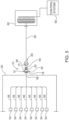
- Fig. 5 a wiring arrangement in accordance with an aspect of the invention is shown.
- the mounting surface 18 of the mounting flange 12 is attached to a machinery housing 52 of a turbomachine.
- the sealing element 20 is located between the mounting surface 18 and the machinery housing 52 thus sealing the mounting flange 12 from the machinery housing 52.
- a plurality of electronic devices 54, such as sensors, may be located within the machinery housing 52.
- Each device 54 includes a lead 56 that is routed from within the machinery housing 52 to a housing opening 58 that forms an exit point on the turbomachine for the leads 56.
- each lead 56 is then attached to a respective terminal end 42 of the receptacle connector 10, as previously described, to terminate the lead 56.
- the turbomachine is a compressor and the sensors are resistance temperature detectors (RTDs) used to monitor various operating parameters of associated compressor bearings used in the compressor.
- the wiring arrangement includes a cable 58 that extends from a junction box 60 electrically connected to a known control system 62 for the turbomachine.
- the female connector 26 is attached to an end of the cable 58. Referring to Fig. 6 , an end view of the female connector 26 is shown.
- the female connector 26 includes female pins 64 that receive the male pins 40 and an internal thread 66 that engages the external thread 22 of the receptacle connector 10. Upon engagement of the internal 66 and external 22 threads, the male 40 and female 64 pins are mated to form an electrical circuit between the control system 62 and the devices 54.
- the present invention conserves space by a factor of three and requires fewer parts than a conventional connector.
- the pins of conventional connectors are either crimped or soldered and thus are substantially permanently affixed to the pins of the connector. If maintenance is needed for the connector, or if one or more leads have to be replaced, the associated pins have to be cut out and the connector has to be rebuilt.
- the conductors 38 of the present invention enable the replacement of leads without having to cut pins and rebuilding the receptacle connector 10.
- the conductors 38 of the invention are integrated into the conductor carrier 28 and thus do not require sealing as with conventional connector pins.
- the present invention also enables pin sizes that are much larger than that provided by conventional connector designs which results in a connector that is substantially more robust than conventional connectors.
- the present invention results in lower material and overhead costs and substantially reduces maintenance and time needed to wire and route machinery instrumentation. Standardized instrument connection details and procedures may also be maintained to support plug and play technologies.
Description
- Aspects of the invention relate to an electrical connector, and more particularly, to an electrical connector having at least one conductor that includes a pin end and a terminal end, wherein the terminal end includes a lead opening that receives a lead and a fastener hole oriented substantially transverse to the lead opening wherein the at least one conductor is held in a conductor carrier having a base portion and at least one extended portion that extends from the base portion to form a staggered arrangement wherein the base and extended portions each include a plurality of channels wherein each channel includes a conductor.
- Rotating and reciprocating turbomachinery typically include electronic instrumentation that monitors machine safety and performance. The instrumentation is typically mounted on and/or inside the machine and requires connections and/or terminations that are routed to an overall machine monitoring system. Installation and routing of the connections and/or terminations is complicated and difficult due to the limited amount of space available inside the machine. Further, the apparatus used for mounting the instrumentation may hinder general maintenance and service to the machinery. It is desirable to provide additional space access to the machines and minimize the labor and effort needed to install and maintain machinery.
-
DE 10 2016 104 082 B3 -
CN 203826578 U describes a connector with high density screw crimping. More than two wiring holes are arranged in a connector body. The wiring holes on the connector are arranged in pairs, and each pair of wiring holes are in up and down split-level arrangement. Pins with the same number of the wiring holes are inserted into the corresponding wiring holes. The head parts of the pins are provided with wiring grooves. The opening directions of the wiring grooves and the wiring holes are consistent. A pressing screw passes through the corresponding wire hole and pin side wall to extend into a wiring groove so as to press a conducting wire or bare wire inserted from the wiring hole. -
US 5 197 903 A describes a bulkhead connector including an array of bus bars extending from a first face to a second face for interconnecting associated power cables on opposing sides of the bulkhead. Embedded within the connector is a substrate of fire-resistant material extending transversely completely across the bulkhead opening, with apertures through which extend the bus bars. Exposed contact sections of the bus bars permit terminals to be fastened thereto, and the connector is adapted to prevent rotation of the fastened terminals during in-service use. - An electrical connector is disclosed for making electrical contact with at least one lead of an electronic device. The connector includes a mounting flange portion and a connector housing portion that extends along a center axis from the mounting flange portion; a connector hole extends through the connector housing and mounting flange portions. The connector also includes at least one conductor having a pin end and a terminal end, wherein the terminal end includes a lead opening that receives the lead and a fastener hole oriented substantially transverse to the lead opening. In addition, the connector includes a fastening element that engages the fastener hole and contacts the lead to form electrical contact between the conductor and the lead. Further, the connector includes a conductor carrier that extends through the connector hole, the conductor carrier is held within the connector housing and mounting flange by an interference fit. The conductor carrier having a base portion and at least one extended portion that extends from the base portion to form a staggered arrangement. In particular, the base and extended portions each include a plurality of channels wherein each channel includes a conductor.
- In addition, a method of attaching a lead from an electronic device to a connector disclosed. The method includes providing a connector housing portion that extends along a center axis. The method also includes providing at least one conductor having a pin end and a terminal end, wherein the terminal end includes a lead opening that receives the lead and a fastener hole oriented substantially transverse to the lead opening. The lead is inserted into the lead opening and the fastening element is engaged with the fastener hole and contacts the lead to form electrical contact between the conductor and the lead. In addition, the method includes providing a conductor carrier that extends through the connector housing, the conductor carrier having a base portion and at least one extended portion that extends from the base portion to form a staggered arrangement. Further, the base and extended portions each include a plurality of channels wherein each channel includes a conductor.
- Those skilled in the art may apply the respective features of the present invention jointly or severally in any combination or sub-combination.
- The exemplary embodiments of the invention are further described in the following detailed description in conjunction with the accompanying drawings, in which:
-
Fig. 1A is a side view of a receptacle electrical connector in accordance with an aspect of the present invention. -
Figs. 1B is a rear view of the receptacle connector alongview lines 1B-1B ofFig. 1A . -
Fig. 1C is a front view of the receptacle connector alongview line 1C-1C ofFig. 1A . -
Fig. 2 is a rear perspective view of the receptacle connector. -
Fig. 3 is a front perspective view of the receptacle connector. -
Fig. 4 is a side view of an electrical conductor in accordance with an aspect of the present invention. -
Fig. 5 depicts a wiring arrangement in accordance with an aspect of the invention. -
Fig. 6 is an end view of a female connector. - To facilitate understanding, identical reference numerals have been used, where possible, to designate identical elements that are common to the figures. The figures are not drawn to scale.
- Although various embodiments that incorporate the teachings of the present disclosure have been shown and described in detail herein, those skilled in the art can readily devise many other varied embodiments that still incorporate these teachings. The scope of the disclosure is not limited in its application to the exemplary embodiment details of construction and the arrangement of components set forth in the description or illustrated in the drawings. The disclosure encompasses other embodiments and of being practiced or of being carried out in various ways. Also, it is to be understood that the phraseology and terminology used herein is for the purpose of description and should not be regarded as limiting. The use of "including," "comprising," or "having" and variations thereof herein is meant to encompass the items listed thereafter and equivalents thereof as well as additional items. Unless specified or limited otherwise, the terms "mounted," "connected," "supported," and "coupled" and variations thereof are used broadly and encompass direct and indirect mountings, connections, supports, and couplings. Further, "connected" and "coupled" are not restricted to physical or mechanical connections or couplings.
- Referring to
Fig. 1A , a side view of a receptacleelectrical connector 10 in accordance with an aspect of the present invention are shown.Figs. 1B and 1C are rear and front views of thereceptacle connector 10 alongview lines 1B-1B and 1C-1C, respectively, ofFig. 1A . Thereceptacle connector 10 includes a mountingflange portion 12 and aconnector housing portion 14 that extends along acenter axis 16 from the mountingflange portion 12. Theconnector housing 14 is substantially round in shape and a size of the mountingflange 12 in a direction orthogonal to thecenter axis 16 is larger than a diameter of theconnector housing 14. In addition, the mountingflange 12 includes a mountingsurface 18 having a sealingelement 20 such as an O-ring (seeFigs. 1B and2 ). Theconnector housing 14 also includesexternal threads 22 which threadably engage with internal threads 24 of a mating cordset female connector 26 (seeFig. 6 ) as will be described. -
Figs. 2 and 3 are rear and front perspective views, respectively, of thereceptacle connector 10. Referring toFigs. 1A-1C ,2 and 3 , thereceptacle connector 10 also includes a contact orconductor carrier 28 that extends through aconnector hole 30 formed in theconnector housing 14 and mountingflange 12. Thecarrier 28 includes abase portion 32 that includes a plurality ofchannels 36. In another embodiment of thecarrier 28, at least oneextended portion 34 extends from thebase portion 32 to form a staggered arrangement for thecarrier 28. Thebase 32 and extended 34 portions each include a plurality ofchannels 36. In an embodiment, eachchannel 36 includes an opening to form a substantiallyU-shaped channel 36. Eachchannel 36 receives aconductor 38 to provide areceptacle connector 10 having a plurality of pins 40 (seeFigs. 3 and1C ) and a corresponding plurality of terminal ends 42 (seeFigs. 1B and2 ). Eachpin 40 is adapted to be inserted into thefemale connector 26. -
Fig. 4 is a side view of theelectrical conductor 38. Theconductor 38 includes a male pin end orpin 40 and aterminal end 42. Thepin 40 andterminal end 42 may be unistructurally or integrally formed as one piece. Eachterminal end 42 includes a lead opening 44 (seeFigs. 1B and2 ) oriented substantially parallel to thecenter axis 16 and afastener hole 46 oriented transverse to the orientation of thelead opening 44. In an embodiment, thefastener hole 46 is threaded. Thecarrier 28 may be fabricated from a thermoplastic material. In an embodiment, eachconductor 38 is integrally molded within itsrespective channel 36 to hold theconductor 38 within thecarrier 28. An adhesive such as an epoxy may be also be used to attach theconductor 38 to thecarrier 28. Thecarrier 28 andconnector hole 30 are both sized such that an interference fit is formed between thecarrier 28 and theconnector hole 30 to thus attach thecarrier 28 to thereceptacle connector 10. An adhesive such as an epoxy may also be used to attach thecarrier 28 to thereceptacle connector 10. - The
lead opening 44 is configured to receive a wire or lead 48 that extends from an electronic device. Upon insertion of thelead 48 into thelead opening 44, afastener element 50, such as a threaded fastener, is engaged with thefastener hole 46 until it contacts thelead 48. Thefastener element 50 then pushes against thelead 48 such that thelead 48 in turn contacts an interior wall of theterminal end 42 to form electrical contact with theconductor 38. In an embodiment, thebase portion 32 includes eightconductors 38 and theextended portion 34 includes fourconductors 38 to enable the attachment of twelve leads 48 to thecarrier 28. Alternatively, thecarrier 28 includes asingle channel 36 that receives aconductor 38. - The
receptacle connector 10 may be used as an electrical termination device that enables electronic instrumentation or devices used in connection with rotating and reciprocating turbomachinery to be readily connected or disconnected locally. Referring toFig. 5 , a wiring arrangement in accordance with an aspect of the invention is shown. The mountingsurface 18 of the mountingflange 12 is attached to amachinery housing 52 of a turbomachine. The sealingelement 20 is located between the mountingsurface 18 and themachinery housing 52 thus sealing the mountingflange 12 from themachinery housing 52. A plurality ofelectronic devices 54, such as sensors, may be located within themachinery housing 52. Eachdevice 54 includes a lead 56 that is routed from within themachinery housing 52 to ahousing opening 58 that forms an exit point on the turbomachine for the leads 56. Eachlead 56 is then attached to a respectiveterminal end 42 of thereceptacle connector 10, as previously described, to terminate thelead 56. In an embodiment, the turbomachine is a compressor and the sensors are resistance temperature detectors (RTDs) used to monitor various operating parameters of associated compressor bearings used in the compressor. The wiring arrangement includes acable 58 that extends from ajunction box 60 electrically connected to a knowncontrol system 62 for the turbomachine. Thefemale connector 26 is attached to an end of thecable 58. Referring toFig. 6 , an end view of thefemale connector 26 is shown. Thefemale connector 26 includesfemale pins 64 that receive the male pins 40 and aninternal thread 66 that engages theexternal thread 22 of thereceptacle connector 10. Upon engagement of the internal 66 and external 22 threads, the male 40 and female 64 pins are mated to form an electrical circuit between thecontrol system 62 and thedevices 54. - It has been found by the inventor herein that the present invention conserves space by a factor of three and requires fewer parts than a conventional connector. Further, the pins of conventional connectors are either crimped or soldered and thus are substantially permanently affixed to the pins of the connector. If maintenance is needed for the connector, or if one or more leads have to be replaced, the associated pins have to be cut out and the connector has to be rebuilt. The
conductors 38 of the present invention enable the replacement of leads without having to cut pins and rebuilding thereceptacle connector 10. - The
conductors 38 of the invention are integrated into theconductor carrier 28 and thus do not require sealing as with conventional connector pins. The present invention also enables pin sizes that are much larger than that provided by conventional connector designs which results in a connector that is substantially more robust than conventional connectors. In addition, the present invention results in lower material and overhead costs and substantially reduces maintenance and time needed to wire and route machinery instrumentation. Standardized instrument connection details and procedures may also be maintained to support plug and play technologies.
Claims (12)
- An electrical connector (10) for making electrical contact with at least one lead (48) of an electronic device (54), comprising:a mounting flange portion (12);a connector housing portion (14) that extends along a center axis (16) from the mounting flange portion (12), wherein a connector hole (30) extends through the connector housing (14) and mounting flange (12) portions;at least one conductor (38) having a pin end (40) and a terminal end (42), wherein the terminal end (42) includes a lead opening (44) that receives the lead (48) and a fastener hole (46) oriented substantially transverse to the lead opening (44) and wherein a fastening element (50) engages the fastener hole (46) and contacts the lead (48) to form electrical contact between the conductor (38) and the lead (48); anda conductor carrier (28) extending through the connector hole (30), wherein the conductor carrier (28) is held within the connector housing (14) and mounting flange (12) by an interference fit and wherein the conductor carrier (28) includes a base portion (32) and at least one extended portion (34) that extends from the base portion (32) to form a staggered arrangement wherein the base (32) and extended (34) portions each include a plurality of channels (36) and wherein each channel (36) includes a conductor (38).
- The connector (10) according to claim 1, wherein the pin (40) and terminal (42) ends of the conductor (38) are unistructurally formed.
- The connector (10) according to claim 1, wherein each channel (36) is substantially U-shaped.
- The connector (10) according to claim 1, wherein each conductor (38) is integrally molded within the channel (36).
- The connector (10) according to claim 1, wherein the lead opening (44) is oriented substantially parallel to the center axis (16).
- The connector (10) according to claim 1, wherein the mounting flange (12) includes a sealing element (20).
- A method of attaching a lead (48) from an electronic device (54) to a connector (10), comprising:providing a connector housing portion (14) that extends along a center axis (16) from a mounting flange portion (12), wherein a connector hole (30) extends through the connector housing (14) and mounting flange (12) portions;providing at least one conductor (38) having a pin end (40) and a terminal end (42), wherein the terminal end (42) includes a lead opening (44) that receives the lead (48) and a fastener hole (46) oriented substantially transverse to the lead opening (44);inserting the lead (48) into the lead opening (44);inserting a fastening element (50) that engages the fastener hole (46) and contacts the lead (48) to form electrical contact between the conductor (38) and the lead (48); andproviding a conductor carrier (28) that extends through the connector hole (30), wherein the conductor carrier (28) is held within the connector housing (14) and mounting flange (12) by an interference fit, the conductor carrier (28) having a base portion (32) and at least one extended portion (34) that extends from the base portion (32) to form a staggered arrangement wherein the base (32) and extended (34) portions each include a plurality of channels (36) and wherein each channel (36) includes a conductor (38).
- The method according to claim 7, wherein the pin (40) and terminal (42) ends of the conductor (38) are unistructurally formed.
- The method according to claim 7, wherein each channel (36) is substantially U-shaped.
- The method according to claim 7, wherein each conductor (38) is integrally molded within the channel (36).
- The method according to claim 7, wherein the conductor carrier (28) is held within the connector housing (14) by an interference fit.
- The method according to claim 7, wherein the lead opening (44) is oriented substantially parallel to the center axis (16).
Applications Claiming Priority (1)
| Application Number | Priority Date | Filing Date | Title |
|---|---|---|---|
| PCT/US2018/033239 WO2019221740A1 (en) | 2018-05-17 | 2018-05-17 | Electrical connector having a staggered contact carrier |
Publications (2)
| Publication Number | Publication Date |
|---|---|
| EP3782232A1 EP3782232A1 (en) | 2021-02-24 |
| EP3782232B1 true EP3782232B1 (en) | 2023-02-15 |
Family
ID=62567825
Family Applications (1)
| Application Number | Title | Priority Date | Filing Date |
|---|---|---|---|
| EP18730568.5A Active EP3782232B1 (en) | 2018-05-17 | 2018-05-17 | Electrical connector having a staggered contact carrier |
Country Status (4)
| Country | Link |
|---|---|
| US (1) | US11404803B2 (en) |
| EP (1) | EP3782232B1 (en) |
| CN (1) | CN112074994B (en) |
| WO (1) | WO2019221740A1 (en) |
Family Cites Families (18)
| Publication number | Priority date | Publication date | Assignee | Title |
|---|---|---|---|---|
| US5197903A (en) * | 1992-03-02 | 1993-03-30 | Amp Incorporated | Firewall connector |
| DE10246450A1 (en) * | 2002-10-04 | 2004-04-29 | Wieland Electric Gmbh | Electrical connector |
| US20050112953A1 (en) * | 2003-11-25 | 2005-05-26 | Ratchford Lloyd G. | Slotted contact retention and alignment device for contact assembles |
| FR2868884B1 (en) * | 2004-04-07 | 2012-11-30 | Radiall Sa | CABLE CONNECTOR COMPRISING A PLURALITY OF TORSADED CONDUCTORS |
| DE202007005073U1 (en) * | 2007-04-05 | 2007-06-28 | Coninvers Elektrotechnische Bauelemente Gmbh | Electrical plug connector has guard ring that can be pushed onto contact support and that has at least one sprung snap element for reversible locking to plug housing |
| DE202009000542U1 (en) * | 2009-01-14 | 2010-06-02 | Coninvers Gmbh | Electrical plug-in connector with snap-in isolating body that can be released without tools |
| DE102009021594B4 (en) * | 2009-04-09 | 2018-04-12 | Phoenix Contact Gmbh & Co. Kg | Electrical connector and electrical connector and method for connecting the remainder of a multicore cable to an electrical connector |
| US7901238B1 (en) | 2009-08-13 | 2011-03-08 | Tyco Electronics Corporation | Terminal block and board assembly for an electrical connector |
| DK2736124T3 (en) * | 2012-11-26 | 2016-04-18 | Phoenix Contact Connector Technology Gmbh | Electrical connector with latched insulating body som kan detached with a tool and release tool |
| CN203826578U (en) * | 2014-04-09 | 2014-09-10 | 厦门西霸士连接器有限公司 | Connector with high density screw crimping |
| CN204067664U (en) * | 2014-08-12 | 2014-12-31 | 泰科电子(上海)有限公司 | Electric connector |
| CN104332756B (en) * | 2014-11-25 | 2016-04-20 | 泰州市航宇电器有限公司 | Just the connector construction dismantled between a kind of pedestal and housing |
| US9270052B1 (en) * | 2015-03-31 | 2016-02-23 | Tyco Electronics Corporation | Pass-through connector system |
| CN104882751A (en) * | 2015-06-02 | 2015-09-02 | 杨晓锋 | High-stability radio-frequency coaxial connector |
| DE102015210336A1 (en) * | 2015-06-03 | 2016-12-08 | Te Connectivity Germany Gmbh | Holding block and modular plug insert |
| DE102016104082B3 (en) * | 2016-03-07 | 2017-02-09 | Walther-Werke Ferdinand Walther Gmbh | Electrical plug-in device with a latching mechanism |
| WO2017197134A1 (en) * | 2016-05-11 | 2017-11-16 | Hubbell Incorporated | Power connector with integrated power monitoring |
| JP6571700B2 (en) * | 2017-02-01 | 2019-09-04 | 矢崎総業株式会社 | connector |
-
2018
- 2018-05-17 EP EP18730568.5A patent/EP3782232B1/en active Active
- 2018-05-17 US US17/051,465 patent/US11404803B2/en active Active
- 2018-05-17 CN CN201880093164.XA patent/CN112074994B/en active Active
- 2018-05-17 WO PCT/US2018/033239 patent/WO2019221740A1/en unknown
Also Published As
| Publication number | Publication date |
|---|---|
| US11404803B2 (en) | 2022-08-02 |
| WO2019221740A1 (en) | 2019-11-21 |
| EP3782232A1 (en) | 2021-02-24 |
| CN112074994A (en) | 2020-12-11 |
| US20210242613A1 (en) | 2021-08-05 |
| CN112074994B (en) | 2022-07-29 |
Similar Documents
| Publication | Publication Date | Title |
|---|---|---|
| US7413478B2 (en) | Electric contact for contacting a protecting conductor with conductive housing | |
| US20170110824A1 (en) | Plug | |
| CN212725816U (en) | Multiphase connector for electric power system | |
| CN107925183A (en) | Plug-in connector | |
| KR20100137444A (en) | Electrical termination device | |
| KR20150004905A (en) | Insulating body of plug connector | |
| US9306296B2 (en) | Contacting device of an electric plug-in connector | |
| EP0431206B1 (en) | Grounding shield connector and method | |
| KR20180082323A (en) | Device for receiving and supporting bus bars | |
| US6960100B2 (en) | Grounding apparatus for an electronic module | |
| US3675185A (en) | Electrical connectors for distribution plate and rack and panel applications | |
| US20050207097A1 (en) | Neutral-ground connector subassembly | |
| US6086388A (en) | Auxiliary switch system for use with removable circuit breaker | |
| EP3782232B1 (en) | Electrical connector having a staggered contact carrier | |
| US11201437B2 (en) | Insulating connector for an electrical cable | |
| US9653858B2 (en) | Wall feed-through device | |
| US10971849B2 (en) | Connector and connector assembly | |
| JPS6122532B2 (en) | ||
| US5071366A (en) | Circular IDC connector | |
| EP1369956A1 (en) | Box for branching off conductors of a cable | |
| EP0105589A1 (en) | Gender change connector | |
| CN211265781U (en) | Binding post protection device and be used for bellows subassembly of threading | |
| CN217087067U (en) | Connector switching device and connector assembly | |
| US20240072487A1 (en) | Flexible boot for deutsch connector | |
| KR200485894Y1 (en) | A conmined structure of a multi-contact connector |
Legal Events
| Date | Code | Title | Description |
|---|---|---|---|
| STAA | Information on the status of an ep patent application or granted ep patent |
Free format text: STATUS: UNKNOWN |
|
| STAA | Information on the status of an ep patent application or granted ep patent |
Free format text: STATUS: THE INTERNATIONAL PUBLICATION HAS BEEN MADE |
|
| PUAI | Public reference made under article 153(3) epc to a published international application that has entered the european phase |
Free format text: ORIGINAL CODE: 0009012 |
|
| STAA | Information on the status of an ep patent application or granted ep patent |
Free format text: STATUS: REQUEST FOR EXAMINATION WAS MADE |
|
| 17P | Request for examination filed |
Effective date: 20201116 |
|
| AK | Designated contracting states |
Kind code of ref document: A1 Designated state(s): AL AT BE BG CH CY CZ DE DK EE ES FI FR GB GR HR HU IE IS IT LI LT LU LV MC MK MT NL NO PL PT RO RS SE SI SK SM TR |
|
| AX | Request for extension of the european patent |
Extension state: BA ME |
|
| DAV | Request for validation of the european patent (deleted) | ||
| DAX | Request for extension of the european patent (deleted) | ||
| GRAP | Despatch of communication of intention to grant a patent |
Free format text: ORIGINAL CODE: EPIDOSNIGR1 |
|
| STAA | Information on the status of an ep patent application or granted ep patent |
Free format text: STATUS: GRANT OF PATENT IS INTENDED |
|
| INTG | Intention to grant announced |
Effective date: 20220927 |
|
| GRAS | Grant fee paid |
Free format text: ORIGINAL CODE: EPIDOSNIGR3 |
|
| GRAA | (expected) grant |
Free format text: ORIGINAL CODE: 0009210 |
|
| STAA | Information on the status of an ep patent application or granted ep patent |
Free format text: STATUS: THE PATENT HAS BEEN GRANTED |
|
| AK | Designated contracting states |
Kind code of ref document: B1 Designated state(s): AL AT BE BG CH CY CZ DE DK EE ES FI FR GB GR HR HU IE IS IT LI LT LU LV MC MK MT NL NO PL PT RO RS SE SI SK SM TR |
|
| REG | Reference to a national code |
Ref country code: CH Ref legal event code: EP Ref country code: GB Ref legal event code: FG4D |
|
| REG | Reference to a national code |
Ref country code: DE Ref legal event code: R096 Ref document number: 602018046147 Country of ref document: DE |
|
| REG | Reference to a national code |
Ref country code: AT Ref legal event code: REF Ref document number: 1548731 Country of ref document: AT Kind code of ref document: T Effective date: 20230315 Ref country code: IE Ref legal event code: FG4D |
|
| REG | Reference to a national code |
Ref country code: LT Ref legal event code: MG9D |
|
| REG | Reference to a national code |
Ref country code: NL Ref legal event code: MP Effective date: 20230215 |
|
| REG | Reference to a national code |
Ref country code: AT Ref legal event code: MK05 Ref document number: 1548731 Country of ref document: AT Kind code of ref document: T Effective date: 20230215 |
|
| PG25 | Lapsed in a contracting state [announced via postgrant information from national office to epo] |
Ref country code: RS Free format text: LAPSE BECAUSE OF FAILURE TO SUBMIT A TRANSLATION OF THE DESCRIPTION OR TO PAY THE FEE WITHIN THE PRESCRIBED TIME-LIMIT Effective date: 20230215 Ref country code: PT Free format text: LAPSE BECAUSE OF FAILURE TO SUBMIT A TRANSLATION OF THE DESCRIPTION OR TO PAY THE FEE WITHIN THE PRESCRIBED TIME-LIMIT Effective date: 20230615 Ref country code: NO Free format text: LAPSE BECAUSE OF FAILURE TO SUBMIT A TRANSLATION OF THE DESCRIPTION OR TO PAY THE FEE WITHIN THE PRESCRIBED TIME-LIMIT Effective date: 20230515 Ref country code: NL Free format text: LAPSE BECAUSE OF FAILURE TO SUBMIT A TRANSLATION OF THE DESCRIPTION OR TO PAY THE FEE WITHIN THE PRESCRIBED TIME-LIMIT Effective date: 20230215 Ref country code: LV Free format text: LAPSE BECAUSE OF FAILURE TO SUBMIT A TRANSLATION OF THE DESCRIPTION OR TO PAY THE FEE WITHIN THE PRESCRIBED TIME-LIMIT Effective date: 20230215 Ref country code: LT Free format text: LAPSE BECAUSE OF FAILURE TO SUBMIT A TRANSLATION OF THE DESCRIPTION OR TO PAY THE FEE WITHIN THE PRESCRIBED TIME-LIMIT Effective date: 20230215 Ref country code: HR Free format text: LAPSE BECAUSE OF FAILURE TO SUBMIT A TRANSLATION OF THE DESCRIPTION OR TO PAY THE FEE WITHIN THE PRESCRIBED TIME-LIMIT Effective date: 20230215 Ref country code: ES Free format text: LAPSE BECAUSE OF FAILURE TO SUBMIT A TRANSLATION OF THE DESCRIPTION OR TO PAY THE FEE WITHIN THE PRESCRIBED TIME-LIMIT Effective date: 20230215 Ref country code: AT Free format text: LAPSE BECAUSE OF FAILURE TO SUBMIT A TRANSLATION OF THE DESCRIPTION OR TO PAY THE FEE WITHIN THE PRESCRIBED TIME-LIMIT Effective date: 20230215 |
|
| PGFP | Annual fee paid to national office [announced via postgrant information from national office to epo] |
Ref country code: IT Payment date: 20230525 Year of fee payment: 6 Ref country code: FR Payment date: 20230523 Year of fee payment: 6 Ref country code: DE Payment date: 20230530 Year of fee payment: 6 Ref country code: CH Payment date: 20230602 Year of fee payment: 6 |
|
| PG25 | Lapsed in a contracting state [announced via postgrant information from national office to epo] |
Ref country code: SE Free format text: LAPSE BECAUSE OF FAILURE TO SUBMIT A TRANSLATION OF THE DESCRIPTION OR TO PAY THE FEE WITHIN THE PRESCRIBED TIME-LIMIT Effective date: 20230215 Ref country code: PL Free format text: LAPSE BECAUSE OF FAILURE TO SUBMIT A TRANSLATION OF THE DESCRIPTION OR TO PAY THE FEE WITHIN THE PRESCRIBED TIME-LIMIT Effective date: 20230215 Ref country code: IS Free format text: LAPSE BECAUSE OF FAILURE TO SUBMIT A TRANSLATION OF THE DESCRIPTION OR TO PAY THE FEE WITHIN THE PRESCRIBED TIME-LIMIT Effective date: 20230615 Ref country code: GR Free format text: LAPSE BECAUSE OF FAILURE TO SUBMIT A TRANSLATION OF THE DESCRIPTION OR TO PAY THE FEE WITHIN THE PRESCRIBED TIME-LIMIT Effective date: 20230516 Ref country code: FI Free format text: LAPSE BECAUSE OF FAILURE TO SUBMIT A TRANSLATION OF THE DESCRIPTION OR TO PAY THE FEE WITHIN THE PRESCRIBED TIME-LIMIT Effective date: 20230215 |
|
| RAP2 | Party data changed (patent owner data changed or rights of a patent transferred) |
Owner name: SIEMENS ENERGY, INC. |
|
| PG25 | Lapsed in a contracting state [announced via postgrant information from national office to epo] |
Ref country code: SM Free format text: LAPSE BECAUSE OF FAILURE TO SUBMIT A TRANSLATION OF THE DESCRIPTION OR TO PAY THE FEE WITHIN THE PRESCRIBED TIME-LIMIT Effective date: 20230215 Ref country code: RO Free format text: LAPSE BECAUSE OF FAILURE TO SUBMIT A TRANSLATION OF THE DESCRIPTION OR TO PAY THE FEE WITHIN THE PRESCRIBED TIME-LIMIT Effective date: 20230215 Ref country code: EE Free format text: LAPSE BECAUSE OF FAILURE TO SUBMIT A TRANSLATION OF THE DESCRIPTION OR TO PAY THE FEE WITHIN THE PRESCRIBED TIME-LIMIT Effective date: 20230215 Ref country code: DK Free format text: LAPSE BECAUSE OF FAILURE TO SUBMIT A TRANSLATION OF THE DESCRIPTION OR TO PAY THE FEE WITHIN THE PRESCRIBED TIME-LIMIT Effective date: 20230215 Ref country code: CZ Free format text: LAPSE BECAUSE OF FAILURE TO SUBMIT A TRANSLATION OF THE DESCRIPTION OR TO PAY THE FEE WITHIN THE PRESCRIBED TIME-LIMIT Effective date: 20230215 |
|
| REG | Reference to a national code |
Ref country code: DE Ref legal event code: R097 Ref document number: 602018046147 Country of ref document: DE |
|
| PG25 | Lapsed in a contracting state [announced via postgrant information from national office to epo] |
Ref country code: SK Free format text: LAPSE BECAUSE OF FAILURE TO SUBMIT A TRANSLATION OF THE DESCRIPTION OR TO PAY THE FEE WITHIN THE PRESCRIBED TIME-LIMIT Effective date: 20230215 |
|
| REG | Reference to a national code |
Ref country code: DE Ref legal event code: R081 Ref document number: 602018046147 Country of ref document: DE Owner name: SIEMENS ENERGY, INC., ORLANDO, US Free format text: FORMER OWNER: DRESSER RAND COMPANY, HOUSTON, TX, US |
|
| PLBE | No opposition filed within time limit |
Free format text: ORIGINAL CODE: 0009261 |
|
| STAA | Information on the status of an ep patent application or granted ep patent |
Free format text: STATUS: NO OPPOSITION FILED WITHIN TIME LIMIT |
|
| PG25 | Lapsed in a contracting state [announced via postgrant information from national office to epo] |
Ref country code: MC Free format text: LAPSE BECAUSE OF FAILURE TO SUBMIT A TRANSLATION OF THE DESCRIPTION OR TO PAY THE FEE WITHIN THE PRESCRIBED TIME-LIMIT Effective date: 20230215 |
|
| 26N | No opposition filed |
Effective date: 20231116 |
|
| GBPC | Gb: european patent ceased through non-payment of renewal fee |
Effective date: 20230517 |
|
| REG | Reference to a national code |
Ref country code: BE Ref legal event code: MM Effective date: 20230531 |
|
| PG25 | Lapsed in a contracting state [announced via postgrant information from national office to epo] |
Ref country code: SI Free format text: LAPSE BECAUSE OF FAILURE TO SUBMIT A TRANSLATION OF THE DESCRIPTION OR TO PAY THE FEE WITHIN THE PRESCRIBED TIME-LIMIT Effective date: 20230215 Ref country code: MC Free format text: LAPSE BECAUSE OF FAILURE TO SUBMIT A TRANSLATION OF THE DESCRIPTION OR TO PAY THE FEE WITHIN THE PRESCRIBED TIME-LIMIT Effective date: 20230215 Ref country code: LU Free format text: LAPSE BECAUSE OF NON-PAYMENT OF DUE FEES Effective date: 20230517 |
|
| REG | Reference to a national code |
Ref country code: IE Ref legal event code: MM4A |
|
| PG25 | Lapsed in a contracting state [announced via postgrant information from national office to epo] |
Ref country code: IE Free format text: LAPSE BECAUSE OF NON-PAYMENT OF DUE FEES Effective date: 20230517 |